EP4249987A1 - Reflective pupil relay optics for mems scanning system - Google Patents
Reflective pupil relay optics for mems scanning system Download PDFInfo
- Publication number
- EP4249987A1 EP4249987A1 EP23160863.9A EP23160863A EP4249987A1 EP 4249987 A1 EP4249987 A1 EP 4249987A1 EP 23160863 A EP23160863 A EP 23160863A EP 4249987 A1 EP4249987 A1 EP 4249987A1
- Authority
- EP
- European Patent Office
- Prior art keywords
- laser beam
- rgb laser
- mirror
- axis
- combined rgb
- Prior art date
- Legal status (The legal status is an assumption and is not a legal conclusion. Google has not performed a legal analysis and makes no representation as to the accuracy of the status listed.)
- Withdrawn
Links
Images


Classifications
-
- G—PHYSICS
- G01—MEASURING; TESTING
- G01S—RADIO DIRECTION-FINDING; RADIO NAVIGATION; DETERMINING DISTANCE OR VELOCITY BY USE OF RADIO WAVES; LOCATING OR PRESENCE-DETECTING BY USE OF THE REFLECTION OR RERADIATION OF RADIO WAVES; ANALOGOUS ARRANGEMENTS USING OTHER WAVES
- G01S7/00—Details of systems according to groups G01S13/00, G01S15/00, G01S17/00
- G01S7/48—Details of systems according to groups G01S13/00, G01S15/00, G01S17/00 of systems according to group G01S17/00
- G01S7/481—Constructional features, e.g. arrangements of optical elements
- G01S7/4817—Constructional features, e.g. arrangements of optical elements relating to scanning
-
- G—PHYSICS
- G02—OPTICS
- G02B—OPTICAL ELEMENTS, SYSTEMS OR APPARATUS
- G02B27/00—Optical systems or apparatus not provided for by any of the groups G02B1/00 - G02B26/00, G02B30/00
- G02B27/01—Head-up displays
-
- G—PHYSICS
- G02—OPTICS
- G02B—OPTICAL ELEMENTS, SYSTEMS OR APPARATUS
- G02B17/00—Systems with reflecting surfaces, with or without refracting elements
- G02B17/02—Catoptric systems, e.g. image erecting and reversing system
- G02B17/06—Catoptric systems, e.g. image erecting and reversing system using mirrors only, i.e. having only one curved mirror
- G02B17/0647—Catoptric systems, e.g. image erecting and reversing system using mirrors only, i.e. having only one curved mirror using more than three curved mirrors
- G02B17/0657—Catoptric systems, e.g. image erecting and reversing system using mirrors only, i.e. having only one curved mirror using more than three curved mirrors off-axis or unobscured systems in which all of the mirrors share a common axis of rotational symmetry
-
- G—PHYSICS
- G02—OPTICS
- G02B—OPTICAL ELEMENTS, SYSTEMS OR APPARATUS
- G02B17/00—Systems with reflecting surfaces, with or without refracting elements
- G02B17/02—Catoptric systems, e.g. image erecting and reversing system
- G02B17/023—Catoptric systems, e.g. image erecting and reversing system for extending or folding an optical path, e.g. delay lines
-
- G—PHYSICS
- G02—OPTICS
- G02B—OPTICAL ELEMENTS, SYSTEMS OR APPARATUS
- G02B17/00—Systems with reflecting surfaces, with or without refracting elements
- G02B17/02—Catoptric systems, e.g. image erecting and reversing system
- G02B17/06—Catoptric systems, e.g. image erecting and reversing system using mirrors only, i.e. having only one curved mirror
- G02B17/0647—Catoptric systems, e.g. image erecting and reversing system using mirrors only, i.e. having only one curved mirror using more than three curved mirrors
-
- G—PHYSICS
- G02—OPTICS
- G02B—OPTICAL ELEMENTS, SYSTEMS OR APPARATUS
- G02B26/00—Optical devices or arrangements for the control of light using movable or deformable optical elements
- G02B26/08—Optical devices or arrangements for the control of light using movable or deformable optical elements for controlling the direction of light
- G02B26/0816—Optical devices or arrangements for the control of light using movable or deformable optical elements for controlling the direction of light by means of one or more reflecting elements
- G02B26/0833—Optical devices or arrangements for the control of light using movable or deformable optical elements for controlling the direction of light by means of one or more reflecting elements the reflecting element being a micromechanical device, e.g. a MEMS mirror, DMD
-
- G—PHYSICS
- G02—OPTICS
- G02B—OPTICAL ELEMENTS, SYSTEMS OR APPARATUS
- G02B26/00—Optical devices or arrangements for the control of light using movable or deformable optical elements
- G02B26/08—Optical devices or arrangements for the control of light using movable or deformable optical elements for controlling the direction of light
- G02B26/10—Scanning systems
-
- G—PHYSICS
- G02—OPTICS
- G02B—OPTICAL ELEMENTS, SYSTEMS OR APPARATUS
- G02B26/00—Optical devices or arrangements for the control of light using movable or deformable optical elements
- G02B26/08—Optical devices or arrangements for the control of light using movable or deformable optical elements for controlling the direction of light
- G02B26/10—Scanning systems
- G02B26/101—Scanning systems with both horizontal and vertical deflecting means, e.g. raster or XY scanners
-
- G—PHYSICS
- G02—OPTICS
- G02B—OPTICAL ELEMENTS, SYSTEMS OR APPARATUS
- G02B6/00—Light guides; Structural details of arrangements comprising light guides and other optical elements, e.g. couplings
- G02B6/24—Coupling light guides
- G02B6/42—Coupling light guides with opto-electronic elements
- G02B6/4201—Packages, e.g. shape, construction, internal or external details
- G02B6/4204—Packages, e.g. shape, construction, internal or external details the coupling comprising intermediate optical elements, e.g. lenses, holograms
- G02B6/4215—Packages, e.g. shape, construction, internal or external details the coupling comprising intermediate optical elements, e.g. lenses, holograms the intermediate optical elements being wavelength selective optical elements, e.g. variable wavelength optical modules or wavelength lockers
-
- H—ELECTRICITY
- H04—ELECTRIC COMMUNICATION TECHNIQUE
- H04N—PICTORIAL COMMUNICATION, e.g. TELEVISION
- H04N9/00—Details of colour television systems
- H04N9/12—Picture reproducers
- H04N9/31—Projection devices for colour picture display, e.g. using electronic spatial light modulators [ESLM]
- H04N9/3129—Projection devices for colour picture display, e.g. using electronic spatial light modulators [ESLM] scanning a light beam on the display screen
-
- H—ELECTRICITY
- H04—ELECTRIC COMMUNICATION TECHNIQUE
- H04N—PICTORIAL COMMUNICATION, e.g. TELEVISION
- H04N9/00—Details of colour television systems
- H04N9/12—Picture reproducers
- H04N9/31—Projection devices for colour picture display, e.g. using electronic spatial light modulators [ESLM]
- H04N9/3141—Constructional details thereof
- H04N9/3173—Constructional details thereof wherein the projection device is specially adapted for enhanced portability
-
- G—PHYSICS
- G02—OPTICS
- G02B—OPTICAL ELEMENTS, SYSTEMS OR APPARATUS
- G02B27/00—Optical systems or apparatus not provided for by any of the groups G02B1/00 - G02B26/00, G02B30/00
- G02B27/01—Head-up displays
- G02B27/0101—Head-up displays characterised by optical features
- G02B2027/011—Head-up displays characterised by optical features comprising device for correcting geometrical aberrations, distortion
-
- G—PHYSICS
- G02—OPTICS
- G02B—OPTICAL ELEMENTS, SYSTEMS OR APPARATUS
- G02B27/00—Optical systems or apparatus not provided for by any of the groups G02B1/00 - G02B26/00, G02B30/00
- G02B27/0081—Optical systems or apparatus not provided for by any of the groups G02B1/00 - G02B26/00, G02B30/00 with means for altering, e.g. enlarging, the entrance or exit pupil
-
- G—PHYSICS
- G02—OPTICS
- G02B—OPTICAL ELEMENTS, SYSTEMS OR APPARATUS
- G02B27/00—Optical systems or apparatus not provided for by any of the groups G02B1/00 - G02B26/00, G02B30/00
- G02B27/01—Head-up displays
- G02B27/017—Head mounted
- G02B27/0172—Head mounted characterised by optical features
Definitions
- This disclosure is related to the field of optics for use in laser scanning projectors.
- a laser scanning projector is a small, portable electronic device.
- Laser scanning projectors are typically paired to, or incorporated within, user devices such as smart glasses, smartphones, tablets, laptops, and head mounted devices, and are used to project images onto a projection surface, such as a wall, holographic surface, or inner display surface of virtual or augmented reality glasses.
- Laser scanning projectors are also used in depth sensing cameras and Light Detection and Ranging (LIDAR) systems.
- LIDAR Light Detection and Ranging
- such laser scanning projectors typically include a projection subsystem and an optical module.
- the paired user device serves an image stream (e.g., a video stream) to the projection subsystem.
- the projection subsystem properly drives the optical module to project the image stream onto the projection surface for viewing.
- the projection subsystem properly drives the optical module to project light pulses at a scene that reflect off objects in the scene.
- a time of flight of the emitted laser pulse is determined. Given this time of flight and with the understanding of the direction of emission of the laser pulse, a three-dimensional map of objects in the scene can be formed and utilized.
- Typical optical modules are comprised of a laser source and one or more microelectromechanical system (MEMS) mirrors that scan the laser beam produced by the laser source across the projection surface in a projection pattern.
- MEMS microelectromechanical system
- the projection subsystem controls the driving of the laser source and the driving of the movement of the one or more MEMS mirrors, and by modulating the laser beam according to its position on the projection surface, while the laser beam is scanned in the projection pattern, the image stream is displayed, or the light pulses are suitable directed at the scene.
- Augmented reality systems function by allowing ambient light from a user's surroundings together with directing light displaying additional visual information toward the user's eye.
- a waveguide may be used to accomplish this mixing of ambient light and additional visual information in a way that is visible to the user.
- the waveguide may receive ambient light from the user's surroundings and may have the additional information displayed thereon through the use of a laser scanning projector.
- the field of view of the visual information displayed to the user through the waveguide is related to the pupil size of the light directed onto the waveguide by the laser scanning projector. The larger the pupil size of the light directed onto the waveguide, generally, the more efficient the waveguide and the better the performance provided by the waveguide.
- an aim of the present invention is to devise a solution that has high performances and small dimensions.
- an optical module and an optical system are provided, as defined in the attached claims.
- the optical module includes a RGB laser source configured to generate a combined RGB laser beam, a fast axis mirror arranged along a first path to receive the combined RGB laser beam and being drivable to scan the combined RGB laser beam along a fast axis, three optical surface magnification mirrors receiving the combined RGB laser beam as it is scanned along the fast axis and magnifying a diameter of the combined RGB laser beam, a slow axis mirror receiving the combined RGB laser beam after magnification and being drivable to scan the combined RGB laser beam along a slow axis, and an Offner mirror relay receiving the combined RGB laser beam as it is scanned along the slow axis and reflecting the combined RGB laser beam along a second path toward an exit aperture of the optical module.
- a RGB laser source configured to generate a combined RGB laser beam
- a fast axis mirror arranged along a first path to receive the combined RGB laser beam and being drivable to scan the combined RGB laser beam along a fast axis
- three optical surface magnification mirrors receiving the combined RGB
- the diffractive waveguide has an input diffractive grating defined therein and is positioned such that the combined RGB laser beam passes from the exit aperture of the optical module into the input diffractive grating, the diffractive waveguide having an output diffractive grating to be positioned adjacent to a user's eye.
- the control circuitry is configured to modulate the RGB laser source according to input image data so that as the combined RGB laser beam is scanned along the fast axis and slow axis, images represented by the input image data are visible to the user's eye.
- a first folding mirror may be configured to receive the combined RGB laser beam from the RGB laser source and reflecting the combined RGB laser beam along the first path.
- a second folding mirror may be arranged along the second desired path and receive the combined RGB laser beam to reflect the combined RGB laser beam toward the exit aperture of the optical module.
- the three optical surface magnification mirrors may be a first concave mirror receiving the combined RGB laser beam as it is scanned along the fast axis and reflecting the combined RGB laser beam along a first internal path, a first convex mirror arranged along the first internal path to receive the combined RGB laser beam and reflecting the combined RGB laser beam along a second internal path, and a second concave mirror arranged along the second internal path to receive the combined RGB laser beam and reflecting the combined RGB laser beam toward the slow axis mirror.
- the first concave mirror, the first convex mirror, and the second concave mirror may cooperate to magnify the diameter of the combined RGB laser beam.
- the Offner mirror relay may include a spherical concave mirror receiving the combined RGB laser beam as it is scanned along the slow axis and reflecting the combined RGB laser beam along a third internal path, and a spherical convex mirror arranged along the third internal path to receive the combined RGB laser beam and reflecting the combined RGB laser beam along a fourth internal path different than the third internal path back toward the spherical concave mirror.
- the spherical concave mirror may reflect the combined RGB laser beam, as received along the fourth internal path, toward the exit aperture of the optical module.
- the fast axis mirror may be a first microelectromechanical system (MEMS) micromirror configured to be driveable at resonance to scan the combined RGB laser beam along the fast axis.
- MEMS microelectromechanical system
- the slow axis mirror may be a second MEMS micromirror configured to be driveable linearly to scan the combined RGB laser beam along the slow axis.
- an optical module including a fast axis mirror arranged along a first path to receive a combined RGB laser beam and being drivable to scan the combined RGB laser beam along a fast axis, and three optical surface magnification mirrors receiving the combined RGB laser beam as it is scanned along the fast axis.
- the three optical surface magnification mirrors include a first concave mirror receiving the combined RGB laser beam as it is scanned along the fast axis and reflecting the combined RGB laser beam along a first internal path, a first convex mirror arranged along the first internal path to receive the combined RGB laser beam and reflecting the combined RGB laser beam along a second internal path, and a second concave mirror arranged along the second internal path to receive the combined RGB laser beam and reflecting the combined RGB laser beam toward the slow axis mirror.
- the first concave mirror, the first convex mirror, and the second concave mirror cooperate to magnify a diameter of the combined RGB laser beam.
- a slow axis mirror receives the combined RGB laser beam after magnification, the slow axis mirror being drivable to scan the combined RGB laser beam along a slow axis.
- An Offner mirror relay receives the combined RGB laser beam as it is scanned along the slow axis and reflecting the combined RGB laser beam along a second path toward an exit aperture of the optical module.
- the Offner mirror relay may be formed by a spherical concave mirror receiving the combined RGB laser beam as it is scanned along the slow axis and reflecting the combined RGB laser beam along a third internal path, and a spherical convex mirror arranged along the third internal path to receive the combined RGB laser beam, the spherical convex mirror reflecting the combined RGB laser beam along a fourth internal path different than the third internal path back toward the spherical concave mirror.
- the spherical concave mirror may reflect the combined RGB laser beam, as received along the fourth internal path, toward the exit aperture of the optical module.
- a RGB laser source may be configured to generate the combined RGB laser beam.
- a first folding mirror may be configured to receive the combined RGB laser beam from the RGB laser source and reflect the combined RGB laser beam along the first path.
- a second folding mirror may be arranged along the second desired path and receive the combined RGB laser beam to reflect the combined RGB laser beam toward the exit aperture of the optical module.
- the fast axis mirror may be a first microelectromechanical systems (MEMS) micromirror configured to be driveable at resonance to scan the combined RGB laser beam along the fast axis
- the slow axis mirror may be a second MEMS micromirror configured to be driveable linearly to scan the combined RGB laser beam along the slow axis.
- MEMS microelectromechanical systems
- an optical module including a RGB laser source configured to generate a combined RGB laser beam, a first folding mirror configured to receive the combined RGB laser beam from the RGB laser source and reflecting the combined RGB laser beam along the first path, a fast axis microelectromechanical systems (MEMS) mirror arranged along the first path to receive the combined RGB laser beam and being drivable to scan the combined RGB laser beam along a fast axis, three optical surface magnification mirrors receiving the combined RGB laser beam as it is scanned along the fast axis and magnifying a diameter of the combined RGB laser beam, a slow axis MEMS mirror receiving the combined RGB laser beam after magnification and being drivable to scan the combined RGB laser beam along a slow axis, an Offner mirror relay receiving the combined RGB laser beam as it is scanned along the slow axis and reflecting the combined RGB laser beam along a second path toward an exit aperture of the optical module, and a second folding mirror arranged along the second desired path and receiving the combined RGB laser beam to reflect the combined RGB laser beam toward
- MEMS
- the three optical surface magnification mirrors may be a first concave mirror receiving the combined RGB laser beam as it is scanned along the fast axis and reflecting the combined RGB laser beam along a first internal path, a first convex mirror arranged along the first internal path to receive the combined RGB laser beam and reflecting the combined RGB laser beam along a second internal path, and a second concave mirror arranged along the second internal path to receive the combined RGB laser beam and reflecting the combined RGB laser beam toward the slow axis mirror.
- the first concave mirror, the first convex mirror, and the second concave mirror may cooperate to magnify a diameter of the combined RGB laser beam;
- the Offner mirror relay may be formed by a spherical concave mirror receiving the combined RGB laser beam as it is scanned along the slow axis and reflecting the combined RGB laser beam along a third internal path, and a spherical convex mirror arranged along the third internal path to receive the combined RGB laser beam, the spherical convex mirror reflecting the combined RGB laser beam along a fourth internal path different than the third internal path back toward the spherical concave mirror.
- the optical module includes a laser source configured to generate a laser beam, a first axis mirror arranged along a first path to receive the laser beam and being drivable to scan the laser beam along a first axis, three optical surface magnification mirrors receiving the laser beam as it is scanned along the first axis and magnifying a diameter of the laser beam, a second axis mirror receiving the laser beam after magnification and being drivable to scan the laser beam along a second axis, and an Offner mirror relay receiving the laser beam as it is scanned along the slow axis and reflecting the laser beam along a second path toward an exit aperture of the optical module.
- the three optical surface magnification mirrors may include a first concave mirror receiving the laser beam as it is scanned along the first axis and reflecting the laser beam along a first internal path, a first convex mirror arranged along the first internal path to receive the laser beam, the first convex mirror reflecting the laser beam along a second internal path, and a second concave mirror arranged along the second internal path to receive the laser beam, the second concave mirror reflecting the laser beam toward the second axis mirror.
- the first concave mirror, the first convex mirror, and the second concave mirror may cooperate to magnify the diameter of the laser beam.
- the Offner mirror relay may be formed by a spherical concave mirror receiving the laser beam as it is scanned along the second axis and reflecting the laser beam along a third internal path, and a spherical convex mirror arranged along the third internal path to receive the laser beam, the spherical convex mirror reflecting the laser beam along a fourth internal path different than the third internal path back toward the spherical concave mirror.
- the spherical concave mirror may reflect the laser beam, as received along the fourth internal path, toward the exit aperture of the optical module.
- a light detector may be configured to detect light from the laser beam that has reflected off an object after traveling through the exit aperture of the optical module, and control circuitry may be configured to determine elapsed time between emission of the laser beam and detection of the light by the light detector, and to determine distance to the object based upon the elapsed time.
- the first axis mirror may be a fast axis mirror, the first axis may be a fast axis, the second axis.
- a folding mirror is a flat mirror that is mounted at a certain degree angle, such as about 45°, to an incident light beam.
- a certain degree angle such as about 45°
- a light beam strikes the flat mirror, it reflects at an angle equal to the angle of incidence so that the light beam is redirected at about a 90° angle.
- the angle of incidence is the angle between the incident beam and a line perpendicular to the mirror surface at the point of incidence.
- the angle of reflection is the angle between the reflected beam and the same perpendicular line. Since the folding mirror is a flat surface, the angle of reflection is also about 45° relative to the mirror surface, so that the reflected beam is approximately perpendicular to the incident beam.
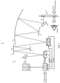
- FIG. 1 shows an augmented reality display system 1 which may be incorporated into a head mounted display worn by a user.
- the augmented reality system 1 permits the user to view their surroundings together with virtual visual information overlaid on top of the view of their surroundings.
- the augmented reality display system 1 includes at least one waveguide 15 which is supported adjacent to the user's eye, and which serves to combine ambient light from the user's surroundings together with virtual visual information.
- the virtual visual information is represented here by an output RGB laser beam 30.
- Output RGB laser beam 30 is generated here by an optical module 2 that directs the output RGB laser beam 30 toward the waveguide 15.
- the virtual visual information is incoupled to the waveguide 15 by an input 16 of the waveguide 15; the resulting augmented reality visual information is outcoupled to the user via an output 17 of the waveguide 15.
- the waveguide 15 may be a diffractive based waveguide.
- the input 16 and output 17 may be planar diffractive gratings defined on the surface of the waveguide 15.
- the augmented reality display system 1 includes a fast axis microelectromechanical system (MEMS) micromirror 4 and a slow axis MEMS micromirror 5.
- MEMS microelectromechanical system
- the fast axis MEMS micromirror 4 is driven at resonance (e.g., at 22 KHz) by a drive signal DrvF while the slow axis MEMS micromirror 5 is driven linearly (e.g., at 60 Hz) by a drive signal DrvS.
- the fast axis MEMS micromirror 4 and slow axis MEMS micromirror 5 cooperate to cause scanning of the output RGB laser beam 30 in a raster pattern, with the fast axis MEMS micromirror 4 causing here the scanning along the horizontal axis of the raster pattern and the slow axis MEMS micromirror 5 causing the scanning along the vertical axis of the raster pattern.
- Each complete raster pattern drawn represents one frame of an image to be displayed when viewed by the human eye.
- the fast axis MEMS micromirror 4 scans the RGB laser beam 20 across a wide-angle span (e.g., wider than the angle that a typical fast axis MEMS micromirror would typically scan an incident beam along in such applications), and that the reflective surface of the fast axis MEMS micromirror 4 is greater in area than that of the slow axis MEMS micromirror 5.
- Control circuitry 3 generates the drive signals DrvF and DrvS for the MEMS micromirrors 4 and 5 based upon respective feedback sense signals SenseF and SenseS received from the MEMS micromirrors 4 and 5 so as to maintain the driving of the MEMS micromirrors 4 and 5 at desired opening angles.
- the control circuitry 3 generates control signals for a light source module 6 of the optical module 2, discussed below, causing the light source module 6 to suitably modulate the color and intensity of the individual components making up the combined RGB laser beam 20, in correlation with the positions of the MEMS micromirrors 4 and 5, so that the image frames formed appear as instructed by an input image stream.
- Light source module 6 generates a combined RGB (red, green, blue) laser beam 20 which is reflected by a folding mirror 7 toward the fast axis MEMS micromirror 4.
- the fast axis MEMS micromirror 4 defines an input pupil diameter of the RGB laser beam 20.
- the fast axis MEMS micromirror 4 reflects the RGB laser beam 20 toward a first mirror 8 having a reflective surface with a concave cross section.
- the first mirror 8 in turn reflects the RGB laser beam 20 toward a second mirror 9 having a reflective surface with a convex cross section, which in turn reflects the RGB laser beam 20 toward a third mirror 10 having a reflective surface with a concave cross section.
- the third mirror 10 reflects the RGB laser beam 20 toward the slow axis MEMS micromirror 5.
- the first, second and third mirrors 8, 9, and 10 serve to magnify the RGB laser beam 20, to thereby define an output pupil diameter of the RGB laser beam as it impinges upon the slow axis MEMS micromirror 5.
- the output pupil diameter may be larger than the input pupil diameter by a ratio of 2:1, so that ultimately the diameter of the beam spot of the output RGB laser beam 30 as it is incident upon the input 16 is magnified by that 2:1 factor.
- first, second and third mirrors 8, 9, and 10 Another benefit provided by the first, second and third mirrors 8, 9, and 10 is to lower the angle of incidence of the RGB laser beam 20 on the slow axis MEMS micromirror 5, lowering distortion in the final image produced.
- the slow axis MEMS micromirror 5 reflects the RGB laser beam 20 toward an Offner relay formed by a fourth mirror 11 and a fifth mirror 12.
- the slow axis MEMS micromirror 5 reflects the RGB laser beam 20 toward the fourth mirror 11, which has a reflective surface with a concave cross section.
- the fourth mirror 11 reflects the RGB laser beam 20 toward the fifth mirror 12, which has a reflective surface with a convex cross section.
- the fifth mirror 12 reflects the RGB laser beam 20 back toward the fourth mirror 11, which then reflects the RGB laser beam 20 toward a folding mirror 13.
- the folding mirror 13 in turn reflects the RGB laser beam as the output RGB laser beam 30 out of an exit aperture in the optical module 2 and into the input 16 of the waveguide 15.
- the waveguide 15 combines the output RGB laser beam 30 incoupled via the input 16 together with ambient light from the environment and outcouples the result as augmented reality visual information to the user (target) via the output 17.
- the increase in pupil size provided by the optical module 2 serves to reduce the constraints on the waveguide 15 design, providing for enhanced performance, such as enabling the possibility of adding virtual images across the user's entire field of view.
- the increase in pupil size also increases waveguide efficiency by lowering power requirements for high brightness applications.
- the optical module 2 design may differ from the embodiment shown in Figure 1a.
- the mirrors 8, 9, 10, 11, and 12 are described as having reflective surfaces, but in some instances, one or more of the mirrors 8, 9, 10, 11, and 12 may instead be refractive elements.
- one or more of the mirrors 8, 9, 10, 11, and 12 may instead be a total internal reflection (TIR) based optic (and in such a case, chromatic error correction is to be performed).
- TIR total internal reflection
- the augmented reality system 1 is described above with reference to having one such optical module 2 and one such waveguide 15, although it should be understood that it may instead include two such optical modules 2 and 2', and two such waveguides 15 and 15' so that one waveguide may be supported adjacent each of the user's eyes, as shown in FIG. 2 .
- the optical module 2 described above may be utilized in a light detection and ranging (LIDAR) system 50, as shown in FIG. 3 .
- the laser beam 20 is an infrared laser beam instead of a RGB laser beam, and the waveguide is not present.
- a light detector array 49 is added so that the time between emission of a pulse of the laser and detection of photons of that laser pulse that have reflected off an object and been detected by the detector can be determined by the control circuitry 3. Given this time of flight and with the understanding of where the laser beam was scanned at any instant in time, a three-dimensional map of objects in the field of view can be formed by the control circuitry 3 and utilized by hardware external to the LIDAR system 50.
Landscapes
- Physics & Mathematics (AREA)
- General Physics & Mathematics (AREA)
- Optics & Photonics (AREA)
- Engineering & Computer Science (AREA)
- Computer Networks & Wireless Communication (AREA)
- Radar, Positioning & Navigation (AREA)
- Remote Sensing (AREA)
- Multimedia (AREA)
- Signal Processing (AREA)
- Mechanical Optical Scanning Systems (AREA)
Abstract
An optical module (2) includes a fast-axis mirror (4) that scans a laser beam (20) along a fast-axis, a magnification mirror (8-10) set formed by three discrete mirrors shaped to magnify the laser beam as it is scanned along the fast-axis and reflect the laser beam after magnification toward a slow-axis mirror (5) that scans the laser beam along the slow-axis, and an Offner mirror relay (11, 12) that receives the laser beam as it is scanned along the slow-axis and reflects the laser beam out an exit aperture. The laser beam as output from the exit aperture is received at an input diffractive grating (16) of a diffractive waveguide (15) , with a user's eye being positioned adjacent an output diffractive grating (17) of the waveguide such that the user's eye views ambient light entering the waveguide from objects within the user's field of view as well as light from the laser beam as it exits the output diffractive grating.
Description
- This disclosure is related to the field of optics for use in laser scanning projectors.
- A laser scanning projector is a small, portable electronic device. Laser scanning projectors are typically paired to, or incorporated within, user devices such as smart glasses, smartphones, tablets, laptops, and head mounted devices, and are used to project images onto a projection surface, such as a wall, holographic surface, or inner display surface of virtual or augmented reality glasses. Laser scanning projectors are also used in depth sensing cameras and Light Detection and Ranging (LIDAR) systems.
- In the context of their use to project images, such laser scanning projectors typically include a projection subsystem and an optical module. The paired user device serves an image stream (e.g., a video stream) to the projection subsystem. The projection subsystem properly drives the optical module to project the image stream onto the projection surface for viewing.
- In the context of their use in depth sensing cameras and LIDAR systems, the projection subsystem properly drives the optical module to project light pulses at a scene that reflect off objects in the scene. By measuring the time between emission of an emitted laser pulse and detection of photons of that laser pulse that have reflected off an object and been detected by a detector, a time of flight of the emitted laser pulse is determined. Given this time of flight and with the understanding of the direction of emission of the laser pulse, a three-dimensional map of objects in the scene can be formed and utilized.
- Typical optical modules are comprised of a laser source and one or more microelectromechanical system (MEMS) mirrors that scan the laser beam produced by the laser source across the projection surface in a projection pattern.
- The projection subsystem controls the driving of the laser source and the driving of the movement of the one or more MEMS mirrors, and by modulating the laser beam according to its position on the projection surface, while the laser beam is scanned in the projection pattern, the image stream is displayed, or the light pulses are suitable directed at the scene.
- Augmented reality systems function by allowing ambient light from a user's surroundings together with directing light displaying additional visual information toward the user's eye. A waveguide may be used to accomplish this mixing of ambient light and additional visual information in a way that is visible to the user. For example, the waveguide may receive ambient light from the user's surroundings and may have the additional information displayed thereon through the use of a laser scanning projector. The field of view of the visual information displayed to the user through the waveguide is related to the pupil size of the light directed onto the waveguide by the laser scanning projector. The larger the pupil size of the light directed onto the waveguide, generally, the more efficient the waveguide and the better the performance provided by the waveguide.
- As such, further development into optical modules for generating the light with a larger pupil size is desired.
- Therefore, an aim of the present invention is to devise a solution that has high performances and small dimensions.
- According to the invention, an optical module and an optical system are provided, as defined in the attached claims.
- For the understanding of the present invention, embodiments thereof are now described, purely as a non-limitative examples, with reference to the enclosed drawings, wherein:
-
FIG. 1 is a diagrammatical representation of an augmented reality system disclosed herein. -
FIG. 2 is a block diagram of a second augmented reality system disclosed herein. -
FIG. 3 is a diagrammatical representation of a LIDAR system disclosed herein. - Disclosed herein is an optical system including an optical module, diffractive waveguide, and control circuitry. The optical module includes a RGB laser source configured to generate a combined RGB laser beam, a fast axis mirror arranged along a first path to receive the combined RGB laser beam and being drivable to scan the combined RGB laser beam along a fast axis, three optical surface magnification mirrors receiving the combined RGB laser beam as it is scanned along the fast axis and magnifying a diameter of the combined RGB laser beam, a slow axis mirror receiving the combined RGB laser beam after magnification and being drivable to scan the combined RGB laser beam along a slow axis, and an Offner mirror relay receiving the combined RGB laser beam as it is scanned along the slow axis and reflecting the combined RGB laser beam along a second path toward an exit aperture of the optical module. The diffractive waveguide has an input diffractive grating defined therein and is positioned such that the combined RGB laser beam passes from the exit aperture of the optical module into the input diffractive grating, the diffractive waveguide having an output diffractive grating to be positioned adjacent to a user's eye. The control circuitry is configured to modulate the RGB laser source according to input image data so that as the combined RGB laser beam is scanned along the fast axis and slow axis, images represented by the input image data are visible to the user's eye.
- A first folding mirror may be configured to receive the combined RGB laser beam from the RGB laser source and reflecting the combined RGB laser beam along the first path.
- A second folding mirror may be arranged along the second desired path and receive the combined RGB laser beam to reflect the combined RGB laser beam toward the exit aperture of the optical module.
- The three optical surface magnification mirrors may be a first concave mirror receiving the combined RGB laser beam as it is scanned along the fast axis and reflecting the combined RGB laser beam along a first internal path, a first convex mirror arranged along the first internal path to receive the combined RGB laser beam and reflecting the combined RGB laser beam along a second internal path, and a second concave mirror arranged along the second internal path to receive the combined RGB laser beam and reflecting the combined RGB laser beam toward the slow axis mirror. The first concave mirror, the first convex mirror, and the second concave mirror may cooperate to magnify the diameter of the combined RGB laser beam.
- The Offner mirror relay may include a spherical concave mirror receiving the combined RGB laser beam as it is scanned along the slow axis and reflecting the combined RGB laser beam along a third internal path, and a spherical convex mirror arranged along the third internal path to receive the combined RGB laser beam and reflecting the combined RGB laser beam along a fourth internal path different than the third internal path back toward the spherical concave mirror. The spherical concave mirror may reflect the combined RGB laser beam, as received along the fourth internal path, toward the exit aperture of the optical module.
- The fast axis mirror may be a first microelectromechanical system (MEMS) micromirror configured to be driveable at resonance to scan the combined RGB laser beam along the fast axis.
- The slow axis mirror may be a second MEMS micromirror configured to be driveable linearly to scan the combined RGB laser beam along the slow axis.
- Also disclosed herein is an optical module including a fast axis mirror arranged along a first path to receive a combined RGB laser beam and being drivable to scan the combined RGB laser beam along a fast axis, and three optical surface magnification mirrors receiving the combined RGB laser beam as it is scanned along the fast axis. The three optical surface magnification mirrors include a first concave mirror receiving the combined RGB laser beam as it is scanned along the fast axis and reflecting the combined RGB laser beam along a first internal path, a first convex mirror arranged along the first internal path to receive the combined RGB laser beam and reflecting the combined RGB laser beam along a second internal path, and a second concave mirror arranged along the second internal path to receive the combined RGB laser beam and reflecting the combined RGB laser beam toward the slow axis mirror. The first concave mirror, the first convex mirror, and the second concave mirror cooperate to magnify a diameter of the combined RGB laser beam. A slow axis mirror receives the combined RGB laser beam after magnification, the slow axis mirror being drivable to scan the combined RGB laser beam along a slow axis. An Offner mirror relay receives the combined RGB laser beam as it is scanned along the slow axis and reflecting the combined RGB laser beam along a second path toward an exit aperture of the optical module.
- The Offner mirror relay may be formed by a spherical concave mirror receiving the combined RGB laser beam as it is scanned along the slow axis and reflecting the combined RGB laser beam along a third internal path, and a spherical convex mirror arranged along the third internal path to receive the combined RGB laser beam, the spherical convex mirror reflecting the combined RGB laser beam along a fourth internal path different than the third internal path back toward the spherical concave mirror. The spherical concave mirror may reflect the combined RGB laser beam, as received along the fourth internal path, toward the exit aperture of the optical module.
- A RGB laser source may be configured to generate the combined RGB laser beam.
- A first folding mirror may be configured to receive the combined RGB laser beam from the RGB laser source and reflect the combined RGB laser beam along the first path.
- A second folding mirror may be arranged along the second desired path and receive the combined RGB laser beam to reflect the combined RGB laser beam toward the exit aperture of the optical module.
- The fast axis mirror may be a first microelectromechanical systems (MEMS) micromirror configured to be driveable at resonance to scan the combined RGB laser beam along the fast axis, and the slow axis mirror may be a second MEMS micromirror configured to be driveable linearly to scan the combined RGB laser beam along the slow axis.
- Also disclosed herein is an optical module including a RGB laser source configured to generate a combined RGB laser beam, a first folding mirror configured to receive the combined RGB laser beam from the RGB laser source and reflecting the combined RGB laser beam along the first path, a fast axis microelectromechanical systems (MEMS) mirror arranged along the first path to receive the combined RGB laser beam and being drivable to scan the combined RGB laser beam along a fast axis, three optical surface magnification mirrors receiving the combined RGB laser beam as it is scanned along the fast axis and magnifying a diameter of the combined RGB laser beam, a slow axis MEMS mirror receiving the combined RGB laser beam after magnification and being drivable to scan the combined RGB laser beam along a slow axis, an Offner mirror relay receiving the combined RGB laser beam as it is scanned along the slow axis and reflecting the combined RGB laser beam along a second path toward an exit aperture of the optical module, and a second folding mirror arranged along the second desired path and receiving the combined RGB laser beam to reflect the combined RGB laser beam toward the exit aperture of the optical module.
- The three optical surface magnification mirrors may be a first concave mirror receiving the combined RGB laser beam as it is scanned along the fast axis and reflecting the combined RGB laser beam along a first internal path, a first convex mirror arranged along the first internal path to receive the combined RGB laser beam and reflecting the combined RGB laser beam along a second internal path, and a second concave mirror arranged along the second internal path to receive the combined RGB laser beam and reflecting the combined RGB laser beam toward the slow axis mirror. The first concave mirror, the first convex mirror, and the second concave mirror may cooperate to magnify a diameter of the combined RGB laser beam;
- The Offner mirror relay may be formed by a spherical concave mirror receiving the combined RGB laser beam as it is scanned along the slow axis and reflecting the combined RGB laser beam along a third internal path, and a spherical convex mirror arranged along the third internal path to receive the combined RGB laser beam, the spherical convex mirror reflecting the combined RGB laser beam along a fourth internal path different than the third internal path back toward the spherical concave mirror.
- Also disclosed herein is an optical system including an optical module. The optical module includes a laser source configured to generate a laser beam, a first axis mirror arranged along a first path to receive the laser beam and being drivable to scan the laser beam along a first axis, three optical surface magnification mirrors receiving the laser beam as it is scanned along the first axis and magnifying a diameter of the laser beam, a second axis mirror receiving the laser beam after magnification and being drivable to scan the laser beam along a second axis, and an Offner mirror relay receiving the laser beam as it is scanned along the slow axis and reflecting the laser beam along a second path toward an exit aperture of the optical module.
- The three optical surface magnification mirrors may include a first concave mirror receiving the laser beam as it is scanned along the first axis and reflecting the laser beam along a first internal path, a first convex mirror arranged along the first internal path to receive the laser beam, the first convex mirror reflecting the laser beam along a second internal path, and a second concave mirror arranged along the second internal path to receive the laser beam, the second concave mirror reflecting the laser beam toward the second axis mirror. The first concave mirror, the first convex mirror, and the second concave mirror may cooperate to magnify the diameter of the laser beam.
- The Offner mirror relay may be formed by a spherical concave mirror receiving the laser beam as it is scanned along the second axis and reflecting the laser beam along a third internal path, and a spherical convex mirror arranged along the third internal path to receive the laser beam, the spherical convex mirror reflecting the laser beam along a fourth internal path different than the third internal path back toward the spherical concave mirror. The spherical concave mirror may reflect the laser beam, as received along the fourth internal path, toward the exit aperture of the optical module.
- A light detector may be configured to detect light from the laser beam that has reflected off an object after traveling through the exit aperture of the optical module, and control circuitry may be configured to determine elapsed time between emission of the laser beam and detection of the light by the light detector, and to determine distance to the object based upon the elapsed time.
- The first axis mirror may be a fast axis mirror, the first axis may be a fast axis, the second axis.
- In the description below, folding mirrors are disclosed.
- As known to the person skilled in the art, a folding mirror is a flat mirror that is mounted at a certain degree angle, such as about 45°, to an incident light beam. When mounted at about 45°, when a light beam strikes the flat mirror, it reflects at an angle equal to the angle of incidence so that the light beam is redirected at about a 90° angle.
- The angle of incidence is the angle between the incident beam and a line perpendicular to the mirror surface at the point of incidence. The angle of reflection is the angle between the reflected beam and the same perpendicular line. Since the folding mirror is a flat surface, the angle of reflection is also about 45° relative to the mirror surface, so that the reflected beam is approximately perpendicular to the incident beam.
-
FIG. 1 shows an augmentedreality display system 1 which may be incorporated into a head mounted display worn by a user. Theaugmented reality system 1 permits the user to view their surroundings together with virtual visual information overlaid on top of the view of their surroundings. - The augmented
reality display system 1 includes at least onewaveguide 15 which is supported adjacent to the user's eye, and which serves to combine ambient light from the user's surroundings together with virtual visual information. - The virtual visual information is represented here by an output
RGB laser beam 30. - Output
RGB laser beam 30 is generated here by anoptical module 2 that directs the outputRGB laser beam 30 toward thewaveguide 15. - The virtual visual information is incoupled to the
waveguide 15 by aninput 16 of thewaveguide 15; the resulting augmented reality visual information is outcoupled to the user via anoutput 17 of thewaveguide 15. - The
waveguide 15 may be a diffractive based waveguide. - The
input 16 andoutput 17 may be planar diffractive gratings defined on the surface of thewaveguide 15. - The augmented
reality display system 1 includes a fast axis microelectromechanical system (MEMS)micromirror 4 and a slow axis MEMS micromirror 5.For example, the fastaxis MEMS micromirror 4 is driven at resonance (e.g., at 22 KHz) by a drive signal DrvF while the slowaxis MEMS micromirror 5 is driven linearly (e.g., at 60 Hz) by a drive signal DrvS. - The fast
axis MEMS micromirror 4 and slowaxis MEMS micromirror 5 cooperate to cause scanning of the outputRGB laser beam 30 in a raster pattern, with the fastaxis MEMS micromirror 4 causing here the scanning along the horizontal axis of the raster pattern and the slowaxis MEMS micromirror 5 causing the scanning along the vertical axis of the raster pattern. Each complete raster pattern drawn represents one frame of an image to be displayed when viewed by the human eye. - Note here that the fast
axis MEMS micromirror 4 scans theRGB laser beam 20 across a wide-angle span (e.g., wider than the angle that a typical fast axis MEMS micromirror would typically scan an incident beam along in such applications), and that the reflective surface of the fastaxis MEMS micromirror 4 is greater in area than that of the slowaxis MEMS micromirror 5. -
Control circuitry 3 generates the drive signals DrvF and DrvS for theMEMS micromirrors MEMS micromirrors MEMS micromirrors - The
control circuitry 3 generates control signals for alight source module 6 of theoptical module 2, discussed below, causing thelight source module 6 to suitably modulate the color and intensity of the individual components making up the combinedRGB laser beam 20, in correlation with the positions of theMEMS micromirrors -
Light source module 6 generates a combined RGB (red, green, blue)laser beam 20 which is reflected by afolding mirror 7 toward the fastaxis MEMS micromirror 4. The fastaxis MEMS micromirror 4 defines an input pupil diameter of theRGB laser beam 20. - In the embodiment of
Figure 1 , the fastaxis MEMS micromirror 4 reflects theRGB laser beam 20 toward afirst mirror 8 having a reflective surface with a concave cross section. Thefirst mirror 8 in turn reflects theRGB laser beam 20 toward a second mirror 9 having a reflective surface with a convex cross section, which in turn reflects theRGB laser beam 20 toward athird mirror 10 having a reflective surface with a concave cross section. Thethird mirror 10 reflects theRGB laser beam 20 toward the slowaxis MEMS micromirror 5. - Collectively, the first, second and
third mirrors RGB laser beam 20, to thereby define an output pupil diameter of the RGB laser beam as it impinges upon the slowaxis MEMS micromirror 5. The output pupil diameter may be larger than the input pupil diameter by a ratio of 2:1, so that ultimately the diameter of the beam spot of the outputRGB laser beam 30 as it is incident upon theinput 16 is magnified by that 2:1 factor. - Another benefit provided by the first, second and
third mirrors RGB laser beam 20 on the slowaxis MEMS micromirror 5, lowering distortion in the final image produced. - The slow
axis MEMS micromirror 5 reflects theRGB laser beam 20 toward an Offner relay formed by afourth mirror 11 and afifth mirror 12. - In particular, the slow
axis MEMS micromirror 5 reflects theRGB laser beam 20 toward thefourth mirror 11, which has a reflective surface with a concave cross section. Thefourth mirror 11 reflects theRGB laser beam 20 toward thefifth mirror 12, which has a reflective surface with a convex cross section. Thefifth mirror 12 reflects theRGB laser beam 20 back toward thefourth mirror 11, which then reflects theRGB laser beam 20 toward afolding mirror 13. Thefolding mirror 13 in turn reflects the RGB laser beam as the outputRGB laser beam 30 out of an exit aperture in theoptical module 2 and into theinput 16 of thewaveguide 15. - As explained, the
waveguide 15 combines the outputRGB laser beam 30 incoupled via theinput 16 together with ambient light from the environment and outcouples the result as augmented reality visual information to the user (target) via theoutput 17. - The increase in pupil size provided by the
optical module 2 serves to reduce the constraints on thewaveguide 15 design, providing for enhanced performance, such as enabling the possibility of adding virtual images across the user's entire field of view. The increase in pupil size also increases waveguide efficiency by lowering power requirements for high brightness applications. - The
optical module 2 design may differ from the embodiment shown in Figure 1a. For example, themirrors mirrors - It may also be possible to remove one of the mirrors (for example, third mirror 10).
- In addition, one or more of the
mirrors - The
augmented reality system 1 is described above with reference to having one suchoptical module 2 and onesuch waveguide 15, although it should be understood that it may instead include two suchoptical modules 2 and 2', and twosuch waveguides 15 and 15' so that one waveguide may be supported adjacent each of the user's eyes, as shown inFIG. 2 . - The
optical module 2 described above may be utilized in a light detection and ranging (LIDAR)system 50, as shown inFIG. 3 . In such a case, thelaser beam 20 is an infrared laser beam instead of a RGB laser beam, and the waveguide is not present. - A
light detector array 49 is added so that the time between emission of a pulse of the laser and detection of photons of that laser pulse that have reflected off an object and been detected by the detector can be determined by thecontrol circuitry 3. Given this time of flight and with the understanding of where the laser beam was scanned at any instant in time, a three-dimensional map of objects in the field of view can be formed by thecontrol circuitry 3 and utilized by hardware external to theLIDAR system 50. - Finally, it is clear that modifications and variations may be made to what has been described and illustrated herein, without thereby departing from the scope of this disclosure, as defined in the annexed claims.
- Examples of the present disclosure may be summarized as follows.
- 1. An optical system, comprising:
- an optical module comprising:
- a RGB laser source configured to generate a combined RGB laser beam;
- a fast axis mirror arranged along a first path to receive the combined RGB laser beam, the fast axis mirror being drivable to scan the combined RGB laser beam along a fast axis;
- three optical surface magnification mirrors receiving the combined RGB laser beam as it is scanned along the fast axis and magnifying a diameter of the combined RGB laser beam;
- a slow axis mirror receiving the combined RGB laser beam after magnification, the slow axis mirror being drivable to scan the combined RGB laser beam along a slow axis; and
- an Offner mirror relay receiving the combined RGB laser beam as it is scanned along the slow axis and reflecting the combined RGB laser beam along a second path toward an exit aperture of the optical module;
- a diffractive waveguide having an input diffractive grating defined therein and being positioned such that the combined RGB laser beam passes from the exit aperture of the optical module into the input diffractive grating, the diffractive waveguide having an output diffractive grating to be positioned adjacent to a user's eye; and
- control circuitry configured to modulate the RGB laser source according to input image data so that as the combined RGB laser beam is scanned along the fast axis and slow axis, images represented by the input image data are visible to the user's eye.
- an optical module comprising:
- 2. The optical system of example 1, further comprising:
a first folding mirror configured to receive the combined RGB laser beam from the RGB laser source and reflecting the combined RGB laser beam along the first path. - 3. The optical system of example 1, further comprising:
a second folding mirror arranged along the second desired path and receiving the combined RGB laser beam to reflect the combined RGB laser beam toward the exit aperture of the optical module. - 4. The optical system of example 1, wherein the three optical surface magnification mirrors comprise:
- a first concave mirror receiving the combined RGB laser beam as it is scanned along the fast axis and reflecting the combined RGB laser beam along a first internal path;
- a first convex mirror arranged along the first internal path to receive the combined RGB laser beam, the first convex mirror reflecting the combined RGB laser beam along a second internal path; and
- a second concave mirror arranged along the second internal path to receive the combined RGB laser beam, the second concave mirror reflecting the combined RGB laser beam toward the slow axis mirror;
- wherein the first concave mirror, the first convex mirror, and the second concave mirror cooperate to magnify the diameter of the combined RGB laser beam.
- 5. The optical system of example 1, wherein the Offner mirror relay comprises:
- a spherical concave mirror receiving the combined RGB laser beam as it is scanned along the slow axis and reflecting the combined RGB laser beam along a third internal path; and
- a spherical convex mirror arranged along the third internal path to receive the combined RGB laser beam, the spherical convex mirror reflecting the combined RGB laser beam along a fourth internal path different than the third internal path back toward the spherical concave mirror;
- wherein the spherical concave mirror reflects the combined RGB laser beam, as received along the fourth internal path, toward the exit aperture of the optical module.
- 6. The optical system of example 1,
- wherein the fast axis mirror is a first microelectromechanical system (MEMS) micromirror configured to be driveable at resonance to scan the combined RGB laser beam along the fast axis; and
- wherein the slow axis mirror is a second MEMS micromirror configured to be driveable linearly to scan the combined RGB laser beam along the slow axis.
- 7. An optical module, comprising:
- a fast axis mirror arranged along a first path to receive a combined RGB laser beam, the fast axis mirror being drivable to scan the combined RGB laser beam along a fast axis;
- three optical surface magnification mirrors receiving the combined RGB laser beam as it is scanned along the fast axis, wherein the three optical surface magnification mirrors comprise:
- a first concave mirror receiving the combined RGB laser beam as it is scanned along the fast axis and reflecting the combined RGB laser beam along a first internal path;
- a first convex mirror arranged along the first internal path to receive the combined RGB laser beam, the first convex mirror reflecting the combined RGB laser beam along a second internal path; and
- a second concave mirror arranged along the second internal path to receive the combined RGB laser beam, the second concave mirror reflecting the combined RGB laser beam toward the slow axis mirror;
- wherein the first concave mirror, the first convex mirror, and the second concave mirror cooperate to magnify a diameter of the combined RGB laser beam;
- a slow axis mirror receiving the combined RGB laser beam after magnification, the slow axis mirror being drivable to scan the combined RGB laser beam along a slow axis; and
- an Offner mirror relay receiving the combined RGB laser beam as it is scanned along the slow axis and reflecting the combined RGB laser beam along a second path toward an exit aperture of the optical module.
- 8. The optical module of example 7, wherein the Offner mirror relay comprises:
- a spherical concave mirror receiving the combined RGB laser beam as it is scanned along the slow axis and reflecting the combined RGB laser beam along a third internal path; and
- a spherical convex mirror arranged along the third internal path to receive the combined RGB laser beam, the spherical convex mirror reflecting the combined RGB laser beam along a fourth internal path different than the third internal path back toward the spherical concave mirror;
- wherein the spherical concave mirror reflects the combined RGB laser beam, as received along the fourth internal path, toward the exit aperture of the optical module.
- 9. The optical module of example 7, further comprising a RGB laser source configured to generate the combined RGB laser beam.
- 10. The optical module of example 7, further comprising:
a first folding mirror configured to receive the combined RGB laser beam from the RGB laser source and reflecting the combined RGB laser beam along the first path. - 11. The optical module of example 7, further comprising:
a second folding mirror arranged along the second desired path and receiving the combined RGB laser beam to reflect the combined RGB laser beam toward the exit aperture of the optical module. - 12. The optical module of example 7,
- wherein the fast axis mirror is a first microelectromechanical systems (MEMS) micromirror configured to be driveable at resonance to scan the combined RGB laser beam along the fast axis; and
- wherein the slow axis mirror is a second MEMS micromirror configured to be driveable linearly to scan the combined RGB laser beam along the slow axis.
- 13. An optical module, comprising:
- a RGB laser source configured to generate a combined RGB laser beam;
- a first folding mirror configured to receive the combined RGB laser beam from the RGB laser source and reflecting the combined RGB laser beam along the first path; and
- a fast axis microelectromechanical systems (MEMS) mirror arranged along the first path to receive the combined RGB laser beam, the fast axis mirror being drivable to scan the combined RGB laser beam along a fast axis;
- three optical surface magnification mirrors receiving the combined RGB laser beam as it is scanned along the fast axis and magnifying a diameter of the combined RGB laser beam;
- a slow axis MEMS mirror receiving the combined RGB laser beam after magnification, the slow axis mirror being drivable to scan the combined RGB laser beam along a slow axis;
- an Offner mirror relay receiving the combined RGB laser beam as it is scanned along the slow axis and reflecting the combined RGB laser beam along a second path toward an exit aperture of the optical module; and
- a second folding mirror arranged along the second desired path and receiving the combined RGB laser beam to reflect the combined RGB laser beam toward the exit aperture of the optical module.
- 14. The optical module of example 13, wherein the three optical surface magnification mirrors comprise:
- a first concave mirror receiving the combined RGB laser beam as it is scanned along the fast axis and reflecting the combined RGB laser beam along a first internal path;
- a first convex mirror arranged along the first internal path to receive the combined RGB laser beam, the first convex mirror reflecting the combined RGB laser beam along a second internal path; and
- a second concave mirror arranged along the second internal path to receive the combined RGB laser beam, the second concave mirror reflecting the combined RGB laser beam toward the slow axis mirror;
- wherein the first concave mirror, the first convex mirror, and the second concave mirror cooperate to magnify a diameter of the combined RGB laser beam;
- 15. The optical module of example 13, wherein the Offner mirror relay comprises:
- a spherical concave mirror receiving the combined RGB laser beam as it is scanned along the slow axis and reflecting the combined RGB laser beam along a third internal path; and
- a spherical convex mirror arranged along the third internal path to receive the combined RGB laser beam, the spherical convex mirror reflecting the combined RGB laser beam along a fourth internal path different than the third internal path back toward the spherical concave mirror.
- 16. An optical system, comprising:
an optical module comprising:- a laser source configured to generate a laser beam;
- a first axis mirror arranged along a first path to receive the laser beam, the first axis mirror being drivable to scan the laser beam along a first axis;
- three optical surface magnification mirrors receiving the laser beam as it is scanned along the first axis and magnifying a diameter of the laser beam;
- a second axis mirror receiving the laser beam after magnification, the second axis mirror being drivable to scan the laser beam along a second axis; and
- an Offner mirror relay receiving the laser beam as it is scanned along the slow axis and reflecting the laser beam along a second path toward an exit aperture of the optical module.
- 17. The optical system of example 16, wherein the three optical surface magnification mirrors comprise:
- a first concave mirror receiving the laser beam as it is scanned along the first axis and reflecting the laser beam along a first internal path;
- a first convex mirror arranged along the first internal path to receive the laser beam, the first convex mirror reflecting the laser beam along a second internal path; and
- a second concave mirror arranged along the second internal path to receive the laser beam, the second concave mirror reflecting the laser beam toward the second axis mirror;
- wherein the first concave mirror, the first convex mirror, and the second concave mirror cooperate to magnify the diameter of the laser beam.
- 18. The optical system of example 16, wherein the Offner mirror relay comprises:
- a spherical concave mirror receiving the laser beam as it is scanned along the second axis and reflecting the laser beam along a third internal path; and
- a spherical convex mirror arranged along the third internal path to receive the laser beam, the spherical convex mirror reflecting the laser beam along a fourth internal path different than the third internal path back toward the spherical concave mirror;
- wherein the spherical concave mirror reflects the laser beam, as received along the fourth internal path, toward the exit aperture of the optical module.
- 19. The optical system of example 16, further comprising:
- a light detector configured to detect light from the laser beam that has reflected off an object after traveling through the exit aperture of the optical module; and
- control circuitry configured to determine elapsed time between emission of the laser beam and detection of the light by the light detector, and to determine distance to the object based upon the elapsed time.
- 20. The optical system of example 16, wherein the first axis mirror is a fast axis mirror; wherein the first axis is a fast axis; wherein the second axis mirror is a slow axis mirror; and wherein the second axis is a slow axis.
Claims (13)
- An optical module (2) comprising:a first axis mirror (4) arranged along a first path to receive a combined RGB laser beam (20), the first axis mirror being drivable to scan the combined RGB laser beam along a first axis;three optical surface magnification mirrors (8-10) receiving the combined RGB laser beam (20) as it is scanned along the first axis and magnifying a diameter of the combined RGB laser beam (20);a second axis mirror (5) receiving the combined RGB laser beam after magnification, the second axis mirror being drivable to scan the combined RGB laser beam along a second axis; andan Offner mirror relay (11, 12) receiving the combined RGB laser beam as it is scanned along the second axis and reflecting a resulting combined RGB laser beam (30) along a second path toward an exit aperture of the optical module.
- The optical system of claim 1, wherein the three optical surface magnification mirrors comprise:a first concave mirror (8) receiving the combined RGB laser beam (20) as it is scanned along the first axis and reflecting the combined RGB laser beam along a first internal path;a first convex mirror (9) arranged along the first internal path to receive the combined RGB laser beam, the first convex mirror reflecting the combined RGB laser beam along a second internal path; anda second concave mirror (10) arranged along the second internal path to receive the combined RGB laser beam, the second concave mirror reflecting the combined RGB laser beam toward the slow axis mirror;wherein the first concave mirror (8), the first convex mirror, (9) and the second concave mirror (10) cooperate to magnify a diameter of the combined RGB laser beam.
- The optical module of claim 1 or 2, wherein the Offner mirror relay comprises:a spherical concave mirror (11) receiving the combined RGB laser beam (20) as it is scanned along the second axis and reflecting the combined RGB laser beam along a third internal path; anda spherical convex mirror (12) arranged along the third internal path to receive the combined RGB laser beam, the spherical convex mirror reflecting the combined RGB laser beam along a fourth internal path different than the third internal path back toward the spherical concave mirror (11);wherein the spherical concave mirror (11) reflects the combined RGB laser beam, as received along the fourth internal path, toward the exit aperture of the optical module. (2)
- The optical module of any of claims 1-3, further comprising a RGB laser source (6) configured to generate the combined RGB laser beam (20).
- The optical module of the preceding claim, further comprising:
a source folding mirror (7) configured to receive the combined RGB laser beam (20) from the RGB laser source (6) and reflecting the combined RGB laser beam along the first path. - The optical module of any of claims 1-5, further comprising:
an exit folding mirror (13) arranged along the second desired path and receiving the combined RGB laser beam to reflect the resulting combined RGB laser beam (30) toward the exit aperture of the optical module (2). - The optical module of any of claims 1-6,
wherein the first axis mirror (4) is a fast axis mirror; the first axis is a fast axis; the second axis mirror (5) is a slow axis mirror; and the second axis is a slow axis. - The optical module of the preceding claim,wherein the fast axis mirror (4) is a first MEMS micromirror configured to be driveable at resonance to scan the combined RGB laser beam (20) along the fast axis; andthe slow axis mirror (5) is a second MEMS micromirror configured to be driveable linearly to scan the combined RGB laser beam along the slow axis.
- An optical system, comprising:the optical module (2) according to any of the preceding claims; a waveguide (15) having an input (16) defined therein and being positioned such that the resulting combined RGB laser beam (30) passes from the exit aperture of the optical module (2) into the input, the waveguide having an output (17) to be positioned adjacent to a user's eye; andcontrol circuitry (3) configured to modulate the RGB laser source according to input image data so that as the combined RGB laser beam is scanned along the first axis and second axis, images represented by the input image data are visible to the user's eye.
- The optical system of the preceding claim, further comprising:a light detector (49) configured to detect light from the laser beam that has reflected off an object after traveling through the exit aperture of the optical module (2); andcontrol circuitry (3) configured to determine elapsed time between emission of the laser beam and detection of the light by the light detector, and to determine distance to the object based upon the elapsed time.
- The optical system of claim 9 or 10, wherein the waveguide (15) is a diffractive based waveguide.
- The optical system of the preceding claim, wherein the input of the diffractive waveguide (15) is an input diffractive grating (16) and the output of the diffractive waveguide is output diffractive grating (17).
- The optical system of the preceding claim, wherein the input diffractive grating (16) and the output diffractive grating (17) are planar diffractive gratings defined on the surface of the waveguide (15).
Applications Claiming Priority (1)
| Application Number | Priority Date | Filing Date | Title |
|---|---|---|---|
| US17/699,958 US12405457B2 (en) | 2022-03-21 | 2022-03-21 | Reflective pupil relay optics for mems scanning system |
Publications (1)
| Publication Number | Publication Date |
|---|---|
| EP4249987A1 true EP4249987A1 (en) | 2023-09-27 |
Family
ID=85556792
Family Applications (1)
| Application Number | Title | Priority Date | Filing Date |
|---|---|---|---|
| EP23160863.9A Withdrawn EP4249987A1 (en) | 2022-03-21 | 2023-03-09 | Reflective pupil relay optics for mems scanning system |
Country Status (3)
| Country | Link |
|---|---|
| US (1) | US12405457B2 (en) |
| EP (1) | EP4249987A1 (en) |
| CN (2) | CN220569012U (en) |
Families Citing this family (3)
| Publication number | Priority date | Publication date | Assignee | Title |
|---|---|---|---|---|
| US12405457B2 (en) * | 2022-03-21 | 2025-09-02 | Stmicroelectronics International N.V. | Reflective pupil relay optics for mems scanning system |
| US12416802B2 (en) * | 2022-04-01 | 2025-09-16 | Stmicroelectronics International N.V. | Scanner laser optics for LIDAR |
| EP4605793A1 (en) * | 2022-09-21 | 2025-08-27 | Eyejets Ltd. | Optical device suitable for illuminating the retina |
Citations (3)
| Publication number | Priority date | Publication date | Assignee | Title |
|---|---|---|---|---|
| US20180299666A1 (en) * | 2017-04-17 | 2018-10-18 | Microvision, Inc. | Scanning Laser Devices with Reduced Exit Pupil Disparity |
| US10969675B1 (en) * | 2019-06-10 | 2021-04-06 | Facebook Technologies, Llc | Optical assemblies having scanning reflectors for projecting augmented reality content |
| US20210227187A1 (en) * | 2020-01-22 | 2021-07-22 | Magic Leap, Inc. | Two mirror scanning relay optics |
Family Cites Families (6)
| Publication number | Priority date | Publication date | Assignee | Title |
|---|---|---|---|---|
| US8427744B2 (en) * | 2009-10-12 | 2013-04-23 | Raytheon Company | All-reflective relayed focal telescope derived from the first two mirrors of an afocal three-mirror anastigmat |
| JP6035793B2 (en) * | 2012-03-14 | 2016-11-30 | ソニー株式会社 | Image display device and image generation device |
| US9250445B2 (en) * | 2012-08-08 | 2016-02-02 | Carol Ann Tosaya | Multiple-pixel-beam retinal displays |
| US10394034B2 (en) * | 2017-08-15 | 2019-08-27 | Microsoft Technology Licensing, Llc | Eye-tracking with MEMS scanning and optical relay |
| US10921580B2 (en) | 2018-03-07 | 2021-02-16 | Microsoft Technology Licensing, Llc | Systems and methods of increasing pupil size in a display system |
| US12405457B2 (en) * | 2022-03-21 | 2025-09-02 | Stmicroelectronics International N.V. | Reflective pupil relay optics for mems scanning system |
-
2022
- 2022-03-21 US US17/699,958 patent/US12405457B2/en active Active
-
2023
- 2023-03-09 EP EP23160863.9A patent/EP4249987A1/en not_active Withdrawn
- 2023-03-20 CN CN202320537774.2U patent/CN220569012U/en active Active
- 2023-03-20 CN CN202310266951.2A patent/CN116794836A/en active Pending
Patent Citations (3)
| Publication number | Priority date | Publication date | Assignee | Title |
|---|---|---|---|---|
| US20180299666A1 (en) * | 2017-04-17 | 2018-10-18 | Microvision, Inc. | Scanning Laser Devices with Reduced Exit Pupil Disparity |
| US10969675B1 (en) * | 2019-06-10 | 2021-04-06 | Facebook Technologies, Llc | Optical assemblies having scanning reflectors for projecting augmented reality content |
| US20210227187A1 (en) * | 2020-01-22 | 2021-07-22 | Magic Leap, Inc. | Two mirror scanning relay optics |
Non-Patent Citations (1)
| Title |
|---|
| DE WIT GERARD C. ET AL: "Offner-type pupil relay optics for a scanning system", LASER-BASED MICRO- AND NANOPACKAGING AND ASSEMBLY II, vol. 2774, 23 August 1996 (1996-08-23), pages 553 - 561, XP093067420, ISSN: 0277-786X, Retrieved from the Internet <URL:http://dx.doi.org/10.1117/12.246702> DOI: 10.1117/12.246702 * |
Also Published As
| Publication number | Publication date |
|---|---|
| US12405457B2 (en) | 2025-09-02 |
| CN220569012U (en) | 2024-03-08 |
| CN116794836A (en) | 2023-09-22 |
| US20230296868A1 (en) | 2023-09-21 |
Similar Documents
| Publication | Publication Date | Title |
|---|---|---|
| US11204503B2 (en) | Method and system for large field of view display with scanning mirror having optical power | |
| US12405457B2 (en) | Reflective pupil relay optics for mems scanning system | |
| JP2950306B2 (en) | Image display device | |
| US9247221B2 (en) | Scanning type projector | |
| CN109302594B (en) | Projection display device comprising an eye tracker | |
| KR100765765B1 (en) | Projector / Projection Display Unit | |
| US20180284441A1 (en) | Wide field head mounted display | |
| JP2007219562A (en) | Virtual retina display with fiber optic point source | |
| US20130003021A1 (en) | Beam Combiner for Scanned Beam Display or the Like | |
| US7190497B2 (en) | Scanning type image display optical system, scanning type image display apparatus, and image display system | |
| US12360377B2 (en) | Light projector module | |
| WO2022160962A1 (en) | Laser display module and head-mounted display apparatus | |
| CN112513718A (en) | Method and system for RGB luminaire | |
| JP4332780B2 (en) | Display device | |
| US11460703B2 (en) | Laser optical projection module and wearable device having the same | |
| CN108152951B (en) | Head-mounted display device | |
| US20230314791A1 (en) | Scanner laser optics for lidar | |
| JP4639691B2 (en) | Optical scanning device and image display device | |
| KR100424767B1 (en) | Apparatus for tracing image | |
| US20220140571A1 (en) | Compact optical module | |
| JP2002196260A (en) | Observation optical system and optical equipment | |
| US20220203829A1 (en) | Projection optical system and head-up display device mounted on automobile | |
| JP2024008215A (en) | image projection device | |
| KR20010000463A (en) | Device of Laser Display |
Legal Events
| Date | Code | Title | Description |
|---|---|---|---|
| PUAI | Public reference made under article 153(3) epc to a published international application that has entered the european phase |
Free format text: ORIGINAL CODE: 0009012 |
|
| STAA | Information on the status of an ep patent application or granted ep patent |
Free format text: STATUS: THE APPLICATION HAS BEEN PUBLISHED |
|
| AK | Designated contracting states |
Kind code of ref document: A1 Designated state(s): AL AT BE BG CH CY CZ DE DK EE ES FI FR GB GR HR HU IE IS IT LI LT LU LV MC ME MK MT NL NO PL PT RO RS SE SI SK SM TR |
|
| STAA | Information on the status of an ep patent application or granted ep patent |
Free format text: STATUS: THE APPLICATION IS DEEMED TO BE WITHDRAWN |
|
| 18D | Application deemed to be withdrawn |
Effective date: 20240328 |