EP4249972A1 - Multi-clad optical fibers - Google Patents
Multi-clad optical fibers Download PDFInfo
- Publication number
- EP4249972A1 EP4249972A1 EP23000042.4A EP23000042A EP4249972A1 EP 4249972 A1 EP4249972 A1 EP 4249972A1 EP 23000042 A EP23000042 A EP 23000042A EP 4249972 A1 EP4249972 A1 EP 4249972A1
- Authority
- EP
- European Patent Office
- Prior art keywords
- clad layer
- optical fiber
- clad
- silica
- ppm
- Prior art date
- Legal status (The legal status is an assumption and is not a legal conclusion. Google has not performed a legal analysis and makes no representation as to the accuracy of the status listed.)
- Pending
Links
Images


Classifications
-
- G—PHYSICS
- G02—OPTICS
- G02B—OPTICAL ELEMENTS, SYSTEMS OR APPARATUS
- G02B6/00—Light guides; Structural details of arrangements comprising light guides and other optical elements, e.g. couplings
- G02B6/02—Optical fibres with cladding with or without a coating
- G02B6/036—Optical fibres with cladding with or without a coating core or cladding comprising multiple layers
- G02B6/03616—Optical fibres characterised both by the number of different refractive index layers around the central core segment, i.e. around the innermost high index core layer, and their relative refractive index difference
- G02B6/03622—Optical fibres characterised both by the number of different refractive index layers around the central core segment, i.e. around the innermost high index core layer, and their relative refractive index difference having 2 layers only
-
- C—CHEMISTRY; METALLURGY
- C23—COATING METALLIC MATERIAL; COATING MATERIAL WITH METALLIC MATERIAL; CHEMICAL SURFACE TREATMENT; DIFFUSION TREATMENT OF METALLIC MATERIAL; COATING BY VACUUM EVAPORATION, BY SPUTTERING, BY ION IMPLANTATION OR BY CHEMICAL VAPOUR DEPOSITION, IN GENERAL; INHIBITING CORROSION OF METALLIC MATERIAL OR INCRUSTATION IN GENERAL
- C23C—COATING METALLIC MATERIAL; COATING MATERIAL WITH METALLIC MATERIAL; SURFACE TREATMENT OF METALLIC MATERIAL BY DIFFUSION INTO THE SURFACE, BY CHEMICAL CONVERSION OR SUBSTITUTION; COATING BY VACUUM EVAPORATION, BY SPUTTERING, BY ION IMPLANTATION OR BY CHEMICAL VAPOUR DEPOSITION, IN GENERAL
- C23C16/00—Chemical coating by decomposition of gaseous compounds, without leaving reaction products of surface material in the coating, i.e. chemical vapour deposition [CVD] processes
- C23C16/22—Chemical coating by decomposition of gaseous compounds, without leaving reaction products of surface material in the coating, i.e. chemical vapour deposition [CVD] processes characterised by the deposition of inorganic material, other than metallic material
- C23C16/30—Deposition of compounds, mixtures or solid solutions, e.g. borides, carbides, nitrides
- C23C16/40—Oxides
- C23C16/401—Oxides containing silicon
- C23C16/402—Silicon dioxide
-
- C—CHEMISTRY; METALLURGY
- C23—COATING METALLIC MATERIAL; COATING MATERIAL WITH METALLIC MATERIAL; CHEMICAL SURFACE TREATMENT; DIFFUSION TREATMENT OF METALLIC MATERIAL; COATING BY VACUUM EVAPORATION, BY SPUTTERING, BY ION IMPLANTATION OR BY CHEMICAL VAPOUR DEPOSITION, IN GENERAL; INHIBITING CORROSION OF METALLIC MATERIAL OR INCRUSTATION IN GENERAL
- C23C—COATING METALLIC MATERIAL; COATING MATERIAL WITH METALLIC MATERIAL; SURFACE TREATMENT OF METALLIC MATERIAL BY DIFFUSION INTO THE SURFACE, BY CHEMICAL CONVERSION OR SUBSTITUTION; COATING BY VACUUM EVAPORATION, BY SPUTTERING, BY ION IMPLANTATION OR BY CHEMICAL VAPOUR DEPOSITION, IN GENERAL
- C23C16/00—Chemical coating by decomposition of gaseous compounds, without leaving reaction products of surface material in the coating, i.e. chemical vapour deposition [CVD] processes
- C23C16/44—Chemical coating by decomposition of gaseous compounds, without leaving reaction products of surface material in the coating, i.e. chemical vapour deposition [CVD] processes characterised by the method of coating
- C23C16/453—Chemical coating by decomposition of gaseous compounds, without leaving reaction products of surface material in the coating, i.e. chemical vapour deposition [CVD] processes characterised by the method of coating passing the reaction gases through burners or torches, e.g. atmospheric pressure CVD
-
- G—PHYSICS
- G02—OPTICS
- G02B—OPTICAL ELEMENTS, SYSTEMS OR APPARATUS
- G02B6/00—Light guides; Structural details of arrangements comprising light guides and other optical elements, e.g. couplings
- G02B6/02—Optical fibres with cladding with or without a coating
- G02B6/02042—Multicore optical fibres
-
- G—PHYSICS
- G02—OPTICS
- G02B—OPTICAL ELEMENTS, SYSTEMS OR APPARATUS
- G02B6/00—Light guides; Structural details of arrangements comprising light guides and other optical elements, e.g. couplings
- G02B6/02—Optical fibres with cladding with or without a coating
- G02B6/02295—Microstructured optical fibre
- G02B6/02314—Plurality of longitudinal structures extending along optical fibre axis, e.g. holes
- G02B6/02319—Plurality of longitudinal structures extending along optical fibre axis, e.g. holes characterised by core or core-cladding interface features
- G02B6/02338—Structured core, e.g. core contains more than one material, non-constant refractive index distribution in core, asymmetric or non-circular elements in core unit, multiple cores, insertions between core and clad
-
- G—PHYSICS
- G02—OPTICS
- G02B—OPTICAL ELEMENTS, SYSTEMS OR APPARATUS
- G02B6/00—Light guides; Structural details of arrangements comprising light guides and other optical elements, e.g. couplings
- G02B6/02—Optical fibres with cladding with or without a coating
- G02B6/036—Optical fibres with cladding with or without a coating core or cladding comprising multiple layers
- G02B6/03694—Multiple layers differing in properties other than the refractive index, e.g. attenuation, diffusion, stress properties
Definitions
- Embodiments of the present disclosure relate to the field of optical fiber communications, and more particularly to a multi-clad optical fiber suitable for transmission of high-power light and the like, and an optical fiber module, a fiber laser, and a fiber amplifier having the optical fiber.
- optical fibers with small diameters are attracting attention as optical fibers that realize dense optical fiber cables.
- An optical fiber with a small diameter is in general an optical fiber in which a portion made of glass has a small diameter and the cladding diameter is small.
- optical fibers with small diameters also include one whose outer circumference with a coating, formed such that the coating covers the outer circumference of a cladding, included is small because the cladding diameter is small.
- An optical fiber cable consists of one or more optical fibers that use light to transfer information from one end of the one or more optical fibers to other.
- the one or more optical fibers are made by optical fiber preforms which are manufactured by depositing layers of specially formulated silicon dioxide using chemical vapor deposition (CVD) processes, such as outside vapor deposition (OVD) and vapor axial deposition (VAD) processes.
- CVD chemical vapor deposition
- OLED outside vapor deposition
- VAD vapor axial deposition
- Prior art US5076825A teaches about preform having three-layer construction, wherein a support layer made of a silica glass having a drawable temperature of at least 1800°C. In order to eliminate the problem that the cores of some adjacent optical fibers come into direct contact with each other i.e. to avoid sticking of cores of optical fiber.
- an optical fiber comprising: one or more cores and a clad enveloping the one or more cores.
- the clad further comprises at least two clad layers where the first clad layer is made of silica with less than 0.1% metallic impurity, and a second clad layer of the at least two clad layers is made of silica with greater than 0.1% metallic impurity.
- the core is either based of pure silica or of germanium doped silica.
- the first clad layer and second clad have OH content of less than 5 ppm.
- the optical fiber comprising a buffer clad layer between the first clad layer and the second clad layer.
- the first clad layer has a radius in a range of 10-20 microns.
- the first clad layer has less than 800 ppm OH content, less than 10 ppm aluminium and less than 2 ppm sodium.
- the second clad layer has less than 50 ppm OH content, more than 10 ppm aluminium and more than 2 ppm sodium.
- the at least two clad layers comprise the first clad layer and the second clad layer.
- the first clad layer surrounds one or more cores and the second clad layer surrounds the first clad layer.
- the first clad layer and the second clad layer are defined by a first purity level of silica and a second purity level of silica.
- the first purity level is higher than the second purity level.
- the first clad layer is made of type 3 silica and the second clad layer is made of type 1 silica or type 2 silica.
- An optical fiber refers to a medium associated with transmission of information over long distances in the form of light pulses.
- the optical fiber uses light to transmit voice and data communications over long distances when encapsulated in a jacket/sheath.
- the optical fiber may be of ITU.T G.657.A2 category.
- the optical fiber may be of ITU.T G.657.A1 or G.657.B3 or G.652.D or a multi-core or other suitable category.
- the ITU.T stands for International Telecommunication Union-Telecommunication Standardization Sector, is one of the three sectors of the ITU.
- the ITU is the United Nations specialized agency in the field of telecommunications and is responsible for studying technical, operating and tariff questions and issuing recommendations on them with a view to standardizing telecommunications on a worldwide basis.
- the optical fiber may be a bend insensitive fiber that has less degradation in optical properties or less increment in optical attenuation during multiple winding/unwinding operations of an optical fiber cable.
- core of an optical fiber as used herein is referred to as the innermost cylindrical structure present in the centre of the optical fiber, that is configured to guide the light rays inside the optical fiber.
- cladding of an optical fiber as used herein is referred to as one or more layered structure covering the core of an optical fiber from the outside, that is configured to possess a lower refractive index than the refractive index-of the core to facilitate total intemal reflection of light rays inside the optical fiber.
- Fig.1-4 are pictorial snapshots illustrating a multi-clad optical fiber in accordance with one or more embodiments of the present invention.
- the optical fiber 100, 200, 300, 400 may comprise one or more cores 102 and a clad enveloping the one or more cores 102.
- the one or more cores 102 are a light-carrying portion of the optical fiber 100, 200, 300, 400 using total internal reflection.
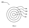
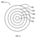
- Embodiments of the optical fiber represented in Fig. 1 , Fig. 2 ad Fig. 3 illustrates a -single core 102 having a plurality of clad represented by 104, 106, 108 and so on surrounding the core 102.
- Fig. 4 there are plurality of cores represented by 102 having plurality of clad 104 and 106 surrounding the core 102.
- the clad may comprise at least two clad layers 104, 106, 108 i.e., a first clad layer 104, a second clad layer 106 and a third clad layer 108.
- the first clad layer 104 may surround one or more cores 102
- the second clad layer 106 may surround the first clad layer 104
- the third clad layer 108 may surround the second clad layer 106.
- the optical fiber 100, 200, 300, 400 may comprise more than three clad layers or less than three clad layers.
- the first clad layer 104 of the at least two clad layers may be made of silica with less than 0.1% metallic impurity.
- the second clad layer 106 of the at least two clad layers may be made of silica with greater than 0.1% metallic impurity.
- the first clad layer 104 may be made of type 3 or type 4 silica
- the second clad layer 106 may be made of type 1 silica or type 2 silica
- the third clad layer 108 may be composed of type 1 silica or type 2 silica or type 3 silica or any combination of type 1 silica, type 2 silica, type 3 and type 4 silica.
- the type 1 silica or silica glasses may be produced from natural quartz by electric fusion under vacuum or under an inert gas atmosphere.
- the type 2 silica or silica glasses may be produced from quartz crystal powder by flame fusion (Verneuil process).
- the type 3 silica or silica glasses may be synthetic vitreous silicas produced by hydrolyzation of SiCl 4 (Silicon tetrachloride) when spraying into an oxygen-hydrogen flame.
- the type 3 silica or silica glass may be synthetic clear silica glass made by pyrolysis of SiCl 4 vapors blown into a plasma burner flame in the presence of oxygen.
- the core is either based on pure silica or of germanium doped silica wherein the content of OH has to be maintained at less than 1 ppm.
- the first clad layer which surrounds the core and the second clad layer which surrounds the first clad layer has OH content below 5ppm.
- the first clad layer is 10-20 microns in radius.
- the first clad layer 104 and the second clad layer 106 may be defined by a first purity level of silica and a second purity level of silica respectively. Further, the first purity level is higher than the second purity level.
- the first clad layer 104 may have less than 800 ppm OH content, less than 10 ppm aluminium and less than 5 ppm sodium.
- the second clad layer 106 may have less than 50 ppm OH content, more than 1ppm aluminium and more than 2 ppm sodium.
- the amount of OH content, aluminium and sodium in the first clad layer 104 and the second clad layer 106 may vary.
- other metallic impurities except aluminium and sodium may be used.
- the optical fiber 100, 200, 300, 400 remains dry so as to prevent signal deterioration as presence of moisture may cause attenuation or other adverse phenomena related to signal loss.
- electron probe micro-analyser and laser ablated ICP and Atomic absorption spectroscopy and Fourier transform infrared spectroscopy (FTIR) are techniques for the elemental analysis and quantification of the impurities present in the glass used for making optical fiber and thereby differentiating the different types of silica. This further helps in determining the type of silica to be used in an optical fiber as either a combination or individual for inner and outer clad.
- the optical fiber may further comprise a buffer clad layer 202, 302, 402 between the first clad layer 104 and the second clad layer 106.
- the buffer clad layer 202, 302, 402 may be composed of pure silica.
- multi-clad optical fibers manufactured by optical fiber preforms formed using a material that incurs low cost without reducing function, performance and quality of the optical fiber preforms, wherein the material is a combination of type 1, type 2, type 3 and type 4 silica forming optical fiber preform claddings.
- the material is a combination of type 1, type 2, type 3 and type 4 silica forming optical fiber preform claddings.
Landscapes
- Physics & Mathematics (AREA)
- Chemical & Material Sciences (AREA)
- General Physics & Mathematics (AREA)
- Optics & Photonics (AREA)
- Engineering & Computer Science (AREA)
- Chemical Kinetics & Catalysis (AREA)
- General Chemical & Material Sciences (AREA)
- Materials Engineering (AREA)
- Mechanical Engineering (AREA)
- Metallurgy (AREA)
- Organic Chemistry (AREA)
- Inorganic Chemistry (AREA)
- Plasma & Fusion (AREA)
- Glass Compositions (AREA)
Abstract
Description
- Embodiments of the present disclosure relate to the field of optical fiber communications, and more particularly to a multi-clad optical fiber suitable for transmission of high-power light and the like, and an optical fiber module, a fiber laser, and a fiber amplifier having the optical fiber.
- This application claims the benefit of
Indian Application No. 202211017573 titled "MULTI-CLAD OPTICAL FIBERS" filed by the applicant on March 26th, 2022 - The fields of data communications and telecommunications, optical fibers with small diameters are attracting attention as optical fibers that realize dense optical fiber cables. An optical fiber with a small diameter is in general an optical fiber in which a portion made of glass has a small diameter and the cladding diameter is small. Note that optical fibers with small diameters also include one whose outer circumference with a coating, formed such that the coating covers the outer circumference of a cladding, included is small because the cladding diameter is small.
- Optical fiber cables have secured an important position in building the optical network of modern communication systems across the globe. An optical fiber cable consists of one or more optical fibers that use light to transfer information from one end of the one or more optical fibers to other. The one or more optical fibers are made by optical fiber preforms which are manufactured by depositing layers of specially formulated silicon dioxide using chemical vapor deposition (CVD) processes, such as outside vapor deposition (OVD) and vapor axial deposition (VAD) processes. Such processes often utilize only a portion of a starting raw material due to limitations in deposition efficiency of the deposition processes. A lower deposition efficiency for the deposition processes leads to wastage of generated silica soot. Thus, resulting in significant increase in raw material cost. Some of the prior art references are given below:
- Prior art
US5076825A teaches about preform having three-layer construction, wherein a support layer made of a silica glass having a drawable temperature of at least 1800°C. In order to eliminate the problem that the cores of some adjacent optical fibers come into direct contact with each other i.e. to avoid sticking of cores of optical fiber. - Another prior art
US5090979A discloses a manufacturing process for an optical fiber preform whose cladding layer is doped in order to prevent loss of useful light from the optical fiber without reducing range of light wavelength over which the fiber provides effective transmission. - Yet another prior art
US20030026584A1 discloses an optical fiber having cladding made of nanoparticles in order to bear mechanical stresses and is hydrophobic in nature. - While the prior arts cover various solutions for the aforesaid drawbacks related to material wastage and high production cost. However, there still remains a need of material that can be used for producing the optical fiber preforms and incurs low cost without reducing function, performance and quality of the optical fiber preforms. In light of the above-stated discussion, there is a need to provide a technical solution that overcomes the aforementioned problems of the traditional optical fibers.
- According to the first aspect of the present disclosure, an optical fiber comprising: one or more cores and a clad enveloping the one or more cores. The clad further comprises at least two clad layers where the first clad layer is made of silica with less than 0.1% metallic impurity, and a second clad layer of the at least two clad layers is made of silica with greater than 0.1% metallic impurity.
- According to the second aspect of the present disclosure, the core is either based of pure silica or of germanium doped silica. Moreover, the first clad layer and second clad have OH content of less than 5 ppm.
- According to the third aspect of the present disclosure, the optical fiber comprising a buffer clad layer between the first clad layer and the second clad layer. The first clad layer has a radius in a range of 10-20 microns. The first clad layer has less than 800 ppm OH content, less than 10 ppm aluminium and less than 2 ppm sodium.
- According to the fourth aspect of the present disclosure, the second clad layer has less than 50 ppm OH content, more than 10 ppm aluminium and more than 2 ppm sodium.
- According to the fifth aspect of the present disclosure, the at least two clad layers comprise the first clad layer and the second clad layer. The first clad layer surrounds one or more cores and the second clad layer surrounds the first clad layer. In particular, the first clad layer and the second clad layer are defined by a first purity level of silica and a second purity level of silica. Moreover, the first purity level is higher than the second purity level. Further, the first clad layer is made of type 3 silica and the second clad layer is made of type 1 silica or type 2 silica.
- These and other aspects herein will be better appreciated and understood when considered in conjunction with the following description and the accompanying drawings. It should be understood, however, that the following descriptions are given by way of illustration and not of limitation. Many changes and modifications may be made within the scope of the disclosure herein without departing from the spirit thereof.
- To describe the technical solutions in the embodiments of the present disclosure or in the prior art more clearly, the following briefly describes the accompanying drawings required for describing the embodiments or the prior art. Apparently, the accompanying drawings in the following description merely show some embodiments of the present disclosure, and a person of ordinary skill in the art can derive other implementations from these accompanying drawings without creative efforts. All of the embodiments or the implementations shall fall within the protection scope of the present disclosure.
-
Fig. 1 is a pictorial snapshot illustrating a multi-clad optical fiber in accordance with an embodiment of the present invention; -
Fig. 2 is a pictorial snapshot illustrating a multi-clad optical fiber in accordance with another embodiment of the present invention; -
Fig. 3 is a pictorial snapshot illustrating a multi-clad optical fiber in accordance with yet another embodiment of the present invention; -
Fig. 4 is a pictorial snapshot illustrating a multi-clad optical fiber in accordance with yet another embodiment of the present invention. - The multi-clad optical fiber illustrated in the accompanying drawings, which like reference letters indicate corresponding parts in the various figures. It should be noted that the accompanying figure is intended to present illustrations of exemplary embodiments of the present invention. This figure is not intended to limit the scope of the present invention. It should also be noted that the accompanying figure is not necessarily drawn to scale.
- Those skilled in the art will be aware that the present disclosure is subject to variations and modifications other than those specifically described. It is to be understood that the present disclosure includes all such variations and modifications. The disclosure also includes all such steps, features, compositions, and compounds referred to or indicated- in this specification, individually or collectively, and any and all combinations of any or more of such steps or features.
- For convenience, before further description of the present disclosure, certain terms employed in the specification, and examples are collected here. These definitions should be read in the light of the remainder of the disclosure and understood as by a person of skill in the art. The terms used herein have the meanings recognized and known to those of skill in the art, however, for convenience and completeness, particular terms and their meanings are set forth below.
- The articles "a", "an" and "the" are used to refer to one or to more than one (i.e., to at least one) of the grammatical object of the article.
- The terms "comprise" and "comprising" are used in the inclusive, open sense, meaning that additional elements may be included. It is not intended to be construed as "consists of only". Throughout this specification, unless the context requires otherwise the word "comprise", and variations such as "comprises" and "comprising", will be understood to imply the inclusion of a stated element or step or group of element or steps but not the exclusion of any other element or step or group of element or steps.
- The term "including" is used to mean "including but not limited to". "Including" and "including but not limited to" are used interchangeably.
- An optical fiber refers to a medium associated with transmission of information over long distances in the form of light pulses. The optical fiber uses light to transmit voice and data communications over long distances when encapsulated in a jacket/sheath. The optical fiber may be of ITU.T G.657.A2 category. Alternatively, the optical fiber may be of ITU.T G.657.A1 or G.657.B3 or G.652.D or a multi-core or other suitable category. The ITU.T, stands for International Telecommunication Union-Telecommunication Standardization Sector, is one of the three sectors of the ITU. The ITU is the United Nations specialized agency in the field of telecommunications and is responsible for studying technical, operating and tariff questions and issuing recommendations on them with a view to standardizing telecommunications on a worldwide basis. The optical fiber may be a bend insensitive fiber that has less degradation in optical properties or less increment in optical attenuation during multiple winding/unwinding operations of an optical fiber cable.
- The term "core" of an optical fiber as used herein is referred to as the innermost cylindrical structure present in the centre of the optical fiber, that is configured to guide the light rays inside the optical fiber.
- The term "cladding" of an optical fiber as used herein is referred to as one or more layered structure covering the core of an optical fiber from the outside, that is configured to possess a lower refractive index than the refractive index-of the core to facilitate total intemal reflection of light rays inside the optical fiber.
- Terms multi-clad optical fibers and optical fibers are used interchangeably throughout the draft.
-
Fig.1-4 are pictorial snapshots illustrating a multi-clad optical fiber in accordance with one or more embodiments of the present invention. Theoptical fiber more cores 102 and a clad enveloping the one ormore cores 102. In particular, the one ormore cores 102 are a light-carrying portion of theoptical fiber Fig. 1 ,Fig. 2 adFig. 3 illustrates a -single core 102 having a plurality of clad represented by 104, 106, 108 and so on surrounding thecore 102. AndFig. 4 there are plurality of cores represented by 102 having plurality of clad 104 and 106 surrounding thecore 102. - Now simultaneously referring to
Fig.1- 4 . The clad may comprise at least twoclad layers clad layer 104, a secondclad layer 106 and a thirdclad layer 108. In particular, the firstclad layer 104 may surround one ormore cores 102, the secondclad layer 106 may surround the firstclad layer 104 and the thirdclad layer 108 may surround the secondclad layer 106. Further, it may be noted that theoptical fiber - In accordance with an embodiment of the present invention, the first
clad layer 104 of the at least two clad layers may be made of silica with less than 0.1% metallic impurity. And the secondclad layer 106 of the at least two clad layers may be made of silica with greater than 0.1% metallic impurity. - In accordance with an embodiment of the present invention, the first
clad layer 104 may be made of type 3 or type 4 silica, the secondclad layer 106 may be made of type 1 silica or type 2 silica, the thirdclad layer 108 may be composed of type 1 silica or type 2 silica or type 3 silica or any combination of type 1 silica, type 2 silica, type 3 and type 4 silica. Further, the type 1 silica or silica glasses may be produced from natural quartz by electric fusion under vacuum or under an inert gas atmosphere. The type 2 silica or silica glasses may be produced from quartz crystal powder by flame fusion (Verneuil process). The type 3 silica or silica glasses may be synthetic vitreous silicas produced by hydrolyzation of SiCl4 (Silicon tetrachloride) when spraying into an oxygen-hydrogen flame. The type 3 silica or silica glass may be synthetic clear silica glass made by pyrolysis of SiCl4 vapors blown into a plasma burner flame in the presence of oxygen. - In accordance with an embodiment of the present invention, the core is either based on pure silica or of germanium doped silica wherein the content of OH has to be maintained at less than 1 ppm. Further, the first clad layer which surrounds the core and the second clad layer which surrounds the first clad layer has OH content below 5ppm. The first clad layer is 10-20 microns in radius.
- In accordance with an embod4nentof-the present invention, the first
clad layer 104 and the secondclad layer 106 may be defined by a first purity level of silica and a second purity level of silica respectively. Further, the first purity level is higher than the second purity level. - In accordance with an embodiment of the present invention, the first
clad layer 104 may have less than 800 ppm OH content, less than 10 ppm aluminium and less than 5 ppm sodium. The secondclad layer 106 may have less than 50 ppm OH content, more than 1ppm aluminium and more than 2 ppm sodium. Alternatively, the amount of OH content, aluminium and sodium in the firstclad layer 104 and the secondclad layer 106 may vary. Alternatively, other metallic impurities except aluminium and sodium may be used. - In accordance with an embodiment of the present invention, due to the presence of OH content or group, the
optical fiber - In accordance with an embodiment of the present invention, electron probe micro-analyser (EPMA) and laser ablated ICP and Atomic absorption spectroscopy and Fourier transform infrared spectroscopy (FTIR) are techniques for the elemental analysis and quantification of the impurities present in the glass used for making optical fiber and thereby differentiating the different types of silica. This further helps in determining the type of silica to be used in an optical fiber as either a combination or individual for inner and outer clad.
- In accordance with an embodiment of the present invention, the optical fiber may further comprise a buffer clad
layer clad layer 104 and the secondclad layer 106. Further, the buffer cladlayer - Advantageously, multi-clad optical fibers manufactured by optical fiber preforms formed using a material that incurs low cost without reducing function, performance and quality of the optical fiber preforms, wherein the material is a combination of type 1, type 2, type 3 and type 4 silica forming optical fiber preform claddings. Further, due to the combination of silica clad layers and a reduced coating layer in the
optical fiber optical fiber - The foregoing description of specific embodiments of the presenit technology have been presented for purposes of illustration and description. They are not intended to be exhaustive or to limit the present technology to the precise forms disclosed, and obviously many modifications and variations are possible in light of the above teaching. The embodiments were chosen and described in order to best explain the principles of the present technology and its-practical application, to thereby enable others skilled in the art to best utilize the present technology and various embodiments with various modifications as are suited to the particular use contemplated. It is understood that various omissions and substitutions of equivalents are contemplated as circumstance may suggest or render expedient, but such are intended to cover the application or implementation without departing from the spirit or scope of the claims of the present technology.
- In a case that no conflict occurs, the embodiments in the present disclosure and the features in the embodiments may be mutually combined. The foregoing descriptions are merely specific implementations of the present disclosure but are not intended to limit the protection scope of the present disclosure. Any variation or replacement readily figured out by a person skilled in the art within the technical scope disclosed in the present disclosure shall fall within the protection scope of the present disclosure. Therefore, the protection scope of the present disclosure shall be subject to the protection scope of the claims.
Claims (15)
- An optical fiber (100, 200, 300, 400) characterized in that:one or more cores (102); anda clad enveloping the one or more cores (102), wherein the clad comprising at least two clad layers (104,106), wherein a first clad layer (104) of the at least two clad layers (104, 106)is made of silica with less than 0.1% metallic impurity, and a second clad layer (106) of the at least two clad layers (104, 106) is made of silica with greater than 0.1% metallic impurity.
- The optical fiber (100, 200, 300, 400) as claimed in claim 1, wherein the core (102) is either based of pure silica or of germanium doped silica.
- The optical fiber (100, 200, 300, 400) as claimed in claim 1, wherein the core (102) has less than 1 ppm OH content.
- The optical fiber (100, 200, 300, 400) as claimed in claim 1, wherein the first clad layer (104) and second clad (106) has OH content of less than 5 ppm.
- The optical fiber (100,200, 300, 400) as claimed in claim 1, wherein the first clad layer has a radius in a range of 10-20 microns.
- The optical fiber (100, 200, 300, 400) as claimed in claim 1, further comprising a buffer clad layer (202, 302, 402) between the first clad layer (104) and the second clad layer (106).
- The optical fiber (100, 200, 300, 400) as claimed in claim 1, wherein the first clad layer (104) has less than 800 ppm OH content.
- The optical fiber (100, 200, 300, 400) as claimed in claim 1, wherein the first clad layer (104) has less than 10 ppm aluminium and less than 2 ppm sodium.
- The optical fiber (100, 200, 300, 400) as claimed in claim 1, wherein the second clad - layer (106) has less than 50 ppm OH content.
- The optical fiber (100, 200, 300, 400) as claimed in claim 1, wherein the second clad layer (106) has more than 10 ppm aluminium and more than 2 ppm sodium.
- The optical fiber (100, 200, 300, 400) as claimed in claim 1 wherein the at least two clad layers comprise the first clad layer (104) and the second clad layer (106).
- The optical fiber (100, 200, 300, 400) as claimed in claim 11, wherein the first clad layer (104) surrounds the one or more cores (102) and the second clad layer (106) surrounds the first clad layer (104).
- The optical fiber (100, 200, 300, 400) as claimed in claim 1, wherein the first clad layer (104) and the second clad layer (106) are defined by a first purity level of silica and a second purity level of silica.
- The optical fiber (100, 200, 300, 400) as claimed in claim 1, wherein the first purity level is higher than the second purity level.
- The optical fiber (100, 200, 300, 400) as claimed in claim 1, wherein the first clad layer (104) is made of type 3 silica and the second clad layer (106) is made of type 1 silica or type 2 silica.
Priority Applications (1)
| Application Number | Priority Date | Filing Date | Title |
|---|---|---|---|
| EP26168522.6A EP4741893A3 (en) | 2022-03-26 | 2023-03-23 | Multi-clad optical fibers |
Applications Claiming Priority (1)
| Application Number | Priority Date | Filing Date | Title |
|---|---|---|---|
| IN202211017573 | 2022-03-26 |
Related Child Applications (1)
| Application Number | Title | Priority Date | Filing Date |
|---|---|---|---|
| EP26168522.6A Division EP4741893A3 (en) | 2022-03-26 | 2023-03-23 | Multi-clad optical fibers |
Publications (1)
| Publication Number | Publication Date |
|---|---|
| EP4249972A1 true EP4249972A1 (en) | 2023-09-27 |
Family
ID=85726391
Family Applications (2)
| Application Number | Title | Priority Date | Filing Date |
|---|---|---|---|
| EP23000042.4A Pending EP4249972A1 (en) | 2022-03-26 | 2023-03-23 | Multi-clad optical fibers |
| EP26168522.6A Pending EP4741893A3 (en) | 2022-03-26 | 2023-03-23 | Multi-clad optical fibers |
Family Applications After (1)
| Application Number | Title | Priority Date | Filing Date |
|---|---|---|---|
| EP26168522.6A Pending EP4741893A3 (en) | 2022-03-26 | 2023-03-23 | Multi-clad optical fibers |
Country Status (2)
| Country | Link |
|---|---|
| US (1) | US12596224B2 (en) |
| EP (2) | EP4249972A1 (en) |
Citations (7)
| Publication number | Priority date | Publication date | Assignee | Title |
|---|---|---|---|---|
| US5076825A (en) | 1982-03-01 | 1991-12-31 | Dainichi-Nippon Cables, Ltd. | Method of producing optical multiple fiber |
| US5090979A (en) | 1989-08-02 | 1992-02-25 | Compagnie Generale D'electricite | Method of manufacturing an optical fiber preform having doped cladding |
| US20030026584A1 (en) | 2001-06-20 | 2003-02-06 | Dov Ingman | Optical fiber with nano-particle cladding |
| EP1125152B1 (en) * | 1998-10-28 | 2004-12-22 | Minnesota Mining And Manufacturing Company | Light fibers and methods of producing the same |
| CN103760634A (en) * | 2014-01-27 | 2014-04-30 | 长飞光纤光缆股份有限公司 | Single mode fiber |
| CN103864291A (en) * | 2014-01-27 | 2014-06-18 | 长飞光纤光缆股份有限公司 | Single mode fiber preform and preparation method thereof |
| US9983352B2 (en) * | 2011-01-14 | 2018-05-29 | Gwangju Institute Of Science And Technology | Optical fiber having a cladding layer doped with metal nano-particles, coreless optical fiber, and method for manufacturing same |
Family Cites Families (7)
| Publication number | Priority date | Publication date | Assignee | Title |
|---|---|---|---|---|
| JP2006154707A (en) * | 2004-10-29 | 2006-06-15 | Shin Etsu Chem Co Ltd | Optical fiber |
| US8789393B2 (en) * | 2004-11-29 | 2014-07-29 | The Furukawa Electric Co., Ltd. | Optical fiber preform, method of manufacturing optical fiber preform, and method of manufacturing optical fiber |
| FR2893149B1 (en) * | 2005-11-10 | 2008-01-11 | Draka Comteq France | OPTICAL FIBER MONOMODE. |
| CN104898200B (en) * | 2015-06-25 | 2018-03-16 | 长飞光纤光缆股份有限公司 | A kind of ultralow decay single-mode fiber for adulterating optimization |
| CN107193080B (en) * | 2017-06-28 | 2020-05-05 | 长飞光纤光缆股份有限公司 | High bandwidth bend insensitive multimode optical fiber |
| CN107522396B (en) * | 2017-08-23 | 2019-12-24 | 成都富通光通信技术有限公司 | A kind of optical fiber and its preparation method |
| CN113848608B (en) * | 2020-06-28 | 2023-08-08 | 中天科技精密材料有限公司 | Single-mode optical fiber and preparation method thereof |
-
2023
- 2023-03-17 US US18/185,685 patent/US12596224B2/en active Active
- 2023-03-23 EP EP23000042.4A patent/EP4249972A1/en active Pending
- 2023-03-23 EP EP26168522.6A patent/EP4741893A3/en active Pending
Patent Citations (7)
| Publication number | Priority date | Publication date | Assignee | Title |
|---|---|---|---|---|
| US5076825A (en) | 1982-03-01 | 1991-12-31 | Dainichi-Nippon Cables, Ltd. | Method of producing optical multiple fiber |
| US5090979A (en) | 1989-08-02 | 1992-02-25 | Compagnie Generale D'electricite | Method of manufacturing an optical fiber preform having doped cladding |
| EP1125152B1 (en) * | 1998-10-28 | 2004-12-22 | Minnesota Mining And Manufacturing Company | Light fibers and methods of producing the same |
| US20030026584A1 (en) | 2001-06-20 | 2003-02-06 | Dov Ingman | Optical fiber with nano-particle cladding |
| US9983352B2 (en) * | 2011-01-14 | 2018-05-29 | Gwangju Institute Of Science And Technology | Optical fiber having a cladding layer doped with metal nano-particles, coreless optical fiber, and method for manufacturing same |
| CN103760634A (en) * | 2014-01-27 | 2014-04-30 | 长飞光纤光缆股份有限公司 | Single mode fiber |
| CN103864291A (en) * | 2014-01-27 | 2014-06-18 | 长飞光纤光缆股份有限公司 | Single mode fiber preform and preparation method thereof |
Also Published As
| Publication number | Publication date |
|---|---|
| EP4741893A2 (en) | 2026-05-13 |
| US12596224B2 (en) | 2026-04-07 |
| EP4741893A3 (en) | 2026-07-29 |
| US20230305224A1 (en) | 2023-09-28 |
Similar Documents
| Publication | Publication Date | Title |
|---|---|---|
| US8081854B2 (en) | Low bend loss optical fiber | |
| CN102798927B (en) | Single-mode fiber and manufacture method thereof | |
| JP5684109B2 (en) | Multi-core optical fiber | |
| JP5476125B2 (en) | Optical fiber and manufacturing method thereof | |
| JP2010170136A (en) | Single mode optical fiber | |
| US20120040184A1 (en) | Method of Fabricating an Optical Fiber Preform | |
| US10578796B2 (en) | Optical fiber and method for manufacturing same | |
| US12032203B2 (en) | Reduced diameter optical fibre | |
| KR20130116009A (en) | Optical fiber | |
| CN1982928A (en) | Single mode optical fiber | |
| KR20130041566A (en) | Extreme bend insensitive fiber | |
| EP3918386A1 (en) | Ultra-low loss optical fiber | |
| WO2010035397A1 (en) | Optical fiber and method for manufacturing the same | |
| CN100535693C (en) | Low polarization mode dispersion cladding mode suppressing type photosensitive optical fiber and preparation method thereof | |
| US6904213B2 (en) | Step index optical fiber with doped cladding and core, a preform, and a method of fabricating such a fiber | |
| US20080050076A1 (en) | Low loss photonic waveguide having high index contrast glass layers | |
| US12596224B2 (en) | Multi-clad optical fibers | |
| CN101201431B (en) | Broadband dispersion compensation optical fiber, its manufacturing method and broadband dispersion compensation module | |
| EP4254027A1 (en) | Optical fibers with improved bend performance and manufacturing method thereof | |
| US11714228B2 (en) | Optical fiber and method of manufacturing optical fiber | |
| CN115201961A (en) | G.654.E optical fiber for land and manufacturing process thereof | |
| EP4254026A1 (en) | Optical fiber with an attenuation reduction refractive index (ri) profile | |
| EP4254028A1 (en) | Single mode optical fiber suitable for ribbon applications | |
| EP4411437A1 (en) | Optical fiber with improved macro-bending and micro-bending performance | |
| JP7508233B2 (en) | Optical fiber and method for producing optical fiber and optical fiber preform |
Legal Events
| Date | Code | Title | Description |
|---|---|---|---|
| PUAI | Public reference made under article 153(3) epc to a published international application that has entered the european phase |
Free format text: ORIGINAL CODE: 0009012 |
|
| STAA | Information on the status of an ep patent application or granted ep patent |
Free format text: STATUS: THE APPLICATION HAS BEEN PUBLISHED |
|
| AK | Designated contracting states |
Kind code of ref document: A1 Designated state(s): AL AT BE BG CH CY CZ DE DK EE ES FI FR GB GR HR HU IE IS IT LI LT LU LV MC ME MK MT NL NO PL PT RO RS SE SI SK SM TR |
|
| STAA | Information on the status of an ep patent application or granted ep patent |
Free format text: STATUS: REQUEST FOR EXAMINATION WAS MADE |
|
| 17P | Request for examination filed |
Effective date: 20240327 |
|
| RBV | Designated contracting states (corrected) |
Designated state(s): AL AT BE BG CH CY CZ DE DK EE ES FI FR GB GR HR HU IE IS IT LI LT LU LV MC ME MK MT NL NO PL PT RO RS SE SI SK SM TR |
|
| RIN1 | Information on inventor provided before grant (corrected) |
Inventor name: ANAND, PANDEY Inventor name: RANJITH, BALAKRISHNAN Inventor name: SAURABH, KAPOOR |
|
| RIN1 | Information on inventor provided before grant (corrected) |
Inventor name: PANDEY, ANAND Inventor name: BALAKRISHNAN, RANJITH Inventor name: KAPOOR, SAURABH |
|
| STAA | Information on the status of an ep patent application or granted ep patent |
Free format text: STATUS: EXAMINATION IS IN PROGRESS |
|
| 17Q | First examination report despatched |
Effective date: 20251215 |