EP4249919B1 - Automatic immunoassay system - Google Patents
Automatic immunoassay system Download PDFInfo
- Publication number
- EP4249919B1 EP4249919B1 EP22188739.1A EP22188739A EP4249919B1 EP 4249919 B1 EP4249919 B1 EP 4249919B1 EP 22188739 A EP22188739 A EP 22188739A EP 4249919 B1 EP4249919 B1 EP 4249919B1
- Authority
- EP
- European Patent Office
- Prior art keywords
- cartridge
- unit
- well
- wells
- tip
- Prior art date
- Legal status (The legal status is an assumption and is not a legal conclusion. Google has not performed a legal analysis and makes no representation as to the accuracy of the status listed.)
- Active
Links
Images






Classifications
-
- G—PHYSICS
- G01—MEASURING; TESTING
- G01N—INVESTIGATING OR ANALYSING MATERIALS BY DETERMINING THEIR CHEMICAL OR PHYSICAL PROPERTIES
- G01N35/00—Automatic analysis not limited to methods or materials provided for in any single one of groups G01N1/00 - G01N33/00; Handling materials therefor
- G01N35/02—Automatic analysis not limited to methods or materials provided for in any single one of groups G01N1/00 - G01N33/00; Handling materials therefor using a plurality of sample containers moved by a conveyor system past one or more treatment or analysis stations
- G01N35/04—Details of the conveyor system
-
- G—PHYSICS
- G01—MEASURING; TESTING
- G01N—INVESTIGATING OR ANALYSING MATERIALS BY DETERMINING THEIR CHEMICAL OR PHYSICAL PROPERTIES
- G01N35/00—Automatic analysis not limited to methods or materials provided for in any single one of groups G01N1/00 - G01N33/00; Handling materials therefor
- G01N35/02—Automatic analysis not limited to methods or materials provided for in any single one of groups G01N1/00 - G01N33/00; Handling materials therefor using a plurality of sample containers moved by a conveyor system past one or more treatment or analysis stations
- G01N35/026—Automatic analysis not limited to methods or materials provided for in any single one of groups G01N1/00 - G01N33/00; Handling materials therefor using a plurality of sample containers moved by a conveyor system past one or more treatment or analysis stations having blocks or racks of reaction cells or cuvettes
-
- G—PHYSICS
- G01—MEASURING; TESTING
- G01N—INVESTIGATING OR ANALYSING MATERIALS BY DETERMINING THEIR CHEMICAL OR PHYSICAL PROPERTIES
- G01N33/00—Investigating or analysing materials by specific methods not covered by groups G01N1/00 - G01N31/00
- G01N33/48—Biological material, e.g. blood, urine; Haemocytometers
- G01N33/50—Chemical analysis of biological material, e.g. blood, urine; Testing involving biospecific ligand binding methods; Immunological testing
- G01N33/53—Immunoassay; Biospecific binding assay; Materials therefor
- G01N33/531—Production of immunochemical test materials
- G01N33/532—Production of labelled immunochemicals
- G01N33/533—Production of labelled immunochemicals with fluorescent label
-
- G—PHYSICS
- G01—MEASURING; TESTING
- G01N—INVESTIGATING OR ANALYSING MATERIALS BY DETERMINING THEIR CHEMICAL OR PHYSICAL PROPERTIES
- G01N21/00—Investigating or analysing materials by the use of optical means, i.e. using sub-millimetre waves, infrared, visible or ultraviolet light
- G01N21/62—Systems in which the material investigated is excited whereby it emits light or causes a change in wavelength of the incident light
- G01N21/63—Systems in which the material investigated is excited whereby it emits light or causes a change in wavelength of the incident light optically excited
- G01N21/64—Fluorescence; Phosphorescence
- G01N21/6428—Measuring fluorescence of fluorescent products of reactions or of fluorochrome labelled reactive substances, e.g. measuring quenching effects, using measuring "optrodes"
-
- G—PHYSICS
- G01—MEASURING; TESTING
- G01N—INVESTIGATING OR ANALYSING MATERIALS BY DETERMINING THEIR CHEMICAL OR PHYSICAL PROPERTIES
- G01N33/00—Investigating or analysing materials by specific methods not covered by groups G01N1/00 - G01N31/00
- G01N33/48—Biological material, e.g. blood, urine; Haemocytometers
- G01N33/50—Chemical analysis of biological material, e.g. blood, urine; Testing involving biospecific ligand binding methods; Immunological testing
- G01N33/53—Immunoassay; Biospecific binding assay; Materials therefor
- G01N33/536—Immunoassay; Biospecific binding assay; Materials therefor with immune complex formed in liquid phase
-
- G—PHYSICS
- G01—MEASURING; TESTING
- G01N—INVESTIGATING OR ANALYSING MATERIALS BY DETERMINING THEIR CHEMICAL OR PHYSICAL PROPERTIES
- G01N35/00—Automatic analysis not limited to methods or materials provided for in any single one of groups G01N1/00 - G01N33/00; Handling materials therefor
- G01N35/00029—Automatic analysis not limited to methods or materials provided for in any single one of groups G01N1/00 - G01N33/00; Handling materials therefor provided with flat sample substrates, e.g. slides
-
- G—PHYSICS
- G01—MEASURING; TESTING
- G01N—INVESTIGATING OR ANALYSING MATERIALS BY DETERMINING THEIR CHEMICAL OR PHYSICAL PROPERTIES
- G01N35/00—Automatic analysis not limited to methods or materials provided for in any single one of groups G01N1/00 - G01N33/00; Handling materials therefor
- G01N35/10—Devices for transferring samples or any liquids to, in, or from, the analysis apparatus, e.g. suction devices, injection devices
- G01N35/1009—Characterised by arrangements for controlling the aspiration or dispense of liquids
-
- B—PERFORMING OPERATIONS; TRANSPORTING
- B01—PHYSICAL OR CHEMICAL PROCESSES OR APPARATUS IN GENERAL
- B01L—CHEMICAL OR PHYSICAL LABORATORY APPARATUS FOR GENERAL USE
- B01L3/00—Containers or dishes for laboratory use, e.g. laboratory glassware; Droppers
- B01L3/50—Containers for the purpose of retaining a material to be analysed, e.g. test tubes
- B01L3/502—Containers for the purpose of retaining a material to be analysed, e.g. test tubes with fluid transport, e.g. in multi-compartment structures
-
- G—PHYSICS
- G01—MEASURING; TESTING
- G01N—INVESTIGATING OR ANALYSING MATERIALS BY DETERMINING THEIR CHEMICAL OR PHYSICAL PROPERTIES
- G01N35/00—Automatic analysis not limited to methods or materials provided for in any single one of groups G01N1/00 - G01N33/00; Handling materials therefor
- G01N35/02—Automatic analysis not limited to methods or materials provided for in any single one of groups G01N1/00 - G01N33/00; Handling materials therefor using a plurality of sample containers moved by a conveyor system past one or more treatment or analysis stations
- G01N35/04—Details of the conveyor system
- G01N2035/0401—Sample carriers, cuvettes or reaction vessels
- G01N2035/0412—Block or rack elements with a single row of samples
- G01N2035/0415—Block or rack elements with a single row of samples moving in two dimensions in a horizontal plane
-
- G—PHYSICS
- G01—MEASURING; TESTING
- G01N—INVESTIGATING OR ANALYSING MATERIALS BY DETERMINING THEIR CHEMICAL OR PHYSICAL PROPERTIES
- G01N35/00—Automatic analysis not limited to methods or materials provided for in any single one of groups G01N1/00 - G01N33/00; Handling materials therefor
- G01N35/10—Devices for transferring samples or any liquids to, in, or from, the analysis apparatus, e.g. suction devices, injection devices
- G01N2035/1027—General features of the devices
- G01N2035/1034—Transferring microquantities of liquid
-
- G—PHYSICS
- G01—MEASURING; TESTING
- G01N—INVESTIGATING OR ANALYSING MATERIALS BY DETERMINING THEIR CHEMICAL OR PHYSICAL PROPERTIES
- G01N21/00—Investigating or analysing materials by the use of optical means, i.e. using sub-millimetre waves, infrared, visible or ultraviolet light
- G01N21/62—Systems in which the material investigated is excited whereby it emits light or causes a change in wavelength of the incident light
- G01N21/63—Systems in which the material investigated is excited whereby it emits light or causes a change in wavelength of the incident light optically excited
- G01N21/64—Fluorescence; Phosphorescence
- G01N21/645—Specially adapted constructive features of fluorimeters
-
- G—PHYSICS
- G01—MEASURING; TESTING
- G01N—INVESTIGATING OR ANALYSING MATERIALS BY DETERMINING THEIR CHEMICAL OR PHYSICAL PROPERTIES
- G01N33/00—Investigating or analysing materials by specific methods not covered by groups G01N1/00 - G01N31/00
- G01N33/48—Biological material, e.g. blood, urine; Haemocytometers
- G01N33/50—Chemical analysis of biological material, e.g. blood, urine; Testing involving biospecific ligand binding methods; Immunological testing
- G01N33/68—Chemical analysis of biological material, e.g. blood, urine; Testing involving biospecific ligand binding methods; Immunological testing involving proteins, peptides or amino acids
- G01N33/6803—General methods of protein analysis not limited to specific proteins or families of proteins
-
- G—PHYSICS
- G01—MEASURING; TESTING
- G01N—INVESTIGATING OR ANALYSING MATERIALS BY DETERMINING THEIR CHEMICAL OR PHYSICAL PROPERTIES
- G01N35/00—Automatic analysis not limited to methods or materials provided for in any single one of groups G01N1/00 - G01N33/00; Handling materials therefor
- G01N35/10—Devices for transferring samples or any liquids to, in, or from, the analysis apparatus, e.g. suction devices, injection devices
Definitions
- the present invention relates to an automatic immunoassay system, and more particularly to an automatic immunoassay system capable of performing photo-oxidation fluorescence amplification assay with greater convenience through automatic movement of a tip to a plurality of wells containing solutions performing different roles, respectively.
- Methods for assay of biomolecules include immunoassays, DNA hybridization, receptor-based assay, and the like.
- a detection method for assay of the biomolecules is broadly used not only in laboratory assay, but also in medical diagnosis or development of new medicines.
- enzyme-linked immunosorbent assay is an experimental method that confirms an antigen-antibody reaction through an enzyme bound to an antibody, and is mainly used to perform qualitative and quantitative assay of the antibody or antigen.
- the enzyme-linked immunosorbent assay is a simple and accurate test method and can analyze many samples at once.
- Korean Patent Registration No. 10-1809645 (Title of the Invention: Automatic immunoassay system, Issue Date: December 15, 2017 )
- JP 2008-014636 A relates an autoanalyzer, equipped with a cartridge selection means 2 having a cartridge receiving part 1 to which a plurality of the inspection cartridges 10, can be set and selecting the cartridge receiving part 1 to successively transfer the same to the inspection initial position ST1 in a set stage ST, a cartridge feed means 3 for linearly feeding the inspection cartridges 10 before inspection, which is transferred to and selected at the inspection initial position ST1, in an inspection stage KT by the cartridge selection means 2 and linearly feed out the inspection cartridges 10 before inspection to the set stage ST, a specimen reagent dispensing means 4 for dispensing the specimen and reagent of the inspection cartridge 10 in a reaction cell with respect to the inspection cartridge 10 in the inspection stage KT fed in by the cartridge feed means 3 and a measuring means 5 for measuring the reaction of the specimen and reagent in the reaction cell 11c dispensed by the specimen and reagent dispensing means 4.
- EP 2 154 513 A1 relates to a photometric apparatus and an automatic analyzer in which liquid samples contained in
- US 5,324,635 relates to an analyzer having a reaction disk for holding a plurality of reaction containers and a fluorophotometer for measuring fluorescence stemming from solutions in the containers.
- US 2021/0311033 A1 relates to an ELISA-based, liquid-phase immunoassay apparatus optimized for detecting particular ingredients contained in a biological sample, etc., and a method therefor.
- US 2021/0270819 A1 relates to a device for carrying out heterogeneous immunoassays by means of magnetic particles in cuvettes lined up next to one another, wherein each cuvette has a filling opening and at least one lateral measurement window which is transparent to the measurement radiation.
- US 2021/0041472 A1 relates to a method and/or a device for carrying out chemical, biochemical and/or immunochemical analyses of liquid samples, which are present in a sample store of an automatic analyzer, with the aid of liquid reagents which are present in at least one reagent store of the analyzer.
- Embodiments of the present invention are conceived to solve such problems in the art and it is an object of the present invention to provide an automatic immunoassay system capable of performing photo-oxidation fluorescence amplification assay with greater convenience through automatic movement of a tip to a plurality of wells containing solutions performing different roles, respectively.
- an automatic immunoassay system includes: a case provided with a holding plate therein; a cartridge unit disposed inside the case to be coupled to the holding plate and formed with a plurality of wells; a light source unit disposed at one side of the cartridge unit to emit light to the wells; a sensing unit disposed at the other side of the cartridge unit to detect a fluorescence signal generated by light delivered to the wells; a cartridge conveyance unit coupled to the cartridge unit and the holding plate and moving the cartridge unit on the holding plate in a horizontal direction; a tip disposed above the cartridge unit to be sequentially dipped in the plurality of wells; and a tip conveyance unit coupled to an upper surface of the holding plate and moving the tip in an upward/downward direction.
- the system further comprises: a shutter unit (8000) disposed between the light source unit (3000) and the wells to block light emitted from the light source unit (3000) to the wells or allow the light emitted from the light source unit (3000) to reach the wells, wherein the shutter unit (8000) comprises: a shutter body (8200) disposed between the light source unit (3000) and the wells to block light emitted from the light source unit (3000) from being delivered to the wells; and a shutter pushing portion (8100) coupled to an upper portion of the holding plate (1100) to move the shutter body (8200).
- the cartridge unit may include: a well cartridge provided with the plurality of wells; and a cartridge loading mechanism coupled to a lower portion of the well cartridge to couple the well cartridge to the holding plate.
- the cartridge conveyance unit may include: a cartridge mount coupling the cartridge unit to the holding plate; and a cartridge conveyer conveying the cartridge mount in a horizontal direction with reference to the holding plate.
- the tip conveyance unit may include: a tip holder holding the tip; and a tip conveyer conveying the tip holder in the upward/downward direction.
- the automatic immunoassay system according to the present invention provides the following effects.
- the automatic immunoassay system enables photo-oxidation fluorescence amplification assay with greater convenience through automatic movement of a tip to a plurality of wells containing solutions performing different roles.
- the plurality of wells containing solutions performing different roles is disposed in a single cartridge, and the light source unit is integrally formed with the sensing unit, thereby enabling photo-oxidation fluorescence amplification assay with greater convenience.
- the automatic immunoassay system includes a shutter unit disposed between the light source unit and the wells to block light emitted from the light source unit to the wells or to allow the light emitted from the light source unit to reach the wells, thereby enabling more accurate assay through irradiation of the well with the light emitted from the light source unit after completion of warm-up of the light source unit so as to allow irradiation of a sample with uniform light when there is a need for warm-up of the light source unit.
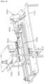
- FIG. 1 and FIG. 2 are schematic views of an automatic immunoassay system according to the present invention.
- the automatic immunoassay system includes a case 1000, a cartridge unit 2000, a light source unit 3000, a sensing unit 4000, a cartridge conveyance unit 5000, a tip 6000, a tip conveyance unit 7000, and a shutter unit 8000.
- the cartridge unit 2000, the light source unit 3000, the sensing unit 4000, the cartridge conveyance unit 5000, the tip 6000, the tip conveyance unit 7000, and the shutter unit 8000 are disposed to allow the automatic immunoassay system according to the present invention to be conveniently carried out by a user.
- the case 1000 may be formed at an upper portion thereof with a gripper and is provided therein with a holding plate 1100 to which the cartridge unit 2000, the light source unit 3000, the sensing unit 4000, the cartridge conveyance unit 5000, the tip 6000, the tip conveyance unit 7000, and the shutter unit 8000 are coupled.
- the holding plate 1100 may be disposed parallel to the ground and be separated a constant distance from a lower surface of the case 1000.
- the cartridge unit 2000 is disposed inside the case 1000 and is coupled to the holding plate 1100.
- the cartridge unit 2000 is formed with a plurality of wells, which contain a coating solution, an antibody-antigen reaction solution, a cleaning solution, and an enzyme-matrix reaction solution to perform photo-oxidation fluorescence amplification assay.
- the light source unit 3000 is disposed at one side of the cartridge unit 2000 to emit light to the wells.
- the cartridge conveyance unit 5000 is coupled to the cartridge unit 2000 and the holding plate 1100 to convey the cartridge unit 2000 on the holding plate 1100 in a horizontal direction.
- the well cartridge 2100 is provided with the plurality of wells in which the tip 6000 is sequentially dipped.
- the cartridge loading mechanism 2200 is coupled to a lower portion of the well cartridge 2100 to couple the well cartridge 2100 to the cartridge conveyance unit 5000.
- the light source unit 3000 includes a first light source 3100, a second light source 3200, and a light source unit mounting block 3300.
- the first light source 3100 is disposed at one side of the seventh well 2180 to emit light to the seventh well 2180 and the second light source 3200 is disposed at one side of the eighth well 2190 to emit light to the eighth well 2190.
- the light source unit mounting block 3300 is disposed at one side of the cartridge loading mechanism 2200 and the light source unit 3000 is mounted on the light source unit mounting block 3300.
- the sensing unit 4000 is disposed at the other side of the seventh well 2180 and the eighth well 2190 of the well cartridge 2100 to detect a fluorescence signal generated by light delivered to the wells.
- the sensing unit 4000 includes a first sensor 4100, a second sensor 4200, and a sensing unit mounting block 4300.
- the first sensor 4100 is disposed at the other side of the seventh well 2180 to detect a fluorescence signal generated by light delivered to the seventh well 2180
- the second sensor 4200 is disposed at the other side of the eighth well 2190 to detect a fluorescence signal generated by light delivered to the eighth well 2190.
- the automatic immunoassay system may include an assay unit (not shown), which analyzes the fluorescence signals detected by the sensing unit 4000.
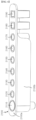
- FIG. 4 is a view of the well cartridge 2100 in the automatic immunoassay system according to the present invention.
- the well cartridge 2100 includes a tip storage well 2110, first to eighth wells 2120 to 2190, a well holder 2100a, and a well protecting portion 2100b.
- the tip storage well 2110 and the first to fourth wells 2120 to 2190 are formed in a tube shape such that the tip 6000 can be inserted thereinto, and are integrally formed with one another to be coupled to one another.
- the tip storage well 2110 defines a standby space for the tip 6000 before conveyance of the tip and receives the tip 6000 therein.
- the first to fourth wells 2120 to 2190 receive the coating solution and the antibody-antigen reaction solution such that the tip 6000 is sequentially received in the first to fourth wells 2120 to 2150 to form an antibody-antigen complex on the tip 6000.
- the seventh well 2180 and the eighth well 2190 receive the enzyme-matrix reaction solution such that the amount of an antigen coupled to an antibody can be measured through enzyme-matrix reaction of the tip 6000 therewith in these wells.
- the seventh well 2180 is a test target well and the eighth well 2190 is a reference well for comparison with the seventh well 2180.
- the tip storage well 2110 and the first to eighth wells 2120 to 2190 are sequentially disposed such that the tip 6000 can conveniently perform antibody-antigen immunoassay and can check fluorescence reaction while moving in the horizontal direction.
- the well holder 2100a is coupled to an outer periphery of an upper surface of each of the tip storage well 2110 and the first to eighth wells 2120 to 2190 such that the tip storage well 2110 is integrated with the first to eighth wells 2120 to 2190.
- FIG. 5 is a view of the cartridge loading mechanism 2200 in the automatic immunoassay system according to the present invention.
- the cartridge loading mechanism 2200 includes a well support 2210 and a well cover 2220.
- the well support 2210 is coupled at a lower portion thereof to the cartridge conveyance unit 5000 and is formed at an upper portion thereof with a plurality of well insertion holes 2211, into which lower portions of the first to eighth wells 2120 to 2190 are inserted.
- the well insertion holes 2211 are formed in a shape surrounding the lower portions of the first to eighth wells 2120 to 2190, respectively, such that the well support 2210 supports and secures the first to eighth wells 2120 to 2190 when the first to eighth wells 2120 to 2190 are inserted into the well insertion holes 2211.
- the well cover 2220 protrudes from an upper surface of the well support 2210 to surround the seventh well 2180 and the eighth well 2190 in the well support 2210.
- the well cover 2220 is formed at one side thereof with a first cover hole 2221 and a second cover hole 2222 such that one side of each of the seventh well 2180 and the eighth well 2190 is open through the corresponding cover hole.
- the well cover 2220 is formed at the other side thereof with a third cover hole 2223 and a fourth cover hole 2224 such that the other side of each of the seventh well 2180 and the eighth well 2190 is open through the corresponding cover hole.
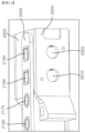
- FIG. 6 is a view of the light source unit mounting block 3300 in the automatic immunoassay system according to the present invention. Referring to FIG. 6 , the light source unit mounting block 3300 is coupled to one side of the well cover 2220.
- the light source unit mounting block 3300 is formed with a first light source coupling hole 3310 and a second light source coupling hole 3320 in regions thereof corresponding to the first cover hole 2221 and the second cover hole 2222.
- the first light source 3100 is inserted into and coupled to the first light source coupling hole 3310 and the second light source 3200 is inserted into and coupled to the second light source coupling hole 3320 such that the light source unit 3000 can emit light towards the seventh well 2180 and the eighth well 2190.
- FIG. 7 is a view of the sensing unit mounting block 4300 in the automatic immunoassay system according to the present invention.
- the sensing unit mounting block 4300 is coupled to the other side of the well cover 2220.
- the sensing unit mounting block 4300 includes a sensing unit-insertion block 4310 and a sensing printed circuit board 4320.
- the sensing unit-insertion block 4310 is coupled to the other side of the well cover 2220 and is formed with a first sensor coupling hole 4311 and a second sensor coupling hole 4312 in regions thereof corresponding to the third cover hole 2223 and the fourth cover hole 2224.
- the first sensor 4100 is inserted into and coupled to the first sensor coupling hole 4311 and the second sensor 4200 is inserted into and coupled to the second sensor coupling hole 4312 such that the sensing unit 4000 can detect a fluorescence signal generated by light delivered to the seventh well 2180 and the eighth well 2190.
- the sensing printed circuit board 4320 is coupled to the sensing unit-insertion block 4310 to be connected to the first sensor 4100 and the second sensor 4200 such that the fluorescence signal detected by the sensing unit 4000 can be sent to and analyzed by the assay unit.
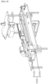
- FIG. 8 is a view of the cartridge conveyance unit 5000 in the automatic immunoassay system according to the present invention.
- the cartridge conveyance unit 5000 includes a cartridge mount 5100 and a cartridge conveyer 5200.
- the cartridge conveyance unit 5000 couples the cartridge unit 2000 to the holding plate 1100 such that the cartridge unit 2000 can be conveyed thereon.
- the cartridge conveyer 5200 conveys the cartridge mount 5100 in the horizontal direction with reference to the holding plate 1100.
- FIG. 9 is a view of the cartridge mount 5100 in the automatic immunoassay system according to the present invention.
- the cartridge mount 5100 includes a first guide bar holding frame 5110, a second guide bar holding frame 5120, a conveyance guide bar 5130, a conveyance frame 5140, and a cartridge mounting plate 5150.
- the first guide bar holding frame 5110 and the second guide bar holding frame 5120 are coupled to opposite ends of the holding plate 1100 with reference to a longitudinal direction of the holding plate 1100, that is, in a direction in which the cartridge unit 2000 is conveyed, respectively.
- the conveyance guide bar 5130 is coupled at opposite ends thereof to the first guide bar holding frame 5110 and the second guide bar holding frame 5120, respectively.
- the conveyance guide bar 5130 may be composed of a single guide bar, the conveyance guide bar is preferably composed of two or more guide bars disposed at both sides of the cartridge unit 2000.
- the conveyance frame 5140 is formed with a guide bar passing hole 5141, through which the conveyance guide bar 5130 passes. Accordingly, as the conveyance guide bar 5130 is inserted into the guide bar passing hole 5141, the conveyance frame 5140 is coupled to the conveyance guide bar 5130 to be moved in the horizontal direction with reference to the conveyance guide bar 5130.
- the cartridge mounting plate 5150 is coupled to an upper portion of the conveyance frame 5140. Accordingly, as the conveyance frame 5140 is conveyed in the horizontal direction with reference to the conveyance guide bar 5130, the cartridge mounting plate 5150 is also conveyed together with the conveyance frame 5140 in the same direction.
- the cartridge unit 2000, the light source unit 3000 and the sensing unit 4000 are coupled to an upper surface of the cartridge mounting plate 5150. Accordingly, as the cartridge mounting plate 5150 is conveyed in the horizontal direction, the cartridge unit 2000, the light source unit 3000 and the sensing unit 4000 are also conveyed in the same direction at the same speed as the cartridge mounting plate 5150.
- FIG. 10 is a view of the cartridge conveyer 5200 in the automatic immunoassay system according to the present invention.
- the cartridge conveyer is coupled to the cartridge mount 5100 to convey the cartridge mount 5100 in the horizontal direction.
- the cartridge conveyer 5200 includes a stepper motor 5210, a rotary block, a timing belt 5230, and a conveyance block 5240.
- the stepper motor 5210 serves to provide drive power for driving the rotary block described below. Referring to FIG. 10 , the stepper motor 5210 is disposed under the holding plate 1100, thereby enabling a compact design of the automatic immunoassay system according to the present invention.
- the rotary block includes a first rotary block 5221 and a second rotary block 5222.
- the first rotary block 5221 and the second rotary block 5222 are coupled to the upper surface of the holding plate 1100, in which the first rotary block 5221 is separated from a side surface of the first guide bar holding frame 5110 and the second rotary block 5222 is separated from a side surface of the second guide bar holding frame 5120.
- each of the first rotary block 5221 and the second rotary block 5222 has a cylindrical shape and is formed in a perpendicular direction with respect to the upper surface of the holding plate 1100.
- the stepper motor 5210 is coupled to the first rotary block 5221 to rotate the first rotary block 5221 in the clockwise direction or in the counterclockwise direction.
- the timing belt 5230 is coupled to outer surfaces of the first rotary block 5221 and the second rotary block 5222 to cooperate therewith. Accordingly, when the stepper motor 5210 is driven, the first rotary block 5221 is rotated to allow the timing belt 5230 engaging with the first rotary block 5221 to be rotated together therewith, and the second rotary block 5222 is also rotated by rotation of the timing belt 5230.
- the second rotary block 5222 assists in rotation of the timing belt 5230 while maintaining tension of the timing belt 5230.
- the outer surfaces of the first rotary block 5221 and the second rotary block 5222 are formed with the same shape of roughness as an inner surface of the timing belt 5230, which engages with the outer surfaces of the first rotary block 5221 and the second rotary block 5222 to allow more efficient transfer of rotating force.
- the conveyance block 5240 is coupled to the timing belt to be conveyed on the timing belt 5230 by rotation of the timing belt 5230.
- the conveyance frame 5140 is rotated together with the timing belt 5230, thereby allowing conveyance of the cartridge unit 2000 in the horizontal direction.
- FIG. 11 is a view of the tip conveyance unit 7000 in the automatic immunoassay system according to the present invention.
- the tip conveyance unit 7000 includes a tip holder 7100, a tip conveyance unit 7200, and a tip vibrator 7300.
- the tip holder 7100 is coupled to an upper surface of the holding plate 1100 and to the tip 6000.
- the tip conveyance unit 7200 conveys the tip 6000 to be dipped in the plurality of wells.
Landscapes
- Health & Medical Sciences (AREA)
- Immunology (AREA)
- Life Sciences & Earth Sciences (AREA)
- Chemical & Material Sciences (AREA)
- Physics & Mathematics (AREA)
- Pathology (AREA)
- Analytical Chemistry (AREA)
- Biochemistry (AREA)
- General Health & Medical Sciences (AREA)
- General Physics & Mathematics (AREA)
- Engineering & Computer Science (AREA)
- Molecular Biology (AREA)
- Biomedical Technology (AREA)
- Hematology (AREA)
- Urology & Nephrology (AREA)
- Food Science & Technology (AREA)
- Medicinal Chemistry (AREA)
- Biotechnology (AREA)
- Microbiology (AREA)
- Chemical Kinetics & Catalysis (AREA)
- Cell Biology (AREA)
- Nuclear Medicine, Radiotherapy & Molecular Imaging (AREA)
- Optics & Photonics (AREA)
- Automatic Analysis And Handling Materials Therefor (AREA)
- Investigating, Analyzing Materials By Fluorescence Or Luminescence (AREA)
- Bioinformatics & Cheminformatics (AREA)
- Bioinformatics & Computational Biology (AREA)
- Biophysics (AREA)
- Proteomics, Peptides & Aminoacids (AREA)
- Peptides Or Proteins (AREA)
Description
- The present invention relates to an automatic immunoassay system, and more particularly to an automatic immunoassay system capable of performing photo-oxidation fluorescence amplification assay with greater convenience through automatic movement of a tip to a plurality of wells containing solutions performing different roles, respectively.
- In recent years, with the completion of the human genome project and the advent of the postgenomic era, it becomes difficult to rapidly treat large amounts of micro-data pouring out of existing laboratory assay systems.
- Accordingly, implementation of a micro-comprehensive assay system or lab-on-a-chip to perform rapid assay on rapidly increasing micro-data can be effectively achieved through combination with suitable bioassay methods.
- Methods for assay of biomolecules include immunoassays, DNA hybridization, receptor-based assay, and the like. A detection method for assay of the biomolecules is broadly used not only in laboratory assay, but also in medical diagnosis or development of new medicines.
- Among these methods, enzyme-linked immunosorbent assay (ELISA) is an experimental method that confirms an antigen-antibody reaction through an enzyme bound to an antibody, and is mainly used to perform qualitative and quantitative assay of the antibody or antigen. The enzyme-linked immunosorbent assay is a simple and accurate test method and can analyze many samples at once.
- However, there are problems in that, in order to perform a process of attaching samples, antibodies and antigens to a tip, a cleaning process, and a sensing process in wells each containing a corresponding solution, it is necessary to provide individual wells for the corresponding purposes and to dip a tip in the wells and the time for experiment is increased due to a process of moving the tip to the wells having different roles.
- Moreover, since a well having completed reaction must be moved to a separate assay system, there are problems of a complicated experiment process and deformation of an assay target specimen in the course of moving the well.
-
Korean Patent Registration No. 10-1809645 (Title of the Invention: Automatic immunoassay system, Issue Date: December 15, 2017 -
JP 2008-014636 A EP 2 154 513 A1 relates to a photometric apparatus and an automatic analyzer in which liquid samples contained in vessels are measured with light of different wavelengths while the vessels are transferred are provided. -
US 5,324,635 relates to an analyzer having a reaction disk for holding a plurality of reaction containers and a fluorophotometer for measuring fluorescence stemming from solutions in the containers. -
US 2021/0311033 A1 relates to an ELISA-based, liquid-phase immunoassay apparatus optimized for detecting particular ingredients contained in a biological sample, etc., and a method therefor. -
US 2021/0270819 A1 relates to a device for carrying out heterogeneous immunoassays by means of magnetic particles in cuvettes lined up next to one another, wherein each cuvette has a filling opening and at least one lateral measurement window which is transparent to the measurement radiation. -
US 2021/0041472 A1 relates to a method and/or a device for carrying out chemical, biochemical and/or immunochemical analyses of liquid samples, which are present in a sample store of an automatic analyzer, with the aid of liquid reagents which are present in at least one reagent store of the analyzer. - Embodiments of the present invention are conceived to solve such problems in the art and it is an object of the present invention to provide an automatic immunoassay system capable of performing photo-oxidation fluorescence amplification assay with greater convenience through automatic movement of a tip to a plurality of wells containing solutions performing different roles, respectively.
- It will be understood that objects of the present invention are not limited to the above. The above and other objects of the present invention will become apparent to those skilled in the art from the detailed description of the following embodiments in conjunction with the accompanying drawings.
- The above objects are achieved by the features defined in independent claim 1. Further preferred features are specified in the dependent claims.
- In accordance with one aspect of the present invention, an automatic immunoassay system includes: a case provided with a holding plate therein; a cartridge unit disposed inside the case to be coupled to the holding plate and formed with a plurality of wells; a light source unit disposed at one side of the cartridge unit to emit light to the wells; a sensing unit disposed at the other side of the cartridge unit to detect a fluorescence signal generated by light delivered to the wells; a cartridge conveyance unit coupled to the cartridge unit and the holding plate and moving the cartridge unit on the holding plate in a horizontal direction; a tip disposed above the cartridge unit to be sequentially dipped in the plurality of wells; and a tip conveyance unit coupled to an upper surface of the holding plate and moving the tip in an upward/downward direction. The system further comprises: a shutter unit (8000) disposed between the light source unit (3000) and the wells to block light emitted from the light source unit (3000) to the wells or allow the light emitted from the light source unit (3000) to reach the wells, wherein the shutter unit (8000) comprises: a shutter body (8200) disposed between the light source unit (3000) and the wells to block light emitted from the light source unit (3000) from being delivered to the wells; and a shutter pushing portion (8100) coupled to an upper portion of the holding plate (1100) to move the shutter body (8200).
- The cartridge unit may include: a well cartridge provided with the plurality of wells; and a cartridge loading mechanism coupled to a lower portion of the well cartridge to couple the well cartridge to the holding plate.
- The cartridge conveyance unit may include: a cartridge mount coupling the cartridge unit to the holding plate; and a cartridge conveyer conveying the cartridge mount in a horizontal direction with reference to the holding plate.
- The tip conveyance unit may include: a tip holder holding the tip; and a tip conveyer conveying the tip holder in the upward/downward direction.
- The automatic immunoassay system according to the present invention provides the following effects.
- First, the automatic immunoassay system enables photo-oxidation fluorescence amplification assay with greater convenience through automatic movement of a tip to a plurality of wells containing solutions performing different roles.
- Second, in the automatic immunoassay system, the plurality of wells containing solutions performing different roles is disposed in a single cartridge, and the light source unit is integrally formed with the sensing unit, thereby enabling photo-oxidation fluorescence amplification assay with greater convenience.
- Thirdly, the automatic immunoassay system includes a shutter unit disposed between the light source unit and the wells to block light emitted from the light source unit to the wells or to allow the light emitted from the light source unit to reach the wells, thereby enabling more accurate assay through irradiation of the well with the light emitted from the light source unit after completion of warm-up of the light source unit so as to allow irradiation of a sample with uniform light when there is a need for warm-up of the light source unit.
- It will be understood that advantageous effects of the present invention are not limited to the above and include any advantageous effects conceivable from the features disclosed in the detailed description of the invention or the appended claims.
- The above and other aspects, features, and advantages of the present invention will become apparent from the detailed description of the following embodiments in conjunction with the accompanying drawings:
-
FIG. 1 andFIG. 2 are schematic views of an automatic immunoassay system according to the present invention; -
FIG. 3 is a view of a cartridge unit, a light source unit and a sensing unit in the automatic immunoassay system according to the present invention; -
FIG. 4 is a view of a well cartridge in the automatic immunoassay system according to the present invention; -
FIG. 5 is a view of a cartridge loading mechanism in the automatic immunoassay system according to the present invention; -
FIG. 6 is a view of a light source unit mounting block in the automatic immunoassay system according to the present invention; -
FIG. 7 is a view of a sensing unit mounting block in the automatic immunoassay system according to the present invention; -
FIG. 8 is a view of a cartridge conveyance unit in the automatic immunoassay system according to the present invention; -
FIG. 9 is a view of a cartridge mount in the automatic immunoassay system according to the present invention; -
FIG. 10 is a view of a cartridge conveyer in the automatic immunoassay system according to the present invention; -
FIG. 11 is a view of a tip conveyance unit in the automatic immunoassay system according to the present invention; and -
FIG. 12 is a view of a shutter unit in the automatic immunoassay system according to the present invention. - Hereinafter, exemplary embodiments of the invention will be described in detail with reference to the accompanying drawings. It should be understood that the present invention is not limited to the following embodiments and may be embodied in different ways, and that the embodiments are given to provide complete disclosure of the invention and to provide thorough understanding of the invention to those skilled in the art. The scope of the invention is limited only by the accompanying claims. Like components will be denoted by like reference numerals throughout the specification.
- The terminology used herein is for the purpose of describing particular embodiments and is not intended to be limiting. As used herein, the singular forms, "a," "an," and "the" are intended to include the plural forms as well, unless the context clearly indicates otherwise. Moreover, the terms "comprises," "comprising," "includes," and/or "including," when used in this specification, specify the presence of stated features, integers, steps, operations, elements, components, and/or groups thereof, but do not preclude the presence or addition of one or more other features, integers, steps, operations, elements, components, and/or groups thereof.
- It will be understood that when an element is referred to as being "connected" to or "on" another element, it can be directly on the other element, or intervening elements may also be present. In contrast, when an element is referred to as being "directly connected" to or "directly on" another element, there are no intervening elements present. Other expressions for describing a relationship between components should be interpreted in the same way as above.
- Unless otherwise defined herein, all terms including technical or scientific terms used herein have the same meanings as commonly understood by those skilled in the art to which the present invention belongs. It will be further understood that terms, such as those defined in commonly used dictionaries, should be interpreted as having a meaning that is consistent with their meaning in the context of the specification and relevant art and should not be interpreted in an idealized or overly formal sense unless expressly so defined herein.
-
FIG. 1 andFIG. 2 are schematic views of an automatic immunoassay system according to the present invention. - Referring to
FIG. 1 andFIG. 2 , the automatic immunoassay system according to the present invention includes acase 1000, acartridge unit 2000, alight source unit 3000, asensing unit 4000, acartridge conveyance unit 5000, atip 6000, atip conveyance unit 7000, and ashutter unit 8000. - In the
case 1000, thecartridge unit 2000, thelight source unit 3000, thesensing unit 4000, thecartridge conveyance unit 5000, thetip 6000, thetip conveyance unit 7000, and theshutter unit 8000 are disposed to allow the automatic immunoassay system according to the present invention to be conveniently carried out by a user. - The
case 1000 may be formed at an upper portion thereof with a gripper and is provided therein with aholding plate 1100 to which thecartridge unit 2000, thelight source unit 3000, thesensing unit 4000, thecartridge conveyance unit 5000, thetip 6000, thetip conveyance unit 7000, and theshutter unit 8000 are coupled. - The holding
plate 1100 may be disposed parallel to the ground and be separated a constant distance from a lower surface of thecase 1000. - The
cartridge unit 2000 is disposed inside thecase 1000 and is coupled to theholding plate 1100. Thecartridge unit 2000 is formed with a plurality of wells, which contain a coating solution, an antibody-antigen reaction solution, a cleaning solution, and an enzyme-matrix reaction solution to perform photo-oxidation fluorescence amplification assay. - The
light source unit 3000 is disposed at one side of thecartridge unit 2000 to emit light to the wells. - The
sensing unit 4000 is disposed at the other side of thecartridge unit 2000 to face thelight source unit 3000 and senses a fluorescence signal generated by light delivered to the wells. - The
cartridge conveyance unit 5000 is coupled to thecartridge unit 2000 and theholding plate 1100 to convey thecartridge unit 2000 on theholding plate 1100 in a horizontal direction. - The
tip 6000 is disposed above thecartridge unit 2000 to be sequentially dipped in the plurality of wells. - The
tip conveyance unit 7000 is coupled to an upper surface of the holdingplate 1100 to convey thetip 6000 in an upward/downward direction. - The
shutter unit 8000 is disposed and moved between thelight source unit 3000 and the wells to block light emitted from thelight source unit 3000 to the wells or to allow the light emitted from thelight source unit 3000 to reach the wells. - Details of the
cartridge unit 2000, thelight source unit 3000, thesensing unit 4000, thecartridge conveyance unit 5000, thetip 6000, thetip conveyance unit 7000, and theshutter unit 8000 will be described with reference toFIG. 3 to FIG. 12 . - Referring to
FIG. 3 to FIG. 8 , thecartridge unit 2000 of the automatic immunoassay system according to the present invention will be described hereinafter. -
FIG. 3 is a view of thecartridge unit 2000, thelight source unit 3000 and thesensing unit 4000 in the automatic immunoassay system according to the present invention. Referring toFIG. 3 , thecartridge unit 2000 includes awell cartridge 2100 and acartridge loading mechanism 2200. - The
well cartridge 2100 is provided with the plurality of wells in which thetip 6000 is sequentially dipped. - The
cartridge loading mechanism 2200 is coupled to a lower portion of thewell cartridge 2100 to couple thewell cartridge 2100 to thecartridge conveyance unit 5000. - The
light source unit 3000 is disposed at one side of aseventh well 2180 and aneighth well 2190 in thewell cartridge 2100 to emit light to the wells. - The
light source unit 3000 includes afirst light source 3100, a secondlight source 3200, and a light sourceunit mounting block 3300. - The
first light source 3100 is disposed at one side of the seventh well 2180 to emit light to theseventh well 2180 and the secondlight source 3200 is disposed at one side of the eighth well 2190 to emit light to theeighth well 2190. - The light source
unit mounting block 3300 is disposed at one side of thecartridge loading mechanism 2200 and thelight source unit 3000 is mounted on the light sourceunit mounting block 3300. - The
sensing unit 4000 is disposed at the other side of theseventh well 2180 and the eighth well 2190 of thewell cartridge 2100 to detect a fluorescence signal generated by light delivered to the wells. - The
sensing unit 4000 includes afirst sensor 4100, asecond sensor 4200, and a sensingunit mounting block 4300. - The
first sensor 4100 is disposed at the other side of the seventh well 2180 to detect a fluorescence signal generated by light delivered to theseventh well 2180, and thesecond sensor 4200 is disposed at the other side of the eighth well 2190 to detect a fluorescence signal generated by light delivered to theeighth well 2190. - In addition, the automatic immunoassay system according to the present invention may include an assay unit (not shown), which analyzes the fluorescence signals detected by the
sensing unit 4000. -
FIG. 4 is a view of thewell cartridge 2100 in the automatic immunoassay system according to the present invention. Referring toFIG. 4 , thewell cartridge 2100 includes atip storage well 2110, first toeighth wells 2120 to 2190, awell holder 2100a, and a well protectingportion 2100b. - The
tip storage well 2110 and the first tofourth wells 2120 to 2190 are formed in a tube shape such that thetip 6000 can be inserted thereinto, and are integrally formed with one another to be coupled to one another. - The
tip storage well 2110 defines a standby space for thetip 6000 before conveyance of the tip and receives thetip 6000 therein. - The first to
fourth wells 2120 to 2190 receive the coating solution and the antibody-antigen reaction solution such that thetip 6000 is sequentially received in the first tofourth wells 2120 to 2150 to form an antibody-antigen complex on thetip 6000. - The
fifth well 2160 and thesixth well 2170 receive the cleaning solution such that the tip formed with the antibody-antigen complex is subjected to cleaning in two stages to remove an antibody not forming the antibody-antigen complex, after thetip 6000 is sequentially received in the first tofourth wells 2120 to 2150. - The
seventh well 2180 and the eighth well 2190 receive the enzyme-matrix reaction solution such that the amount of an antigen coupled to an antibody can be measured through enzyme-matrix reaction of thetip 6000 therewith in these wells. - Here, the
seventh well 2180 is a test target well and theeighth well 2190 is a reference well for comparison with theseventh well 2180. - The
tip storage well 2110 and the first toeighth wells 2120 to 2190 are sequentially disposed such that thetip 6000 can conveniently perform antibody-antigen immunoassay and can check fluorescence reaction while moving in the horizontal direction. - The
well holder 2100a is coupled to an outer periphery of an upper surface of each of thetip storage well 2110 and the first toeighth wells 2120 to 2190 such that thetip storage well 2110 is integrated with the first toeighth wells 2120 to 2190. - The well protecting
portion 2100b protrudes from a lower portion of thewell holder 2100a, particularly from lower regions of thewell holder 2100a corresponding to thetip storage well 2110 and the first toeighth wells 2120 to 2170, to protect thetip storage well 2110 and the first toeighth wells 2120 to 2170 from external light and the like. -
FIG. 5 is a view of thecartridge loading mechanism 2200 in the automatic immunoassay system according to the present invention. Referring toFIG. 5 , thecartridge loading mechanism 2200 includes awell support 2210 and awell cover 2220. - The
well support 2210 is coupled at a lower portion thereof to thecartridge conveyance unit 5000 and is formed at an upper portion thereof with a plurality ofwell insertion holes 2211, into which lower portions of the first toeighth wells 2120 to 2190 are inserted. - The
well insertion holes 2211 are formed in a shape surrounding the lower portions of the first toeighth wells 2120 to 2190, respectively, such that thewell support 2210 supports and secures the first toeighth wells 2120 to 2190 when the first toeighth wells 2120 to 2190 are inserted into the well insertion holes 2211. - The
well cover 2220 protrudes from an upper surface of thewell support 2210 to surround theseventh well 2180 and the eighth well 2190 in thewell support 2210. - Here, the
well cover 2220 is formed at one side thereof with afirst cover hole 2221 and asecond cover hole 2222 such that one side of each of theseventh well 2180 and theeighth well 2190 is open through the corresponding cover hole. - The
well cover 2220 is formed at the other side thereof with athird cover hole 2223 and afourth cover hole 2224 such that the other side of each of theseventh well 2180 and theeighth well 2190 is open through the corresponding cover hole. -
FIG. 6 is a view of the light sourceunit mounting block 3300 in the automatic immunoassay system according to the present invention. Referring toFIG. 6 , the light sourceunit mounting block 3300 is coupled to one side of thewell cover 2220. - The light source
unit mounting block 3300 is formed with a first lightsource coupling hole 3310 and a second lightsource coupling hole 3320 in regions thereof corresponding to thefirst cover hole 2221 and thesecond cover hole 2222. - The
first light source 3100 is inserted into and coupled to the first lightsource coupling hole 3310 and the secondlight source 3200 is inserted into and coupled to the second lightsource coupling hole 3320 such that thelight source unit 3000 can emit light towards theseventh well 2180 and theeighth well 2190. -
FIG. 7 is a view of the sensingunit mounting block 4300 in the automatic immunoassay system according to the present invention. Referring toFIG. 7 , the sensingunit mounting block 4300 is coupled to the other side of thewell cover 2220. Specifically, the sensingunit mounting block 4300 includes a sensing unit-insertion block 4310 and a sensing printedcircuit board 4320. - The sensing unit-
insertion block 4310 is coupled to the other side of thewell cover 2220 and is formed with a firstsensor coupling hole 4311 and a secondsensor coupling hole 4312 in regions thereof corresponding to thethird cover hole 2223 and thefourth cover hole 2224. - The
first sensor 4100 is inserted into and coupled to the firstsensor coupling hole 4311 and thesecond sensor 4200 is inserted into and coupled to the secondsensor coupling hole 4312 such that thesensing unit 4000 can detect a fluorescence signal generated by light delivered to theseventh well 2180 and theeighth well 2190. - The sensing printed
circuit board 4320 is coupled to the sensing unit-insertion block 4310 to be connected to thefirst sensor 4100 and thesecond sensor 4200 such that the fluorescence signal detected by thesensing unit 4000 can be sent to and analyzed by the assay unit. -
FIG. 8 is a view of thecartridge conveyance unit 5000 in the automatic immunoassay system according to the present invention. Referring toFIG. 8 , thecartridge conveyance unit 5000 includes acartridge mount 5100 and acartridge conveyer 5200. - The
cartridge conveyance unit 5000 couples thecartridge unit 2000 to theholding plate 1100 such that thecartridge unit 2000 can be conveyed thereon. - The
cartridge conveyer 5200 conveys thecartridge mount 5100 in the horizontal direction with reference to theholding plate 1100. -
FIG. 9 is a view of thecartridge mount 5100 in the automatic immunoassay system according to the present invention. Referring toFIG. 9 , thecartridge mount 5100 includes a first guidebar holding frame 5110, a second guidebar holding frame 5120, aconveyance guide bar 5130, aconveyance frame 5140, and acartridge mounting plate 5150. - The first guide
bar holding frame 5110 and the second guidebar holding frame 5120 are coupled to opposite ends of the holdingplate 1100 with reference to a longitudinal direction of the holdingplate 1100, that is, in a direction in which thecartridge unit 2000 is conveyed, respectively. - The
conveyance guide bar 5130 is coupled at opposite ends thereof to the first guidebar holding frame 5110 and the second guidebar holding frame 5120, respectively. Although theconveyance guide bar 5130 may be composed of a single guide bar, the conveyance guide bar is preferably composed of two or more guide bars disposed at both sides of thecartridge unit 2000. - The
conveyance frame 5140 is formed with a guidebar passing hole 5141, through which theconveyance guide bar 5130 passes. Accordingly, as theconveyance guide bar 5130 is inserted into the guidebar passing hole 5141, theconveyance frame 5140 is coupled to theconveyance guide bar 5130 to be moved in the horizontal direction with reference to theconveyance guide bar 5130. - The
cartridge mounting plate 5150 is coupled to an upper portion of theconveyance frame 5140. Accordingly, as theconveyance frame 5140 is conveyed in the horizontal direction with reference to theconveyance guide bar 5130, thecartridge mounting plate 5150 is also conveyed together with theconveyance frame 5140 in the same direction. - In addition, the
cartridge unit 2000, thelight source unit 3000 and thesensing unit 4000 are coupled to an upper surface of thecartridge mounting plate 5150. Accordingly, as thecartridge mounting plate 5150 is conveyed in the horizontal direction, thecartridge unit 2000, thelight source unit 3000 and thesensing unit 4000 are also conveyed in the same direction at the same speed as thecartridge mounting plate 5150. -
FIG. 10 is a view of thecartridge conveyer 5200 in the automatic immunoassay system according to the present invention. Referring toFIG. 10 , the cartridge conveyer is coupled to thecartridge mount 5100 to convey thecartridge mount 5100 in the horizontal direction. Specifically, thecartridge conveyer 5200 includes astepper motor 5210, a rotary block, atiming belt 5230, and aconveyance block 5240. - The
stepper motor 5210 serves to provide drive power for driving the rotary block described below. Referring toFIG. 10 , thestepper motor 5210 is disposed under the holdingplate 1100, thereby enabling a compact design of the automatic immunoassay system according to the present invention. - The rotary block includes a
first rotary block 5221 and asecond rotary block 5222. Thefirst rotary block 5221 and thesecond rotary block 5222 are coupled to the upper surface of the holdingplate 1100, in which thefirst rotary block 5221 is separated from a side surface of the first guidebar holding frame 5110 and thesecond rotary block 5222 is separated from a side surface of the second guidebar holding frame 5120. - Preferably, each of the
first rotary block 5221 and thesecond rotary block 5222 has a cylindrical shape and is formed in a perpendicular direction with respect to the upper surface of the holdingplate 1100. - The
stepper motor 5210 is coupled to thefirst rotary block 5221 to rotate thefirst rotary block 5221 in the clockwise direction or in the counterclockwise direction. - The
timing belt 5230 is coupled to outer surfaces of thefirst rotary block 5221 and thesecond rotary block 5222 to cooperate therewith. Accordingly, when thestepper motor 5210 is driven, thefirst rotary block 5221 is rotated to allow thetiming belt 5230 engaging with thefirst rotary block 5221 to be rotated together therewith, and thesecond rotary block 5222 is also rotated by rotation of thetiming belt 5230. - That is, the
second rotary block 5222 assists in rotation of thetiming belt 5230 while maintaining tension of thetiming belt 5230. - The outer surfaces of the
first rotary block 5221 and thesecond rotary block 5222 are formed with the same shape of roughness as an inner surface of thetiming belt 5230, which engages with the outer surfaces of thefirst rotary block 5221 and thesecond rotary block 5222 to allow more efficient transfer of rotating force. - The
conveyance block 5240 is coupled to the timing belt to be conveyed on thetiming belt 5230 by rotation of thetiming belt 5230. In addition, as theconveyance block 5240 is conveyed in the same direction as thetiming belt 5230 upon rotation of thetiming belt 5230 secured to theconveyance frame 5140, theconveyance frame 5140 is rotated together with thetiming belt 5230, thereby allowing conveyance of thecartridge unit 2000 in the horizontal direction. -
FIG. 11 is a view of thetip conveyance unit 7000 in the automatic immunoassay system according to the present invention. Referring toFIG. 11 , thetip conveyance unit 7000 includes atip holder 7100, atip conveyance unit 7200, and atip vibrator 7300. - The
tip holder 7100 is coupled to an upper surface of the holdingplate 1100 and to thetip 6000. - As the
tip holder 7100 is conveyed in the upward/downward direction, thetip conveyance unit 7200 conveys thetip 6000 to be dipped in the plurality of wells. - The
tip vibrator 7300 is coupled to thetip holder 7100 to allow more efficient culturing, cleaning and reaction by vibrating the tip when thetip 6000 is dipped in the well. -
FIG. 12 is a view of theshutter unit 8000 in the automatic immunoassay system according to the present invention. Referring toFIG. 12 , theshutter unit 8000 includes ashutter pushing portion 8100 and ashutter body 8200. - The
shutter pushing portion 8100 is coupled to an upper surface of the holdingplate 1100 to move theshutter body 8200. Specifically, theshutter pushing portion 8100 includes apush lever base 8110 and apush lever 8120. - The
push lever base 8110 is coupled to the upper surface the holdingplate 1100 so as to face theeighth well 2190. - The
push lever 8120 is coupled to one end of thepush lever base 8110 and extends towards theshutter body 8200. When thecartridge conveyance unit 5000 conveys thecartridge unit 2000 from thefirst well 2120 towards theeighth well 2190, thepush lever 8120 pushes theshutter body 8200 to move theshutter body 8200 towards theeighth well 2190. - The
shutter body 8200 is disposed between thelight source unit 3000 and the well to block light emitted from thelight source unit 3000 towards the wells or to allow the light emitted from thelight source unit 3000 to reach the wells depending upon locations of the wells. - Specifically, the
shutter body 8200 includes abase block 8210, ashutter link 8220, ashutter jig 8230, and ashutter plate 8240. - The
base block 8210 is coupled to an upper portion of thecartridge mounting plate 5150 to be disposed near theeighth well 2190. - The
shutter link 8220 is rotatably coupled at one end thereof to the base block and theshutter jig 8230 is rotatably coupled to the other end of theshutter link 8220. - That is, as the
cartridge conveyance unit 5000 conveys thecartridge conveyance unit 5000 in a direction from the first well 2120 to theeighth well 2190, thepush lever 8120 pushes theshutter jig 8230 towards theeighth well 2190. As a result, theshutter link 8220 is rotated to move theshutter jig 8230 in a direction from the eighth well 2190 to thefirst well 2120. - The
shutter plate 8240 is rotatably coupled to one end of theshutter jig 8230 to be disposed between thelight source unit 3000 and the well and is formed with light emission holes 8241. - In an Off state in which the
push lever 8120 does not push theshutter jig 8230, theshutter plate 8240 blocks light emitted from thelight source unit 3000 from being delivered to theseventh well 2180 and theeighth well 2190. - Then, after the
tip 6000 is sequentially dipped in the first toeighth wells 2120 to 2190 to complete reaction, thelight source unit 3000 emits light to theseventh well 2180 and theeighth well 2190. In this course, in an On state in which thepush lever 8120 pushes theshutter jig 8230 to move theshutter plate 8240, thelight emission holes 8241 formed through theshutter plate 8240 are disposed between thelight source unit 3000 and the seventh andeighth wells light source unit 3000 can be delivered to theseventh well 2180 and theeighth well 2190. - Here, when the
push lever 8120 pushes theshutter jig 8230 to move theshutter plate 8240, theshutter plate 8240 is moved while being kept parallel to thecartridge mounting plate 5150 such that thelight emission holes 8241 of theshutter plate 8240 are arranged between theseventh well 2180 and theeighth well 2190. - To this end, the light source
unit mounting block 3300 is formed with a shutterplate moving groove 3331 on a surface thereof facing theshutter plate 8240 such that theshutter plate 8240 can be inserted into the light sourceunit mounting block 3300 therethrough and can be moved while being kept parallel to thecartridge mounting plate 5150. - As a result, with the
shutter unit 8000 adapted to block the light emitted from thelight source unit 3000 from being delivered to theseventh well 2180 and the eighth well 2190 or to allow the light emitted from thelight source unit 3000 to be delivered thereto, the automatic immunoassay system can perform more accurate assay of a sample by allowing the light emitted from thelight source unit 3000 to be delivered to the wells after completion of warm-up of thelight source unit 3000 such that the sample can be evenly irradiated with the light, when there is a need for warm-up of thelight source unit 3000. - Although some embodiments have been described herein with reference to the accompanying drawings, it should be understood that these embodiments are provided for illustration only and are not to be construed in any way as limiting the present invention.
-
1000: Case 1100: Holding plate 2000: Cartridge unit 2100: Well cartridge 2110: Tip storage well 2120: First well 2130: Second well 2140: Third well 2150: Fourth well 2160: Fifth well 2170: Sixth well 2180: Seventh well 2190: Eighth well 2100a: Well holder 2100b: Well protecting portion 2200: Cartridge loading mechanism 2210: Well support 2211: Well insertion hole 2220: Well cover 2221: First cover hole 2222: Second cover hole 2223: Third cover hole 2224: Fourth cover hole 3000: Light source unit 3100: First light source 3200: Second light source 3300: Light source unit mounting block 3310: First light source coupling hole 3320: Second light source coupling hole 3331: Shutter plate moving groove 4000: Sensing unit 4100: First sensor 4200: Second sensor 4300: Sensing unit mounting block 4310: Sensing unit-insertion block 4311: First sensor coupling hole 4312: Second sensor coupling hole 4320: Sensing printed circuit board 5000: Cartridge conveyance unit 5100: Cartridge mount 5110: First guide bar holding frame 5120: Second guide bar holding frame 5130: Conveyance guide bar 5140: Conveyance frame 5141: Guide bar passing hole 5150: Cartridge mounting plate 5200: Cartridge conveyer 5210: Stepper motor 5221: First rotary block 5222: Second rotary block 5230: Timing belt 5240: Conveyance block 6000: Tip 7000: Tip conveyance unit 7100: Tip holder 7200: Tip conveyance unit 7300: Tip vibrator 8000: Shutter unit 8100: Shutter pushing portion 8110: Push lever base 8120: Push lever 8200: Shutter body 8210: Base block 8220: Shutter link 8230: Shutter jig 8240: Shutter plate
Claims (4)
- An automatic immunoassay system comprising:a case (1000) provided with a holding plate (1100) therein;a cartridge unit (2000) disposed inside the case (1000), being coupled to the holding plate (1100) and formed with a plurality of wells;a light source unit (3000) disposed at one side of the cartridge unit (2000) to emit light to the wells;a sensing unit (4000) disposed at the other side of the cartridge unit (2000) to detect a fluorescence signal generated by light delivered to the wells;a cartridge conveyance unit (5000) coupled to the cartridge unit (2000) and the holding plate (1100) and moving the cartridge unit (2000) on the holding plate (1100) in a horizontal direction;a tip (6000) disposed above the cartridge unit (2000) to be sequentially dipped in the plurality of wells; anda tip conveyance unit (7000) coupled to an upper surface of the holding plate (1100) and moving the tip (6000) in an upward/downward direction,characterized in that the system further comprises:a shutter unit (8000) disposed between the light source unit (3000) and the wells to block light emitted from the light source unit (3000) to the wells or allow the light emitted from the light source unit (3000) to reach the wells,wherein the shutter unit (8000) comprises:a shutter body (8200) disposed between the light source unit (3000) and the wells to block light emitted from the light source unit (3000) from being delivered to the wells; anda shutter pushing portion (8100) coupled to an upper portion of the holding plate (1100) to move the shutter body (8200).
- The automatic immunoassay system according to claim 1, wherein the cartridge unit (2000) comprises: a well cartridge (2100) provided with the plurality of wells; and a cartridge loading mechanism (2200) coupled to a lower portion of the well cartridge (2100) to couple the well cartridge (2100) to the holding plate (1100).
- The automatic immunoassay system according to claim 1 or 2, wherein the cartridge conveyance unit (5000) comprises: a cartridge mount (5100) coupling the cartridge unit (2000) to the holding plate (1100); and a cartridge conveyer (5200) conveying the cartridge mount (5100) in a horizontal direction with reference to the holding plate (1100).
- The automatic immunoassay system according to any one of claims 1 to 3, wherein the tip conveyance unit (7000) comprises: a tip holder (7100) holding the tip (6000); and a tip conveyer (7200) conveying the tip holder (7100) in the upward/downward direction.
Applications Claiming Priority (1)
| Application Number | Priority Date | Filing Date | Title |
|---|---|---|---|
| KR1020220034923A KR102818381B1 (en) | 2022-03-21 | 2022-03-21 | Automated Immunoassay System |
Publications (3)
| Publication Number | Publication Date |
|---|---|
| EP4249919A1 EP4249919A1 (en) | 2023-09-27 |
| EP4249919B1 true EP4249919B1 (en) | 2025-03-05 |
| EP4249919C0 EP4249919C0 (en) | 2025-03-05 |
Family
ID=83081968
Family Applications (1)
| Application Number | Title | Priority Date | Filing Date |
|---|---|---|---|
| EP22188739.1A Active EP4249919B1 (en) | 2022-03-21 | 2022-08-04 | Automatic immunoassay system |
Country Status (5)
| Country | Link |
|---|---|
| US (1) | US12467936B2 (en) |
| EP (1) | EP4249919B1 (en) |
| JP (1) | JP7616688B2 (en) |
| KR (1) | KR102818381B1 (en) |
| CN (1) | CN116819063A (en) |
Family Cites Families (18)
| Publication number | Priority date | Publication date | Assignee | Title |
|---|---|---|---|---|
| JP2656564B2 (en) * | 1988-08-26 | 1997-09-24 | 株式会社日立製作所 | Immunoassay method |
| WO1994001781A1 (en) * | 1992-07-01 | 1994-01-20 | Behring Diagnostics, Inc. | Automated analytical instrument having a fluid sample holding tray transport assembly |
| JP2000180368A (en) | 1998-12-16 | 2000-06-30 | Hitachi Ltd | Chemical analyzer |
| JP2001281259A (en) | 2000-03-29 | 2001-10-10 | Sysmex Corp | Liquid sampling apparatus |
| FI20030867A7 (en) * | 2003-06-10 | 2004-12-11 | Wallac Oy | Optical measurement method and laboratory measuring device |
| JP2007322245A (en) | 2006-05-31 | 2007-12-13 | Olympus Corp | Autoanalyzer |
| JP4964518B2 (en) * | 2006-06-30 | 2012-07-04 | 株式会社サカエ | Automatic analyzer |
| JP4829716B2 (en) | 2006-08-18 | 2011-12-07 | シスメックス株式会社 | Blood coagulation analyzer |
| CN101209515A (en) * | 2006-12-27 | 2008-07-02 | 富士迈半导体精密工业(上海)有限公司 | laser cutting equipment |
| JP2008281392A (en) * | 2007-05-09 | 2008-11-20 | Olympus Corp | Photometric apparatus and automatic analysis apparatus |
| US20130183769A1 (en) * | 2010-09-17 | 2013-07-18 | Universal Bio Research Co., Ltd. | Cartridge and automatic analysis device |
| KR101809645B1 (en) | 2014-05-30 | 2017-12-15 | 주식회사 이지다이아텍 | Apparatus for automatically performing analysis of immune |
| US11635443B2 (en) * | 2017-07-14 | 2023-04-25 | Meon Medical Solutions Gmbh & Co Kg | Automatic analyzer and method for carrying out chemical, biochemical, and/or immunochemical analyses |
| CN208383715U (en) * | 2018-05-05 | 2019-01-15 | 哈尔滨索飞永诚科技有限公司 | A kind of number system for fluorescent dyeing particle progress quick counter in fluid sample |
| AT521352B1 (en) * | 2018-07-13 | 2020-01-15 | Meon Medical Solutions Gmbh & Co Kg | METHOD AND DEVICE FOR CARRYING OUT HETEROGENIC IMMUNOASSAYS |
| KR102110197B1 (en) * | 2018-08-03 | 2020-05-14 | 바디텍메드(주) | Automated device for enzyme immunoassay in liquid and method thereof |
| KR102102988B1 (en) * | 2019-03-28 | 2020-04-22 | 주식회사 엘지화학 | Immunoassay device and immunoassay method |
| EP4006549B1 (en) * | 2019-07-30 | 2025-04-02 | PCL, Inc. | Device for simultaneous analysis of multiple biomarkers and method for simultaneous analysis of multiple biomarkers |
-
2022
- 2022-03-21 KR KR1020220034923A patent/KR102818381B1/en active Active
- 2022-08-04 EP EP22188739.1A patent/EP4249919B1/en active Active
- 2022-08-17 US US17/889,399 patent/US12467936B2/en active Active
- 2022-08-24 CN CN202211015803.5A patent/CN116819063A/en active Pending
- 2022-09-05 JP JP2022140953A patent/JP7616688B2/en active Active
Also Published As
| Publication number | Publication date |
|---|---|
| KR102818381B1 (en) | 2025-06-10 |
| JP2023138899A (en) | 2023-10-03 |
| CN116819063A (en) | 2023-09-29 |
| EP4249919A1 (en) | 2023-09-27 |
| JP7616688B2 (en) | 2025-01-17 |
| EP4249919C0 (en) | 2025-03-05 |
| KR20230137141A (en) | 2023-10-04 |
| US12467936B2 (en) | 2025-11-11 |
| US20230296641A1 (en) | 2023-09-21 |
Similar Documents
| Publication | Publication Date | Title |
|---|---|---|
| JP3521144B2 (en) | Automatic continuous random access analysis system and its components | |
| JP3439466B2 (en) | Automatic continuous random access analysis system and its components | |
| JP4012558B2 (en) | Automatic continuous random access analysis system and its components | |
| JP3384567B2 (en) | Automatic continuous random access analysis system | |
| CN102753977B (en) | Assay Devices, Consumables and Methods | |
| EP0198513A2 (en) | Analytical method and apparatus for determining fluorescence or phosphorescence | |
| JP3003118B2 (en) | Method for providing a homogeneous reagent | |
| JPH06501311A (en) | Assay or reaction device | |
| WO2005008255A1 (en) | Cartridge for automatic measurement and measuring device using the same | |
| WO1998018008A1 (en) | Automatic immunological analyzer | |
| US5904899A (en) | Assaying apparatus and a vessel holder device in use with the assaying apparatus | |
| CN105940306A (en) | Analysis device | |
| US5773296A (en) | Bead dispenser and bead dispenser system for immunoassay analysis | |
| JP2005539234A (en) | How to increase the throughput of an automated clinical analyzer system by segmenting the assay according to the frequency of work required | |
| CN108139417A (en) | Supply for receptacles unit and automatic analysing apparatus | |
| JP3991495B2 (en) | Analysis equipment | |
| US12467936B2 (en) | Automatic immunoassay system | |
| JPH0552854A (en) | Automatic analyzer | |
| US20080230605A1 (en) | Process and apparatus for maintaining data integrity | |
| JPH06167503A (en) | Automatic immunity analyzer | |
| JP7661746B2 (en) | Automated Analysis Equipment | |
| JPH04363667A (en) | Immunological automatic analyser | |
| JPH06242119A (en) | Analytic curve correction method of automatic analyzer and analytic curve correcting device of automatic analyzer | |
| WO2023233915A1 (en) | Inspection device |
Legal Events
| Date | Code | Title | Description |
|---|---|---|---|
| PUAI | Public reference made under article 153(3) epc to a published international application that has entered the european phase |
Free format text: ORIGINAL CODE: 0009012 |
|
| STAA | Information on the status of an ep patent application or granted ep patent |
Free format text: STATUS: REQUEST FOR EXAMINATION WAS MADE |
|
| 17P | Request for examination filed |
Effective date: 20220804 |
|
| AK | Designated contracting states |
Kind code of ref document: A1 Designated state(s): AL AT BE BG CH CY CZ DE DK EE ES FI FR GB GR HR HU IE IS IT LI LT LU LV MC MK MT NL NO PL PT RO RS SE SI SK SM TR |
|
| RBV | Designated contracting states (corrected) |
Designated state(s): AL AT BE BG CH CY CZ DE DK EE ES FI FR GB GR HR HU IE IS IT LI LT LU LV MC MK MT NL NO PL PT RO RS SE SI SK SM TR |
|
| GRAP | Despatch of communication of intention to grant a patent |
Free format text: ORIGINAL CODE: EPIDOSNIGR1 |
|
| STAA | Information on the status of an ep patent application or granted ep patent |
Free format text: STATUS: GRANT OF PATENT IS INTENDED |
|
| RIC1 | Information provided on ipc code assigned before grant |
Ipc: G01N 33/53 20060101ALI20241015BHEP Ipc: G01N 21/64 20060101ALI20241015BHEP Ipc: B01L 3/00 20060101ALI20241015BHEP Ipc: G01N 35/02 20060101AFI20241015BHEP |
|
| INTG | Intention to grant announced |
Effective date: 20241023 |
|
| GRAS | Grant fee paid |
Free format text: ORIGINAL CODE: EPIDOSNIGR3 |
|
| GRAA | (expected) grant |
Free format text: ORIGINAL CODE: 0009210 |
|
| STAA | Information on the status of an ep patent application or granted ep patent |
Free format text: STATUS: THE PATENT HAS BEEN GRANTED |
|
| AK | Designated contracting states |
Kind code of ref document: B1 Designated state(s): AL AT BE BG CH CY CZ DE DK EE ES FI FR GB GR HR HU IE IS IT LI LT LU LV MC MK MT NL NO PL PT RO RS SE SI SK SM TR |
|
| REG | Reference to a national code |
Ref country code: GB Ref legal event code: FG4D |
|
| REG | Reference to a national code |
Ref country code: CH Ref legal event code: EP |
|
| REG | Reference to a national code |
Ref country code: IE Ref legal event code: FG4D |
|
| REG | Reference to a national code |
Ref country code: DE Ref legal event code: R096 Ref document number: 602022011350 Country of ref document: DE |
|
| U01 | Request for unitary effect filed |
Effective date: 20250401 |
|
| U07 | Unitary effect registered |
Designated state(s): AT BE BG DE DK EE FI FR IT LT LU LV MT NL PT RO SE SI Effective date: 20250407 |
|
| PG25 | Lapsed in a contracting state [announced via postgrant information from national office to epo] |
Ref country code: RS Free format text: LAPSE BECAUSE OF FAILURE TO SUBMIT A TRANSLATION OF THE DESCRIPTION OR TO PAY THE FEE WITHIN THE PRESCRIBED TIME-LIMIT Effective date: 20250605 |
|
| PG25 | Lapsed in a contracting state [announced via postgrant information from national office to epo] |
Ref country code: ES Free format text: LAPSE BECAUSE OF FAILURE TO SUBMIT A TRANSLATION OF THE DESCRIPTION OR TO PAY THE FEE WITHIN THE PRESCRIBED TIME-LIMIT Effective date: 20250305 |
|
| PG25 | Lapsed in a contracting state [announced via postgrant information from national office to epo] |
Ref country code: NO Free format text: LAPSE BECAUSE OF FAILURE TO SUBMIT A TRANSLATION OF THE DESCRIPTION OR TO PAY THE FEE WITHIN THE PRESCRIBED TIME-LIMIT Effective date: 20250605 |
|
| PG25 | Lapsed in a contracting state [announced via postgrant information from national office to epo] |
Ref country code: HR Free format text: LAPSE BECAUSE OF FAILURE TO SUBMIT A TRANSLATION OF THE DESCRIPTION OR TO PAY THE FEE WITHIN THE PRESCRIBED TIME-LIMIT Effective date: 20250305 |
|
| PG25 | Lapsed in a contracting state [announced via postgrant information from national office to epo] |
Ref country code: GR Free format text: LAPSE BECAUSE OF FAILURE TO SUBMIT A TRANSLATION OF THE DESCRIPTION OR TO PAY THE FEE WITHIN THE PRESCRIBED TIME-LIMIT Effective date: 20250606 |
|
| U20 | Renewal fee for the european patent with unitary effect paid |
Year of fee payment: 4 Effective date: 20250828 |
|
| PG25 | Lapsed in a contracting state [announced via postgrant information from national office to epo] |
Ref country code: SM Free format text: LAPSE BECAUSE OF FAILURE TO SUBMIT A TRANSLATION OF THE DESCRIPTION OR TO PAY THE FEE WITHIN THE PRESCRIBED TIME-LIMIT Effective date: 20250305 |
|
| PG25 | Lapsed in a contracting state [announced via postgrant information from national office to epo] |
Ref country code: PL Free format text: LAPSE BECAUSE OF FAILURE TO SUBMIT A TRANSLATION OF THE DESCRIPTION OR TO PAY THE FEE WITHIN THE PRESCRIBED TIME-LIMIT Effective date: 20250305 |
|
| PG25 | Lapsed in a contracting state [announced via postgrant information from national office to epo] |
Ref country code: CZ Free format text: LAPSE BECAUSE OF FAILURE TO SUBMIT A TRANSLATION OF THE DESCRIPTION OR TO PAY THE FEE WITHIN THE PRESCRIBED TIME-LIMIT Effective date: 20250305 |
|
| PG25 | Lapsed in a contracting state [announced via postgrant information from national office to epo] |
Ref country code: SK Free format text: LAPSE BECAUSE OF FAILURE TO SUBMIT A TRANSLATION OF THE DESCRIPTION OR TO PAY THE FEE WITHIN THE PRESCRIBED TIME-LIMIT Effective date: 20250305 |
|
| PG25 | Lapsed in a contracting state [announced via postgrant information from national office to epo] |
Ref country code: IS Free format text: LAPSE BECAUSE OF FAILURE TO SUBMIT A TRANSLATION OF THE DESCRIPTION OR TO PAY THE FEE WITHIN THE PRESCRIBED TIME-LIMIT Effective date: 20250705 |
|
| PLBE | No opposition filed within time limit |
Free format text: ORIGINAL CODE: 0009261 |
|
| STAA | Information on the status of an ep patent application or granted ep patent |
Free format text: STATUS: NO OPPOSITION FILED WITHIN TIME LIMIT |
|
| REG | Reference to a national code |
Ref country code: CH Ref legal event code: L10 Free format text: ST27 STATUS EVENT CODE: U-0-0-L10-L00 (AS PROVIDED BY THE NATIONAL OFFICE) Effective date: 20260114 |
|
| 26N | No opposition filed |
Effective date: 20251208 |
|
| REG | Reference to a national code |
Ref country code: CH Ref legal event code: H13 Free format text: ST27 STATUS EVENT CODE: U-0-0-H10-H13 (AS PROVIDED BY THE NATIONAL OFFICE) Effective date: 20260324 |
|
| PG25 | Lapsed in a contracting state [announced via postgrant information from national office to epo] |
Ref country code: MC Free format text: LAPSE BECAUSE OF FAILURE TO SUBMIT A TRANSLATION OF THE DESCRIPTION OR TO PAY THE FEE WITHIN THE PRESCRIBED TIME-LIMIT Effective date: 20250305 |
|
| PG25 | Lapsed in a contracting state [announced via postgrant information from national office to epo] |
Ref country code: CH Free format text: LAPSE BECAUSE OF NON-PAYMENT OF DUE FEES Effective date: 20250831 |