EP4249831A1 - Air-conditioning device - Google Patents
Air-conditioning device Download PDFInfo
- Publication number
- EP4249831A1 EP4249831A1 EP20962384.2A EP20962384A EP4249831A1 EP 4249831 A1 EP4249831 A1 EP 4249831A1 EP 20962384 A EP20962384 A EP 20962384A EP 4249831 A1 EP4249831 A1 EP 4249831A1
- Authority
- EP
- European Patent Office
- Prior art keywords
- refrigerant
- casing
- space
- refrigerant pipe
- cover
- Prior art date
- Legal status (The legal status is an assumption and is not a legal conclusion. Google has not performed a legal analysis and makes no representation as to the accuracy of the status listed.)
- Granted
Links
Images




Classifications
-
- F—MECHANICAL ENGINEERING; LIGHTING; HEATING; WEAPONS; BLASTING
- F24—HEATING; RANGES; VENTILATING
- F24F—AIR-CONDITIONING; AIR-HUMIDIFICATION; VENTILATION; USE OF AIR CURRENTS FOR SCREENING
- F24F11/00—Control or safety arrangements
- F24F11/30—Control or safety arrangements for purposes related to the operation of the system, e.g. for safety or monitoring
- F24F11/32—Responding to malfunctions or emergencies
- F24F11/36—Responding to malfunctions or emergencies to leakage of heat-exchange fluid
-
- F—MECHANICAL ENGINEERING; LIGHTING; HEATING; WEAPONS; BLASTING
- F24—HEATING; RANGES; VENTILATING
- F24F—AIR-CONDITIONING; AIR-HUMIDIFICATION; VENTILATION; USE OF AIR CURRENTS FOR SCREENING
- F24F11/00—Control or safety arrangements
- F24F11/30—Control or safety arrangements for purposes related to the operation of the system, e.g. for safety or monitoring
- F24F11/32—Responding to malfunctions or emergencies
-
- F—MECHANICAL ENGINEERING; LIGHTING; HEATING; WEAPONS; BLASTING
- F24—HEATING; RANGES; VENTILATING
- F24F—AIR-CONDITIONING; AIR-HUMIDIFICATION; VENTILATION; USE OF AIR CURRENTS FOR SCREENING
- F24F11/00—Control or safety arrangements
- F24F11/89—Arrangement or mounting of control or safety devices
-
- F—MECHANICAL ENGINEERING; LIGHTING; HEATING; WEAPONS; BLASTING
- F24—HEATING; RANGES; VENTILATING
- F24F—AIR-CONDITIONING; AIR-HUMIDIFICATION; VENTILATION; USE OF AIR CURRENTS FOR SCREENING
- F24F13/00—Details common to, or for air-conditioning, air-humidification, ventilation or use of air currents for screening
- F24F13/20—Casings or covers
-
- F—MECHANICAL ENGINEERING; LIGHTING; HEATING; WEAPONS; BLASTING
- F25—REFRIGERATION OR COOLING; COMBINED HEATING AND REFRIGERATION SYSTEMS; HEAT PUMP SYSTEMS; MANUFACTURE OR STORAGE OF ICE; LIQUEFACTION SOLIDIFICATION OF GASES
- F25B—REFRIGERATION MACHINES, PLANTS OR SYSTEMS; COMBINED HEATING AND REFRIGERATION SYSTEMS; HEAT PUMP SYSTEMS
- F25B2500/00—Problems to be solved
- F25B2500/22—Preventing, detecting or repairing leaks of refrigeration fluids
- F25B2500/222—Detecting refrigerant leaks
Definitions
- a part of the refrigerant circuit 40 including the compressor 3, the heat-source-side heat exchanger 4, and the pressure reducing device 5 is accommodated in an outdoor unit 2.
- Another part of the refrigerant circuit 40 including the load-side heat exchanger 7 is accommodated in an indoor unit 1.
- Extension pipes 12a and 12b forming a part of the refrigerant circuit 40 are provided between the indoor unit 1 and the outdoor unit 2.
- the extension pipes 12a and 12b connect to an internal refrigerant pipe 9 at refrigerant pipe connection portions 15a and 15b.
- the internal refrigerant pipe 9 runs through the interior of the indoor unit 1.
- the extension pipes 12a and 12b also connect to a refrigerant pipe 8 at refrigerant pipe connection portions 16a and 16b.
- the refrigerant pipe 8 runs through the interior of the outdoor unit 2.
- the refrigerant sensing unit 199 can sense the leakage.
- the leakage of the refrigerant can be sensed relatively quickly.
Landscapes
- Engineering & Computer Science (AREA)
- Chemical & Material Sciences (AREA)
- Combustion & Propulsion (AREA)
- Mechanical Engineering (AREA)
- General Engineering & Computer Science (AREA)
- Air Conditioning Control Device (AREA)
- Air Filters, Heat-Exchange Apparatuses, And Housings Of Air-Conditioning Units (AREA)
Abstract
Description
- The present disclosure relates to an air-conditioning apparatus including a refrigerant sensing unit to sense refrigerant leakage.
- There are air-conditioning apparatuses known which heat or cool room air by a heat exchanger using refrigerant. A flammable refrigerant or a mildly flammable refrigerant may be used. If such a refrigerant leaks, it may lead to a fire.
Patent Literature 1 discloses an air-conditioning apparatus provided with a refrigerant sensing unit. The refrigerant sensing unit is provided in a casing of an indoor unit of the air-conditioning apparatus, so that if refrigerant leaks in the casing, the refrigerant sensing unit can immediately sense the leakage. - Patent Literature 1:
Japanese Unexamined Patent Application Publication No. 2019-138556 - The air-conditioning apparatus includes a refrigerant circuit to allow refrigerant to circulate therein. The refrigerant circuit has a configuration in which a compressor, a heat-source-side heat exchanger, a pressure reducing device, and a load-side heat exchanger are connected in a ring form through refrigerant pipes. A part of the refrigerant circuit including the heat-source-side heat exchanger is accommodated in an outdoor unit, while another part of the refrigerant circuit including the load-side heat exchanger is accommodated in an indoor unit. An extension pipe forming a part of the refrigerant circuit is provided between the outdoor unit and the indoor unit. This extension pipe connects to the refrigerant pipe running through the interior of the indoor unit, while connecting to the refrigerant pipe running through the interior of the outdoor unit.
- In the indoor unit (or the outdoor unit) of the air-conditioning apparatus, a refrigerant pipe connection portion through which an internal refrigerant pipe connects to an external extension pipe may be located inside the casing of the indoor unit (or the outdoor unit) in some cases, or otherwise located outside the casing.
- In such a configuration that the refrigerant pipe connection portion is located inside the casing of the indoor unit (or the outdoor unit), if refrigerant leaks from the refrigerant pipe connection portion, the air-conditioning apparatus provided with the refrigerant sensing unit in the casing as disclosed in
Patent Literature 1 can immediately sense the refrigerant leakage. However, in a configuration in which the refrigerant pipe connection portion is located outside the casing of the indoor unit (or the outdoor unit), if refrigerant leaks from the refrigerant pipe connection portion, the leaking refrigerant spreads to the exterior of the casing. This results in a problem that the air-conditioning apparatus provided with the refrigerant sensing unit in the casing as disclosed inPatent Literature 1 cannot immediately sense the refrigerant leakage. - It is therefore an object of the present disclosure to provide an air-conditioning apparatus in which a refrigerant pipe connection portion is located outside a casing of an indoor unit (or an outdoor unit), and if refrigerant leaks from the refrigerant pipe connection portion, the air-conditioning apparatus can immediately sense the refrigerant leakage.
- An air-conditioning apparatus according to an embodiment of the present disclosure includes: a refrigerant circuit configured to allow refrigerant to circulate therein; a casing configured to accommodate therein a heat exchanger and an internal refrigerant pipe, the heat exchanger and the internal refrigerant pipe each forming a part of the refrigerant circuit; a refrigerant pipe connection portion provided on an outside of one side portion of the casing, and configured to connect the internal refrigerant pipe and an external refrigerant pipe; an opening port formed on the casing, and configured to allow an interior of the casing to communicate with an exterior of the casing; a cover portion configured to cover a periphery of the refrigerant pipe connection portion, and cover, from outside of the casing, the opening port; and a refrigerant sensing unit provided in a refrigerant leakage sensing space, and configured to sense leakage of the refrigerant, the refrigerant leakage sensing space being made up of an outside space of the casing and an inside space of the casing, the outside space being covered by the cover portion, the inside space communicating with the outside space through the opening port.
- The air-conditioning apparatus according to an embodiment of the present disclosure has a configuration in which the refrigerant pipe connection portion is located outside the casing of the indoor unit (or the outdoor unit). In this configuration, if refrigerant leaks from the refrigerant pipe connection portion, the refrigerant leakage can be immediately sensed.
-
- [
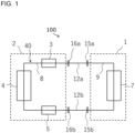
Fig. 1] Fig. 1 is a refrigerant circuit diagram illustrating the schematic configuration of an air-conditioning apparatus according to an embodiment. - [
Fig. 2] Fig. 2 is a perspective view illustrating the external configuration of an indoor unit of the air-conditioning apparatus according to the embodiment. - [
Fig. 3] Fig. 3 is a front view schematically illustrating the structure of the indoor unit of the air-conditioning apparatus according to the embodiment. - [
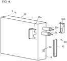
Fig. 4] Fig. 4 illustrates the indoor unit of the air-conditioning apparatus according to the embodiment before a cover portion is attached to a casing. - [
Fig. 5] Fig. 5 illustrates the indoor unit of the air-conditioning apparatus according to the embodiment with the cover portion attached to the casing. - [
Fig. 6] Fig. 6 is a front view schematically illustrating the indoor unit of the air-conditioning apparatus according to the embodiment with the cover portion attached to the casing. - [
Fig. 7] Fig. 7 is a perspective view illustrating a modification of the indoor unit of the air-conditioning apparatus according to the embodiment. - An air-
conditioning apparatus 100 according to an embodiment is described below.Fig. 1 is a refrigerant circuit diagram illustrating the schematic configuration of an air-conditioning apparatus 100. As illustrated inFig. 1 , the air-conditioning apparatus 100 includes arefrigerant circuit 40 to allow refrigerant to circulate therein. Therefrigerant circuit 40 has a configuration in which acompressor 3, a heat-source-side heat exchanger 4, apressure reducing device 5, and a load-side heat exchanger 7 are connected to each other in a ring form through refrigerant pipes. - A part of the
refrigerant circuit 40 including thecompressor 3, the heat-source-side heat exchanger 4, and thepressure reducing device 5 is accommodated in anoutdoor unit 2. Another part of therefrigerant circuit 40 including the load-side heat exchanger 7 is accommodated in anindoor unit 1.Extension pipes refrigerant circuit 40 are provided between theindoor unit 1 and theoutdoor unit 2. Theextension pipes internal refrigerant pipe 9 at refrigerantpipe connection portions internal refrigerant pipe 9 runs through the interior of theindoor unit 1. Theextension pipes refrigerant pipe 8 at refrigerantpipe connection portions refrigerant pipe 8 runs through the interior of theoutdoor unit 2. - The
indoor unit 1 is described below.Fig. 2 is a perspective view illustrating the exterior configuration of theindoor unit 1.Fig. 3 is a front view schematically illustrating the structure of theindoor unit 1. As illustrated inFigs. 2 and3 , theindoor unit 1 includes acasing 10 that is a cuboid casing. In thecasing 10, the load-side heat exchanger 7 and theinternal refrigerant pipe 9 are accommodated. The load-side heat exchanger 7 is a heat exchanger forming a part of therefrigerant circuit 40. Below the load-side heat exchanger 7, adrain pan 21 is provided to receive water condensed on the surface of the load-side heat exchanger 7. - Also in the
casing 10, acontrol box 25, afan 7f, and arefrigerant sensing unit 99 are accommodated. In thecontrol box 25, electrical components such as an electronic circuit board are accommodated. Thefan 7f generates a flow of air to an airflow passage running through the load-side heat exchanger 7. Therefrigerant sensing unit 99 is configured to sense refrigerant leakage. Therefrigerant sensing unit 99 is provided at a position near the bottom of thecasing 10 and in close proximity to a side portion R of thecasing 10 on which the refrigerantpipe connection portions pipe connection portions refrigerant sensing unit 99 senses the concentration of refrigerant in the air around therefrigerant sensing unit 99, and outputs a sensing signal to a control unit (not illustrated). The control unit performs the processing such as sounding an alarm when therefrigerant sensing unit 99 senses leakage of refrigerant. - The side portion R is one side portion of the
casing 10. On the outside of the side portion R, the refrigerantpipe connection portions internal refrigerant pipe 9 and theextension pipes extension pipes opening port 50 is formed at a position below the refrigerantpipe connection portions refrigerant sensing unit 99. The openingport 50 allows the interior of thecasing 10 to communicate with the exterior of thecasing 10. The openingport 50 has a plurality of small holes formed therein, through which the interior of thecasing 10 communicates with the exterior of thecasing 10. Note that the number of holes that make up theopening port 50, and the shape of the holes are not limited to the example illustrated in the drawings. It suffices that there is one or more holes. The holes may have any shape such as a slit shape. - On the outside of the side portion R of the
casing 10, acover portion 60 is provided to cover peripheries of the refrigerantpipe connection portions casing 10 with the openingport 50. In this manner, a refrigerantleakage sensing space 99s is formed as illustrated inFig. 3 . The refrigerantleakage sensing space 99s is made up of an outside space A of thecasing 10 and an inside space B of thecasing 10. The outside space A is covered by thecover portion 60. The inside space B communicates with the outside space A through the openingport 50. In the refrigerantleakage sensing space 99s, if refrigerant leaks from the refrigerantpipe connection portions refrigerant sensing unit 99 is provided in this refrigerantleakage sensing space 99s.Fig. 3 illustrates an example in which therefrigerant sensing unit 99 is provided in the inside space B of thecasing 10 within the refrigerantleakage sensing space 99s. - The
cover portion 60 has a structure made up of afirst part 61 and asecond part 62. Thefirst part 61 is configured to cover peripheries of the refrigerantpipe connection portions second part 62 is configured to cover the outside of thecasing 10 with the openingport 50. Thesefirst part 61 andsecond part 62 are combined and attached to thecasing 10 in such a manner that the space formed by thefirst part 61 and the space formed by thesecond part 62 communicate with each other. The outside space A of thecasing 10, covered by thecover portion 60 described above, refers to the entire space made up of the space formed by thefirst part 61 and the space formed by thesecond part 62, these spaces communicating with each other. Note that thecover portion 60 can be made of metal, resin or other material. -
Fig. 4 illustrates theindoor unit 1 before thecover portion 60 is attached to thecasing 10.Fig. 4 also illustrates theindoor unit 1 with theextension pipes pipe connection portions Fig. 5 illustrates theindoor unit 1 with thecover portion 60 attached to thecasing 10.Fig. 6 is a front view schematically illustrating theindoor unit 1 with thecover portion 60 attached to thecasing 10. - The
second part 62 is a vertically elongated part attached to the side portion R of thecasing 10 with its open upper end portion connected to thefirst part 61 and with the other end portions all closed. Thissecond part 62 is located in such a manner as to cover the outside of thecasing 10 with the openingport 50 with a predetermined spacing from thecasing 10. Thesecond part 62 may be attached to thecasing 10 by welding or by fixing using removable screws or other means. - The
first part 61 is attached to the side portion R of thecasing 10, and covers peripheries of the refrigerantpipe connection portions first part 61 is provided with through openingports extension pipes first part 61 is made up of aleft cover 61a and aright cover 61b that are divided into left and right from the section through which theextension pipes left cover 61a and theright cover 61b are combined in such a manner as to cover theextension pipes casing 10. Thus, thefirst part 61 can form the space in which its lower portion is opened, connecting to thesecond part 62, while the other portions of thefirst part 61 are all closed. - The
left cover 61a and theright cover 61b are attached to thecasing 10 by means of fixing using removable screws or other means. This allows either one or both of theleft cover 61a and theright cover 61b to be removed temporarily in the process of connecting or removing theextension pipes pipe connection portions extension pipes - In the configuration of the
cover portion 60 described above, if refrigerant leaks from the refrigerantpipe connection portions extension pipes first part 61. Thereafter, the leaking refrigerant flows through the space formed by thesecond part 62 and spreads to the interior of thecasing 10 from the openingport 50 as illustrated by the arrows inFig. 6 . When the leaking refrigerant flows into thecasing 10, therefrigerant sensing unit 99 provided in thecasing 10 can sense the leakage of the refrigerant. Particularly, in the present embodiment, therefrigerant sensing unit 99 is located near and below the openingport 50, and therefore can relatively quickly sense the leaking refrigerant flowing into thecasing 10 from the openingport 50. - As explained above, the air-
conditioning apparatus 100 includes therefrigerant circuit 40 configured to allow refrigerant to circulate therein, and thecasing 10 configured to accommodate therein the load-side heat exchanger 7 (heat exchanger) and the internalrefrigerant pipe 9. The load-side heat exchanger 7 forms a part of therefrigerant circuit 40. The air-conditioning apparatus 100 further includes the refrigerantpipe connection portions casing 10 and configured to connect the internalrefrigerant pipe 9 and theextension pipes extension pipes 12a and 12 being external refrigerant pipes. The air-conditioning apparatus 100 still further includes the openingport 50 and thecover portion 60. The openingport 50 is formed on thecasing 10 and configured to allow the interior of thecasing 10 to communicate with the exterior of thecasing 10. Thecover portion 60 is configured to cover peripheries of the refrigerantpipe connection portions casing 10 with the openingport 50. The air-conditioning apparatus 100 still further includes therefrigerant sensing unit 99 provided in the refrigerantleakage sensing space 99s and configured to sense leakage of refrigerant, the refrigerantleakage sensing space 99s being made up of the outside space A of thecasing 10 and the inside space B of thecasing 10, the outside space A being covered by thecover portion 60, the inside space B communicating with the outside space A through the openingport 50. Thus, in the configuration in which the refrigerantpipe connection portions casing 10 of theindoor unit 1, if refrigerant leaks from the refrigerantpipe connection portions leakage sensing space 99s formed by thecover portion 60, so that therefrigerant sensing unit 99 provided in the refrigerantleakage sensing space 99s can immediately sense the leakage of the refrigerant. - Note that in the above embodiment, the
refrigerant sensing unit 99 has been described as being provided in the inside space B of thecasing 10. However, the location of therefrigerant sensing unit 99 is not limited to this example. Therefrigerant sensing unit 99 may be provided in the outside space A of thecasing 10 covered by thecover portion 60 instead of, or in addition to, the inside space B of thecasing 10.Fig. 7 is a perspective view illustrating a modification of theindoor unit 1 of the air-conditioning apparatus 100 according to the embodiment. As illustrated inFig. 7 , in a case where arefrigerant sensing unit 199 is provided in the space A covered by thecover portion 60, at the time when leaking refrigerant reaches therefrigerant sensing unit 199 provided within thecover portion 60, therefrigerant sensing unit 199 can sense the leakage. Thus, the leakage of the refrigerant can be sensed relatively quickly. - In the above embodiment, the opening
port 50 has been described as being formed at a position on the lower side of the side portion R of thecasing 10 located closest to therefrigerant sensing unit 99. However, it suffices that the openingport 50 at least allows the interior of thecasing 10 to communicate with the exterior of thecasing 10. The position of theopening port 50 is not limited to the above example. Provided that the openingport 50 at least allows the interior of thecasing 10 to communicate with the exterior of thecasing 10, if refrigerant leaks from the refrigerantpipe connection portions port 50 to the interior of thecasing 10, so that therefrigerant sensing unit 99 provided in thecasing 10 can sense the leakage of the refrigerant. For example, the openingport 50 may be formed on another side portion of thecasing 10 other than the side portion R. Further, the openingport 50 may be formed at a position in or around the middle or on the upper side of thecasing 10. - Note that it is more preferable to form the
opening port 50 at a position on the upstream side of the airflow passage formed in thecasing 10 and running through the load-side heat exchanger 7, rather than the downstream side thereof. The reason for this is that when the leaking refrigerant may flow into thecasing 10 and enter the airflow passage, the openingport 50 causes this leaking refrigerant to flow toward the upstream side of the airflow passage rather than the downstream side, such that the leaking refrigerant is diluted with air in thecasing 10 and then discharged. - In the above embodiment, the
left cover 61a and theright cover 61b making up thefirst part 61 have been described as both being removably attached to thecasing 10. However, either theleft cover 61a or theright cover 61b may only be removable from thecasing 10. The reason for this is that when at least either one of them is removable from thecasing 10, the process of connecting theextension pipes pipe connection portions - In the above embodiment, the
cover portion 60 has been described as being made up of three separable components. However, thecover portion 60 may be made up of a single component into which these components are integrated, or may be made up of two or four or more separable components. - In the above embodiment, an example has been described in which the
cover portion 60 has a cuboid shape. However, the shape of thecover portion 60 is not limited to this example. Thecover portion 60 may have any shape, for example, a rounded prismatic shape or a hemispherical shape. - In the above embodiment, the configuration of the air-conditioning apparatus according to the present disclosure has been described as being applied to the indoor unit. However, this configuration may also be applied to the outdoor unit. The indoor unit or the outdoor unit, to which the configuration of the air-conditioning apparatus according to the present disclosure is applied, may be mounted on a floor, or may be mounted above a ceiling.
- 1: indoor unit, 2: outdoor unit, 3: compressor, 4: heat-source-side heat exchanger, 5: pressure reducing device, 7: load-side heat exchanger, 9: internal refrigerant pipe, 10: casing, 21: drain pan, 25: control box, 40: refrigerant circuit, 50: opening port, 60: cover portion, 61: first part, 62: second part, 7f: fan, 99, 199: refrigerant sensing unit, 99s: refrigerant leakage sensing space, 100: air-conditioning apparatus, 12a, 12b: extension pipe, 15a, 15b: refrigerant pipe connection portion, 61a: left cover, 61b: right cover, 63a, 63b: through opening port
Claims (5)
- An air-conditioning apparatus comprising:a refrigerant circuit configured to allow refrigerant to circulate therein;a casing configured to accommodate therein a heat exchanger and an internal refrigerant pipe, the heat exchanger and the internal refrigerant pipe each forming a part of the refrigerant circuit;a refrigerant pipe connection portion provided on an outside of one side portion of the casing, and configured to connect the internal refrigerant pipe and an external refrigerant pipe;an opening port formed on the casing, and configured to allow an interior of the casing to communicate with an exterior of the casing;a cover portion configured to cover a periphery of the refrigerant pipe connection portion, and cover, from outside of the casing, the opening port; anda refrigerant sensing unit provided in a refrigerant leakage sensing space, and configured to sense leakage of the refrigerant, the refrigerant leakage sensing space being made up of an outside space of the casing and an inside space of the casing, the outside space being covered by the cover portion, the inside space communicating with the outside space through the opening port.
- The air-conditioning apparatus of claim 1, wherein the refrigerant sensing unit is provided in the inside space of the casing in the refrigerant leakage sensing space, and the opening port is formed on a side portion of the casing located closest to the refrigerant sensing unit or on a side portion of the casing located second closest to the refrigerant sensing unit.
- The air-conditioning apparatus of claim 1, wherein the refrigerant sensing unit is provided in the outside space of the casing in the refrigerant leakage sensing space, the outside space being covered by the cover portion.
- The air-conditioning apparatus of any one of claims 1 to 3, wherein the cover portion includes a first part and a second part, the first part being configured to cover the periphery of the refrigerant pipe connection portion, the second part being configured to cover, from outside of the casing, the opening port.
- The air-conditioning apparatus of claim 4, wherein the first part is made up of at least two divided pieces divided from a section through which the external refrigerant pipe penetrates.
Applications Claiming Priority (1)
| Application Number | Priority Date | Filing Date | Title |
|---|---|---|---|
| PCT/JP2020/042844 WO2022107220A1 (en) | 2020-11-17 | 2020-11-17 | Air-conditioning device |
Publications (3)
| Publication Number | Publication Date |
|---|---|
| EP4249831A1 true EP4249831A1 (en) | 2023-09-27 |
| EP4249831A4 EP4249831A4 (en) | 2024-01-03 |
| EP4249831B1 EP4249831B1 (en) | 2026-01-21 |
Family
ID=81708517
Family Applications (1)
| Application Number | Title | Priority Date | Filing Date |
|---|---|---|---|
| EP20962384.2A Active EP4249831B1 (en) | 2020-11-17 | 2020-11-17 | Air-conditioning device |
Country Status (4)
| Country | Link |
|---|---|
| US (1) | US12320535B2 (en) |
| EP (1) | EP4249831B1 (en) |
| JP (1) | JP7433474B2 (en) |
| WO (1) | WO2022107220A1 (en) |
Families Citing this family (4)
| Publication number | Priority date | Publication date | Assignee | Title |
|---|---|---|---|---|
| JP7381956B1 (en) * | 2022-09-27 | 2023-11-16 | ダイキン工業株式会社 | Air conditioner component unit and air conditioner |
| WO2024247259A1 (en) * | 2023-06-02 | 2024-12-05 | 三菱電機株式会社 | Cover member and indoor unit of air conditioner |
| CN116951577B (en) * | 2023-09-04 | 2025-12-02 | 广东美的制冷设备有限公司 | Air conditioner indoor unit and air conditioner |
| EP4733682A1 (en) | 2024-10-24 | 2026-04-29 | Daikin Industries, Ltd. | Outdoor unit and method of assembling outdoor unit |
Family Cites Families (10)
| Publication number | Priority date | Publication date | Assignee | Title |
|---|---|---|---|---|
| JP3311588B2 (en) * | 1996-07-12 | 2002-08-05 | 仁吉 合澤 | Refrigerant piping unit for heat exchanger |
| JP4081681B2 (en) * | 2003-11-14 | 2008-04-30 | 三菱電機株式会社 | Indoor unit and air conditioner |
| US10760839B2 (en) | 2015-03-26 | 2020-09-01 | Mitsubishi Electric Corporation | Indoor unit of air-conditioning apparatus having leaked refrigerant ventilation |
| JP6519360B2 (en) | 2015-07-01 | 2019-05-29 | ダイキン工業株式会社 | Indoor unit of air conditioner |
| JP7332273B2 (en) | 2018-02-09 | 2023-08-23 | 三菱重工サーマルシステムズ株式会社 | air conditioner |
| JP7004836B2 (en) | 2018-09-18 | 2022-01-21 | 三菱電機株式会社 | Refrigeration cycle device |
| JP6906168B2 (en) * | 2019-02-20 | 2021-07-21 | パナソニックIpマネジメント株式会社 | Indoor unit |
| EP3719405B1 (en) | 2019-04-02 | 2023-08-09 | Panasonic Intellectual Property Management Co., Ltd. | Indoor unit of air conditioning apparatus |
| JP6754988B1 (en) * | 2019-04-02 | 2020-09-16 | パナソニックIpマネジメント株式会社 | Indoor unit of air conditioner |
| US11525602B2 (en) * | 2019-09-26 | 2022-12-13 | Trane International Inc. | Cover panels for climate control system housings and methods related thereto |
-
2020
- 2020-11-17 JP JP2022563285A patent/JP7433474B2/en active Active
- 2020-11-17 EP EP20962384.2A patent/EP4249831B1/en active Active
- 2020-11-17 US US18/044,589 patent/US12320535B2/en active Active
- 2020-11-17 WO PCT/JP2020/042844 patent/WO2022107220A1/en not_active Ceased
Also Published As
| Publication number | Publication date |
|---|---|
| US20230332787A1 (en) | 2023-10-19 |
| US12320535B2 (en) | 2025-06-03 |
| WO2022107220A1 (en) | 2022-05-27 |
| EP4249831A4 (en) | 2024-01-03 |
| EP4249831B1 (en) | 2026-01-21 |
| JP7433474B2 (en) | 2024-02-19 |
| JPWO2022107220A1 (en) | 2022-05-27 |
Similar Documents
| Publication | Publication Date | Title |
|---|---|---|
| US12320535B2 (en) | Air-conditioning apparatus | |
| EP3214383B1 (en) | Air conditioner | |
| CN107076454B (en) | Indoor unit of air conditioner | |
| JP7004836B2 (en) | Refrigeration cycle device | |
| US20210041114A1 (en) | Indoor unit of air-conditioning apparatus, and air-conditioning apparatus including the indoor unit | |
| EP3653944A1 (en) | Indoor unit for air conditioner comprising refrigerant detection sensor | |
| JP5983707B2 (en) | Air conditioner indoor unit | |
| EP3214391A1 (en) | Air conditioner | |
| EP4033165A1 (en) | Air conditioner | |
| CN206191781U (en) | Outdoor unit of air conditioner | |
| JPWO2017208348A1 (en) | Air conditioner indoor unit | |
| JP6906168B2 (en) | Indoor unit | |
| JPWO2019239630A1 (en) | Outdoor unit | |
| EP3719405B1 (en) | Indoor unit of air conditioning apparatus | |
| EP2098797A1 (en) | Air conditioner | |
| JPH08296869A (en) | Air-conditioning equipment | |
| WO2017195335A1 (en) | Outdoor unit of air conditioner | |
| EP2990242A1 (en) | Air conditioning device for vehicle | |
| JP2017003223A (en) | Indoor unit for duct type air conditioner | |
| JP7018964B2 (en) | Indoor unit of air conditioner | |
| CN113614466B (en) | Indoor unit of air conditioner | |
| CN218672392U (en) | Indoor unit of air conditioner | |
| JP6482669B2 (en) | Air conditioner indoor unit | |
| CN223807262U (en) | Indoor unit, air conditioner | |
| KR101347574B1 (en) | Air conditioner |
Legal Events
| Date | Code | Title | Description |
|---|---|---|---|
| STAA | Information on the status of an ep patent application or granted ep patent |
Free format text: STATUS: THE INTERNATIONAL PUBLICATION HAS BEEN MADE |
|
| PUAI | Public reference made under article 153(3) epc to a published international application that has entered the european phase |
Free format text: ORIGINAL CODE: 0009012 |
|
| STAA | Information on the status of an ep patent application or granted ep patent |
Free format text: STATUS: REQUEST FOR EXAMINATION WAS MADE |
|
| 17P | Request for examination filed |
Effective date: 20230426 |
|
| AK | Designated contracting states |
Kind code of ref document: A1 Designated state(s): AL AT BE BG CH CY CZ DE DK EE ES FI FR GB GR HR HU IE IS IT LI LT LU LV MC MK MT NL NO PL PT RO RS SE SI SK SM TR |
|
| A4 | Supplementary search report drawn up and despatched |
Effective date: 20231204 |
|
| RIC1 | Information provided on ipc code assigned before grant |
Ipc: F24F 11/89 20180101ALI20231128BHEP Ipc: F24F 11/36 20180101ALI20231128BHEP Ipc: F24F 13/20 20060101ALI20231128BHEP Ipc: F25B 49/02 20060101AFI20231128BHEP |
|
| DAV | Request for validation of the european patent (deleted) | ||
| DAX | Request for extension of the european patent (deleted) | ||
| GRAP | Despatch of communication of intention to grant a patent |
Free format text: ORIGINAL CODE: EPIDOSNIGR1 |
|
| STAA | Information on the status of an ep patent application or granted ep patent |
Free format text: STATUS: GRANT OF PATENT IS INTENDED |
|
| INTG | Intention to grant announced |
Effective date: 20250402 |
|
| GRAJ | Information related to disapproval of communication of intention to grant by the applicant or resumption of examination proceedings by the epo deleted |
Free format text: ORIGINAL CODE: EPIDOSDIGR1 |
|
| STAA | Information on the status of an ep patent application or granted ep patent |
Free format text: STATUS: REQUEST FOR EXAMINATION WAS MADE |
|
| INTC | Intention to grant announced (deleted) | ||
| REG | Reference to a national code |
Ref country code: DE Ref legal event code: R079 Free format text: PREVIOUS MAIN CLASS: F25B0049020000 Ipc: F24F0011320000 Ref country code: DE Ref legal event code: R079 Ref document number: 602020065718 Country of ref document: DE Free format text: PREVIOUS MAIN CLASS: F25B0049020000 Ipc: F24F0011320000 |
|
| GRAP | Despatch of communication of intention to grant a patent |
Free format text: ORIGINAL CODE: EPIDOSNIGR1 |
|
| STAA | Information on the status of an ep patent application or granted ep patent |
Free format text: STATUS: GRANT OF PATENT IS INTENDED |
|
| RIC1 | Information provided on ipc code assigned before grant |
Ipc: F24F 11/32 20180101AFI20250822BHEP Ipc: F25B 49/02 20060101ALI20250822BHEP Ipc: F24F 13/20 20060101ALI20250822BHEP Ipc: F24F 11/36 20180101ALI20250822BHEP Ipc: F24F 11/89 20180101ALI20250822BHEP |
|
| INTG | Intention to grant announced |
Effective date: 20250909 |
|
| GRAS | Grant fee paid |
Free format text: ORIGINAL CODE: EPIDOSNIGR3 |
|
| GRAA | (expected) grant |
Free format text: ORIGINAL CODE: 0009210 |
|
| STAA | Information on the status of an ep patent application or granted ep patent |
Free format text: STATUS: THE PATENT HAS BEEN GRANTED |
|
| AK | Designated contracting states |
Kind code of ref document: B1 Designated state(s): AL AT BE BG CH CY CZ DE DK EE ES FI FR GB GR HR HU IE IS IT LI LT LU LV MC MK MT NL NO PL PT RO RS SE SI SK SM TR |
|
| REG | Reference to a national code |
Ref country code: CH Ref legal event code: F10 Free format text: ST27 STATUS EVENT CODE: U-0-0-F10-F00 (AS PROVIDED BY THE NATIONAL OFFICE) Effective date: 20260121 |
|
| REG | Reference to a national code |
Ref country code: DE Ref legal event code: R096 Ref document number: 602020065718 Country of ref document: DE |
|
| REG | Reference to a national code |
Ref country code: IE Ref legal event code: FG4D |