EP4249821A1 - Indoor unit, and refrigeration cycle device - Google Patents
Indoor unit, and refrigeration cycle device Download PDFInfo
- Publication number
- EP4249821A1 EP4249821A1 EP20962373.5A EP20962373A EP4249821A1 EP 4249821 A1 EP4249821 A1 EP 4249821A1 EP 20962373 A EP20962373 A EP 20962373A EP 4249821 A1 EP4249821 A1 EP 4249821A1
- Authority
- EP
- European Patent Office
- Prior art keywords
- air
- fan
- indoor unit
- space
- main body
- Prior art date
- Legal status (The legal status is an assumption and is not a legal conclusion. Google has not performed a legal analysis and makes no representation as to the accuracy of the status listed.)
- Withdrawn
Links
Images


Classifications
-
- F—MECHANICAL ENGINEERING; LIGHTING; HEATING; WEAPONS; BLASTING
- F24—HEATING; RANGES; VENTILATING
- F24F—AIR-CONDITIONING; AIR-HUMIDIFICATION; VENTILATION; USE OF AIR CURRENTS FOR SCREENING
- F24F1/00—Room units for air-conditioning, e.g. separate or self-contained units or units receiving primary air from a central station
- F24F1/0007—Indoor units, e.g. fan coil units
- F24F1/0018—Indoor units, e.g. fan coil units characterised by fans
- F24F1/0022—Centrifugal or radial fans
-
- F—MECHANICAL ENGINEERING; LIGHTING; HEATING; WEAPONS; BLASTING
- F24—HEATING; RANGES; VENTILATING
- F24F—AIR-CONDITIONING; AIR-HUMIDIFICATION; VENTILATION; USE OF AIR CURRENTS FOR SCREENING
- F24F1/00—Room units for air-conditioning, e.g. separate or self-contained units or units receiving primary air from a central station
- F24F1/0007—Indoor units, e.g. fan coil units
- F24F1/0043—Indoor units, e.g. fan coil units characterised by mounting arrangements
- F24F1/0047—Indoor units, e.g. fan coil units characterised by mounting arrangements mounted in the ceiling or at the ceiling
-
- F—MECHANICAL ENGINEERING; LIGHTING; HEATING; WEAPONS; BLASTING
- F24—HEATING; RANGES; VENTILATING
- F24F—AIR-CONDITIONING; AIR-HUMIDIFICATION; VENTILATION; USE OF AIR CURRENTS FOR SCREENING
- F24F13/00—Details common to, or for air-conditioning, air-humidification, ventilation or use of air currents for screening
- F24F13/08—Air-flow control members, e.g. louvres, grilles, flaps or guide plates
- F24F13/081—Air-flow control members, e.g. louvres, grilles, flaps or guide plates for guiding air around a curve
-
- F—MECHANICAL ENGINEERING; LIGHTING; HEATING; WEAPONS; BLASTING
- F24—HEATING; RANGES; VENTILATING
- F24F—AIR-CONDITIONING; AIR-HUMIDIFICATION; VENTILATION; USE OF AIR CURRENTS FOR SCREENING
- F24F13/00—Details common to, or for air-conditioning, air-humidification, ventilation or use of air currents for screening
- F24F13/20—Casings or covers
-
- F—MECHANICAL ENGINEERING; LIGHTING; HEATING; WEAPONS; BLASTING
- F24—HEATING; RANGES; VENTILATING
- F24F—AIR-CONDITIONING; AIR-HUMIDIFICATION; VENTILATION; USE OF AIR CURRENTS FOR SCREENING
- F24F11/00—Control or safety arrangements
- F24F11/89—Arrangement or mounting of control or safety devices
-
- F—MECHANICAL ENGINEERING; LIGHTING; HEATING; WEAPONS; BLASTING
- F24—HEATING; RANGES; VENTILATING
- F24F—AIR-CONDITIONING; AIR-HUMIDIFICATION; VENTILATION; USE OF AIR CURRENTS FOR SCREENING
- F24F13/00—Details common to, or for air-conditioning, air-humidification, ventilation or use of air currents for screening
- F24F13/24—Means for preventing or suppressing noise
Definitions
- the present disclosure relates to an indoor unit including a fan, a bell mouth, and an electric component box, and also relates to a refrigeration cycle device.
- Patent Literature 1 discloses a four-way cassette indoor unit including a fan, a bell mouth, and an electric equipment box.
- the electric equipment box is installed, closing a portion of the opening of the bell mouth, and an electric-equipment-box support rib that supports the electric equipment box is provided between the bell mouth and the electric equipment box.
- Patent Literature 1 Japanese Unexamined Patent Application Publication No. 2017-122525
- the present disclosure has been made to solve the above problems, and it is an object of the present disclosure to provide an indoor unit and a refrigeration cycle device that reduce generation of noise, while preventing the manufacturing costs from increasing.
- An indoor unit includes: a main body that has an opening near an air-conditioning target space and is attached to an installation section; a panel that has an air inlet through which air is suctioned and an air outlet through which the suctioned air is discharged, and covers the opening of the main body; a fan that is provided to the main body and generates flow of air that is suctioned from the air inlet of the panel and blown out from the air outlet of the panel; a bell mouth that is provided upstream of the fan in the main body and guides the air suctioned from the air inlet toward the fan; and an electric component box that is provided upstream of the bell mouth in the main body, to thereby define an air-flowing space between the electric component box and the bell mouth, and accommodates a control unit that controls operation of the fan.
- the space is defined between the electric component box and the bell mouth. This allows air that enters from the upstream side of the electric component box to pass through the electric component box and thereafter enter the space. Thus, a dead air region is not generated downstream of the electric component box. This prevents ambient air, including air entering from the upstream side of the electric component box, and air entering from the bell mouth near the electric component box, from colliding with each other. Therefore, flow of the air is prevented from becoming turbulent, which can reduce generation of noise. Since it is unnecessary to perform machining on the electric component box and other parts, the manufacturing costs can be prevented from increasing.
- Fig. 1 is a perspective view illustrating an indoor unit 200 according to Embodiment 1.
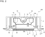
- Fig. 2 is a side transparent view illustrating the indoor unit 200 according to Embodiment 1.
- the indoor unit 200 is, for example, a four-way cassette indoor unit 200.
- the indoor unit 200 includes a main body 20, a panel 25, wind deflectors 13, a heat exchanger 3, a drain pan 16, a fan 18, a bell mouth 14, and an electric component box 30.
- the main body 20 is a bottomed rectangular cylindrical housing attached to an installation section 15 such as a ceiling surface.
- the main body 20 includes a rectangular-shaped main body top plate 5 located on the far side of the installation section 15, and four main body side plates 4 extending from the four sides of the main body top plate 5 toward an air-conditioning target space 17.
- the main body 20 has an opening 20a on one side thereof opposite to the main body top plate 5.
- the indoor unit 200 of a ceiling-mounted refrigeration cycle device 1000 (see Fig. 9 ) is illustrated as an example, in which the main body 20 is mounted to the ceiling on the far side of the installation section 15.
- the panel 25 covers the opening 20a of the main body 20, and includes a cosmetic panel 6 and a suction panel 7.
- the panel 25 may be made of, for example, sheet metal or resin.
- the cosmetic panel 6 is a rectangular frame-like part that is removably attached to the main body 20, and covers the edge portion of the opening 20a of the main body 20. At opposite end portions on the longer sides of the cosmetic panel 6, longitudinally-extending holes are formed. Note that the cosmetic panel 6 is positioned substantially flush with the installation section 15.
- the suction panel 7 is a rectangular frame-like part located inside the frame of the cosmetic panel 6 and removably attached to the cosmetic panel 6. The suction panel 7 covers the center of the opening 20a of the main body 20. A surface of the suction panel 7 facing toward the air-conditioning target space 17 is a substantially horizontal surface.
- an air inlet 21 is formed through which air in the air-conditioning target space 17 is suctioned.
- the air inlet 21 is formed on the central side of the main body 20. Further, in the opening 20a of the main body 20, the holes extending along the edge portions on the longer sides of the cosmetic panel 6 serve as an air outlet 9.
- the air outlet 9 is an opening through which air suctioned from the air inlet 21 is discharged. Note that while in the present Embodiment 1, an example is illustrated in which there are four holes extending along the edge portions on the four sides of the cosmetic panel 6 to serve as air outlets 9, the number of the air outlets 9 may be one to three or five or more.
- Each of the wind deflectors 13 is provided to each of the air outlets 9, and changes its angle to adjust the direction of air to be discharged through the air outlet 9.
- the heat exchanger 3 is provided on an air passage connecting the air inlet 21 and the air outlet 9 on the radially outer side of the fan 18.
- the heat exchanger 3 allows the air suctioned from the air inlet 21 to exchange heat with refrigerant.
- the heat exchanger 3 is, for example, a fin-and-tube heat exchanger including a plurality of fins (not illustrated) and a plurality of heat transfer tubes (not illustrated).
- the plurality of fins are arranged with a predetermined spacing therebetween in the horizontal direction.
- the plurality of heat transfer tubes penetrate the plurality of fins.
- the heat transfer tubes are connected to an outdoor unit 100 (see Fig. 9 ) by a gas pipe 300 and a liquid pipe 400.
- the drain pan 16 is provided below the heat exchanger 3 to receive condensation water generated by cooling air in the air-conditioning target space 17 in the heat exchanger 3.
- the filter 8 is provided between the suction panel 7 and the fan 18 to remove dust from the air suctioned from the air inlet 21.
- the size of the outer shape of the filter 8 is approximately equal to that of the suction panel 7.
- the fan 18 is provided at the center in the interior of the main body 20, and generates flow of air that is suctioned from the air inlet 21 and discharged from the air outlet 9.
- the fan 18 includes a fan motor 2, a shaft 2a, and a centrifugal fan 1.
- the fan motor 2 is supported on the lower surface of the main body top plate 5, and rotationally drives the centrifugal fan 1.
- the shaft 2a is a rotational shaft extending downward from the fan motor 2.
- the centrifugal fan 1 is a turbo fan, and includes a main plate 10, a plurality of blades 12, and a side plate 11.
- the main plate 10 includes a boss that is a fixed portion at which the main plate 10 is fixed to the shaft 2a.
- the side plate 11 defines the air passage.
- the blades 12 rotate by being rotationally driven by the fan motor 2.
- a fan air inlet 18a through which air is suctioned, and a fan air outlet 18b through which air is discharged are formed.
- the centrifugal fan 1 suctions air into the interior of the main body 20 from the air inlet 21, and blows out the suctioned air from the air outlet 9 to the room that is the air-conditioning target space 17.
- the bell mouth 14 is a cylindrical curved-surface part provided between the suction panel 7 and the centrifugal fan 1 of the fan 18, and having a diameter that gradually decreases from the upstream side of air to be delivered to the fan 18 toward the downstream side of the air.
- the bell mouth 14 is a cylindrical part and has a bell mouth opening 14a.
- the bell mouth 14 is configured to guide air that enters the fan 18.
- the bell mouth 14 is provided to partition the interior space of the main body 20 into an upstream-side space located between the air inlet 21 of the indoor unit 200 and the fan air inlet 18a of the fan 18, and a downstream-side space located between the fan air outlet 18b of the fan 18 and the air outlet 9 of the indoor unit 200.
- the electric component box 30 is a box-shaped part that accommodates a control unit (not illustrated) that controls operation of the fan 18 and other devices.
- the electric component box 30 is provided upstream of the bell mouth 14 in the main body 20. As illustrated in Fig. 1 , the electric component box 30 is located at the edge portion on one of the four sides of the opening 20a of the main body 20, and closes a portion of the opening 20a.
- An air-flowing space 40 is defined between the electric component box 30 and the bell mouth 14. That is, the electric component box 30 and the bell mouth 14 are spaced from each other with a predetermined distance between them. As described above, the electric component box 30 is provided upstream of the bell mouth 14 in the main body 20, to thereby define the air-flowing space 40 between the electric component box 30 and the bell mouth 14.
- the air 50 from which dust has been removed by the filter 8, partially passes through the vicinity of the electric component box 30, and then enters the space 40 once on the downstream side of the electric component box 30.
- the air 50 having entered the space 40 stays in the space 40, and thereafter flows out from the space 40 and enters the interior of the bell mouth 14.
- the fan 18 generates flow of the air 50 such that part of the air 50 suctioned from the air inlet 21 passes through the space 40 and thereafter flows toward the bell mouth 14.
- the space 40 is defined between the electric component box 30 and the bell mouth 14. This allows air that enters from the upstream side of the electric component box 30 to pass through the electric component box 30 and thereafter enter the space 40. Thus, a dead air region is not generated downstream of the electric component box 30. This prevents ambient air, including air entering from the upstream side of the electric component box 30, and air entering from the bell mouth 14 near the electric component box 30, from colliding with each other. Therefore, flow of the air is prevented from becoming turbulent, which can reduce generation of noise.
- the indoor unit 200 according to the present Embodiment 1 can reduce generation of noise without increasing the manufacturing costs. Since air passes through the space 40, the air is suctioned into the fan 18 in a circumferentially uniform distribution. As described above, the uniform distribution of suctioned air prevents the flow of air entering the fan 18 from becoming turbulent, so that power consumption of the fan 18 is reduced and generation of noise is also reduced.
- Fig. 3 is a side transparent view illustrating an indoor unit 200e according to Comparative Example.
- the function of the indoor unit 200e according to Comparative Example is described for the purpose of easily understanding the function of the indoor unit 200 according to the present Embodiment 1.
- the space 40 is not defined between the electric component box 30 and the bell mouth 14. Due to this configuration, a dead air region 60 is generated downstream of the electric component box 30 in the flow of air.
- the turbulent air flow enters into the fan 18 noise is generated. Note that in the indoor unit 200e in Comparative Example, assuming that the electric component box 30 and the control unit provided in the electric component box 30 are partially recessed along the bell mouth opening 14a to eliminate the dead air region 60, the manufacturing costs are increased accordingly.
- the space 40 is defined between the electric component box 30 and the bell mouth 14.
- the air that enters from the upstream side of the electric component box 30 passes through the electric component box 30, and thereafter enters the space 40. Therefore, generation of noise can be reduced, while the manufacturing costs are prevented from increasing.
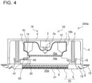
- Fig. 4 is a side transparent view illustrating an indoor unit 200a according to Embodiment 2.
- Fig. 5 is a bottom view illustrating the indoor unit 200a according to Embodiment 2.
- the present Embodiment 2 is different from Embodiment 1 in that the indoor unit 200a includes a flow regulation guide 41.
- the same components as those in Embodiment 1 are denoted by the same reference numerals and thus descriptions thereof are omitted, while the different points from Embodiment 1 are mainly described.
- the flow regulation guide 41 is provided in the space 40 and guides the air entering the space 40 toward the bell mouth 14.
- the flow regulation guide 41 is configured to change the direction of air having entered the space 40 between the electric component box 30 and the bell mouth 14 to a direction toward the fan air inlet 18a of the fan 18.
- the flow regulation guide 41 is connected at its upper end portion to the bell mouth 14, while being connected at its lower end portion to the electric component box 30.
- the flow regulation guide 41 is installed to partition off the space 40 between the bell mouth 14 and the electric component box 30.
- the flow regulation guide 41 is provided near the center of the electric component box 30.
- the inner circumferential end of the flow regulation guide 41 is positioned on the outer circumferential side relative to the bell mouth opening 14a. Note that the flow regulation guide 41 may be formed integrally with the bell mouth 14 into a single component.
- the number of the flow regulation guide 41 is one in the space 40 in the circumferential direction about the rotational shaft of the fan 18. That is, the flow regulation guide 41 is arranged at a single location in the circumferential direction about the rotational shaft of the fan 18. This arrangement does not cause such a problem that it is difficult to reduce generation of noise, when the flow regulation guides 41 are installed at two or more locations and consequently air does not flow between the flow regulation guides 41.
- the indoor unit 200a further includes the flow regulation guide 41 that is provided in the space 40 and guides the air entering the space 40 toward the bell mouth 14.
- the flow regulation guide 41 changes the direction of air entering from the lateral direction of the electric component box 30 to a direction toward the fan 18, so that turbulence of the airflow generated by a collision of the air is reduced and the noise level is also decreased.
- the number of the flow regulation guide 41 is one in the space 40 in the circumferential direction about the rotational shaft of the fan 18. This arrangement does not cause such a problem that it is difficult to reduce generation of noise, when the flow regulation guides 41 are installed at two or more locations and consequently air does not flow between the flow regulation guides 41. Therefore, the number of the flow regulation guide 41 is one, so that air can easily enter the space 40 between the electric component box 30 and the bell mouth 14 in its entirety.
- Fig. 6 is a bottom view illustrating an indoor unit 200b according to Embodiment 3.
- the present Embodiment 3 is different from Embodiment 1 in location where the flow regulation guide 41 is installed.
- the same components as those in Embodiments 1 and 2 are denoted by the same reference numerals and thus descriptions thereof are omitted, while the different points from Embodiments 1 and 2 are mainly described.
- the flow regulation guide 41 is provided at an end portion of the space 40 in the circumferential direction about the rotational shaft of the fan 18.
- the flow regulation guide 41 is provided at an end portion of the space 40 directed opposite to the rotation direction R of the fan 18.
- the flow regulation guide 41 may be provided at another end portion of the space 40 directed toward the rotation direction R of the fan 18.
- the flow regulation guide 41 is provided at an end portion of the space 40 in the circumferential direction about the rotational shaft of the fan 18. Due to this configuration, the space 40 is partitioned by the flow regulation guide 41 into two, one of which is a larger space 40 than the other smaller space 40. This allows the air to enter the space 40 between the electric component box 30 and the bell mouth 14 mainly from one side of the electric component box 30. Therefore, turbulence of the airflow caused by a collision of the air is further reduced and the noise level is decreased.
- Fig. 7 is a bottom view illustrating an indoor unit 200c according to Embodiment 4.
- the present Embodiment 4 is different from Embodiments 2 and 3 in that the flow regulation guide 41 includes a pair of side surfaces 42.
- the same components as those in Embodiments 1 to 3 are denoted by the same reference numerals and thus descriptions thereof are omitted, while the different points from Embodiments 1 to 3 are mainly described.
- the flow regulation guide 41 includes the pair of side surfaces 42 facing each other in the circumferential direction about the rotational shaft of the fan 18. The distance between the pair of side surfaces 42 is decreased toward the rotational shaft of the fan 18.
- the pair of side surfaces 42 of the flow regulation guide 41 protrudes toward the direction in which the side surfaces 42 face each other. That is, the side surfaces 42 are recessed on the outer side of the flow regulation guide 41.
- the flow regulation guide 41 may have a hollow structure in its surrounded area by the side surfaces 42.
- the flow regulation guide 41 includes the pair of side surfaces 42 facing each other in the circumferential direction about the rotational shaft of the fan 18, and the distance between the pair of side surfaces 42 is decreased toward the rotational shaft of the fan 18. Due to this configuration, the air that has entered from the lateral direction of the flow regulation guide 41 and collided against the flow regulation guide 41 flows smoothly toward the bell mouth 14.
- the pair of side surfaces 42 of the flow regulation guide 41 protrudes toward the direction in which the side surfaces 42 face each other. This allows the air to flow along the recessed surfaces, and thus helps the air to flow more smoothly, compared to when the side surfaces 42 are flat.
- the material costs of the flow regulation guide 41 can be reduced and the weight of the flow regulation guide 41 can also be reduced.
- Fig. 8 is a side transparent view illustrating an indoor unit 200d according to Embodiment 5.
- the present Embodiment 5 is different from Embodiments 2 to 4 in shape of the electric component box 30.
- the same components as those in Embodiments 1 to 4 are denoted by the same reference numerals and thus descriptions thereof are omitted, while the different points from Embodiments 1 to 4 are mainly described.
- an upstream-side end portion 31 and a downstream-side end portion 32 on the side surface 42 of the electric component box 30, which faces toward the fan 18, have a curved surface.
- the upstream-side end portion 31 has a radius of curvature larger than that of the downstream-side end portion 32.
- the range J of the curved-surface shape of the upstream-side end portion 31 is preferably equal to or greater than one-third of the height H of the electric component box 30.
- the upstream-side end portion 31 and the downstream-side end portion 32 on the side surface 42 of the electric component box 30, which faces toward the fan 18, have a curved surface, and the upstream-side end portion 31 has a radius of curvature larger than that of the downstream-side end portion 32.
- the upstream-side end portion 31 of the electric component box 30 has a radius of curvature larger than that of the downstream-side end portion 32 to help smooth the flow of air on the upstream side.
- the range of the curved-surface shape of the upstream-side end portion 31 is equal to or greater than one-third of the height of the electric component box 30. This helps air to easily flow along the shape of the electric component box 30 to further smooth the flow of air.
- Fig. 9 illustrates a circuit diagram of the refrigeration cycle device 1000 according to Embodiment 6.
- the refrigeration cycle device 1000 including the indoor unit 200 in any one of Embodiments 1 to 5 is described.
- the refrigeration cycle device 1000 is, for example, an air-conditioning apparatus that conditions air in the air-conditioning target space 17.
- the refrigeration cycle device 1000 includes the outdoor unit 100 and the indoor unit 200.
- the outdoor unit 100 and the indoor unit 200 are connected by the gas pipe 300 through which gas refrigerant flows and the liquid pipe 400 through which liquid refrigerant or two-phase gas-liquid refrigerant flows.
- the outdoor unit 100 is provided with a compressor 101, a flow switching device 102, an outdoor heat exchanger 103, an outdoor fan 104, and an expansion unit 105.
- the indoor unit 200 is provided with the heat exchanger 3 and the fan 18.
- the compressor 101, the flow switching device 102, the outdoor heat exchanger 103, the expansion unit 105, and the heat exchanger 3 are connected by connection pipes, forming a refrigerant circuit.
- the compressor 101 is configured to suction refrigerant in a low-temperature low-pressure state, compress the suctioned refrigerant into a high-temperature high-pressure state, and discharge the compressed refrigerant.
- the compressor 101 includes, for example, an inverter device that optionally changes the operational frequency to minutely change the capacity of the compressor 101.
- the capacity of the compressor 101 refers to the amount of refrigerant to be delivered per unit time.
- the flow switching device 102 is configured to switch between the refrigerant flow directions in the refrigerant circuit based on an instruction from the control unit (not illustrated).
- the flow switching device 102 is, for example, a four-way valve.
- the outdoor heat exchanger 103 is configured to exchange heat, for example, between outside air and refrigerant.
- the outdoor heat exchanger 103 serves as a condenser during cooling operation, while serving as an evaporator during heating operation.
- the outdoor fan 104 is a device that delivers outside air to the outdoor heat exchanger 103.
- the outdoor fan 104 may include the centrifugal fan 1 similarly to the fan 18.
- the outdoor fan 104 may minutely change the rotation speed of the centrifugal fan 1 by an inverter device or other device optionally changing the operational frequency of the motor.
- the expansion unit 105 is a pressure reducing valve or an expansion valve that reduces the pressure of refrigerant to expand the refrigerant.
- the expansion unit 105 is, for example, an electronic expansion valve whose opening degree is adjustable.
- the heat exchanger 3 is configured to exchange heat, for example, between room air and refrigerant.
- the heat exchanger 3 serves as an evaporator during cooling operation, while serving as a condenser during heating operation.
- the fan 18 is a device that delivers room air to the heat exchanger 3.
- the operational speed of the fan 18 is set by, for example, a user.
- cooling operation refrigerant suctioned into the compressor 101 is compressed by the compressor 101 into a high-temperature high-pressure gas state, and then discharged.
- the refrigerant in a high-temperature high-pressure gas state discharged from the compressor 101 passes through the flow switching device 102, and enters the outdoor heat exchanger 103 that serves as a condenser.
- the outdoor heat exchanger 103 the refrigerant exchanges heat with the outside air delivered by the outdoor fan 104, and consequently condenses and liquifies.
- the refrigerant having condensed into a liquid state enters the expansion unit 105, and is expanded and reduced in pressure in the expansion unit 105 to be brought into a low-temperature low-pressure two-phase gas-liquid state.
- the refrigerant in a two-phase gas-liquid state enters the heat exchanger 3 that serves as an evaporator.
- the heat exchanger 3 the refrigerant exchanges heat with the room air delivered by the fan 18, and consequently evaporates and gasifies. At this time, the room air is cooled and thus cooling is performed in the room.
- the refrigerant having evaporated into a low-temperature low-pressure gas state passes through the flow switching device 102 and is suctioned into the compressor 101.
- heating operation is explained.
- refrigerant suctioned into the compressor 101 is compressed by the compressor 101 into a high-temperature high-pressure gas state, and then discharged.
- the refrigerant in a high-temperature high-pressure gas state discharged from the compressor 101 passes through the flow switching device 102, and enters the heat exchanger 3 that serves as a condenser.
- the heat exchanger 3 the refrigerant exchanges heat with the room air delivered by the fan 18, and consequently condenses and liquifies. At this time, the room air is heated and thus heating is performed in the room.
- the refrigerant having condensed into a liquid state enters the expansion unit 105, and is expanded and reduced in pressure in the expansion unit 105 to be brought into a low-temperature low-pressure two-phase gas-liquid state.
- the refrigerant in a two-phase gas-liquid state enters the outdoor heat exchanger 103 that serves as an evaporator.
- the outdoor heat exchanger 103 the refrigerant exchanges heat with the outside air delivered by the outdoor fan 104, and consequently evaporates and gasifies.
- the refrigerant having evaporated into a low-temperature low-pressure gas state passes through the flow switching device 102 and is suctioned into the compressor 101.
- the indoor unit 200 may be an indoor unit 200 that serves as an air-sending device not including the heat exchanger 3.
- the indoor unit 200 is thus applicable to various types of devices or facilities in which the fan 18 is installed. While an example in which the fan 18 is a turbo fan is illustrated in the above embodiments, the fan 18 may be another type of fan such as a sirocco fan, a propeller fan, or a cross-flow fan.
Landscapes
- Engineering & Computer Science (AREA)
- Chemical & Material Sciences (AREA)
- Combustion & Propulsion (AREA)
- Mechanical Engineering (AREA)
- General Engineering & Computer Science (AREA)
- Air-Conditioning Room Units, And Self-Contained Units In General (AREA)
- Air Filters, Heat-Exchange Apparatuses, And Housings Of Air-Conditioning Units (AREA)
Abstract
Description
- The present disclosure relates to an indoor unit including a fan, a bell mouth, and an electric component box, and also relates to a refrigeration cycle device.
- As an example of the conventional indoor unit of a ceiling-mounted air-conditioning apparatus, an indoor unit has been known which includes a fan, a bell mouth, and an electric component box.
Patent Literature 1 discloses a four-way cassette indoor unit including a fan, a bell mouth, and an electric equipment box. InPatent Literature 1, the electric equipment box is installed, closing a portion of the opening of the bell mouth, and an electric-equipment-box support rib that supports the electric equipment box is provided between the bell mouth and the electric equipment box. - Patent Literature 1:
Japanese Unexamined Patent Application Publication No. 2017-122525 - However, in the indoor unit disclosed in
Patent Literature 1, since the electric-equipment-box support rib is provided between the bell mouth and the electric equipment box, a dead air region is generated downstream of the electric equipment box in the flow of air. Air enters from the upstream side of the electric equipment box, and also enters from the bell mouth near the electric equipment box. Such ambient air flows toward the dead air region that is a low pressure section, and the air flows collide with each other, causing the air flow to become turbulent. When the turbulent air flow enters into the fan, noise is generated. Note that in the indoor unit inPatent Literature 1, assuming that the electric equipment box and an electronic substrate provided in the electric equipment box are partially recessed along the opening of the bell mouth to eliminate the dead air region, the manufacturing costs are increased accordingly. - The present disclosure has been made to solve the above problems, and it is an object of the present disclosure to provide an indoor unit and a refrigeration cycle device that reduce generation of noise, while preventing the manufacturing costs from increasing.
- An indoor unit according to one embodiment of the present disclosure includes: a main body that has an opening near an air-conditioning target space and is attached to an installation section; a panel that has an air inlet through which air is suctioned and an air outlet through which the suctioned air is discharged, and covers the opening of the main body; a fan that is provided to the main body and generates flow of air that is suctioned from the air inlet of the panel and blown out from the air outlet of the panel; a bell mouth that is provided upstream of the fan in the main body and guides the air suctioned from the air inlet toward the fan; and an electric component box that is provided upstream of the bell mouth in the main body, to thereby define an air-flowing space between the electric component box and the bell mouth, and accommodates a control unit that controls operation of the fan. Advantageous Effects of Invention
- According to one embodiment of the present disclosure, the space is defined between the electric component box and the bell mouth. This allows air that enters from the upstream side of the electric component box to pass through the electric component box and thereafter enter the space. Thus, a dead air region is not generated downstream of the electric component box. This prevents ambient air, including air entering from the upstream side of the electric component box, and air entering from the bell mouth near the electric component box, from colliding with each other. Therefore, flow of the air is prevented from becoming turbulent, which can reduce generation of noise. Since it is unnecessary to perform machining on the electric component box and other parts, the manufacturing costs can be prevented from increasing.
-
- [
Fig. 1] Fig. 1 is a perspective view illustrating an indoor unit according toEmbodiment 1. - [
Fig. 2] Fig. 2 is a side transparent view illustrating the indoor unit according toEmbodiment 1. - [
Fig. 3] Fig. 3 is a side transparent view illustrating an indoor unit according to Comparative Example. - [
Fig. 4] Fig. 4 is a side transparent view illustrating an indoor unit according to Embodiment 2. - [
Fig. 5] Fig. 5 is a bottom view illustrating the indoor unit according to Embodiment 2. - [
Fig. 6] Fig. 6 is a bottom view illustrating an indoor unit according to Embodiment 3. - [
Fig. 7] Fig. 7 is a bottom view illustrating an indoor unit according to Embodiment 4. - [
Fig. 8] Fig. 8 is a side transparent view illustrating an indoor unit according to Embodiment 5. - [
Fig. 9] Fig. 9 illustrates a circuit diagram of a refrigeration cycle device according toEmbodiment 6. - Hereinafter, the indoor unit and the refrigeration cycle device according to the embodiments of the present disclosure will be described with reference to the drawings. Note that the present disclosure is not limited to the embodiments described below. In addition, the relationship of sizes of the components in the drawings below including
Fig. 1 may differ from that of actual ones. In the descriptions below, terms that represent directions are appropriately used for the sake of easily understanding the present disclosure. However, these terms are used merely for description purposes, and the present disclosure is not limited by these terms. Examples of the terms that represent directions include "upper," "lower," "right," "left," "front," and "rear." -
Fig. 1 is a perspective view illustrating anindoor unit 200 according toEmbodiment 1.Fig. 2 is a side transparent view illustrating theindoor unit 200 according to Embodiment 1. As illustrated inFigs. 1 and2 , theindoor unit 200 is, for example, a four-way cassetteindoor unit 200. Theindoor unit 200 includes amain body 20, apanel 25,wind deflectors 13, aheat exchanger 3, adrain pan 16, afan 18, abell mouth 14, and anelectric component box 30. - The
main body 20 is a bottomed rectangular cylindrical housing attached to aninstallation section 15 such as a ceiling surface. Themain body 20 includes a rectangular-shaped mainbody top plate 5 located on the far side of theinstallation section 15, and four mainbody side plates 4 extending from the four sides of the mainbody top plate 5 toward an air-conditioning target space 17. Themain body 20 has an opening 20a on one side thereof opposite to the mainbody top plate 5. As described above, in thepresent Embodiment 1, theindoor unit 200 of a ceiling-mounted refrigeration cycle device 1000 (seeFig. 9 ) is illustrated as an example, in which themain body 20 is mounted to the ceiling on the far side of theinstallation section 15. - The
panel 25 covers the opening 20a of themain body 20, and includes acosmetic panel 6 and asuction panel 7. Thepanel 25 may be made of, for example, sheet metal or resin. For example, thecosmetic panel 6 is a rectangular frame-like part that is removably attached to themain body 20, and covers the edge portion of the opening 20a of themain body 20. At opposite end portions on the longer sides of thecosmetic panel 6, longitudinally-extending holes are formed. Note that thecosmetic panel 6 is positioned substantially flush with theinstallation section 15. For example, thesuction panel 7 is a rectangular frame-like part located inside the frame of thecosmetic panel 6 and removably attached to thecosmetic panel 6. Thesuction panel 7 covers the center of the opening 20a of themain body 20. A surface of thesuction panel 7 facing toward the air-conditioning target space 17 is a substantially horizontal surface. - On the
suction panel 7, anair inlet 21 is formed through which air in the air-conditioning target space 17 is suctioned. Theair inlet 21 is formed on the central side of themain body 20. Further, in the opening 20a of themain body 20, the holes extending along the edge portions on the longer sides of thecosmetic panel 6 serve as anair outlet 9. Theair outlet 9 is an opening through which air suctioned from theair inlet 21 is discharged. Note that while in thepresent Embodiment 1, an example is illustrated in which there are four holes extending along the edge portions on the four sides of thecosmetic panel 6 to serve asair outlets 9, the number of theair outlets 9 may be one to three or five or more. - Each of the
wind deflectors 13 is provided to each of theair outlets 9, and changes its angle to adjust the direction of air to be discharged through theair outlet 9. - The
heat exchanger 3 is provided on an air passage connecting theair inlet 21 and theair outlet 9 on the radially outer side of thefan 18. Theheat exchanger 3 allows the air suctioned from theair inlet 21 to exchange heat with refrigerant. Theheat exchanger 3 is, for example, a fin-and-tube heat exchanger including a plurality of fins (not illustrated) and a plurality of heat transfer tubes (not illustrated). The plurality of fins are arranged with a predetermined spacing therebetween in the horizontal direction. The plurality of heat transfer tubes penetrate the plurality of fins. The heat transfer tubes are connected to an outdoor unit 100 (seeFig. 9 ) by agas pipe 300 and aliquid pipe 400. This connection allows theheat exchanger 3 to be supplied with cooled refrigerant or heated refrigerant from theoutdoor unit 100. Thedrain pan 16 is provided below theheat exchanger 3 to receive condensation water generated by cooling air in the air-conditioning target space 17 in theheat exchanger 3. - The
filter 8 is provided between thesuction panel 7 and thefan 18 to remove dust from the air suctioned from theair inlet 21. The size of the outer shape of thefilter 8 is approximately equal to that of thesuction panel 7. - The
fan 18 is provided at the center in the interior of themain body 20, and generates flow of air that is suctioned from theair inlet 21 and discharged from theair outlet 9. Thefan 18 includes afan motor 2, ashaft 2a, and acentrifugal fan 1. Thefan motor 2 is supported on the lower surface of the mainbody top plate 5, and rotationally drives thecentrifugal fan 1. Theshaft 2a is a rotational shaft extending downward from thefan motor 2. For example, thecentrifugal fan 1 is a turbo fan, and includes amain plate 10, a plurality ofblades 12, and aside plate 11. Themain plate 10 includes a boss that is a fixed portion at which themain plate 10 is fixed to theshaft 2a. Theside plate 11 defines the air passage. Theblades 12 rotate by being rotationally driven by thefan motor 2. In thecentrifugal fan 1, afan air inlet 18a through which air is suctioned, and afan air outlet 18b through which air is discharged are formed. Thecentrifugal fan 1 suctions air into the interior of themain body 20 from theair inlet 21, and blows out the suctioned air from theair outlet 9 to the room that is the air-conditioning target space 17. - The
bell mouth 14 is a cylindrical curved-surface part provided between thesuction panel 7 and thecentrifugal fan 1 of thefan 18, and having a diameter that gradually decreases from the upstream side of air to be delivered to thefan 18 toward the downstream side of the air. Thebell mouth 14 is a cylindrical part and has abell mouth opening 14a. Thebell mouth 14 is configured to guide air that enters thefan 18. Thebell mouth 14 is provided to partition the interior space of themain body 20 into an upstream-side space located between theair inlet 21 of theindoor unit 200 and thefan air inlet 18a of thefan 18, and a downstream-side space located between thefan air outlet 18b of thefan 18 and theair outlet 9 of theindoor unit 200. - The
electric component box 30 is a box-shaped part that accommodates a control unit (not illustrated) that controls operation of thefan 18 and other devices. Theelectric component box 30 is provided upstream of thebell mouth 14 in themain body 20. As illustrated inFig. 1 , theelectric component box 30 is located at the edge portion on one of the four sides of theopening 20a of themain body 20, and closes a portion of theopening 20a. - An air-flowing
space 40 is defined between theelectric component box 30 and thebell mouth 14. That is, theelectric component box 30 and thebell mouth 14 are spaced from each other with a predetermined distance between them. As described above, theelectric component box 30 is provided upstream of thebell mouth 14 in themain body 20, to thereby define the air-flowingspace 40 between theelectric component box 30 and thebell mouth 14. - Next, flow of
air 50 in theindoor unit 200 is described. As thecentrifugal fan 1 rotates, theair 50 in the air-conditioning target space 17 is suctioned into theair inlet 21. Theair 50, from which dust has been removed by thefilter 8, is guided by thebell mouth 14 and suctioned into thecentrifugal fan 1. Theair 50 suctioned from the lower side of thecentrifugal fan 1 toward the upper side thereof is blown out in the horizontal direction toward the outer side in the radial direction. Theair 50 having been blown out from thecentrifugal fan 1 passes through theheat exchanger 3 to exchange heat with refrigerant, while the humidity of theair 50 is adjusted. Theair 50 then changes its flow direction to the downward direction, and passes through theair outlet 9 to be discharged toward the air-conditioning target space 17. - The
air 50, from which dust has been removed by thefilter 8, partially passes through the vicinity of theelectric component box 30, and then enters thespace 40 once on the downstream side of theelectric component box 30. Theair 50 having entered thespace 40 stays in thespace 40, and thereafter flows out from thespace 40 and enters the interior of thebell mouth 14. In this manner, thefan 18 generates flow of theair 50 such that part of theair 50 suctioned from theair inlet 21 passes through thespace 40 and thereafter flows toward thebell mouth 14. - According to the
present Embodiment 1, thespace 40 is defined between theelectric component box 30 and thebell mouth 14. This allows air that enters from the upstream side of theelectric component box 30 to pass through theelectric component box 30 and thereafter enter thespace 40. Thus, a dead air region is not generated downstream of theelectric component box 30. This prevents ambient air, including air entering from the upstream side of theelectric component box 30, and air entering from thebell mouth 14 near theelectric component box 30, from colliding with each other. Therefore, flow of the air is prevented from becoming turbulent, which can reduce generation of noise. - Since it is unnecessary to perform machining on the
electric component box 30 and other parts, the manufacturing costs can be prevented from increasing. In the manner as describe above, theindoor unit 200 according to thepresent Embodiment 1 can reduce generation of noise without increasing the manufacturing costs. Since air passes through thespace 40, the air is suctioned into thefan 18 in a circumferentially uniform distribution. As described above, the uniform distribution of suctioned air prevents the flow of air entering thefan 18 from becoming turbulent, so that power consumption of thefan 18 is reduced and generation of noise is also reduced. -
Fig. 3 is a side transparent view illustrating anindoor unit 200e according to Comparative Example. Next, the function of theindoor unit 200e according to Comparative Example is described for the purpose of easily understanding the function of theindoor unit 200 according to thepresent Embodiment 1. As illustrated inFig. 3 , in theindoor unit 200e according to Comparative Example, thespace 40 is not defined between theelectric component box 30 and thebell mouth 14. Due to this configuration, adead air region 60 is generated downstream of theelectric component box 30 in the flow of air. - Air enters from the upstream side of the
electric component box 30, and also enters from thebell mouth 14 near theelectric component box 30. Such ambient air flows toward thedead air region 60 that is a low pressure section, and the air flows collide with each other, causing the air flow to become turbulent. When the turbulent air flow enters into thefan 18, noise is generated. Note that in theindoor unit 200e in Comparative Example, assuming that theelectric component box 30 and the control unit provided in theelectric component box 30 are partially recessed along the bell mouth opening 14a to eliminate thedead air region 60, the manufacturing costs are increased accordingly. - In contrast to Comparative Example, in the
present Embodiment 1, thespace 40 is defined between theelectric component box 30 and thebell mouth 14. Thus, the air that enters from the upstream side of theelectric component box 30 passes through theelectric component box 30, and thereafter enters thespace 40. Therefore, generation of noise can be reduced, while the manufacturing costs are prevented from increasing. -
Fig. 4 is a side transparent view illustrating anindoor unit 200a according toEmbodiment 2.Fig. 5 is a bottom view illustrating theindoor unit 200a according toEmbodiment 2. Thepresent Embodiment 2 is different fromEmbodiment 1 in that theindoor unit 200a includes aflow regulation guide 41. In thepresent Embodiment 2, the same components as those inEmbodiment 1 are denoted by the same reference numerals and thus descriptions thereof are omitted, while the different points fromEmbodiment 1 are mainly described. - As illustrated in
Figs. 4 and5 , theflow regulation guide 41 is provided in thespace 40 and guides the air entering thespace 40 toward thebell mouth 14. Theflow regulation guide 41 is configured to change the direction of air having entered thespace 40 between theelectric component box 30 and thebell mouth 14 to a direction toward thefan air inlet 18a of thefan 18. Theflow regulation guide 41 is connected at its upper end portion to thebell mouth 14, while being connected at its lower end portion to theelectric component box 30. Theflow regulation guide 41 is installed to partition off thespace 40 between thebell mouth 14 and theelectric component box 30. In thepresent Embodiment 2, theflow regulation guide 41 is provided near the center of theelectric component box 30. The inner circumferential end of theflow regulation guide 41 is positioned on the outer circumferential side relative to thebell mouth opening 14a. Note that theflow regulation guide 41 may be formed integrally with thebell mouth 14 into a single component. - The number of the
flow regulation guide 41 is one in thespace 40 in the circumferential direction about the rotational shaft of thefan 18. That is, theflow regulation guide 41 is arranged at a single location in the circumferential direction about the rotational shaft of thefan 18. This arrangement does not cause such a problem that it is difficult to reduce generation of noise, when the flow regulation guides 41 are installed at two or more locations and consequently air does not flow between the flow regulation guides 41. - According to the
present Embodiment 2, theindoor unit 200a further includes theflow regulation guide 41 that is provided in thespace 40 and guides the air entering thespace 40 toward thebell mouth 14. With this configuration, the flow regulation guide 41 changes the direction of air entering from the lateral direction of theelectric component box 30 to a direction toward thefan 18, so that turbulence of the airflow generated by a collision of the air is reduced and the noise level is also decreased. - In addition, the number of the
flow regulation guide 41 is one in thespace 40 in the circumferential direction about the rotational shaft of thefan 18. This arrangement does not cause such a problem that it is difficult to reduce generation of noise, when the flow regulation guides 41 are installed at two or more locations and consequently air does not flow between the flow regulation guides 41. Therefore, the number of theflow regulation guide 41 is one, so that air can easily enter thespace 40 between theelectric component box 30 and thebell mouth 14 in its entirety. -
Fig. 6 is a bottom view illustrating anindoor unit 200b according toEmbodiment 3. Thepresent Embodiment 3 is different fromEmbodiment 1 in location where theflow regulation guide 41 is installed. In thepresent Embodiment 3, the same components as those inEmbodiments Embodiments - As illustrated in
Fig. 6 , theflow regulation guide 41 is provided at an end portion of thespace 40 in the circumferential direction about the rotational shaft of thefan 18. In thepresent Embodiment 3, an example is illustrated in which theflow regulation guide 41 is provided at an end portion of thespace 40 directed opposite to the rotation direction R of thefan 18. However, theflow regulation guide 41 may be provided at another end portion of thespace 40 directed toward the rotation direction R of thefan 18. - According to the
present Embodiment 3, theflow regulation guide 41 is provided at an end portion of thespace 40 in the circumferential direction about the rotational shaft of thefan 18. Due to this configuration, thespace 40 is partitioned by theflow regulation guide 41 into two, one of which is alarger space 40 than the othersmaller space 40. This allows the air to enter thespace 40 between theelectric component box 30 and thebell mouth 14 mainly from one side of theelectric component box 30. Therefore, turbulence of the airflow caused by a collision of the air is further reduced and the noise level is decreased. -
Fig. 7 is a bottom view illustrating anindoor unit 200c according toEmbodiment 4. Thepresent Embodiment 4 is different fromEmbodiments flow regulation guide 41 includes a pair of side surfaces 42. In thepresent Embodiment 4, the same components as those inEmbodiments 1 to 3 are denoted by the same reference numerals and thus descriptions thereof are omitted, while the different points fromEmbodiments 1 to 3 are mainly described. - As illustrated in
Fig. 7 , theflow regulation guide 41 includes the pair of side surfaces 42 facing each other in the circumferential direction about the rotational shaft of thefan 18. The distance between the pair of side surfaces 42 is decreased toward the rotational shaft of thefan 18. The pair of side surfaces 42 of theflow regulation guide 41 protrudes toward the direction in which the side surfaces 42 face each other. That is, the side surfaces 42 are recessed on the outer side of theflow regulation guide 41. Note that theflow regulation guide 41 may have a hollow structure in its surrounded area by the side surfaces 42. - According to the
present Embodiment 4, theflow regulation guide 41 includes the pair of side surfaces 42 facing each other in the circumferential direction about the rotational shaft of thefan 18, and the distance between the pair of side surfaces 42 is decreased toward the rotational shaft of thefan 18. Due to this configuration, the air that has entered from the lateral direction of theflow regulation guide 41 and collided against theflow regulation guide 41 flows smoothly toward thebell mouth 14. In addition, the pair of side surfaces 42 of theflow regulation guide 41 protrudes toward the direction in which the side surfaces 42 face each other. This allows the air to flow along the recessed surfaces, and thus helps the air to flow more smoothly, compared to when the side surfaces 42 are flat. Furthermore, in a case where theflow regulation guide 41 has a hollow structure in its surrounded area by the side surfaces 42, the material costs of theflow regulation guide 41 can be reduced and the weight of theflow regulation guide 41 can also be reduced. -
Fig. 8 is a side transparent view illustrating anindoor unit 200d according toEmbodiment 5. Thepresent Embodiment 5 is different fromEmbodiments 2 to 4 in shape of theelectric component box 30. In thepresent Embodiment 5, the same components as those inEmbodiments 1 to 4 are denoted by the same reference numerals and thus descriptions thereof are omitted, while the different points fromEmbodiments 1 to 4 are mainly described. - As illustrated in
Fig. 8 , an upstream-side end portion 31 and a downstream-side end portion 32 on theside surface 42 of theelectric component box 30, which faces toward thefan 18, have a curved surface. Further, the upstream-side end portion 31 has a radius of curvature larger than that of the downstream-side end portion 32. Note that the range J of the curved-surface shape of the upstream-side end portion 31 is preferably equal to or greater than one-third of the height H of theelectric component box 30. - According to the
present Embodiment 5, the upstream-side end portion 31 and the downstream-side end portion 32 on theside surface 42 of theelectric component box 30, which faces toward thefan 18, have a curved surface, and the upstream-side end portion 31 has a radius of curvature larger than that of the downstream-side end portion 32. This helps the air to easily enter thespace 40 between theelectric component box 30 and thebell mouth 14 along theelectric component box 30. Therefore, the air is suctioned into thefan 18 in a uniform distribution and the noise level is decreased. In general, air flows at a higher velocity on the upstream side than the velocity on the downstream side. In view of that, in thepresent Embodiment 5, the upstream-side end portion 31 of theelectric component box 30 has a radius of curvature larger than that of the downstream-side end portion 32 to help smooth the flow of air on the upstream side. The range of the curved-surface shape of the upstream-side end portion 31 is equal to or greater than one-third of the height of theelectric component box 30. This helps air to easily flow along the shape of theelectric component box 30 to further smooth the flow of air. -
Fig. 9 illustrates a circuit diagram of therefrigeration cycle device 1000 according toEmbodiment 6. In thepresent Embodiment 6, therefrigeration cycle device 1000 including theindoor unit 200 in any one ofEmbodiments 1 to 5 is described. As illustrated inFig. 9 , therefrigeration cycle device 1000 is, for example, an air-conditioning apparatus that conditions air in the air-conditioning target space 17. Therefrigeration cycle device 1000 includes theoutdoor unit 100 and theindoor unit 200. Theoutdoor unit 100 and theindoor unit 200 are connected by thegas pipe 300 through which gas refrigerant flows and theliquid pipe 400 through which liquid refrigerant or two-phase gas-liquid refrigerant flows. Theoutdoor unit 100 is provided with acompressor 101, aflow switching device 102, anoutdoor heat exchanger 103, anoutdoor fan 104, and anexpansion unit 105. Theindoor unit 200 is provided with theheat exchanger 3 and thefan 18. - The
compressor 101, theflow switching device 102, theoutdoor heat exchanger 103, theexpansion unit 105, and theheat exchanger 3 are connected by connection pipes, forming a refrigerant circuit. Thecompressor 101 is configured to suction refrigerant in a low-temperature low-pressure state, compress the suctioned refrigerant into a high-temperature high-pressure state, and discharge the compressed refrigerant. Thecompressor 101 includes, for example, an inverter device that optionally changes the operational frequency to minutely change the capacity of thecompressor 101. The capacity of thecompressor 101 refers to the amount of refrigerant to be delivered per unit time. Theflow switching device 102 is configured to switch between the refrigerant flow directions in the refrigerant circuit based on an instruction from the control unit (not illustrated). Theflow switching device 102 is, for example, a four-way valve. Theoutdoor heat exchanger 103 is configured to exchange heat, for example, between outside air and refrigerant. Theoutdoor heat exchanger 103 serves as a condenser during cooling operation, while serving as an evaporator during heating operation. - The
outdoor fan 104 is a device that delivers outside air to theoutdoor heat exchanger 103. For example, theoutdoor fan 104 may include thecentrifugal fan 1 similarly to thefan 18. Theoutdoor fan 104 may minutely change the rotation speed of thecentrifugal fan 1 by an inverter device or other device optionally changing the operational frequency of the motor. Theexpansion unit 105 is a pressure reducing valve or an expansion valve that reduces the pressure of refrigerant to expand the refrigerant. Theexpansion unit 105 is, for example, an electronic expansion valve whose opening degree is adjustable. Theheat exchanger 3 is configured to exchange heat, for example, between room air and refrigerant. Theheat exchanger 3 serves as an evaporator during cooling operation, while serving as a condenser during heating operation. Thefan 18 is a device that delivers room air to theheat exchanger 3. The operational speed of thefan 18 is set by, for example, a user. - Next, the operational mode of the
refrigeration cycle device 1000 is described. First, cooling operation is explained. In the cooling operation, refrigerant suctioned into thecompressor 101 is compressed by thecompressor 101 into a high-temperature high-pressure gas state, and then discharged. The refrigerant in a high-temperature high-pressure gas state discharged from thecompressor 101 passes through theflow switching device 102, and enters theoutdoor heat exchanger 103 that serves as a condenser. In theoutdoor heat exchanger 103, the refrigerant exchanges heat with the outside air delivered by theoutdoor fan 104, and consequently condenses and liquifies. The refrigerant having condensed into a liquid state enters theexpansion unit 105, and is expanded and reduced in pressure in theexpansion unit 105 to be brought into a low-temperature low-pressure two-phase gas-liquid state. The refrigerant in a two-phase gas-liquid state enters theheat exchanger 3 that serves as an evaporator. In theheat exchanger 3, the refrigerant exchanges heat with the room air delivered by thefan 18, and consequently evaporates and gasifies. At this time, the room air is cooled and thus cooling is performed in the room. The refrigerant having evaporated into a low-temperature low-pressure gas state passes through theflow switching device 102 and is suctioned into thecompressor 101. - Next, heating operation is explained. In the heating operation, refrigerant suctioned into the
compressor 101 is compressed by thecompressor 101 into a high-temperature high-pressure gas state, and then discharged. The refrigerant in a high-temperature high-pressure gas state discharged from thecompressor 101 passes through theflow switching device 102, and enters theheat exchanger 3 that serves as a condenser. In theheat exchanger 3, the refrigerant exchanges heat with the room air delivered by thefan 18, and consequently condenses and liquifies. At this time, the room air is heated and thus heating is performed in the room. The refrigerant having condensed into a liquid state enters theexpansion unit 105, and is expanded and reduced in pressure in theexpansion unit 105 to be brought into a low-temperature low-pressure two-phase gas-liquid state. The refrigerant in a two-phase gas-liquid state enters theoutdoor heat exchanger 103 that serves as an evaporator. In theoutdoor heat exchanger 103, the refrigerant exchanges heat with the outside air delivered by theoutdoor fan 104, and consequently evaporates and gasifies. The refrigerant having evaporated into a low-temperature low-pressure gas state passes through theflow switching device 102 and is suctioned into thecompressor 101. - Note that the
indoor unit 200 may be anindoor unit 200 that serves as an air-sending device not including theheat exchanger 3. Theindoor unit 200 is thus applicable to various types of devices or facilities in which thefan 18 is installed. While an example in which thefan 18 is a turbo fan is illustrated in the above embodiments, thefan 18 may be another type of fan such as a sirocco fan, a propeller fan, or a cross-flow fan. - 1: centrifugal fan, 2: fan motor, 2a: shaft, 3: heat exchanger, 4: main body side plate, 5: main body top plate, 6: cosmetic panel, 7: suction panel, 8: filter, 9: air outlet, 10: main plate, 11: side plate, 12: blade, 13: wind deflector, 14: bell mouth, 14a: bell mouth opening, 15: installation section, 16: drain pan, 17: air-conditioning target space, 18: fan, 18a: fan air inlet, 18b: fan air outlet, 20: main body, 20a: opening, 21: air inlet, 25: panel, 30: electric component box, 31: upstream-side end portion, 32: downstream-side end portion, 40: space, 41: flow regulation guide, 42: side surface, 50: air, 60: dead air region, 100: outdoor unit, 101: compressor, 102: flow switching device, 103: outdoor heat exchanger, 104: outdoor fan, 105: expansion unit, 200, 200a, 200b, 200c, 200d, 200e: indoor unit, 300: gas pipe, 400: liquid pipe, 1000: refrigeration cycle device
Claims (9)
- An indoor unit, comprising:a main body that has an opening near an air-conditioning target space and is attached to an installation section;a panel that has an air inlet through which air is suctioned and an air outlet through which the suctioned air is discharged, and covers the opening of the main body;a fan provided to the main body and generates flow of air that is suctioned from the air inlet of the panel and blown out from the air outlet of the panel;a bell mouth provided upstream of the fan in the main body and guides the air suctioned from the air inlet toward the fan; andan electric component box provided upstream of the bell mouth in the main body, to thereby define an air-flowing space between the electric component box and the bell mouth, and accommodates a control unit that controls operation of the fan.
- The indoor unit of claim 1, wherein the fan
generates flow of air such that part of the air suctioned from the air inlet passes through the space and thereafter flows toward the bell mouth. - The indoor unit of claim 1 or 2, further comprising a flow regulation guide that is provided in the space and guides air entering the space toward the bell mouth.
- The indoor unit of claim 3, wherein a number of the flow regulation guide
is one in the space in a circumferential direction about a rotational shaft of the fan. - The indoor unit of claim 3 or 4, wherein the flow regulation guide
is provided at an end portion of the space in the circumferential direction about the rotational shaft of the fan. - The indoor unit of any one of claims 3 to 5, whereinthe flow regulation guideincludes a pair of side surfaces facing each other in the circumferential direction about the rotational shaft of the fan, anda distance between the pair of side surfaces is decreased toward the rotational shaft of the fan.
- The indoor unit of claim 6, wherein the pair of side surfaces of the flow regulation guide
protrudes toward a direction in which the pair of side surfaces faces each other. - The indoor unit of any one of claims 1 to 7, wherein an upstream-side end portion and a downstream-side end portion on a side surface of the electric component box have a curved surface, the side surface facing toward the fan, the upstream-side end portion having a radius of curvature larger than that of the downstream-side end portion.
- A refrigeration cycle device, comprising the indoor unit of any one of claims 1 to 8.
Applications Claiming Priority (1)
| Application Number | Priority Date | Filing Date | Title |
|---|---|---|---|
| PCT/JP2020/042812 WO2022107209A1 (en) | 2020-11-17 | 2020-11-17 | Indoor unit, and refrigeration cycle device |
Publications (2)
| Publication Number | Publication Date |
|---|---|
| EP4249821A1 true EP4249821A1 (en) | 2023-09-27 |
| EP4249821A4 EP4249821A4 (en) | 2024-01-03 |
Family
ID=81708483
Family Applications (1)
| Application Number | Title | Priority Date | Filing Date |
|---|---|---|---|
| EP20962373.5A Withdrawn EP4249821A4 (en) | 2020-11-17 | 2020-11-17 | Indoor unit, and refrigeration cycle device |
Country Status (5)
| Country | Link |
|---|---|
| US (1) | US20230358417A1 (en) |
| EP (1) | EP4249821A4 (en) |
| JP (1) | JPWO2022107209A1 (en) |
| CN (1) | CN116391097A (en) |
| WO (1) | WO2022107209A1 (en) |
Families Citing this family (1)
| Publication number | Priority date | Publication date | Assignee | Title |
|---|---|---|---|---|
| CN118341684B (en) * | 2024-06-14 | 2024-09-03 | 山东青州微粉有限公司 | Airflow classifying and screening equipment |
Family Cites Families (8)
| Publication number | Priority date | Publication date | Assignee | Title |
|---|---|---|---|---|
| JPH01263437A (en) * | 1988-04-15 | 1989-10-19 | Matsushita Refrig Co Ltd | Air conditioner |
| JP2003074900A (en) * | 2001-08-30 | 2003-03-12 | Hitachi Ltd | Air conditioner indoor unit |
| JP4978268B2 (en) * | 2007-03-27 | 2012-07-18 | ダイキン工業株式会社 | Air conditioner |
| JP6130137B2 (en) * | 2012-12-26 | 2017-05-17 | 三菱重工業株式会社 | Air conditioning unit |
| JP6653441B2 (en) * | 2016-01-06 | 2020-02-26 | パナソニックIpマネジメント株式会社 | Ceiling embedded indoor unit |
| JP6758992B2 (en) * | 2016-08-10 | 2020-09-23 | 日立ジョンソンコントロールズ空調株式会社 | Indoor unit and air conditioner |
| US20210041114A1 (en) * | 2018-02-20 | 2021-02-11 | Mitsubishi Electric Corporation | Indoor unit of air-conditioning apparatus, and air-conditioning apparatus including the indoor unit |
| JP2020020286A (en) * | 2018-07-31 | 2020-02-06 | ダイキン工業株式会社 | Air conditioner |
-
2020
- 2020-11-17 JP JP2022563276A patent/JPWO2022107209A1/ja active Pending
- 2020-11-17 US US18/027,235 patent/US20230358417A1/en not_active Abandoned
- 2020-11-17 CN CN202080107104.6A patent/CN116391097A/en active Pending
- 2020-11-17 WO PCT/JP2020/042812 patent/WO2022107209A1/en not_active Ceased
- 2020-11-17 EP EP20962373.5A patent/EP4249821A4/en not_active Withdrawn
Also Published As
| Publication number | Publication date |
|---|---|
| EP4249821A4 (en) | 2024-01-03 |
| US20230358417A1 (en) | 2023-11-09 |
| WO2022107209A1 (en) | 2022-05-27 |
| CN116391097A (en) | 2023-07-04 |
| JPWO2022107209A1 (en) | 2022-05-27 |
Similar Documents
| Publication | Publication Date | Title |
|---|---|---|
| AU2017351537B2 (en) | Indoor unit and air-conditioning apparatus | |
| JP5805214B2 (en) | Outdoor unit and refrigeration cycle apparatus including the outdoor unit | |
| CN109247023B (en) | Centrifugal blower, air conditioning device and refrigeration cycle device | |
| EP3985262A1 (en) | Centrifugal blower, air conditioning device, and refrigeration cycle device | |
| EP4249821A1 (en) | Indoor unit, and refrigeration cycle device | |
| EP3633208B1 (en) | Propeller fan and refrigerating cycle apparatus | |
| CN213841119U (en) | Air conditioner indoor unit | |
| EP4310404A1 (en) | Indoor unit and air conditioning device | |
| JP6430032B2 (en) | Centrifugal fan, air conditioner and refrigeration cycle apparatus | |
| JP7731070B2 (en) | air conditioner | |
| JP2013079595A (en) | Fan, outdoor unit and refrigerating cycle device | |
| EP4336045A1 (en) | Blower, air conditioner, and refrigeration cycle device | |
| EP4130487A1 (en) | Axial fan, blowing device, and refrigeration cycle device | |
| EP4098885A1 (en) | Centrifugal blower and air conditioner provided with same | |
| JP7097973B2 (en) | Indoor unit and refrigeration cycle equipment | |
| WO2025009107A1 (en) | Blower and air conditioner | |
| EP3845819A1 (en) | Outdoor unit and refrigeration cycle device | |
| TW202409429A (en) | Fan for blowers, multi-blade centrifugal blowers and air conditioner indoor unit | |
| HK40004784A (en) | Indoor machine and air conditioner | |
| HK40004784B (en) | Indoor machine and air conditioner | |
| WO2019198150A1 (en) | Air conditioner | |
| KR19990034287A (en) | Guide vanes for window air conditioners |
Legal Events
| Date | Code | Title | Description |
|---|---|---|---|
| STAA | Information on the status of an ep patent application or granted ep patent |
Free format text: STATUS: THE INTERNATIONAL PUBLICATION HAS BEEN MADE |
|
| PUAI | Public reference made under article 153(3) epc to a published international application that has entered the european phase |
Free format text: ORIGINAL CODE: 0009012 |
|
| STAA | Information on the status of an ep patent application or granted ep patent |
Free format text: STATUS: REQUEST FOR EXAMINATION WAS MADE |
|
| 17P | Request for examination filed |
Effective date: 20230419 |
|
| AK | Designated contracting states |
Kind code of ref document: A1 Designated state(s): AL AT BE BG CH CY CZ DE DK EE ES FI FR GB GR HR HU IE IS IT LI LT LU LV MC MK MT NL NO PL PT RO RS SE SI SK SM TR |
|
| A4 | Supplementary search report drawn up and despatched |
Effective date: 20231130 |
|
| RIC1 | Information provided on ipc code assigned before grant |
Ipc: F24F 11/89 20180101ALI20231124BHEP Ipc: F24F 1/0022 20190101ALI20231124BHEP Ipc: F24F 1/0047 20190101ALI20231124BHEP Ipc: F24F 13/20 20060101AFI20231124BHEP |
|
| DAV | Request for validation of the european patent (deleted) | ||
| DAX | Request for extension of the european patent (deleted) | ||
| GRAP | Despatch of communication of intention to grant a patent |
Free format text: ORIGINAL CODE: EPIDOSNIGR1 |
|
| STAA | Information on the status of an ep patent application or granted ep patent |
Free format text: STATUS: GRANT OF PATENT IS INTENDED |
|
| INTG | Intention to grant announced |
Effective date: 20240712 |
|
| RIN1 | Information on inventor provided before grant (corrected) |
Inventor name: ISOMURA, KAZUKI Inventor name: KURIHARA, MAKOTO Inventor name: TERAMOTO, TAKUYA Inventor name: KONO, ATSUSHI |
|
| STAA | Information on the status of an ep patent application or granted ep patent |
Free format text: STATUS: THE APPLICATION IS DEEMED TO BE WITHDRAWN |
|
| 18D | Application deemed to be withdrawn |
Effective date: 20241113 |