EP4249804A1 - Gas detection method for a gas boiler - Google Patents
Gas detection method for a gas boiler Download PDFInfo
- Publication number
- EP4249804A1 EP4249804A1 EP22163961.0A EP22163961A EP4249804A1 EP 4249804 A1 EP4249804 A1 EP 4249804A1 EP 22163961 A EP22163961 A EP 22163961A EP 4249804 A1 EP4249804 A1 EP 4249804A1
- Authority
- EP
- European Patent Office
- Prior art keywords
- gas
- combustion
- combustion appliance
- appliance
- data
- Prior art date
- Legal status (The legal status is an assumption and is not a legal conclusion. Google has not performed a legal analysis and makes no representation as to the accuracy of the status listed.)
- Withdrawn
Links
- 238000001514 detection method Methods 0.000 title claims abstract description 15
- 239000007789 gas Substances 0.000 claims abstract description 166
- 238000002485 combustion reaction Methods 0.000 claims abstract description 80
- 238000000034 method Methods 0.000 claims abstract description 41
- 239000000567 combustion gas Substances 0.000 claims abstract description 17
- 238000005259 measurement Methods 0.000 claims abstract description 6
- 238000004590 computer program Methods 0.000 claims description 15
- VNWKTOKETHGBQD-UHFFFAOYSA-N methane Chemical compound C VNWKTOKETHGBQD-UHFFFAOYSA-N 0.000 claims description 14
- UFHFLCQGNIYNRP-UHFFFAOYSA-N Hydrogen Chemical compound [H][H] UFHFLCQGNIYNRP-UHFFFAOYSA-N 0.000 claims description 10
- 239000001257 hydrogen Substances 0.000 claims description 10
- 229910052739 hydrogen Inorganic materials 0.000 claims description 10
- 238000012544 monitoring process Methods 0.000 claims description 9
- 239000002737 fuel gas Substances 0.000 claims description 6
- 239000003345 natural gas Substances 0.000 claims description 6
- 238000012545 processing Methods 0.000 claims description 5
- 230000003287 optical effect Effects 0.000 claims description 3
- 239000000203 mixture Substances 0.000 description 5
- 238000009434 installation Methods 0.000 description 3
- ATUOYWHBWRKTHZ-UHFFFAOYSA-N Propane Chemical compound CCC ATUOYWHBWRKTHZ-UHFFFAOYSA-N 0.000 description 2
- 238000010438 heat treatment Methods 0.000 description 2
- XLYOFNOQVPJJNP-UHFFFAOYSA-N water Substances O XLYOFNOQVPJJNP-UHFFFAOYSA-N 0.000 description 2
- UGFAIRIUMAVXCW-UHFFFAOYSA-N Carbon monoxide Chemical compound [O+]#[C-] UGFAIRIUMAVXCW-UHFFFAOYSA-N 0.000 description 1
- VGGSQFUCUMXWEO-UHFFFAOYSA-N Ethene Chemical compound C=C VGGSQFUCUMXWEO-UHFFFAOYSA-N 0.000 description 1
- 239000005977 Ethylene Substances 0.000 description 1
- -1 biogas etc. Substances 0.000 description 1
- 239000001273 butane Substances 0.000 description 1
- 239000003034 coal gas Substances 0.000 description 1
- 238000004891 communication Methods 0.000 description 1
- 230000003111 delayed effect Effects 0.000 description 1
- 230000007613 environmental effect Effects 0.000 description 1
- 239000003546 flue gas Substances 0.000 description 1
- 239000000446 fuel Substances 0.000 description 1
- 150000002431 hydrogen Chemical class 0.000 description 1
- 238000011835 investigation Methods 0.000 description 1
- IJDNQMDRQITEOD-UHFFFAOYSA-N n-butane Chemical compound CCCC IJDNQMDRQITEOD-UHFFFAOYSA-N 0.000 description 1
- OFBQJSOFQDEBGM-UHFFFAOYSA-N n-pentane Natural products CCCCC OFBQJSOFQDEBGM-UHFFFAOYSA-N 0.000 description 1
- 239000001294 propane Substances 0.000 description 1
Images
Classifications
-
- F—MECHANICAL ENGINEERING; LIGHTING; HEATING; WEAPONS; BLASTING
- F23—COMBUSTION APPARATUS; COMBUSTION PROCESSES
- F23N—REGULATING OR CONTROLLING COMBUSTION
- F23N5/00—Systems for controlling combustion
- F23N5/24—Preventing development of abnormal or undesired conditions, i.e. safety arrangements
- F23N5/242—Preventing development of abnormal or undesired conditions, i.e. safety arrangements using electronic means
-
- F—MECHANICAL ENGINEERING; LIGHTING; HEATING; WEAPONS; BLASTING
- F23—COMBUSTION APPARATUS; COMBUSTION PROCESSES
- F23N—REGULATING OR CONTROLLING COMBUSTION
- F23N2231/00—Fail safe
- F23N2231/18—Detecting fluid leaks
Definitions
- the invention relates to a gas detection method for a combustion appliance, in particular a gas boiler. Also, the invention relates to a computer program product executed by a computer carrying out the above method, a data processing apparatus comprising a processor for executing said computer program product, a computer readable data carrier having stored thereon the computer program product, and a data carrier signal carrying the computer program product. In addition, the invention relates to a system for detecting a gas leakage for at least one combustion appliance, in particular a gas boiler and to a combustion appliance comprising means for carrying out the method and/or said system. Also, the invention relates to a use of the computer program, or the data processing apparatus, or the system for the detection of a gas leakage for at least one combustion appliance, in particular in a gas boiler.
- Combustion appliances such as gas boilers combust gaseous fuel to heat water for domestic use and/or central heating system facilities in buildings.
- a gas leak in or outside the appliance both considering the combustible fuel gas or the exhaust flue gas, can be very dangerous. For this reason, gas leakage detection systems using dedicated gas leakage sensors have been developed.
- the gas detection systems known in the art are not always efficient. For example, if the gas leakage sensor is located far away from the leakage, the corresponding gas detection can be extremely delayed or cannot occur at all. In addition, based on the type of the sensor, only specific types of gases can be detected and only within a predefined measurement thresholds. Accordingly, these systems are not suitable for detecting relatively small gas leakage over time and for detecting different types of gases at the same time.
- a gas leakage detection method for at least one combustion appliance, in particular a gas boiler comprising:
- the leakage can be promptly detected independent form the source of the leakage (e.g. inside or outside the combustion appliance). Also, it is possible to detect relatively small gas leakage rates over time, independent from a measurement threshold of an individual leakage sensor and can be detected the leakage of different types of gases.
- the inventive method can be used to detect leak rates in an installation as a result of switching from natural gas to hydrogen.
- the measured gas can be a gas mixture that is supplied to the combustion application.
- the gas mixture comprises air and combustion gas.
- the measured gas can correspond to the combustion gas.
- the presence of the gas leakage is determined if a consumption deviation based on the difference between the gas measuring data and the predicted gas consumption of the combustion appliance is greater than a leakage threshold, and/or if the quantity of combustion gas to be supplied to the gas consuming appliance increases over a reference period of time, when the combustion appliance is not operating.
- a leakage threshold e.g., a leakage threshold
- the quantity of combustion gas to be supplied to the gas consuming appliance increases over a reference period of time
- the method comprises determining whether the combustion gas is supplied to a single combustion appliance or to a plurality of combustion appliances. In this way, it is excluded that difference between the measured gas and the predicted gas consumption of a combustion appliance is due to the presence of another gas consuming appliance present in the heating system.
- the determination of the presence of a single combustion appliance or a plurality of combustion appliances is carried out by monitoring the gas consumption over a predefined monitoring period of time, in particular more than one day, more in particular between one day and sixty days, and/or by setting a parameter in the control unit.
- the predicted gas consumption is determined based on the operation of a fan element, in particular the rotational velocity of the fan element, and/or based on sensor data, in particular gas flow sensor data.
- the quantity of combustion gas to be supplied to the combustion appliance is measured using a digital flow meter or an analogic flow meter combined with a reading sensor, in particular an optical sensor.
- the gas measuring data are acquired periodically, in particular every 15 minutes.
- the method can furthermore comprise the step of monitoring a gas pressure in the combustion appliance over time by a pressure sensor. If a pressure decrease over time is detected, then the combustion appliance can be turned off, and/or a gas valve can be closed, and/or an information message can be sent to a user.
- the method can additionally comprise: sending an alarm message to a user, and/or stopping or locking the combustion appliance. In this way, a more dangerous situation is prevented and a user (e.g. installer or technician) can be promptly informed of the leakage.
- the method further comprises sending information data to a terminal or to a cloud platform.
- the method can further comprise acquiring temperature data by a thermostat and combining said temperature data with the gas measuring data. In this way, it is possible to eventually predict energy labels of the combustion appliance.
- a computer program product comprises instructions which, when the program is executed by a computer or control unit, cause the computer or the control unit to carry out the inventive method.
- a data processing apparatus comprises a processor for executing the inventive computer program product. Also, a computer readable data carrier is provided, the carrier having stored thereon the inventive computer program product. In addition, data carrier signal is provided, the signal carrying the computer program product.
- a system for detecting a gas leakage for at least one combustion appliance, in particular a gas boiler comprises a control unit for determining a predicted gas consumption of the combustion appliance based on the operation of said combustion appliance, and at least a flow meter for measuring the quantity of combustion gas to be supplied to the combustion appliance and generating gas measuring data, wherein the control unit is configured to determine the presence of a gas leakage, based on the comparison between the gas measuring data and the predicted gas consumption of the combustion appliance.
- a communication between the flow meter and the combustion appliance can be established through the control unit, thereby eventually realizing a smart Internet of Things system.
- a system can detect even the lowest leak rates over time, even in periods when the combustion appliance is not running. Additionally, it is possible to recommend the customer to improve the installation by sending dedicated alert messages.
- the system can be connected to Internet so that the control unit or the combustion appliance can send data to a cloud platform offering the possibility to combine this feature with several other features.
- a combustion appliance in particular a gas boiler, the combustion appliance comprising means for carrying out the inventive method and/or comprising the inventive system.
- combustion appliances can include furnaces, water heaters, boilers, direct/in-direct make-up air heaters, power/jet burners and any other residential, commercial or industrial combustion appliance.
- the combustion gas can be a natural gas, methane, ethylene, propane, butane, coal gas, biogas etc., mixtures of the same, and mixtures of the same additionally comprising hydrogen or hydrogen, in particular pure hydrogen. Pure hydrogen is present if the fuel gas has a at least 98 vol% of hydrogen.
- the appliance including the present system can be a gas boiler for the combustion of hydrogen gas. In this case, it is intended a fuel gas that comprises at least 20 mol%, in particular 90%, hydrogen or natural gas or mixtures thereof.
- the use of the inventive computer program product or of the inventive system is provided.
- the use is suitable for the detection of a gas leakage for at least one combustion appliance, in particular a gas boiler and more in particular a gas boiler using a fuel gas having at least 20% hydrogen or natural gas.
- the method 100 comprises a prediction of the gas consumption at step S101. This can be carried out by a control unit 2 of the combustion appliance 1 shown in fig. 2A and 2B .
- a step S102 the method 100 comprises reading and logging gas measuring data. In particular, the quantity of combustion gas, i.e. the volume of gas, supplied to the combustion appliance 1, is measured. This is done by the measurements of a gas meter. The gas measuring data are compared to the gas consumption prediction made by the control unit 2 to determine the presence of a gas leakage at step S103. Steps S101 and 102 can be performed at the same time.
- the method 100 can determine whether or not the combustion appliance 1 is the only gas consumer after the gas meter.
- An algorithm incorporated in the control unit 2 can determine if more consumers are installed by monitoring gas consumption over longer periods of time. For example, a couple of days or even months can be required to assess this information.
- the installer or end user can set a parameter in the control unit 2 that no other gas consumers are installed, or that other gas consumers are installed (optionally including type of products). This method step can be extremely useful in order to exclude that a deviation between the gas supplied and the gas consumed is indeed due to the presence of a plurality of gas consuming appliances connected to the same gas source.
- the method 100 can send an alarm message to a user by the control unit 2 that the installation should be checked.
- the method 100 can turn off (stop or lock) the combustion appliance 1. In this way, dangerous situations can be promptly avoided.
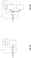
- FIGs 2A and 2B illustrate a system 4 for detecting a gas leakage for at least one combustion appliance 1, for example a gas boiler.
- the system 4 comprises a control unit 2 for determining a predicted gas consumption of the gas boiler 1 based on the operation of said gas boiler 1.
- the control unit 2 is outside the boiler 1 and is directly connected to the boiler 1 to predict the gas consumption of the boiler 1 based on the operative characteristics of said boiler 1. It is clear, however, that the control unit 2 can also be integrated in the boiler 1.
- the prediction of gas consumption can be calculated by monitoring for example the speed of a fan element or by using a flow sensor or other dedicated sensors.
- the system 4 also comprises a flow meter 3, for example a gas meter, for measuring the quantity of combustion gas to be supplied to the boiler 1.
- the gas meter 3 is located between the gas boiler 1 and a gas source (indicated with an horizontal arrow in the figure) supplying the gas boiler 1.
- Figure 2A shows an example where only one gas boiler 1 is supplied by the gas source
- figure 2B shows an example where two gas boilers 1 are supplied by the gas source.
- the gas measuring data can be acquired by a smart gas meter, in particular via a P1 port or online, or by an analogic gas meter adding a for example an optical sensor for reading the data.
- the gas meter 3 communicates with the control unit 2 and then with the gas boiler 1 so that the control unit 2 is configured to determine the presence of a gas leakage, based on the comparison between the gas measuring data and the predicted gas consumption of the boiler 1.
- a gas leakage can be detected if the gas boiler 1 and/or the other gas devices 1 are not used for longer periods of time (e.g. overnight, holidays, etc.), while the gas meter 3 measures gas consumption during this period of time. Additionally, a gas leakage can be detected if the gas meter 3 measures a significantly higher gas consumption than expected.
Landscapes
- Engineering & Computer Science (AREA)
- Chemical & Material Sciences (AREA)
- Combustion & Propulsion (AREA)
- Mechanical Engineering (AREA)
- General Engineering & Computer Science (AREA)
- Measuring Volume Flow (AREA)
- Regulation And Control Of Combustion (AREA)
Abstract
Gas leakage detection method (100) for at least one combustion appliance (1), in particular a gas boiler, the method (100) comprising: determining (S101) a predicted gas consumption of the combustion appliance (1) based on the operation of said combustion appliance (1); acquiring (S102) gas measuring data based on the measurement of the quantity of combustion gas to be supplied to the combustion appliance (1); and determining (S103) the presence of a gas leakage based on the comparison between the gas measuring data and the predicted gas consumption of the combustion appliance (1).
Description
- The invention relates to a gas detection method for a combustion appliance, in particular a gas boiler. Also, the invention relates to a computer program product executed by a computer carrying out the above method, a data processing apparatus comprising a processor for executing said computer program product, a computer readable data carrier having stored thereon the computer program product, and a data carrier signal carrying the computer program product. In addition, the invention relates to a system for detecting a gas leakage for at least one combustion appliance, in particular a gas boiler and to a combustion appliance comprising means for carrying out the method and/or said system. Also, the invention relates to a use of the computer program, or the data processing apparatus, or the system for the detection of a gas leakage for at least one combustion appliance, in particular in a gas boiler.
- Combustion appliances such as gas boilers combust gaseous fuel to heat water for domestic use and/or central heating system facilities in buildings. A gas leak in or outside the appliance, both considering the combustible fuel gas or the exhaust flue gas, can be very dangerous. For this reason, gas leakage detection systems using dedicated gas leakage sensors have been developed.
- However, the gas detection systems known in the art are not always efficient. For example, if the gas leakage sensor is located far away from the leakage, the corresponding gas detection can be extremely delayed or cannot occur at all. In addition, based on the type of the sensor, only specific types of gases can be detected and only within a predefined measurement thresholds. Accordingly, these systems are not suitable for detecting relatively small gas leakage over time and for detecting different types of gases at the same time.
- It is therefore desirable to obtain an efficient and cost-effective method for detecting a gas leakage in a combustion appliance independent from the need of having a dedicated gas leakage sensor. Also, it is desirable to obtain a method for detecting relatively small gas leakage rates over time. In addition, it is desirable to obtain a method for detecting leak rates in combustion appliances combusting different types of combustion gases.
- The object is solved by a gas leakage detection method for at least one combustion appliance, in particular a gas boiler, the method comprising:
- determining a predicted gas consumption of the combustion appliance based on the operation of said combustion appliance;
- acquiring gas measuring data based on the measurement of the quantity of combustion gas to be supplied to the combustion appliance; and
- determining the presence of a gas leakage based on the comparison between the gas measuring data and the predicted gas consumption of the combustion appliance.
- In this way, it is possible to detect a gas leakage even if no dedicated gas sensor is present or if the gas sensor is malfunctioning. Most importantly, the leakage can be promptly detected independent form the source of the leakage (e.g. inside or outside the combustion appliance). Also, it is possible to detect relatively small gas leakage rates over time, independent from a measurement threshold of an individual leakage sensor and can be detected the leakage of different types of gases. For example, the inventive method can be used to detect leak rates in an installation as a result of switching from natural gas to hydrogen.
- The measured gas can be a gas mixture that is supplied to the combustion application. The gas mixture comprises air and combustion gas. Alternatively the measured gas can correspond to the combustion gas.
- In one example, the presence of the gas leakage is determined if a consumption deviation based on the difference between the gas measuring data and the predicted gas consumption of the combustion appliance is greater than a leakage threshold, and/or if the quantity of combustion gas to be supplied to the gas consuming appliance increases over a reference period of time, when the combustion appliance is not operating. In fact, in case the measured gas is higher than the gas assumed to be consumed by the combustion appliance, it is evident that a gas leakage is present. In a similar way, a suddenly increase of the measured gas over short periods of time is a hint of a leak. Once determined the presence of a gas leakage, a detailed investigation of the combustion appliance can be carried put in order to find out the leak source.
- In another example, the method comprises determining whether the combustion gas is supplied to a single combustion appliance or to a plurality of combustion appliances. In this way, it is excluded that difference between the measured gas and the predicted gas consumption of a combustion appliance is due to the presence of another gas consuming appliance present in the heating system.
- In particular, the determination of the presence of a single combustion appliance or a plurality of combustion appliances is carried out by monitoring the gas consumption over a predefined monitoring period of time, in particular more than one day, more in particular between one day and sixty days, and/or by setting a parameter in the control unit.
- In a further example, the predicted gas consumption is determined based on the operation of a fan element, in particular the rotational velocity of the fan element, and/or based on sensor data, in particular gas flow sensor data.
- According to an example, the quantity of combustion gas to be supplied to the combustion appliance is measured using a digital flow meter or an analogic flow meter combined with a reading sensor, in particular an optical sensor.
- Advantageously, in order to constantly monitoring the gas consumption, the gas measuring data are acquired periodically, in particular every 15 minutes.
- In one example, the method can furthermore comprise the step of monitoring a gas pressure in the combustion appliance over time by a pressure sensor. If a pressure decrease over time is detected, then the combustion appliance can be turned off, and/or a gas valve can be closed, and/or an information message can be sent to a user.
- After determining the presence of a gas leakage, the method can additionally comprise: sending an alarm message to a user, and/or stopping or locking the combustion appliance. In this way, a more dangerous situation is prevented and a user (e.g. installer or technician) can be promptly informed of the leakage. Advantageously, after determining the presence of a gas leakage, the method further comprises sending information data to a terminal or to a cloud platform.
- In another example, the method can further comprise acquiring temperature data by a thermostat and combining said temperature data with the gas measuring data. In this way, it is possible to eventually predict energy labels of the combustion appliance.
- According to one aspect of the invention, a computer program product is provided. This product comprises instructions which, when the program is executed by a computer or control unit, cause the computer or the control unit to carry out the inventive method.
- In a further aspect of the invention, a data processing apparatus is provided. This data processing apparatus comprises a processor for executing the inventive computer program product. Also, a computer readable data carrier is provided, the carrier having stored thereon the inventive computer program product. In addition, data carrier signal is provided, the signal carrying the computer program product.
- According to a further aspect of the invention, a system for detecting a gas leakage for at least one combustion appliance, in particular a gas boiler, is provided. The system comprises a control unit for determining a predicted gas consumption of the combustion appliance based on the operation of said combustion appliance, and at least a flow meter for measuring the quantity of combustion gas to be supplied to the combustion appliance and generating gas measuring data, wherein the control unit is configured to determine the presence of a gas leakage, based on the comparison between the gas measuring data and the predicted gas consumption of the combustion appliance.
- In this way, a communication between the flow meter and the combustion appliance can be established through the control unit, thereby eventually realizing a smart Internet of Things system. Such a system can detect even the lowest leak rates over time, even in periods when the combustion appliance is not running. Additionally, it is possible to recommend the customer to improve the installation by sending dedicated alert messages. In particular, the system can be connected to Internet so that the control unit or the combustion appliance can send data to a cloud platform offering the possibility to combine this feature with several other features.
- According to one aspect of the invention, a combustion appliance, in particular a gas boiler, is provided, the combustion appliance comprising means for carrying out the inventive method and/or comprising the inventive system. Examples of combustion appliances can include furnaces, water heaters, boilers, direct/in-direct make-up air heaters, power/jet burners and any other residential, commercial or industrial combustion appliance.
- The combustion gas can be a natural gas, methane, ethylene, propane, butane, coal gas, biogas etc., mixtures of the same, and mixtures of the same additionally comprising hydrogen or hydrogen, in particular pure hydrogen. Pure hydrogen is present if the fuel gas has a at least 98 vol% of hydrogen. In particular, the appliance including the present system can be a gas boiler for the combustion of hydrogen gas. In this case, it is intended a fuel gas that comprises at least 20 mol%, in particular 90%, hydrogen or natural gas or mixtures thereof.
- In another aspect of the invention, the use of the inventive computer program product or of the inventive system is provided. The use is suitable for the detection of a gas leakage for at least one combustion appliance, in particular a gas boiler and more in particular a gas boiler using a fuel gas having at least 20% hydrogen or natural gas.
- In the figures, the subject-matter of the invention is schematically shown, wherein identical or similarly acting elements are usually provided with the same reference signs.
- Figure 1
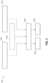
- shows a flow chart of a method for gas leakage detection according to an embodiment,
- Figure 2A
- show a schematic representation of a gas detection system according to another embodiment that has only one gas boiler,
- Figure 2B
- show a schematic representation of a gas detection system according to a further embodiment that has two gas boilers.
- With reference to
figure 1 , a flow chart describing amethod 100 for detecting a gas leakage in acombustion appliance 1 is shown. Based on the operation of thecombustion appliance 1, themethod 100 comprises a prediction of the gas consumption at step S101. This can be carried out by acontrol unit 2 of thecombustion appliance 1 shown infig. 2A and 2B . A step S102, themethod 100 comprises reading and logging gas measuring data. In particular, the quantity of combustion gas, i.e. the volume of gas, supplied to thecombustion appliance 1, is measured. This is done by the measurements of a gas meter. The gas measuring data are compared to the gas consumption prediction made by thecontrol unit 2 to determine the presence of a gas leakage at step S103. Steps S101 and 102 can be performed at the same time. - At step S106, the
method 100 can determine whether or not thecombustion appliance 1 is the only gas consumer after the gas meter. An algorithm incorporated in thecontrol unit 2 can determine if more consumers are installed by monitoring gas consumption over longer periods of time. For example, a couple of days or even months can be required to assess this information. Alternatively the installer or end user can set a parameter in thecontrol unit 2 that no other gas consumers are installed, or that other gas consumers are installed (optionally including type of products). This method step can be extremely useful in order to exclude that a deviation between the gas supplied and the gas consumed is indeed due to the presence of a plurality of gas consuming appliances connected to the same gas source. - By reading the signal from the gas meter on a frequent basis (e.g. every 10-20 minutes, in particular every 15 minutes), it is possible to determine if the gas consumption suddenly increases over shorter periods of time while the combustion appliance is not used, or if the consumption exceeds the consumption of the appliance. Accordingly, once the presence of a gas leakage is determined, at step S104 the
method 100 can send an alarm message to a user by thecontrol unit 2 that the installation should be checked. In alternative or additionally, at step S105 themethod 100 can turn off (stop or lock) thecombustion appliance 1. In this way, dangerous situations can be promptly avoided. -
Figures 2A and 2B illustrate asystem 4 for detecting a gas leakage for at least onecombustion appliance 1, for example a gas boiler. In particular, thesystem 4 comprises acontrol unit 2 for determining a predicted gas consumption of thegas boiler 1 based on the operation of saidgas boiler 1. According tofigure 2A and 2B , thecontrol unit 2 is outside theboiler 1 and is directly connected to theboiler 1 to predict the gas consumption of theboiler 1 based on the operative characteristics of saidboiler 1. It is clear, however, that thecontrol unit 2 can also be integrated in theboiler 1. The prediction of gas consumption can be calculated by monitoring for example the speed of a fan element or by using a flow sensor or other dedicated sensors. - The
system 4 also comprises aflow meter 3, for example a gas meter, for measuring the quantity of combustion gas to be supplied to theboiler 1. Thegas meter 3 is located between thegas boiler 1 and a gas source (indicated with an horizontal arrow in the figure) supplying thegas boiler 1.Figure 2A shows an example where only onegas boiler 1 is supplied by the gas source, whereasfigure 2B shows an example where twogas boilers 1 are supplied by the gas source. The gas measuring data can be acquired by a smart gas meter, in particular via a P1 port or online, or by an analogic gas meter adding a for example an optical sensor for reading the data. - It is noted that the
gas meter 3 communicates with thecontrol unit 2 and then with thegas boiler 1 so that thecontrol unit 2 is configured to determine the presence of a gas leakage, based on the comparison between the gas measuring data and the predicted gas consumption of theboiler 1. A gas leakage can be detected if thegas boiler 1 and/or theother gas devices 1 are not used for longer periods of time (e.g. overnight, holidays, etc.), while thegas meter 3 measures gas consumption during this period of time. Additionally, a gas leakage can be detected if thegas meter 3 measures a significantly higher gas consumption than expected. - Using the here described gas
leakage detection system 4, it is possible to detect low leak rates over time, thereby leading to a less environmental impact and to lower gas consumption costs for the end-user. -
- 1
- Combustion appliance
- 2
- Control unit
- 3
- Flow meter
- 4
- System
- 100
- Method
Claims (15)
- Gas leakage detection method (100) for at least one combustion appliance (1), in particular a gas boiler, the method (100) comprising:determining (S101) a predicted gas consumption of the combustion appliance (1) based on the operation of said combustion appliance (1);acquiring (S102) gas measuring data based on the measurement of the quantity of combustion gas to be supplied to the combustion appliance (1); anddetermining (S103) the presence of a gas leakage based on the comparison between the gas measuring data and the predicted gas consumption of the combustion appliance (1).
- Method (100) according to claim 1, characterized in that the presence of the gas leakage is determined if:a. a consumption deviation based on the difference between the gas measuring data and the predicted gas consumption of the combustion appliance (1) is greater than a leakage threshold; and/orb. the quantity of combustion gas to be supplied to the gas consuming appliance (1) increases over a reference period of time, when the combustion appliance (1) is not operating.
- Method (100) according to any one of claims 1 to 2, characterized in that the method (100) further comprises:
determining (S106) whether the combustion gas is supplied to a single combustion appliance (1) or to a plurality of combustion appliances (1). - Method (100) according to claim 3, characterized in that the determination of the presence of a single combustion appliance (1) or a plurality of combustion appliances (1) is carried out by:a. monitoring the gas consumption over a predefined monitoring period of time, in particular more than one day, more in particular between one day and sixty days; and/orb. setting a parameter in the control unit.
- Method (100) according to any one of claims 1 to 4, characterized in that the predicted gas consumption is determined based on:a. the operation of a fan element, in particular the rotational velocity of the fan element; and/orb. sensor data, in particular gas flow sensor data.
- Method (100) according to any one of claims 1 to 5, characterized in that,a. the quantity of combustion gas to be supplied to the combustion appliance (1) is measured using a digital flow meter or an analogic flow meter combined with a reading sensor, in particular an optical sensor; and/orb. the gas measuring data are acquired periodically, in particular every 15 minutes.
- Method (100) according to any one of claims 1 to 6, characterized in that, the method comprises monitoring a gas pressure in the combustion appliance (1) over time by a pressure sensor, wherein if a pressure decrease over time is detected:a. the combustion appliance (1) is turned off; and/orb. a gas valve is closed; and/orc. an information message is sent to a user.
- Method (100) according to any one of claims 1 to 7, characterized in that, after determining (S103) the presence of a gas leakage, the method (100) comprises:a. sending (S104) an alarm message to a user; and/orb. stopping or locking (S105) the combustion appliance (1).
- Method (100) according to any one of claims 1 to 8, characterized in that, after determining (S103) the presence of a gas leakage, the method (100) further comprises sending information data to a terminal or to a cloud platform.
- Method (100) according to any one of claims 1 to 9, characterized in that, the method (100) further comprises acquiring temperature data by a thermostat and combining said temperature data with the gas measuring data for predicting energy labels of the combustion appliance (1).
- Computer program product comprising instructions which, when the program is executed by a computer or control unit (2), cause the computer or the control unit (2) to carry out the method (100) according to one of the claims 1 to 10.
- Data processing apparatus comprising a processor for executing the computer program product of claim 11, or computer readable data carrier having stored thereon the computer program product of claim 11, or data carrier signal carrying the computer program product of claim 11.
- System (4) for detecting a gas leakage for at least one combustion appliance (1), in particular a gas boiler, the system (4) comprising:a control unit (2) for determining a predicted gas consumption of the combustion appliance (1) based on the operation of said combustion appliance (1); andat least a flow meter (3) for measuring the quantity of combustion gas to be supplied to the combustion appliance and generating gas measuring data,wherein the control unit (2) is configured to determine the presence of a gas leakage, based on the comparison between the gas measuring data and the predicted gas consumption of the combustion appliance (1).
- Combustion appliance (1), in particular a gas boiler, comprising means for carrying out the method (100) according to one of the claims 1 to 10 and/or comprising the system (4) of claim 13, wherein in particular the combustion appliance (1) uses a fuel gas having at least 20 mol% hydrogen or natural gas.
- Use of the computer program product according to claim 11 or of the system (4) according to claim 13 for the detection of a gas leakage for at least one combustion appliance (1), in particular a gas boiler and more in particular a gas boiler using a fuel gas having at least 20 mol% hydrogen or natural gas.
Priority Applications (3)
| Application Number | Priority Date | Filing Date | Title |
|---|---|---|---|
| EP22163961.0A EP4249804A1 (en) | 2022-03-24 | 2022-03-24 | Gas detection method for a gas boiler |
| PCT/EP2023/057668 WO2023180540A1 (en) | 2022-03-24 | 2023-03-24 | Gas detection method for a gas boiler |
| EP23713388.9A EP4500083A1 (en) | 2022-03-24 | 2023-03-24 | Gas detection method for a gas boiler |
Applications Claiming Priority (1)
| Application Number | Priority Date | Filing Date | Title |
|---|---|---|---|
| EP22163961.0A EP4249804A1 (en) | 2022-03-24 | 2022-03-24 | Gas detection method for a gas boiler |
Publications (1)
| Publication Number | Publication Date |
|---|---|
| EP4249804A1 true EP4249804A1 (en) | 2023-09-27 |
Family
ID=80933217
Family Applications (2)
| Application Number | Title | Priority Date | Filing Date |
|---|---|---|---|
| EP22163961.0A Withdrawn EP4249804A1 (en) | 2022-03-24 | 2022-03-24 | Gas detection method for a gas boiler |
| EP23713388.9A Pending EP4500083A1 (en) | 2022-03-24 | 2023-03-24 | Gas detection method for a gas boiler |
Family Applications After (1)
| Application Number | Title | Priority Date | Filing Date |
|---|---|---|---|
| EP23713388.9A Pending EP4500083A1 (en) | 2022-03-24 | 2023-03-24 | Gas detection method for a gas boiler |
Country Status (2)
| Country | Link |
|---|---|
| EP (2) | EP4249804A1 (en) |
| WO (1) | WO2023180540A1 (en) |
Citations (3)
| Publication number | Priority date | Publication date | Assignee | Title |
|---|---|---|---|---|
| JPS60126517A (en) * | 1983-12-13 | 1985-07-06 | Toshiba Electric Equip Corp | Gas apparatus monitoring and controlling system |
| WO2012125022A2 (en) * | 2011-03-14 | 2012-09-20 | R.P. Van Der Donk Beheer B.V. | Arrangement comprising a gas delivery control system and a central heating installation and gas delivery control method |
| EP3557132A1 (en) * | 2018-04-20 | 2019-10-23 | Electrolux Appliances Aktiebolag | Method for detecting anomalies associated with a gas appliance |
-
2022
- 2022-03-24 EP EP22163961.0A patent/EP4249804A1/en not_active Withdrawn
-
2023
- 2023-03-24 EP EP23713388.9A patent/EP4500083A1/en active Pending
- 2023-03-24 WO PCT/EP2023/057668 patent/WO2023180540A1/en not_active Ceased
Patent Citations (3)
| Publication number | Priority date | Publication date | Assignee | Title |
|---|---|---|---|---|
| JPS60126517A (en) * | 1983-12-13 | 1985-07-06 | Toshiba Electric Equip Corp | Gas apparatus monitoring and controlling system |
| WO2012125022A2 (en) * | 2011-03-14 | 2012-09-20 | R.P. Van Der Donk Beheer B.V. | Arrangement comprising a gas delivery control system and a central heating installation and gas delivery control method |
| EP3557132A1 (en) * | 2018-04-20 | 2019-10-23 | Electrolux Appliances Aktiebolag | Method for detecting anomalies associated with a gas appliance |
Also Published As
| Publication number | Publication date |
|---|---|
| WO2023180540A1 (en) | 2023-09-28 |
| EP4500083A1 (en) | 2025-02-05 |
Similar Documents
| Publication | Publication Date | Title |
|---|---|---|
| US9217654B2 (en) | Submetering hydrocarbon fueled water heaters with energy manager systems | |
| CN103518124A (en) | Fluid leakage detection system | |
| EP3874202A1 (en) | Flame analytics system | |
| JP4558168B2 (en) | Gas metering monitoring system | |
| CN102007343A (en) | Gas shut-off device and alarm-compatible system meter | |
| US10031501B2 (en) | Apparatus and method for detecting degradation in climate control system performance | |
| KR102176143B1 (en) | Boiler safety management device and boiler safety management system including the same | |
| WO2023180540A1 (en) | Gas detection method for a gas boiler | |
| JP2009075015A (en) | Flow rate measuring device and flow rate measuring method | |
| CN103339480A (en) | Flow measurement device | |
| US20060275719A1 (en) | Warm air furnace baselining and diagnostic enhancements using rewritable non-volatile memory | |
| JP6177547B2 (en) | Alarm system | |
| JP2006053073A (en) | Gas flow state recognizer | |
| JP2022015555A (en) | Gas leakage inspection system | |
| EP4253866A1 (en) | Sensor for water heaters | |
| WO2016135494A1 (en) | A method of monitoring the usage of a boiler, a boiler and a boiler usage sensor | |
| KR100717119B1 (en) | Detection method of wind pressure sensor abnormality in air proportional control boiler using wind pressure sensor | |
| JP7289105B2 (en) | Gas meter and gas meter management system | |
| JP2009128068A (en) | Gas leakage detection system | |
| EP1980789A2 (en) | Method for monitoring and regulating the combustion of a gas boiler, and boiler for the embodiment of said method | |
| JP6767617B2 (en) | Gas meter system | |
| JP2004295296A (en) | Utility consumption equipment and recognition device for operation of utility consumption equipment | |
| JP5334283B2 (en) | Instrument monitoring device | |
| GB2442607A (en) | Monitoring fuel energy consumption from analysis of electricity usage | |
| WO2012137473A1 (en) | Flow rate measurement device |
Legal Events
| Date | Code | Title | Description |
|---|---|---|---|
| PUAI | Public reference made under article 153(3) epc to a published international application that has entered the european phase |
Free format text: ORIGINAL CODE: 0009012 |
|
| STAA | Information on the status of an ep patent application or granted ep patent |
Free format text: STATUS: THE APPLICATION HAS BEEN PUBLISHED |
|
| AK | Designated contracting states |
Kind code of ref document: A1 Designated state(s): AL AT BE BG CH CY CZ DE DK EE ES FI FR GB GR HR HU IE IS IT LI LT LU LV MC MK MT NL NO PL PT RO RS SE SI SK SM TR |
|
| STAA | Information on the status of an ep patent application or granted ep patent |
Free format text: STATUS: THE APPLICATION IS DEEMED TO BE WITHDRAWN |
|
| 18D | Application deemed to be withdrawn |
Effective date: 20240328 |