EP4249642A1 - Electrolysis method and arrangement - Google Patents
Electrolysis method and arrangement Download PDFInfo
- Publication number
- EP4249642A1 EP4249642A1 EP22163339.9A EP22163339A EP4249642A1 EP 4249642 A1 EP4249642 A1 EP 4249642A1 EP 22163339 A EP22163339 A EP 22163339A EP 4249642 A1 EP4249642 A1 EP 4249642A1
- Authority
- EP
- European Patent Office
- Prior art keywords
- electrolysis
- stack
- cur
- flow rate
- electrolysis stack
- Prior art date
- Legal status (The legal status is an assumption and is not a legal conclusion. Google has not performed a legal analysis and makes no representation as to the accuracy of the status listed.)
- Pending
Links
- 238000005868 electrolysis reaction Methods 0.000 title claims abstract description 292
- 239000002826 coolant Substances 0.000 claims abstract description 60
- 238000000034 method Methods 0.000 claims abstract description 46
- 238000009434 installation Methods 0.000 claims description 39
- 238000001816 cooling Methods 0.000 claims description 18
- 238000005259 measurement Methods 0.000 claims description 8
- XLYOFNOQVPJJNP-UHFFFAOYSA-N water Substances O XLYOFNOQVPJJNP-UHFFFAOYSA-N 0.000 description 25
- 229910001868 water Inorganic materials 0.000 description 25
- 229910052739 hydrogen Inorganic materials 0.000 description 6
- 239000001257 hydrogen Substances 0.000 description 6
- 238000011144 upstream manufacturing Methods 0.000 description 6
- UFHFLCQGNIYNRP-UHFFFAOYSA-N Hydrogen Chemical compound [H][H] UFHFLCQGNIYNRP-UHFFFAOYSA-N 0.000 description 5
- QVGXLLKOCUKJST-UHFFFAOYSA-N atomic oxygen Chemical compound [O] QVGXLLKOCUKJST-UHFFFAOYSA-N 0.000 description 5
- 229910052760 oxygen Inorganic materials 0.000 description 5
- 239000001301 oxygen Substances 0.000 description 5
- 238000010438 heat treatment Methods 0.000 description 4
- 230000000694 effects Effects 0.000 description 3
- 239000007788 liquid Substances 0.000 description 3
- 238000004088 simulation Methods 0.000 description 2
- 239000003011 anion exchange membrane Substances 0.000 description 1
- 238000009529 body temperature measurement Methods 0.000 description 1
- 230000001419 dependent effect Effects 0.000 description 1
- 150000002431 hydrogen Chemical class 0.000 description 1
- 238000004519 manufacturing process Methods 0.000 description 1
- 150000003839 salts Chemical class 0.000 description 1
Images

Classifications
-
- C—CHEMISTRY; METALLURGY
- C25—ELECTROLYTIC OR ELECTROPHORETIC PROCESSES; APPARATUS THEREFOR
- C25B—ELECTROLYTIC OR ELECTROPHORETIC PROCESSES FOR THE PRODUCTION OF COMPOUNDS OR NON-METALS; APPARATUS THEREFOR
- C25B15/00—Operating or servicing cells
- C25B15/02—Process control or regulation
- C25B15/021—Process control or regulation of heating or cooling
-
- C—CHEMISTRY; METALLURGY
- C25—ELECTROLYTIC OR ELECTROPHORETIC PROCESSES; APPARATUS THEREFOR
- C25B—ELECTROLYTIC OR ELECTROPHORETIC PROCESSES FOR THE PRODUCTION OF COMPOUNDS OR NON-METALS; APPARATUS THEREFOR
- C25B15/00—Operating or servicing cells
- C25B15/02—Process control or regulation
- C25B15/023—Measuring, analysing or testing during electrolytic production
Definitions
- the invention is directed to a method for performing an electrolysis as well as to a respective arrangement.
- Electrolysis is preferably performed using renewable energies.
- renewable energies such as solar and wind power fluctuates.
- the object of the invention is to improve the prior art so that the temperature of an electrolysis process can be controlled particularly quickly and accurately.
- a method for performing an electrolysis with an electrolysis stack wherein an electrolysis medium is used for the electrolysis that is cooled by means of a cooling medium provided at a flow rate F, wherein the flow rate F of the cooling medium is set to a value depending on a current value I cur of a current density of the electrolysis stack and a current value V cur of a cell voltage of the electrolysis stack.
- the electrolysis method can be used for electrolysis of any electrolysis medium.
- the electrolysis medium is liquid, in particular water.
- the electrolysis medium can be water only.
- the electrolysis medium may be water that contains dissolved salts such as KOH for alkaline electrolysis or electrolysis using anion exchange membrane cells.
- the electrolysis products are preferably gaseous. In the case of water, hydrogen and oxygen can be obtained as the electrolysis products.
- the electrolysis method is intended to be used for an industrial scale electrolysis. For example, it is preferred that at least one of the electrolysis products is obtained at a rate of 250 to 1500 Nm 3 per hour per electrolysis stack. This applies, in particular, to the production of hydrogen in the case of water electrolysis.
- the electrolysis is preferably performed in an automated way.
- the electrolysis method is performed using an electrolysis stack. That is, it is possible that the electrolysis method can be performed with one or more electrolysis stacks. Preferably, the electrolysis stacks each have a maximum rated DC power consumption in the range of 1 to 20 MW, in particular in the range of 3 to 10 MW.
- the described electrolysis method is preferably used for industrial scale electrolysis. In particular, this is to be understood in contrast to experimental setups on a laboratory scale.
- the industrial scale can be quantified in terms of the maximum rated DC power consumption of the electrolysis stack(s).
- the maximum rated DC power consumption is what is commonly used to describe electrolysis stacks. For example, a "5 MW electrolysis stack" has a maximum rated DC power consumption of 5 MW.
- the electrolysis is performed with the electrolysis medium within the electrolysis stack.
- the electrolysis medium can be supplied to the electrolysis stack continuously, for example via a feed installation.
- the electrolysis medium can be circulated by means of the feed installation, in particular through the electrolysis stack and further elements such as a separator and/or a heat exchanger. That is, the electrolysis medium can enter the electrolysis stack, where the electrolysis is performed. Thereby, the electrolysis medium is converted into the electrolysis products.
- the remaining electrolysis medium can be guided out of the electrolysis stack. This remaining electrolysis medium is mixed with the electrolysis products.
- the electrolysis medium After having separated the electrolysis products from the electrolysis medium, for example within a separator, the electrolysis medium can be fed back to the electrolysis stack. To this end, the circle is closed. This is supposed to be understood such that there is a closed loop path, along which the electrolysis medium can flow, which involves the electrolysis stack. However, the electrolysis medium is continuously converted into the electrolysis products, such that there is a loss of electrolysis medium.
- the feed installation preferably comprises an inlet, via which new electrolysis medium can be introduced into the circulation. That is, a certain amount of the electrolysis medium introduced into the circulation via the inlet can pass the electrolysis stack one or several times, until this particular amount of the electrolysis medium is converted into the electrolysis products.
- the feed installation is configured as a single feed line.
- the feed installation can comprise multiple independent feed lines.
- the feed installation comprises one or more separators.
- the feed installation can be part of a circuit, via which the electrolysis medium can be circulated.
- the electrolysis medium together with an anode product of the electrolysis can be guided from the anode of the electrolysis stack to an anode separator, where the anode product can be separated from the electrolysis medium.
- the electrolysis medium together with a cathode product of the electrolysis can be guided from the cathode of the electrolysis stack to a cathode separator, where the cathode product can be separated from the electrolysis medium.
- the electrolysis medium can be guided back to the electrolysis stack via a feed line that, together with the separators, is part of the feed installation.
- the feed installation is configured as a feed line that has two branches, one of which being connected to an anode space or anode spaces of the electrolysis stack and the other one being connected to a cathode space or cathode spaces of the electrolysis stack.
- the feed installation comprises multiple feed line branches that merge into a single feed line. For example, a first of these branches can be connected to the anode separator and a second of these branches can be connected to the cathode separator. Downstream of where the branches merge the feed line can be connected to the electrolysis stack as a single line or as two branches.
- the electrolysis is performed at a temperature in the range of 50 to 120°C, in particular of 90 °C.
- this temperature can be controlled indirectly.
- the cooling medium is provided.
- the electrolysis medium is circulated through the electrolysis stack and a heat exchanger, wherein the electrolysis medium is cooled in the heat exchanger by means of a cooling medium provided to the heat exchanger at the flow rate F.
- the described method is also applicable in case the electrolysis medium is provided in the electrolysis stack in a stationary manner. In that case the electrolysis medium can be cooled by the cooling medium within the electrolysis stack. The cooling medium is fed at a flow rate such that the heating caused by the electrolysis and the cooling caused by the cooling medium result in a desired temperature of the electrolysis medium within the electrolysis stack.
- the electrolysis medium can be cooled by the cooling medium at any point upstream or within the electrolysis stack. This includes that the electrolysis medium can be cooled by the cooling medium at any point of the feed installation. It is sufficient that the electrolysis medium is cooled by the cooling medium at a point where the cooling impacts the electrolysis. That is, the cooling is performed prior or during the electrolysis.
- the feed installation can have an anode feed and a cathode feed that are separate from each other. In that case, the electrolysis medium can be cooled by the cooling medium in the anode feed and/or in the cathode feed. That is, it is sufficient to cool only the electrolysis medium that is fed to the anodes or to cool only the electrolysis medium that is fed to the cathodes.
- the feed installation can have a joint feed for both anodes and cathodes.
- the method can be applied to a single electrolysis stack.
- the method can be applied to multiple electrolysis stacks.
- the electrolysis medium can be fed to the electrolysis stacks using separate feed installations for the electrolysis stacks or using a common feed installation for all electrolysis stacks.
- each electrolysis stack can be treated like the single electrolysis stack described exemplarily herein.
- the described method can be performed using parameters of one of the electrolysis stacks. To this end, this electrolysis stack is assumed to be representative of the other electrolysis stacks. Alternatively, the parameters of all the electrolysis stacks can be taken into account.
- the common feed installation can have, for example, a single heat exchanger via which the electrolysis medium can be cooled prior to being fed to the electrolysis stacks.
- the flow rate F of the cooling medium is the flow rate at which the cooling medium is supplied to this heat exchanger.
- the electrolysis medium is preferably circulated through the electrolysis stack and a heat exchanger.
- the electrolysis medium can be cooled within the heat exchanger. This occurs upstream of the electrolysis stack to the end that the electrolysis medium is guided from the heat exchanger back to the electrolysis stack.
- the heat exchanger is integrated into a feed line that is part of the feed installation.
- the heat exchanger is integrated into a feed line that extends from an anode separator and/or from a cathode separator to the electrolysis stack. That is, the heat exchanger is preferably arranged between the anode separator and/or the cathode separator on the one hand and the electrolysis stack on the other hand.
- the heat exchanger is arranged within the anode separator and/or the cathode separator. There can be more than one heat exchanger. For example, separate feed lines for the anode and cathode can have a respective heat exchanger.
- the cooling medium is provided to the heat exchanger at a flow rate F.
- the flow rate F of the cooling medium has an influence on the temperature of the electrolysis medium.
- the temperature of the electrolysis medium downstream of the heat exchanger can also depend on the temperature of the cooling medium and on the flow rate at which the electrolysis medium flows through the heat exchanger. The best results are thus obtained in the preferred case that the temperature of the cooling medium is constant and the electrolysis medium flows at a constant flow rate through the heat exchanger.
- acceptable results can also be obtained if these conditions are not met.
- a minor deviation in cooling medium temperature and/or in flow rate of the electrolysis medium will only have a minor influence on the result.
- the temperature of the cooling medium does not fluctuate by more than 20 °C, in particular by not more than 10 °C, and/or that the electrolysis medium flows through the heat exchanger at a flow rate that does not fluctuate by more than 20 % of the average flow rate, in particular not by more than 10 % of the average flow rate. Even if these preferred conditions are not met, the described method can outperform prior art teachings.
- the temperature of the electrolysis medium downstream of the heat exchanger in general depends on the temperature of the electrolysis medium upstream of the heat exchanger.
- the temperature of electrolysis medium upstream of the heat exchanger results from the temperature of the electrolysis medium downstream of the heat exchanger and from the heating caused by the electrolysis.
- This heating depends on the electrical energy supplied to the electrolysis stack.
- this heating can be predicted from the current density of the electrolysis stack and the cell voltage of the electrolysis stack.
- the flow rate F of the cooling medium is set to a value depending on a current value I cur of the current density of the electrolysis stack and a current value V cur of the cell voltage of the electrolysis stack.
- the current value I cur of the current density of the electrolysis stack and the current value V cur of the cell voltage of the electrolysis stack can be determined by measurement. Alternatively, these values can be extracted from a control unit, which supplies electrical energy to the electrolysis stack at these values.
- the current density is the electrical current applied to the electrolysis stack divided by the cell area of the electrolysis cells of the electrolysis sack.
- the letter I is used to indicate the current density. It is also common to use the letter I for the current and the letter J for the current density. Instead of the current density, the current applied to the electrolysis stack could be used as well. This is because the cell area is a constant.
- the cell voltage of the electrolysis stack is the voltage applied to each of the electrolysis cells of the electrolysis stack. For example, if the electrolysis cells of the electrolysis stack are electrically in series, the voltage applied to the electrolysis stack is the sum of the respective cell voltages applied to the electrolysis cells of the electrolysis stack. The cell voltage is preferably the same for all electrolysis cells.
- the cell voltage can be obtained by dividing the voltage applied to the electrolysis stack by the number of electrolysis cells the electrolysis stack has. This can even be done in case the electrolysis cells of the electrolysis stack are not identical to each other. In that case, an average cell voltage is obtained. It is generally preferred to use the average cell voltage as the cell voltage in the described method.
- the letter V is used for the cell voltage.
- the described method is particularly fast. In particular, fluctuations in the supply of the electrical energy can be reacted to particularly quickly. To this end, the described method is particularly suitable to be used with renewable energies. It is thus preferred that electrical energy is supplied to the electrolysis stack from a renewable energy source.
- the renewable energy source can be a solar power plant or a wind turbine.
- the described method is also applicable with any other energy source.
- the quick response according to the invention can be achieved in that the current density and the cell voltage of the electrolysis stack are used for the temperature control.
- a change in the supply of the electrical energy is expressed in that the current density and the cell voltage of the electrolysis stack change. To this end, the change in the supply of the electrical energy can be detected as such and the flow rate of the cooling medium can be adapted accordingly.
- the temperature control was based on a temperature measurement, a change in the supply of the electrical energy could only be detected once the measured temperature changes. However, the temperature changes in such a case only with a delay. To this end, the temperature of the electrolysis process can be controlled with the described method particularly quickly. This results in a particularly accurate control.
- the flow rate F is set using a feedforward control process.
- the flow rate of the cooling medium was controlled based on a measurement of the temperature, this could be referred to as a feedback control process. This is because the result (i.e. the temperature) is observed and fed back to where a manipulation is possible (i.e. the cooling using a cooling medium at a certain flow rate).
- the described method constitutes a feedforward control process.
- the cause for a potential change i.e. the supply of electrical energy that potentially could change the temperature
- a manipulation i.e. in the cooling using a cooling medium at a certain flow rate
- a reference value F ref of the flow rate of the cooling medium is provided.
- the reference conditions are defined, in particular, in that therein the current density of the electrolysis stack has a reference value I ref and the cell voltage of the electrolysis stack has a reference value V ref .
- Step a) can be considered a calibration step.
- the reference conditions can be chosen arbitrarily.
- the reference conditions can be set to the current conditions at the time step a) is supposed to be carried out. That is, in order to perform step a), the current value I cur of the current density of the electrolysis stack and the current value V cur of the cell voltage of the electrolysis stack can be determined, for example by measurement or by reading from a control unit, and the reference value I ref of the current density of the electrolysis stack and the reference value V ref of the cell voltage of the electrolysis stack can be defined to be equal to these values.
- the reference value F ref of the flow rate of the cooling medium can be provided in that it is determined which flow rate is desired under the reference conditions. This can be done experimentally. Therein, the reference value F ref can be set to a value that provides a satisfactory result.
- the reference values F ref , I ref and V ref can be determined theoretically.
- the reference values I ref and V ref can be set to a arbitrary values and it can be calculated which flow rate of the cooling medium would be desired for these values.
- the reference values F ref , I ref and V ref can be determined prior to the beginning of the described method.
- the current value I cur of the current density of the electrolysis stack and the current value V cur of the cell voltage of the electrolysis stack deviate as little as possible from the respective reference values I ref and V ref .
- the reference value I ref of the current density of the electrolysis stack and the reference value V ref of the cell voltage of the electrolysis stack are defined to be respective average values of the current value I cur of the current density of the electrolysis stack and the current value V cur of the cell voltage of the electrolysis stack, respectively, taken over a period of time.
- the period of time is preferably, at least an hour, in particular at least a day or even at least a week.
- step b) the current value I cur of the current density of the electrolysis stack and the current value V cur of the cell voltage of the electrolysis stack are determined. This can be done by measurement or by reading from a control unit. Also, this can be done in that the respective values are calculated from other parameters that are measured or read from the control unit. It is sufficient that after step b) a value representing the current value I cur of the current density of the electrolysis stack and a value representing the current value V cur of the cell voltage of the electrolysis stack are known. For example, instead of the actual current value I cur of the current density of the electrolysis stack and the actual current value V cur of the cell voltage of the electrolysis, electrical signals could be used that represent the respective value.
- step c) the flow rate F of the cooling medium is set. This means that the actual flow rate of the cooling medium is affected, which results in a respective cooling effect on the electrolysis medium.
- the flow rate F is set to a value that depends on the reference values F ref , I ref and V ref as well as on the current values I cur and V cur .
- the current values I cur and V cur can be compared with the respective reference value I ref and V ref . If there is no deviation, the flow rate F can be simply set to the reference value F ref . If there is a deviation, the flow rate F can be set to a value that deviates from the reference value F ref accordingly.
- the value to which the flow rate F of the cooling medium is set in step c) further depends on
- thermoneutral cell voltage V th is the voltage drop across each of the electrolysis cells of the electrolysis stack that is sufficient not only to drive the electrolysis reaction, but to also provide heat so as to maintain a constant temperature. It was found that taking the thermoneutral cell voltage V th into account can improve the accuracy of the described method.
- the value to which the flow rate F of the cooling medium is set further depends on a feedback correction ⁇ F FB .
- the flow rate F of the cooling medium can be set to a value that is the sum of the feedback correction ⁇ F FB and a contribution depending on the current value I cur of the current density of the electrolysis stack and the current value V cur of the cell voltage of the electrolysis stack.
- the latter can be referred to as a feedforward value F FF .
- F F FF I cur V cur + ⁇ F FB .
- F FF ( I cur , V cur ) indicates that F FF depends on I cur and V cur .
- a feedback correction ⁇ F FB can be taken into account in any other embodiment as well.
- the feedback correction ⁇ F FB is initially set to be equal to zero.
- the flow rate F is than set to F FF ( I cur , V cur ).
- F FF I cur , V cur
- By measuring the temperature it can be checked whether or not the result obtained thereby is satisfying, for example by comparing the measured temperature with a temperature set point. In case the measured temperature equals the temperature set point, ⁇ F FB remains zero. If the supply of electrical energy changes suddenly, for example in the case of a renewable energy source, this can be compensated for because F FF ( I cur , V cur ) changes immediately. Ideally, this compensation is as accurate as that the temperature remains at the set point so that ⁇ F FB remains zero.
- the current value I cur of the current density of the electrolysis stack is determined by measurement and/or the current value V cur of the cell voltage of the electrolysis stack is determined by measurement.
- an arrangement for performing an electrolysis that comprises:
- the advantages and features of the method are transferrable to the arrangement, and vice versa.
- the method is preferably performed using the arrangement.
- the cooling installation can be configured for providing the cooling medium for the electrolysis in that the cooling installation is configured for providing the cooling medium to a heat exchanger of a feed installation, wherein the heat exchanger is arranged upstream of the electrolysis stack.
- the cooling installation can be configured for providing the cooling medium to the electrolysis stack.
- Fig. 1 shows an arrangement 2 with an electrolysis stack 1 configured for the electrolysis of water.
- the electrolysis stack 1 is connected to a feed installation 11, via which water can be fed to the electrolysis stack 1 as an electrolysis medium.
- the feed installation 11 is realized as a single feed that provides the water to both an anode and a cathode space of the electrolysis stack 1.
- an electrolysis can be performed with the water.
- the water remaining in the anode space can be guided together with the anode product, i.e. oxygen, from the electrolysis stack 1 to an anode separator 5.
- the gaseous oxygen can be extracted via an oxygen outlet 8 and the liquid water can be fed back to the electrolysis stack 1.
- new water can be introduced into the anode separator 5 via a water feed 7. That is, the feed installation 11 comprises the anode separator 5, the water feed 7 and the conduit from the electrolysis stack 1 to the anode separator 5 as well as the conduit from the anode separator 5 back to the electrolysis stack 1.
- the water remaining in the cathode space can be guided together with the cathode product, i.e. hydrogen, from the electrolysis stack 1 to a cathode separator 6.
- the cathode separator 6 From the cathode separator 6 the gaseous hydrogen can be extracted via a hydrogen outlet 9 and the liquid water can be extracted via a water outlet 12.
- a heat exchanger 10 is provided that is connected to a cooling installation 3.
- the cooling installation 3 is configured for providing a cooling medium for the electrolysis at a flow rate F.
- the water coming from the electrolysis stack 1 is cooled before it is fed back, via the anode separator 5, to the electrolysis stack 1. Since the water is circled back to the electrolysis stack 1, the water is cooled before being used in the electrolysis (again).
- the arrangement comprises a control unit that is electrically connected to the electrolysis stack 1 and to the cooling installation 3.
- the control unit is configured for controlling the arrangement 2 so as to perform an electrolysis using a method, in which the water used for the electrolysis is cooled by means of the cooling medium provided at a flow rate F, wherein the flow rate F of the cooling medium is set to a value depending on a current value I cur of a current density of the electrolysis stack 1 and a current value V cur of a cell voltage of the electrolysis stack 1.
- the feedforward term is obtained in a feedforward control installation 4, which is part of the control unit. Therefore, the feedforward control installation 4 can receive the values I cur and V cur from the electrolysis stack 1 as indicated by two dotted lines.
- the further parameters of the feedforward term F FF can be stored in a storage of the feedforward control installation 4.
- the feedback correction ⁇ F FB can be obtained with a temperature controller TC, which is also part of the control unit.
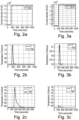
- Fig. 2a to 2c show data simulated for a conventional electrolysis arrangement (which is not shown in the figures).
- the conventional electrolysis arrangement has a single electrolysis stack with a heat exchanger and common separators that are placed horizontally. The temperature is controlled by means of a conventional PID control.
- Fig. 2a illustrates the current density applied to the electrolysis stack of the conventional electrolysis arrangement over the time. It can be seen that a jump in the current density occurs shortly before 200 s. This is supposed to simulate a sudden change in the supply of electric energy to the electrolysis stack, for example in case a renewable energy source is used.
- Fig. 2b and 2c show simulated data that illustrate how the conventional electrolysis arrangement reacts to the jump in the current density shown in Fig. 2a .
- the temperature is shown over the time.
- Fig. 2b refers to the start of operation and Fig. 2c to a later stage, where the electrolysis stack has degraded by 20 %. It can be seen that the jump in the current density results in a jump in the temperature by about 9 °C ( Fig. 2b ) and 13 °C ( Fig. 2c ), respectively.
- Fig. 3a to 3c show data simulated for the arrangement 2 of Fig. 1 . As can be seen from Fig. 3a , the same jump in the current density is simulated.
- Fig. 3b and 3c show simulated data that illustrate how the arrangement 2 of Fig. 1 reacts to the jump in the current density.
- the temperature is shown over the time similar to Fig. 2b and 2c.
- Fig. 3b refers to the start of operation and Fig. 3c to a later stage, where the electrolysis stack has degraded by 20 %. It can be seen that the jump in the current density results in a jump in the temperature by about 3.5 °C ( Fig. 3b) and 2 °C ( Fig. 3c ), respectively.
- the arrangement 2 of Fig. 1 addressed in Fig. 3a to 3c outperforms the conventional arrangement addressed in Fig. 2a to 2c .
- Fig. 3a to 3c refer to a case with feedback correction ⁇ F FB the same results could be obtained for various situations without feedback correction ⁇ F FB , for example in case external conditions remain unchanged. This is particularly true because the effect of the feedback correction ⁇ F FB is comparatively slow.
Landscapes
- Chemical & Material Sciences (AREA)
- Engineering & Computer Science (AREA)
- Automation & Control Theory (AREA)
- Chemical Kinetics & Catalysis (AREA)
- Electrochemistry (AREA)
- Materials Engineering (AREA)
- Metallurgy (AREA)
- Organic Chemistry (AREA)
- Analytical Chemistry (AREA)
- Electrolytic Production Of Non-Metals, Compounds, Apparatuses Therefor (AREA)
Abstract
Description
- The invention is directed to a method for performing an electrolysis as well as to a respective arrangement.
- In known systems for the electrolysis of water, stacks of electrolysis cells are used that are supposed to be operated at a particular temperature. If the actual temperature deviates significantly from a temperature setting, the efficiency is reduced or the stacks may be damaged. Since the electrolysis in general generates heat, usually the electrolysis stack requires cooling in order to maintain the desired temperature.
- It is known to control the temperature in that the temperature is measured and compared to a set point. In case the measured value deviates from the set point, a flow rate of a cooling medium is adapted. However, such a control loop is comparatively slow. This is particularly due to the fact that a change in the cooling medium flow rate will affect the temperature only with a delay. Also, such a temperature control is inaccurate.
- Electrolysis is preferably performed using renewable energies. However, the availability of renewable energies such as solar and wind power fluctuates. Hence, it is desired that electrolysis systems are able to handle a fluctuating supply of electric energy. In particular to this end it is desired to have a temperature control that can react quickly to a change in the supply of electrical energy.
- The object of the invention is to improve the prior art so that the temperature of an electrolysis process can be controlled particularly quickly and accurately.
- The object is solved with the method and the arrangement according to the independent claims. Advantageous refinements are presented in the dependent claims. The features described in the claims and in the description can be combined with each other in any technologically reasonable manner.
- According to the invention a method for performing an electrolysis with an electrolysis stack is presented, wherein an electrolysis medium is used for the electrolysis that is cooled by means of a cooling medium provided at a flow rate F, wherein the flow rate F of the cooling medium is set to a value depending on a current value Icur of a current density of the electrolysis stack and a current value Vcur of a cell voltage of the electrolysis stack.
- The electrolysis method can be used for electrolysis of any electrolysis medium. Preferably, the electrolysis medium is liquid, in particular water. In particular, the electrolysis medium can be water only. Alternatively, the electrolysis medium may be water that contains dissolved salts such as KOH for alkaline electrolysis or electrolysis using anion exchange membrane cells. The electrolysis products are preferably gaseous. In the case of water, hydrogen and oxygen can be obtained as the electrolysis products. The electrolysis method is intended to be used for an industrial scale electrolysis. For example, it is preferred that at least one of the electrolysis products is obtained at a rate of 250 to 1500 Nm3 per hour per electrolysis stack. This applies, in particular, to the production of hydrogen in the case of water electrolysis. The electrolysis is preferably performed in an automated way.
- The electrolysis method is performed using an electrolysis stack. That is, it is possible that the electrolysis method can be performed with one or more electrolysis stacks. Preferably, the electrolysis stacks each have a maximum rated DC power consumption in the range of 1 to 20 MW, in particular in the range of 3 to 10 MW. The described electrolysis method is preferably used for industrial scale electrolysis. In particular, this is to be understood in contrast to experimental setups on a laboratory scale. The industrial scale can be quantified in terms of the maximum rated DC power consumption of the electrolysis stack(s). The maximum rated DC power consumption is what is commonly used to describe electrolysis stacks. For example, a "5 MW electrolysis stack" has a maximum rated DC power consumption of 5 MW.
- The electrolysis is performed with the electrolysis medium within the electrolysis stack. The electrolysis medium can be supplied to the electrolysis stack continuously, for example via a feed installation. In particular, the electrolysis medium can be circulated by means of the feed installation, in particular through the electrolysis stack and further elements such as a separator and/or a heat exchanger. That is, the electrolysis medium can enter the electrolysis stack, where the electrolysis is performed. Thereby, the electrolysis medium is converted into the electrolysis products. However, usually not the entire electrolysis medium present within the electrolysis stack reacts within the electrolysis stack. The remaining electrolysis medium can be guided out of the electrolysis stack. This remaining electrolysis medium is mixed with the electrolysis products. After having separated the electrolysis products from the electrolysis medium, for example within a separator, the electrolysis medium can be fed back to the electrolysis stack. To this end, the circle is closed. This is supposed to be understood such that there is a closed loop path, along which the electrolysis medium can flow, which involves the electrolysis stack. However, the electrolysis medium is continuously converted into the electrolysis products, such that there is a loss of electrolysis medium. In order to compensate for such losses and for potential other losses, the feed installation preferably comprises an inlet, via which new electrolysis medium can be introduced into the circulation. That is, a certain amount of the electrolysis medium introduced into the circulation via the inlet can pass the electrolysis stack one or several times, until this particular amount of the electrolysis medium is converted into the electrolysis products.
- In one preferred embodiment the feed installation is configured as a single feed line. Alternatively, the feed installation can comprise multiple independent feed lines. Also, it is preferred that the feed installation comprises one or more separators. The feed installation can be part of a circuit, via which the electrolysis medium can be circulated. For example, the electrolysis medium together with an anode product of the electrolysis can be guided from the anode of the electrolysis stack to an anode separator, where the anode product can be separated from the electrolysis medium. The electrolysis medium together with a cathode product of the electrolysis can be guided from the cathode of the electrolysis stack to a cathode separator, where the cathode product can be separated from the electrolysis medium. From the separators the electrolysis medium can be guided back to the electrolysis stack via a feed line that, together with the separators, is part of the feed installation. In a further preferred embodiment the feed installation is configured as a feed line that has two branches, one of which being connected to an anode space or anode spaces of the electrolysis stack and the other one being connected to a cathode space or cathode spaces of the electrolysis stack. It is also possible that the feed installation comprises multiple feed line branches that merge into a single feed line. For example, a first of these branches can be connected to the anode separator and a second of these branches can be connected to the cathode separator. Downstream of where the branches merge the feed line can be connected to the electrolysis stack as a single line or as two branches.
- It is preferred that the electrolysis is performed at a temperature in the range of 50 to 120°C, in particular of 90 °C. By means of the described method, this temperature can be controlled indirectly. To this end, the cooling medium is provided.
- In a preferred embodiment of the method, the electrolysis medium is circulated through the electrolysis stack and a heat exchanger, wherein the electrolysis medium is cooled in the heat exchanger by means of a cooling medium provided to the heat exchanger at the flow rate F. However, although it is preferred that the electrolysis medium is circulated, the described method is also applicable in case the electrolysis medium is provided in the electrolysis stack in a stationary manner. In that case the electrolysis medium can be cooled by the cooling medium within the electrolysis stack. The cooling medium is fed at a flow rate such that the heating caused by the electrolysis and the cooling caused by the cooling medium result in a desired temperature of the electrolysis medium within the electrolysis stack.
- In general, the electrolysis medium can be cooled by the cooling medium at any point upstream or within the electrolysis stack. This includes that the electrolysis medium can be cooled by the cooling medium at any point of the feed installation. It is sufficient that the electrolysis medium is cooled by the cooling medium at a point where the cooling impacts the electrolysis. That is, the cooling is performed prior or during the electrolysis. The feed installation can have an anode feed and a cathode feed that are separate from each other. In that case, the electrolysis medium can be cooled by the cooling medium in the anode feed and/or in the cathode feed. That is, it is sufficient to cool only the electrolysis medium that is fed to the anodes or to cool only the electrolysis medium that is fed to the cathodes. Also, the feed installation can have a joint feed for both anodes and cathodes.
- The method can be applied to a single electrolysis stack. Alternatively, the method can be applied to multiple electrolysis stacks. In the latter case, the electrolysis medium can be fed to the electrolysis stacks using separate feed installations for the electrolysis stacks or using a common feed installation for all electrolysis stacks. In the case of separate feed installations, each electrolysis stack can be treated like the single electrolysis stack described exemplarily herein. In the case of a common feed installation the described method can be performed using parameters of one of the electrolysis stacks. To this end, this electrolysis stack is assumed to be representative of the other electrolysis stacks. Alternatively, the parameters of all the electrolysis stacks can be taken into account. For example, as the current value Icur of the current density of the electrolysis stack a mean value of the current values Icur of the current density of the electrolysis stacks can be used and as the a current value Vcur of the cell voltage of the electrolysis stack a mean value of the current values Vcur of the cell voltages of the electrolysis stacks can be used. The common feed installation can have, for example, a single heat exchanger via which the electrolysis medium can be cooled prior to being fed to the electrolysis stacks. In that case the flow rate F of the cooling medium is the flow rate at which the cooling medium is supplied to this heat exchanger.
- In the case the electrolysis medium is circulated, the electrolysis medium is preferably circulated through the electrolysis stack and a heat exchanger. Therein, the electrolysis medium can be cooled within the heat exchanger. This occurs upstream of the electrolysis stack to the end that the electrolysis medium is guided from the heat exchanger back to the electrolysis stack.
- It is preferred that the heat exchanger is integrated into a feed line that is part of the feed installation. In particular, it is preferred that the heat exchanger is integrated into a feed line that extends from an anode separator and/or from a cathode separator to the electrolysis stack. That is, the heat exchanger is preferably arranged between the anode separator and/or the cathode separator on the one hand and the electrolysis stack on the other hand. Alternatively, it is preferred that the heat exchanger is arranged within the anode separator and/or the cathode separator. There can be more than one heat exchanger. For example, separate feed lines for the anode and cathode can have a respective heat exchanger.
- The cooling medium is provided to the heat exchanger at a flow rate F. The flow rate F of the cooling medium has an influence on the temperature of the electrolysis medium. In the case of a heat exchanger upstream of the electrolysis stack, the temperature of the electrolysis medium downstream of the heat exchanger can also depend on the temperature of the cooling medium and on the flow rate at which the electrolysis medium flows through the heat exchanger. The best results are thus obtained in the preferred case that the temperature of the cooling medium is constant and the electrolysis medium flows at a constant flow rate through the heat exchanger. However, it turns out that acceptable results can also be obtained if these conditions are not met. In particular, a minor deviation in cooling medium temperature and/or in flow rate of the electrolysis medium will only have a minor influence on the result. It was found that acceptable results can be achieved in particular in the preferred case that the temperature of the cooling medium does not fluctuate by more than 20 °C, in particular by not more than 10 °C, and/or that the electrolysis medium flows through the heat exchanger at a flow rate that does not fluctuate by more than 20 % of the average flow rate, in particular not by more than 10 % of the average flow rate. Even if these preferred conditions are not met, the described method can outperform prior art teachings.
- Also, the temperature of the electrolysis medium downstream of the heat exchanger in general depends on the temperature of the electrolysis medium upstream of the heat exchanger. However, in case the electrolysis medium is circulated, the temperature of electrolysis medium upstream of the heat exchanger results from the temperature of the electrolysis medium downstream of the heat exchanger and from the heating caused by the electrolysis. This heating effect depends on the electrical energy supplied to the electrolysis stack. Hence, this heating can be predicted from the current density of the electrolysis stack and the cell voltage of the electrolysis stack. Thus, according to the described method, the flow rate F of the cooling medium is set to a value depending on a current value Icur of the current density of the electrolysis stack and a current value Vcur of the cell voltage of the electrolysis stack. The current value Icur of the current density of the electrolysis stack and the current value Vcur of the cell voltage of the electrolysis stack can be determined by measurement. Alternatively, these values can be extracted from a control unit, which supplies electrical energy to the electrolysis stack at these values.
- Even if the electrolysis medium is not circulated and no heat exchanger is used, it is still reasonable to set the flow rate F of the cooling medium to a value depending on the current value Icur of the current density of the electrolysis stack and the current value Vcur of the cell voltage of the electrolysis stack. This is due to the fact that in general the temperature generated by the electrolysis depends on these parameters.
- The current density is the electrical current applied to the electrolysis stack divided by the cell area of the electrolysis cells of the electrolysis sack. Herein, the letter I is used to indicate the current density. It is also common to use the letter I for the current and the letter J for the current density. Instead of the current density, the current applied to the electrolysis stack could be used as well. This is because the cell area is a constant. The cell voltage of the electrolysis stack is the voltage applied to each of the electrolysis cells of the electrolysis stack. For example, if the electrolysis cells of the electrolysis stack are electrically in series, the voltage applied to the electrolysis stack is the sum of the respective cell voltages applied to the electrolysis cells of the electrolysis stack. The cell voltage is preferably the same for all electrolysis cells. Hence, the cell voltage can be obtained by dividing the voltage applied to the electrolysis stack by the number of electrolysis cells the electrolysis stack has. This can even be done in case the electrolysis cells of the electrolysis stack are not identical to each other. In that case, an average cell voltage is obtained. It is generally preferred to use the average cell voltage as the cell voltage in the described method. Herein, the letter V is used for the cell voltage.
- The described method is particularly fast. In particular, fluctuations in the supply of the electrical energy can be reacted to particularly quickly. To this end, the described method is particularly suitable to be used with renewable energies. It is thus preferred that electrical energy is supplied to the electrolysis stack from a renewable energy source. For example, the renewable energy source can be a solar power plant or a wind turbine. However, the described method is also applicable with any other energy source. The quick response according to the invention can be achieved in that the current density and the cell voltage of the electrolysis stack are used for the temperature control. A change in the supply of the electrical energy is expressed in that the current density and the cell voltage of the electrolysis stack change. To this end, the change in the supply of the electrical energy can be detected as such and the flow rate of the cooling medium can be adapted accordingly. If instead the temperature control was based on a temperature measurement, a change in the supply of the electrical energy could only be detected once the measured temperature changes. However, the temperature changes in such a case only with a delay. To this end, the temperature of the electrolysis process can be controlled with the described method particularly quickly. This results in a particularly accurate control.
- According to a preferred embodiment of the method the flow rate F is set using a feedforward control process.
- If the flow rate of the cooling medium was controlled based on a measurement of the temperature, this could be referred to as a feedback control process. This is because the result (i.e. the temperature) is observed and fed back to where a manipulation is possible (i.e. the cooling using a cooling medium at a certain flow rate). In contrast thereto, the described method constitutes a feedforward control process. Therein, the cause for a potential change (i.e. the supply of electrical energy that potentially could change the temperature) is observed and taken into account where a manipulation is possible (i.e. in the cooling using a cooling medium at a certain flow rate) even before the change actually occurs (i.e. the temperature actually changes).
- According to a further preferred embodiment the method comprises:
- a) providing a reference value Fref of the flow rate of the cooling medium assigned to reference conditions, in which the current density of the electrolysis stack has a reference value Iref and the cell voltage of the electrolysis stack has a reference value Vref'
- b) determining the current value Icur of the current density of the electrolysis stack and the current value Vcur of the cell voltage of the electrolysis stack, and
- c) setting the flow rate F of the cooling medium to a value depending on
- the reference value Fref of the flow rate of the cooling medium, the reference value Iref of the current density of the electrolysis stack and the reference value Vref of the cell voltage of the electrolysis stack, and
- the current value Icur of the current density of the electrolysis stack and the current value Vcur of the cell voltage of the electrolysis stack.
- In step a) a reference value Fref of the flow rate of the cooling medium is provided. The reference conditions are defined, in particular, in that therein the current density of the electrolysis stack has a reference value Iref and the cell voltage of the electrolysis stack has a reference value Vref.
- It is sufficient to perform step a) only once. Step a) can be considered a calibration step. The reference conditions can be chosen arbitrarily. For example, the reference conditions can be set to the current conditions at the time step a) is supposed to be carried out. That is, in order to perform step a), the current value Icur of the current density of the electrolysis stack and the current value Vcur of the cell voltage of the electrolysis stack can be determined, for example by measurement or by reading from a control unit, and the reference value Iref of the current density of the electrolysis stack and the reference value Vref of the cell voltage of the electrolysis stack can be defined to be equal to these values. The reference value Fref of the flow rate of the cooling medium can be provided in that it is determined which flow rate is desired under the reference conditions. This can be done experimentally. Therein, the reference value Fref can be set to a value that provides a satisfactory result.
- Alternatively, the reference values Fref, Iref and Vref can be determined theoretically. For example, the reference values Iref and Vref can be set to a arbitrary values and it can be calculated which flow rate of the cooling medium would be desired for these values.
- As a further alternative, the reference values Fref, Iref and Vref can be determined prior to the beginning of the described method.
- Ideally, the current value Icur of the current density of the electrolysis stack and the current value Vcur of the cell voltage of the electrolysis stack deviate as little as possible from the respective reference values Iref and Vref. This will increase the accuracy of the described method. Hence, it is preferred that the reference value Iref of the current density of the electrolysis stack and the reference value Vref of the cell voltage of the electrolysis stack are defined to be respective average values of the current value Icur of the current density of the electrolysis stack and the current value Vcur of the cell voltage of the electrolysis stack, respectively, taken over a period of time. The period of time is preferably, at least an hour, in particular at least a day or even at least a week.
- In step b) the current value Icur of the current density of the electrolysis stack and the current value Vcur of the cell voltage of the electrolysis stack are determined. This can be done by measurement or by reading from a control unit. Also, this can be done in that the respective values are calculated from other parameters that are measured or read from the control unit. It is sufficient that after step b) a value representing the current value Icur of the current density of the electrolysis stack and a value representing the current value Vcur of the cell voltage of the electrolysis stack are known. For example, instead of the actual current value Icur of the current density of the electrolysis stack and the actual current value Vcur of the cell voltage of the electrolysis, electrical signals could be used that represent the respective value.
- In step c) the flow rate F of the cooling medium is set. This means that the actual flow rate of the cooling medium is affected, which results in a respective cooling effect on the electrolysis medium.
- The flow rate F is set to a value that depends on the reference values Fref, Iref and Vref as well as on the current values Icur and Vcur. For example, the current values Icur and Vcur can be compared with the respective reference value Iref and Vref. If there is no deviation, the flow rate F can be simply set to the reference value Fref . If there is a deviation, the flow rate F can be set to a value that deviates from the reference value Fref accordingly.
- According to a further preferred embodiment of the method the value to which the flow rate F of the cooling medium is set in step c) further depends on
- a thermoneutral cell voltage Vth of the electrolysis stack.
- The thermoneutral cell voltage Vth is the voltage drop across each of the electrolysis cells of the electrolysis stack that is sufficient not only to drive the electrolysis reaction, but to also provide heat so as to maintain a constant temperature. It was found that taking the thermoneutral cell voltage Vth into account can improve the accuracy of the described method.
- According to a further preferred embodiment of the method the flow rate F of the cooling medium is set in step c) to

- It was found that with the stated equation particularly good results can be obtained. However, acceptable results can also be obtained in alternative embodiments in which the flow rate is not set exactly according to this equation. For example, instead of the stated equation an approximation thereof could be used. Also, further parameters could be taken into account in determining the flow rate. To this end, the stated equation is only presented as a preferred embodiment.
- According to a further preferred embodiment of the method, the value to which the flow rate F of the cooling medium is set further depends on a feedback correction ΔFFB.
- Setting the flow rate F of the cooling medium to a value depending on the current value Icur of the current density of the electrolysis stack and the current value Vcur of the cell voltage of the electrolysis stack has the above described advantage of being particularly quick. In order to increase reliability, the present embodiment further involves a feedback correction. This way, the advantage of a particular quick control can be combined with the accuracy of a feedback control.
- The flow rate F of the cooling medium can be set to a value that is the sum of the feedback correction ΔFFB and a contribution depending on the current value Icur of the current density of the electrolysis stack and the current value Vcur of the cell voltage of the electrolysis stack. The latter can be referred to as a feedforward value FFF. Hence, it is

- For example, in the case of the above described embodiment involving steps a) to c), the flow rate F of the cooling medium can be set in step c) to

- However, a feedback correction ΔFFB can be taken into account in any other embodiment as well.
- In an example, the feedback correction ΔFFB is initially set to be equal to zero. The flow rate F is than set to FFF (Icur, Vcur ). By measuring the temperature it can be checked whether or not the result obtained thereby is satisfying, for example by comparing the measured temperature with a temperature set point. In case the measured temperature equals the temperature set point, ΔFFB remains zero. If the supply of electrical energy changes suddenly, for example in the case of a renewable energy source, this can be compensated for because FFF (Icur , Vcur ) changes immediately. Ideally, this compensation is as accurate as that the temperature remains at the set point so that ΔFFB remains zero. However, should any deviation between the measured temperature and the temperature set point be detected, this would indicated that the flow rate would be too high or too low, respectively. For example, particularly low external temperatures in winter could result in a flow rate that is too high. By setting ΔFFB accordingly, such a deviation can be compensated for. In case the flow rate is too high, ΔFFB is set to a negative value. If the supply of electrical energy is constant and the external conditions change, this can be compensated for by means of the feedback correction ΔFFB. Since external conditions are unlikely to change quickly, it is therein acceptable that this control is slower.
- It should be noted that the described feedback correction is only optional. This is due to the fact that the feedback correction is redundant.
- According to a further preferred embodiment of the method the current value Icur of the current density of the electrolysis stack is determined by measurement and/or the current value Vcur of the cell voltage of the electrolysis stack is determined by measurement.
- As a further aspect of the invention an arrangement for performing an electrolysis is described that comprises:
- an electrolysis stack,
- a cooling installation that is configured for providing a cooling medium for the electrolysis at a flow rate F,
- a control unit that is electrically connected to the electrolysis stack and to the cooling installation and that is configured for controlling the arrangement so as to perform the electrolysis using a method configured as described.
- The advantages and features of the method are transferrable to the arrangement, and vice versa. The method is preferably performed using the arrangement.
- The cooling installation can be configured for providing the cooling medium for the electrolysis in that the cooling installation is configured for providing the cooling medium to a heat exchanger of a feed installation, wherein the heat exchanger is arranged upstream of the electrolysis stack. Alternatively, the cooling installation can be configured for providing the cooling medium to the electrolysis stack.
- In the following the invention will be described with respect to the figures. The figures show a preferred embodiment, to which the invention is not limited. The figures and the dimensions shown therein are only schematic. The figures show:
- Fig. 1:
- an arrangement according to the invention,
- Fig. 2a to 2c:
- simulation data calculated for a conventional electrolysis arrangement,
- Fig. 3a to 3c:
- simulation data calculated for the arrangement of
Fig. 1 . -
Fig. 1 shows anarrangement 2 with anelectrolysis stack 1 configured for the electrolysis of water. Theelectrolysis stack 1 is connected to afeed installation 11, via which water can be fed to theelectrolysis stack 1 as an electrolysis medium. In the shown example, thefeed installation 11 is realized as a single feed that provides the water to both an anode and a cathode space of theelectrolysis stack 1. - Within the
electrolysis stack 1, an electrolysis can be performed with the water. The water remaining in the anode space can be guided together with the anode product, i.e. oxygen, from theelectrolysis stack 1 to an anode separator 5. From the anode separator 5 the gaseous oxygen can be extracted via anoxygen outlet 8 and the liquid water can be fed back to theelectrolysis stack 1. In order to compensate for losses of the water, new water can be introduced into the anode separator 5 via a water feed 7. That is, thefeed installation 11 comprises the anode separator 5, the water feed 7 and the conduit from theelectrolysis stack 1 to the anode separator 5 as well as the conduit from the anode separator 5 back to theelectrolysis stack 1. - The water remaining in the cathode space can be guided together with the cathode product, i.e. hydrogen, from the
electrolysis stack 1 to acathode separator 6. From thecathode separator 6 the gaseous hydrogen can be extracted via a hydrogen outlet 9 and the liquid water can be extracted via awater outlet 12. - Within the conduit from the
electrolysis stack 1 to the anode separator 5 aheat exchanger 10 is provided that is connected to acooling installation 3. Thecooling installation 3 is configured for providing a cooling medium for the electrolysis at a flow rate F. Within theheat exchanger 10 the water coming from theelectrolysis stack 1 is cooled before it is fed back, via the anode separator 5, to theelectrolysis stack 1. Since the water is circled back to theelectrolysis stack 1, the water is cooled before being used in the electrolysis (again). - Further, the arrangement comprises a control unit that is electrically connected to the
electrolysis stack 1 and to thecooling installation 3. The control unit is configured for controlling thearrangement 2 so as to perform an electrolysis using a method, in which the water used for the electrolysis is cooled by means of the cooling medium provided at a flow rate F, wherein the flow rate F of the cooling medium is set to a value depending on a current value Icur of a current density of theelectrolysis stack 1 and a current value Vcur of a cell voltage of theelectrolysis stack 1. - In particular, the flow rate F of the cooling medium can be set to

- This involves a feedforward term FFF and a feedback correction ΔFFB. The feedforward term is obtained in a
feedforward control installation 4, which is part of the control unit. Therefore, thefeedforward control installation 4 can receive the values Icur and Vcur from theelectrolysis stack 1 as indicated by two dotted lines. The further parameters of the feedforward term FFF can be stored in a storage of thefeedforward control installation 4. The feedback correction ΔFFB can be obtained with a temperature controller TC, which is also part of the control unit. By adding the feedforward term FFF and the feedback correction ΔFFB using an adder (indicated as a circle with two plus signs), which is also part of the control unit, the flow rate F can be obtained. From the adder, this value can be communicated to a valve such that the actual flow rate is set accordingly. -
Fig. 2a to 2c show data simulated for a conventional electrolysis arrangement (which is not shown in the figures). The conventional electrolysis arrangement has a single electrolysis stack with a heat exchanger and common separators that are placed horizontally. The temperature is controlled by means of a conventional PID control. -
Fig. 2a illustrates the current density applied to the electrolysis stack of the conventional electrolysis arrangement over the time. It can be seen that a jump in the current density occurs shortly before 200 s. This is supposed to simulate a sudden change in the supply of electric energy to the electrolysis stack, for example in case a renewable energy source is used. -
Fig. 2b and 2c show simulated data that illustrate how the conventional electrolysis arrangement reacts to the jump in the current density shown inFig. 2a . To this end, inFig. 2b and 2c the temperature is shown over the time.Fig. 2b refers to the start of operation andFig. 2c to a later stage, where the electrolysis stack has degraded by 20 %. It can be seen that the jump in the current density results in a jump in the temperature by about 9 °C (Fig. 2b ) and 13 °C (Fig. 2c ), respectively. -
Fig. 3a to 3c show data simulated for thearrangement 2 ofFig. 1 . As can be seen fromFig. 3a , the same jump in the current density is simulated. -
Fig. 3b and 3c show simulated data that illustrate how thearrangement 2 ofFig. 1 reacts to the jump in the current density. To this end, inFig. 3b and 3c the temperature is shown over the time similar toFig. 2b and 2c. Fig. 3b refers to the start of operation andFig. 3c to a later stage, where the electrolysis stack has degraded by 20 %. It can be seen that the jump in the current density results in a jump in the temperature by about 3.5 °C (Fig. 3b) and 2 °C (Fig. 3c ), respectively. To this end, thearrangement 2 ofFig. 1 addressed inFig. 3a to 3c outperforms the conventional arrangement addressed inFig. 2a to 2c . - Although
Fig. 3a to 3c refer to a case with feedback correction ΔFFB the same results could be obtained for various situations without feedback correction ΔFFB, for example in case external conditions remain unchanged. This is particularly true because the effect of the feedback correction ΔFFB is comparatively slow. -
- 1
- electrolysis stack
- 2
- arrangement
- 3
- cooling installation
- 4
- feedforward control installation
- 5
- anode separator
- 6
- cathode separator
- 7
- water feed
- 8
- oxygen outlet
- 9
- hydrogen outlet
- 10
- heat exchanger
- 11
- feed installation
- 12
- water outlet
Claims (8)
- Method for performing an electrolysis with an electrolysis stack (1), wherein an electrolysis medium is used for the electrolysis that is cooled by means of a cooling medium provided at a flow rate F, wherein the flow rate F of the cooling medium is set to a value depending on a current value Icur of a current density of the electrolysis stack (1) and a current value Vcur of a cell voltage of the electrolysis stack (1).
- Method according to claim 1, wherein the flow rate F is set using a feedforward control process.
- Method according to any of the preceding claims, wherein the method comprises:a) providing a reference value Fref of the flow rate of the cooling medium assigned to reference conditions, in which the current density of the electrolysis stack (1) has a reference value Iref and the cell voltage of the electrolysis stack (1) has a reference value Vref,b) determining the current value Icur of the current density of the electrolysis stack (1) and the current value Vcur of the cell voltage of the electrolysis stack (1), andc) setting the flow rate F of the cooling medium to a value depending on- the reference value Fref of the flow rate of the cooling medium, the reference value Iref of the current density of the electrolysis stack (1) and the reference value Vref of the cell voltage of the electrolysis stack (1), and- the current value Icur of the current density of the electrolysis stack (1) and the current value Vcur of the cell voltage of the electrolysis stack (1).
- Method according to claim 3, wherein the value to which the flow rate F of the cooling medium is set in step c) further depends on- a thermoneutral cell voltage Vth of the electrolysis stack (1).
- Method according to claim 4, wherein the flow rate F of the cooling medium is set in step c) to

- Method according to any of the preceding claims, wherein the value to which the flow rate F of the cooling medium is set further depends on a feedback correction ΔFFB.
- Method according to any of the preceding claims, wherein the current value Icur of the current density of the electrolysis stack (1) is determined by measurement and/or the current value Vcur of the cell voltage of the electrolysis stack (1) is determined by measurement.
- Arrangement (2) for performing an electrolysis, comprising:- an electrolysis stack (1),- a cooling installation (3) that is configured for providing a cooling medium for the electrolysis at a flow rate F,- a control unit that is electrically connected to the electrolysis stack (1) and to the cooling installation (3) and that is configured for controlling the arrangement (2) so as to perform the electrolysis using a method according to any of the preceding claims.
Priority Applications (1)
| Application Number | Priority Date | Filing Date | Title |
|---|---|---|---|
| EP22163339.9A EP4249642A1 (en) | 2022-03-21 | 2022-03-21 | Electrolysis method and arrangement |
Applications Claiming Priority (1)
| Application Number | Priority Date | Filing Date | Title |
|---|---|---|---|
| EP22163339.9A EP4249642A1 (en) | 2022-03-21 | 2022-03-21 | Electrolysis method and arrangement |
Publications (1)
| Publication Number | Publication Date |
|---|---|
| EP4249642A1 true EP4249642A1 (en) | 2023-09-27 |
Family
ID=80928921
Family Applications (1)
| Application Number | Title | Priority Date | Filing Date |
|---|---|---|---|
| EP22163339.9A Pending EP4249642A1 (en) | 2022-03-21 | 2022-03-21 | Electrolysis method and arrangement |
Country Status (1)
| Country | Link |
|---|---|
| EP (1) | EP4249642A1 (en) |
Cited By (2)
| Publication number | Priority date | Publication date | Assignee | Title |
|---|---|---|---|---|
| CN118792725A (en) * | 2024-09-13 | 2024-10-18 | 山东天元重工有限公司 | A method for polishing magnesium alloy thin plate surface |
| DE102024211268A1 (en) * | 2024-11-25 | 2026-05-28 | Robert Bosch Gesellschaft mit beschränkter Haftung | Method for flexibly setting a flow rate of a fluid conveying device of an electrolyzer and electrolyzer |
Citations (3)
| Publication number | Priority date | Publication date | Assignee | Title |
|---|---|---|---|---|
| US20040131902A1 (en) * | 2002-11-27 | 2004-07-08 | Hydrogenics Corporation | Regenerative power supply system and components thereof |
| EP3476978A1 (en) * | 2016-06-24 | 2019-05-01 | Toagosei Co., Ltd. | Alkali hydroxide-producing apparatus and method for operating alkali hydroxide-producing apparatus |
| CN113279002A (en) * | 2021-04-29 | 2021-08-20 | 全球能源互联网研究院有限公司 | Control method and system for multi-tank parallel electrolysis hydrogen production |
-
2022
- 2022-03-21 EP EP22163339.9A patent/EP4249642A1/en active Pending
Patent Citations (3)
| Publication number | Priority date | Publication date | Assignee | Title |
|---|---|---|---|---|
| US20040131902A1 (en) * | 2002-11-27 | 2004-07-08 | Hydrogenics Corporation | Regenerative power supply system and components thereof |
| EP3476978A1 (en) * | 2016-06-24 | 2019-05-01 | Toagosei Co., Ltd. | Alkali hydroxide-producing apparatus and method for operating alkali hydroxide-producing apparatus |
| CN113279002A (en) * | 2021-04-29 | 2021-08-20 | 全球能源互联网研究院有限公司 | Control method and system for multi-tank parallel electrolysis hydrogen production |
Cited By (2)
| Publication number | Priority date | Publication date | Assignee | Title |
|---|---|---|---|---|
| CN118792725A (en) * | 2024-09-13 | 2024-10-18 | 山东天元重工有限公司 | A method for polishing magnesium alloy thin plate surface |
| DE102024211268A1 (en) * | 2024-11-25 | 2026-05-28 | Robert Bosch Gesellschaft mit beschränkter Haftung | Method for flexibly setting a flow rate of a fluid conveying device of an electrolyzer and electrolyzer |
Similar Documents
| Publication | Publication Date | Title |
|---|---|---|
| EP4382638A1 (en) | Water electrolysis system and method for controlling same | |
| Wang et al. | Data-driven predictive control for solid oxide fuel cells | |
| Meidanshahi et al. | Dynamic modeling, optimization and control of power density in a PEM fuel cell | |
| US20240141516A1 (en) | Modular electrochemical system | |
| AU2021292346C1 (en) | Method for on-demand closed-loop control of an electrochemical plant | |
| Yu et al. | Experimental study on the dynamic performance of an air-cooled proton exchange membrane fuel cell stack with ultra-thin metal bipolar plate | |
| EP2454779B1 (en) | Integrated fuel processor and fuel cell system control method | |
| EP2609650B1 (en) | Method and arrangement to control operating conditions in fuel cell device | |
| JP7611399B2 (en) | Water electrolysis system and control method thereof | |
| EP4613914A1 (en) | Water electrolysis system and method for controlling same | |
| US10854897B2 (en) | Temperature control system and method for fuel cell system and fuel cell system | |
| JPH0458463A (en) | Output control device for fuel cell power generating system | |
| EP2546911A1 (en) | Fuel cell system and method for controlling electric current of same | |
| US12080926B2 (en) | Electrochemical cell system | |
| CN1008856B (en) | Method for starting fuel cell power systems | |
| Qiu et al. | Dynamic operation and control of a multi-stack alkaline water electrolysis system with shared gas separators and lye circulation: A model-based study | |
| US20140154599A1 (en) | Method and apparatus for simultaneous controlling of fuel concentration and temperature of liquid fuel by sensor-less and temperature-control based feed-back control, liquid fuel cell apparatus using the same | |
| Ramos-Paja et al. | Fuel cell MPPT for fuel consumption optimization | |
| Delbeke et al. | A comprehensive and time efficient characterisation of redox flow batteries through Design of Experiments | |
| EP4144887A1 (en) | Hydrogen production apparatus and hydrogen production method | |
| WO2025041428A1 (en) | Water electrolysis system and water electrolysis system control device | |
| EP2842189B1 (en) | Control arrangement and method for adapting a fuel cell system to fuel composition | |
| JP2002371396A (en) | Electrolysis apparatus and electrolysis method | |
| Rosli et al. | Reactant Control System for Proton Exchange Membrane Fuel Cell | |
| WO2005043661A1 (en) | Coolant flow control for a fuel cell testing station |
Legal Events
| Date | Code | Title | Description |
|---|---|---|---|
| PUAI | Public reference made under article 153(3) epc to a published international application that has entered the european phase |
Free format text: ORIGINAL CODE: 0009012 |
|
| STAA | Information on the status of an ep patent application or granted ep patent |
Free format text: STATUS: THE APPLICATION HAS BEEN PUBLISHED |
|
| AK | Designated contracting states |
Kind code of ref document: A1 Designated state(s): AL AT BE BG CH CY CZ DE DK EE ES FI FR GB GR HR HU IE IS IT LI LT LU LV MC MK MT NL NO PL PT RO RS SE SI SK SM TR |
|
| STAA | Information on the status of an ep patent application or granted ep patent |
Free format text: STATUS: REQUEST FOR EXAMINATION WAS MADE |
|
| 17P | Request for examination filed |
Effective date: 20240307 |
|
| RBV | Designated contracting states (corrected) |
Designated state(s): AL AT BE BG CH CY CZ DE DK EE ES FI FR GB GR HR HU IE IS IT LI LT LU LV MC MK MT NL NO PL PT RO RS SE SI SK SM TR |