EP4249438A1 - Positive electrode active material for rechargeable lithium battery and rechargeable lithium battery - Google Patents
Positive electrode active material for rechargeable lithium battery and rechargeable lithium battery Download PDFInfo
- Publication number
- EP4249438A1 EP4249438A1 EP22207609.3A EP22207609A EP4249438A1 EP 4249438 A1 EP4249438 A1 EP 4249438A1 EP 22207609 A EP22207609 A EP 22207609A EP 4249438 A1 EP4249438 A1 EP 4249438A1
- Authority
- EP
- European Patent Office
- Prior art keywords
- positive electrode
- electrode active
- active material
- primary particles
- cross
- Prior art date
- Legal status (The legal status is an assumption and is not a legal conclusion. Google has not performed a legal analysis and makes no representation as to the accuracy of the status listed.)
- Pending
Links
Images






Classifications
-
- C—CHEMISTRY; METALLURGY
- C01—INORGANIC CHEMISTRY
- C01G—COMPOUNDS CONTAINING METALS NOT COVERED BY SUBCLASSES C01D OR C01F
- C01G53/00—Compounds of nickel
- C01G53/80—Compounds containing nickel, with or without oxygen or hydrogen, and containing one or more other elements
- C01G53/82—Compounds containing nickel, with or without oxygen or hydrogen, and containing two or more other elements
-
- C—CHEMISTRY; METALLURGY
- C01—INORGANIC CHEMISTRY
- C01G—COMPOUNDS CONTAINING METALS NOT COVERED BY SUBCLASSES C01D OR C01F
- C01G53/00—Compounds of nickel
- C01G53/40—Complex oxides containing nickel and at least one other metal element
- C01G53/42—Complex oxides containing nickel and at least one other metal element containing alkali metals, e.g. LiNiO2
-
- H—ELECTRICITY
- H01—ELECTRIC ELEMENTS
- H01M—PROCESSES OR MEANS, e.g. BATTERIES, FOR THE DIRECT CONVERSION OF CHEMICAL ENERGY INTO ELECTRICAL ENERGY
- H01M10/00—Secondary cells; Manufacture thereof
- H01M10/05—Accumulators with non-aqueous electrolyte
- H01M10/052—Li-accumulators
-
- H—ELECTRICITY
- H01—ELECTRIC ELEMENTS
- H01M—PROCESSES OR MEANS, e.g. BATTERIES, FOR THE DIRECT CONVERSION OF CHEMICAL ENERGY INTO ELECTRICAL ENERGY
- H01M4/00—Electrodes
- H01M4/02—Electrodes composed of, or comprising, active material
- H01M4/13—Electrodes for accumulators with non-aqueous electrolyte, e.g. for lithium-accumulators; Processes of manufacture thereof
- H01M4/131—Electrodes based on mixed oxides or hydroxides, or on mixtures of oxides or hydroxides, e.g. LiCoOx
-
- H—ELECTRICITY
- H01—ELECTRIC ELEMENTS
- H01M—PROCESSES OR MEANS, e.g. BATTERIES, FOR THE DIRECT CONVERSION OF CHEMICAL ENERGY INTO ELECTRICAL ENERGY
- H01M4/00—Electrodes
- H01M4/02—Electrodes composed of, or comprising, active material
- H01M4/13—Electrodes for accumulators with non-aqueous electrolyte, e.g. for lithium-accumulators; Processes of manufacture thereof
- H01M4/131—Electrodes based on mixed oxides or hydroxides, or on mixtures of oxides or hydroxides, e.g. LiCoOx
- H01M4/1315—Electrodes based on mixed oxides or hydroxides, or on mixtures of oxides or hydroxides, e.g. LiCoOx containing halogen atoms, e.g. LiCoOxFy
-
- H—ELECTRICITY
- H01—ELECTRIC ELEMENTS
- H01M—PROCESSES OR MEANS, e.g. BATTERIES, FOR THE DIRECT CONVERSION OF CHEMICAL ENERGY INTO ELECTRICAL ENERGY
- H01M4/00—Electrodes
- H01M4/02—Electrodes composed of, or comprising, active material
- H01M4/36—Selection of substances as active materials, active masses, active liquids
- H01M4/48—Selection of substances as active materials, active masses, active liquids of inorganic oxides or hydroxides
- H01M4/50—Selection of substances as active materials, active masses, active liquids of inorganic oxides or hydroxides of manganese
- H01M4/505—Selection of substances as active materials, active masses, active liquids of inorganic oxides or hydroxides of manganese of mixed oxides or hydroxides containing manganese for inserting or intercalating light metals, e.g. LiMn2O4 or LiMn2OxFy
-
- H—ELECTRICITY
- H01—ELECTRIC ELEMENTS
- H01M—PROCESSES OR MEANS, e.g. BATTERIES, FOR THE DIRECT CONVERSION OF CHEMICAL ENERGY INTO ELECTRICAL ENERGY
- H01M4/00—Electrodes
- H01M4/02—Electrodes composed of, or comprising, active material
- H01M4/36—Selection of substances as active materials, active masses, active liquids
- H01M4/48—Selection of substances as active materials, active masses, active liquids of inorganic oxides or hydroxides
- H01M4/52—Selection of substances as active materials, active masses, active liquids of inorganic oxides or hydroxides of nickel, cobalt or iron
- H01M4/525—Selection of substances as active materials, active masses, active liquids of inorganic oxides or hydroxides of nickel, cobalt or iron of mixed oxides or hydroxides containing iron, cobalt or nickel for inserting or intercalating light metals, e.g. LiNiO2, LiCoO2 or LiCoOxFy
-
- C—CHEMISTRY; METALLURGY
- C01—INORGANIC CHEMISTRY
- C01P—INDEXING SCHEME RELATING TO STRUCTURAL AND PHYSICAL ASPECTS OF SOLID INORGANIC COMPOUNDS
- C01P2002/00—Crystal-structural characteristics
- C01P2002/50—Solid solutions
- C01P2002/52—Solid solutions containing elements as dopants
-
- C—CHEMISTRY; METALLURGY
- C01—INORGANIC CHEMISTRY
- C01P—INDEXING SCHEME RELATING TO STRUCTURAL AND PHYSICAL ASPECTS OF SOLID INORGANIC COMPOUNDS
- C01P2002/00—Crystal-structural characteristics
- C01P2002/50—Solid solutions
- C01P2002/52—Solid solutions containing elements as dopants
- C01P2002/54—Solid solutions containing elements as dopants one element only
-
- C—CHEMISTRY; METALLURGY
- C01—INORGANIC CHEMISTRY
- C01P—INDEXING SCHEME RELATING TO STRUCTURAL AND PHYSICAL ASPECTS OF SOLID INORGANIC COMPOUNDS
- C01P2002/00—Crystal-structural characteristics
- C01P2002/60—Compounds characterised by their crystallite size
-
- C—CHEMISTRY; METALLURGY
- C01—INORGANIC CHEMISTRY
- C01P—INDEXING SCHEME RELATING TO STRUCTURAL AND PHYSICAL ASPECTS OF SOLID INORGANIC COMPOUNDS
- C01P2002/00—Crystal-structural characteristics
- C01P2002/70—Crystal-structural characteristics defined by measured X-ray, neutron or electron diffraction data
-
- C—CHEMISTRY; METALLURGY
- C01—INORGANIC CHEMISTRY
- C01P—INDEXING SCHEME RELATING TO STRUCTURAL AND PHYSICAL ASPECTS OF SOLID INORGANIC COMPOUNDS
- C01P2002/00—Crystal-structural characteristics
- C01P2002/70—Crystal-structural characteristics defined by measured X-ray, neutron or electron diffraction data
- C01P2002/74—Crystal-structural characteristics defined by measured X-ray, neutron or electron diffraction data by peak-intensities or a ratio thereof only
-
- C—CHEMISTRY; METALLURGY
- C01—INORGANIC CHEMISTRY
- C01P—INDEXING SCHEME RELATING TO STRUCTURAL AND PHYSICAL ASPECTS OF SOLID INORGANIC COMPOUNDS
- C01P2002/00—Crystal-structural characteristics
- C01P2002/80—Crystal-structural characteristics defined by measured data other than those specified in group C01P2002/70
-
- C—CHEMISTRY; METALLURGY
- C01—INORGANIC CHEMISTRY
- C01P—INDEXING SCHEME RELATING TO STRUCTURAL AND PHYSICAL ASPECTS OF SOLID INORGANIC COMPOUNDS
- C01P2004/00—Particle morphology
- C01P2004/01—Particle morphology depicted by an image
- C01P2004/03—Particle morphology depicted by an image obtained by SEM
-
- C—CHEMISTRY; METALLURGY
- C01—INORGANIC CHEMISTRY
- C01P—INDEXING SCHEME RELATING TO STRUCTURAL AND PHYSICAL ASPECTS OF SOLID INORGANIC COMPOUNDS
- C01P2004/00—Particle morphology
- C01P2004/30—Particle morphology extending in three dimensions
- C01P2004/32—Spheres
-
- C—CHEMISTRY; METALLURGY
- C01—INORGANIC CHEMISTRY
- C01P—INDEXING SCHEME RELATING TO STRUCTURAL AND PHYSICAL ASPECTS OF SOLID INORGANIC COMPOUNDS
- C01P2004/00—Particle morphology
- C01P2004/30—Particle morphology extending in three dimensions
- C01P2004/45—Aggregated particles or particles with an intergrown morphology
-
- C—CHEMISTRY; METALLURGY
- C01—INORGANIC CHEMISTRY
- C01P—INDEXING SCHEME RELATING TO STRUCTURAL AND PHYSICAL ASPECTS OF SOLID INORGANIC COMPOUNDS
- C01P2004/00—Particle morphology
- C01P2004/50—Agglomerated particles
-
- C—CHEMISTRY; METALLURGY
- C01—INORGANIC CHEMISTRY
- C01P—INDEXING SCHEME RELATING TO STRUCTURAL AND PHYSICAL ASPECTS OF SOLID INORGANIC COMPOUNDS
- C01P2006/00—Physical properties of inorganic compounds
- C01P2006/40—Electric properties
-
- H—ELECTRICITY
- H01—ELECTRIC ELEMENTS
- H01M—PROCESSES OR MEANS, e.g. BATTERIES, FOR THE DIRECT CONVERSION OF CHEMICAL ENERGY INTO ELECTRICAL ENERGY
- H01M4/00—Electrodes
- H01M4/02—Electrodes composed of, or comprising, active material
- H01M2004/021—Physical characteristics, e.g. porosity, surface area
-
- H—ELECTRICITY
- H01—ELECTRIC ELEMENTS
- H01M—PROCESSES OR MEANS, e.g. BATTERIES, FOR THE DIRECT CONVERSION OF CHEMICAL ENERGY INTO ELECTRICAL ENERGY
- H01M4/00—Electrodes
- H01M4/02—Electrodes composed of, or comprising, active material
- H01M2004/026—Electrodes composed of, or comprising, active material characterised by the polarity
- H01M2004/028—Positive electrodes
-
- H—ELECTRICITY
- H01—ELECTRIC ELEMENTS
- H01M—PROCESSES OR MEANS, e.g. BATTERIES, FOR THE DIRECT CONVERSION OF CHEMICAL ENERGY INTO ELECTRICAL ENERGY
- H01M4/00—Electrodes
- H01M4/02—Electrodes composed of, or comprising, active material
- H01M4/36—Selection of substances as active materials, active masses, active liquids
- H01M4/362—Composites
- H01M4/366—Composites as layered products
-
- Y—GENERAL TAGGING OF NEW TECHNOLOGICAL DEVELOPMENTS; GENERAL TAGGING OF CROSS-SECTIONAL TECHNOLOGIES SPANNING OVER SEVERAL SECTIONS OF THE IPC; TECHNICAL SUBJECTS COVERED BY FORMER USPC CROSS-REFERENCE ART COLLECTIONS [XRACs] AND DIGESTS
- Y02—TECHNOLOGIES OR APPLICATIONS FOR MITIGATION OR ADAPTATION AGAINST CLIMATE CHANGE
- Y02E—REDUCTION OF GREENHOUSE GAS [GHG] EMISSIONS, RELATED TO ENERGY GENERATION, TRANSMISSION OR DISTRIBUTION
- Y02E60/00—Enabling technologies; Technologies with a potential or indirect contribution to GHG emissions mitigation
- Y02E60/10—Energy storage using batteries
Definitions
- a positive electrode active material for a rechargeable lithium battery and a rechargeable lithium battery including the same are disclosed.
- a portable information device such as a cell phone, a laptop, a smart phone, and the like or an electric vehicle has used a rechargeable lithium battery having high energy density and easy portability as a driving power source. Recently, research has been actively conducted to use a rechargeable lithium battery with high energy density as a driving power source or power storage power source for hybrid or electric vehicles.
- a lithium nickel-based oxide such as a lithium nickel manganese cobalt composite oxide, a lithium cobalt oxide, or the like is used.
- a long-term cycle-life of the positive electrode active material decreases, a resistance thereof increases, and capacity characteristics do not reach a satisfactory level due to cracks generated in the positive electrode active material as charging and discharging are repeated, and thus improvement is required.
- a positive electrode active material for a rechargeable lithium battery having high initial charge/discharge efficiency, high capacity realization, and high-rate charging capacity, which has improved high-speed charging characteristics, and a rechargeable lithium battery including the same.
- a positive electrode active material for a rechargeable lithium battery includes a lithium nickel-based composite oxide, wherein the positive electrode active material is in a form of a secondary particle in which a plurality of primary particles are aggregated and at least a portion of the primary particles are radially arranged, in a cross-section of the secondary particles, a number ratio of the primary particles having a cross-sectional area of less than about 0.1 ⁇ m 2 is greater than or equal to about 65%, and a full width at half maximum (FWHM) of the peak corresponding to the (003) plane in an X-ray diffraction analysis for the positive electrode active material is less than or equal to about 0.125.
- FWHM full width at half maximum
- a rechargeable lithium battery in another embodiment, includes a positive electrode including the aforementioned positive electrode active material, a negative electrode, and an electrolyte.
- the positive electrode active material and the rechargeable lithium battery including the same have high initial charge/discharge efficiency to realize high capacity, and have high-rate charge/discharge capacity, and thus have excellent high-speed charging characteristics.
- layer herein includes not only a shape formed on the whole surface when viewed from a plan view, but also a shape formed on a partial surface.
- the average particle diameter and the average size may be measured by a method well known to those skilled in the art, for example, may be measured by a particle size analyzer, or may be measured by a transmission electron microscopic image or a scanning electron microscopic image.
- the average particle diameter may mean the diameter (D50) of particles having a cumulative volume of 50 volume% in a particle size distribution as measured by a particle size analyzer.
- a positive electrode active material includes a lithium nickel-based composite oxide wherein the positive electrode active material is in a form of a secondary particle in which a plurality of primary particles are aggregated and at least a portion of the primary particles are radially arranged, in a cross-section of the secondary particles, a number ratio of the primary particles having a cross-sectional area of less than about 0.1 ⁇ m 2 is greater than or equal to about 65%, and a full width at half maximum (FWHM 003 ) of the (003) plane peak in an X-ray diffraction analysis for the positive electrode active material is less than or equal to 0.125.
- FWHM 003 full width at half maximum
- the X-ray diffraction analysis may be performed using X'pert pro (PANalytical) using Cu K ⁇ radiation (1.54056 ⁇ ).
- the positive electrode active material may maximize initial charge/discharge efficiency due to structural characteristics, and may improve high-speed charging characteristics due to high high-rate charge/discharge capacity.
- the secondary particle may include plate-shaped primary particles.
- FIG. 1 is a schematic view showing plate-shaped primary particles.
- the primary particles may have various detailed shapes while having a basic plate structure, such as (A) a polygonal nanoplate shape such as a hexagon, (B) a nano disk shape, and (C) a rectangular parallelepiped shape.
- a means a length of a long axis of the primary particle
- b means a length of a short axis
- t means a thickness
- the length (a) of the long axis means a maximum length with respect to the widest surface of the primary particle.
- the thickness (t) may be a maximum length of a surface that is approximately perpendicular to the widest surface of the primary particle.
- a direction containing the length (a) of the long axis and the length (b) of the short axis is defined as a plane direction
- a direction in which the thickness (t) is defined is defined as a thickness direction.
- the thickness (t) of the primary particles may be smaller than the length (a) of the long axis and the length (b) of the short axis, which are lengths in the plane direction.
- the length (a) of the long axis among the lengths in the plane direction may be longer or the same as the length (b) of the short axis.
- the primary particles may have a radially arranged structure, and for example, long axes of the primary particles may be arranged in a radial direction.
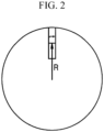
- FIG. 2 is a view for explaining the definition of a radial arrangement in a secondary particle according to an embodiment.
- the radially arranged structure means that, as shown in FIG. 2 , the thickness (t) direction of the primary particles is perpendicular to or within an angle of about ⁇ 5 ° of perpendicular to the direction (R) from the secondary particle from the center of the secondary particle to the surface.
- the secondary particles have lots of crystal planes, which transmit lithium to the outside, exposed to the surface and pores, which serve as a lithium diffusion passage, also exposed onto the surface, lithium diffusion may be improved, securing high initial efficiency and high capacity.
- the pores exposed to the surface of the secondary particles are directed toward a center of the secondary particles, which further promotes the lithium diffusion.
- the primary particles are radially arranged, and simultaneously, in the cross-section of the secondary particles, the number of the primary particles having a cross-sectional area of less than about 0.1 ⁇ m 2 satisfies a ratio of about 65% or more.
- the lithium diffusion is much slower from the surface of the primary particles to the inner portion than along the boundaries between the primary particles on the surface of the secondary particles. Accordingly, in an embodiment, by reducing a size of the primary particles, slow diffusion within the primary particles is reduced, and fast diffusion at boundaries between the primary particles is increased.
- This positive electrode active material is advantageous in rate characteristics due to the easy lithium diffusion, and a rechargeable lithium battery manufactured by applying the same exhibits improved initial charge and discharge capacity and efficiency, obtaining an effect of securing high-rate charging capacity and shortening high-speed charging time.
- a number ratio of the primary particles having a cross-sectional area of less than about 0.1 ⁇ m 2 may be, for example, about 65% to about 90%, for example, about 70% to about 85%.
- a number ratio of the primary particles having a cross-sectional area of greater than about 0.3 ⁇ m 2 may be less than or equal to about 5%, for example, about 0.1% to about 5%, or about 0.1% to about 4%.
- a number ratio of the primary particles having a cross-sectional area of about 0.1 ⁇ m 2 to about 0.3 ⁇ m 2 may be about 5% to about 30%, for example, about 11% to about 29.9%, or about 15% to about 29%.
- the positive electrode active material When the primary particles constituting the secondary particles of the positive electrode active material exhibit such a cross-sectional area distribution, the positive electrode active material has a reduced lithium ion diffusion distance, improving high-rate charge/discharge capacity, initial charge/discharge efficiency, and the like.
- the positive electrode active material satisfies the cross-sectional area distribution of the primary particles and simultaneously, a full width at half maximum of the peak corresponding to the (003) plane (FWHM 003 ) of less than or equal to about 0.125 in the X-ray diffraction analysis.
- FWHM 003 may be, for example, about 0.100 to about 0.125, about 0.110 to about 0.125, or about 0.100 to about 0.124.
- the secondary particles of the positive electrode active material may be described as a structure in which the (003) planes of the primary particles are oriented perpendicular to the surface of the secondary particles, wherein the primary particles satisfy the aforementioned area distribution and also, a peak full width at half maximum (FWHM) of the (003) plane of less than or equal to about 0.125, the (003) planes are sufficiently aligned to maximize capacity, and simultaneously, easily move lithium ions, increasing initial charge/discharge efficiency and high-rate charge/discharge capacity, and in addition, cycle-life characteristics may be improved by minimizing a stress according to contraction and expansion of the positive electrode active material.
- FWHM peak full width at half maximum
- the secondary particles of the positive electrode active material may include, for example, an inner portion having an irregular porous structure and an outer portion having a structure that has a least a portion of the primary particles radially arranged, that is, a radially arranged structure.
- the irregular porous structure is a structure having the primary particles and pores wherein a size, a shape, a position, and the like of the primary particles are irregular.
- the primary particles may be arranged without regularity unlike the outer portion.
- FIG. 3 is a schematic view showing a cross-sectional structure of the secondary particle of the positive electrode active material.
- the secondary particles 11 of the positive electrode active material have an outer portion 14 having a structure in which the plate-shaped primary particles 13 are arranged in a radial direction, and an inner portion 12 in which the primary particles 13 are irregularly arranged.
- the inner portion 12 there may be more empty spaces between the primary particles than the outer portion.
- a pore size and porosity of the inner portion may be large and irregular compared with those of the outer portion.
- an arrow indicates a movement direction of lithium ions.
- the positive electrode active material with this structure has a porous structure in the inner portion, so that a diffusion distance of lithium ions to the inner portion is reduced, and the pores may have an effect of alleviating volume changes between the primary particles occurring during the charge and discharge.
- the primary particles in the outer portion are radially arranged, so lithium ions may be easily intercalated into the surface, and a stress according to the volume changes may be minimized during the charge and discharge.
- This positive electrode active material may reduce resistance of a rechargeable lithium battery and improve charge and discharge efficiency and cycle-life characteristics thereof.
- the inner portion may include pores with a larger size than those of the outer portion.
- the pores in the inner portion may have a size of about 150 nm to about 1 ⁇ m, and the pores in the outer portion may have a size of less than about 150 nm.
- the pores in the outer portion lithium ions may be easily intercalated, while in the inner portion, a lithium diffusion distance may be short, and there is an effect of alleviating the volume changes of the positive electrode active material during the charge and discharge.
- the pores may have a size which is a diameter, when spherical or circular, and a length of a long axis when oval and the like, wherein the size is measured with a microscope such as SEM and the like.
- the secondary particles of the positive electrode active material may have open pores on the surface.
- the open pores may be pores of which a portion of walls are not closed, and the open pores on the surface may be connected to the outside and work as a passage through which a material comes in and out.
- These open pores may have a size of less than about 150 nm, for example, about 10 nm to about 148 nm. Since the primary particles in the outer portion of the secondary particles are radially arranged, the open pores on the surface may be in the form of facing a center from the surface of the secondary particles.
- the open pores may be formed to a depth of less than or equal to about 150 nm, for example, about 0.1 nm to about 100 nm, for example, about 1 nm to about 50 nm from the surface of the secondary particle.
- the size and depth of the open pores may be measured by the BJH (Barrett, Joyner and Halenda) method, which is a method derived through the adsorption or desorption content of nitrogen.
- the closed pores may exist in the inner portion of the secondary particle, and closed pores and/or open pores may exist in the outer portion.
- the closed pores may exclude or mostly exclude an electrolyte, while the open pores may include an electrolyte therein.
- the closed pores may be referred to as independent pores that are not connected to other pores since all of the walls of the pores are formed in a closed structure.
- the inner portion to a total of the secondary particles may have a radius ratio of about 45% to about 65%, for example, about 45% to about 60%, about 50% to about 60%, or about 50% to about 55%.
- initial charge/discharge efficiency and high temperature cycle-life characteristics may be improved.
- the outer portion to the total of the secondary particles may have a volume ratio of less than or equal to about 87%, for example, less than or equal to about 85%, about 80% to about 87%, or about 80% to about 85%.
- volume ratio of the outer portion of the secondary particles satisfies the ranges, initial charge/discharge efficiency and high temperature cycle-life characteristics may be further improved.
- the average particle diameter (D50) of the secondary particle of the positive electrode active material may be about 5 ⁇ m to about 20 ⁇ m, for example, about 8 ⁇ m to about 18 ⁇ m, or about 10 ⁇ m to about 15 ⁇ m.
- the positive electrode active material may realize high capacity and exhibit high initial charge/discharge efficiency and cycle-life characteristics.
- the average particle diameter (D50) of the secondary particles may be measured in a laser diffraction method by dispersing the positive electrode active material with a dispersing agent in distilled water. Or, a scanning electron microscope and the like is used to take an electron microscope image of the surface or the cross-section of the secondary particles. Here, the electron microscope is used to measure about 30 particle diameters and thus obtain a particle distribution, wherein a particle diameter D50 at a cumulative volume of 50 volume% is obtained as the average particle diameter.
- the lithium nickel-based composite oxide may be represented by Chemical Formula 1.
- Chemical Formula 1 Li a1 Ni x1 M 1 y1 M 2 1-x1- y 1 O 2-z X z
- M 1 and M 2 are each independently at least one element selected from Al, B, Ba, Ca, Ce, Co, Cr, Fe, Mg, Mn, Mo, Nb, Si, Sr, Ti, V, W, and Zr, and X is at least one element selected from F, P, and S.
- Chemical Formula 1 for example, 0.4 ⁇ x1 ⁇ 1 and 0 ⁇ y1 ⁇ 0.6, 0.5 ⁇ x1 ⁇ 1 and 0 ⁇ y1 ⁇ 0.5, 0.6 ⁇ x1 ⁇ 1 and 0 ⁇ y1 ⁇ 0.4, or 0.7 ⁇ x1 ⁇ 1 and 0 ⁇ y1 ⁇ 0.3, 0.8 ⁇ x1 ⁇ 1 and 0 ⁇ y1 ⁇ 0.2, or 0.9 ⁇ x1 ⁇ 1 and 0 ⁇ y1 ⁇ 0.1.
- the lithium nickel-based composite oxide may be, for example, represented by Chemical Formula 2.
- Chemical Formula 2 Li a2 Ni x2 Co y2 M 3 1-x2-y2 O 2-z X z
- M 3 is at least one element selected from Al, B, Ba, Ca, Ce, Cr, Fe, Mg, Mn, Mo, Nb, Si, Sr, Ti, V, W, and Zr
- X is at least one element selected from F, P, and S.
- Chemical Formula 2 for example, 0.3 ⁇ x2 ⁇ 0.99 and 0.01 ⁇ y2 ⁇ 0.7, 0.4 ⁇ x2 ⁇ 0.99 and 0.01 ⁇ y2 ⁇ 0.6, 0.5 ⁇ x2 ⁇ 0.99 and 0.01 ⁇ y2 ⁇ 0.5, or 0.6 ⁇ x2 ⁇ 0.99 and 0.01 ⁇ y2 ⁇ 0.4, 0.7 ⁇ x2 ⁇ 0.99 and 0.01 ⁇ y2 ⁇ 0.3, 0.8 ⁇ x2 ⁇ 0.99 and 0.01 ⁇ y2 ⁇ 0.2, or 0.9 ⁇ x2 ⁇ 0.99 and 0.01 ⁇ y2 ⁇ 0.1.
- the lithium nickel-based composite oxide may be, for example, represented by Chemical Formula 3.
- Chemical Formula 3 Li a3 Ni x3 Co y3 M 4 z3 M 5 1-x3-y3-z3 O 2-z X z
- M 4 is at least one element selected from Al
- Mn is at least one element selected from B, Ba, Ca, Ce, Cr, Fe, Mg, Mo, Nb, Si, Sr, Ti, V, W, and Zr
- X is at least one element selected from F, P, and S.
- 0.4 ⁇ x3 ⁇ 0.98, 0.01 ⁇ y3 ⁇ 0.59, and 0.01 ⁇ z3 ⁇ 0.59 may be 0.5 ⁇ x3 ⁇ 0.98, 0.01 ⁇ y3 ⁇ 0.49, and 0.01 ⁇ z3 ⁇ 0.49, or 0.6 ⁇ x3 ⁇ 0.98, 0.01 ⁇ y3 ⁇ 0.39, and 0.01 ⁇ z3 ⁇ 0.39, or 0.7 ⁇ x3 ⁇ 0.98, 0.01 ⁇ y3 ⁇ 0.29, and 0.01 ⁇ z3 ⁇ 0.29, or 0.8 ⁇ x3 ⁇ 0.98, 0.01 ⁇ y3 ⁇ 0.19, and 0.01 ⁇ z3 ⁇ 0.19, or 0.9 ⁇ x3 ⁇ 0.98, 0.01 ⁇ y3 ⁇ 0.09, and 0.01 ⁇ z3 ⁇ 0.09.
- a method of preparing a positive electrode active material for a rechargeable lithium battery includes mixing a positive electrode active material precursor including a nickel-based composite hydroxide and a lithium raw material, and heat-treating the resultant.
- the positive electrode active material precursor may be prepared by a co-precipitation method.
- a nickel raw material and optionally, a metal raw material other than the nickel are mixed to prepare a composite metal raw material, and then, a complexing agent and a pH controlling agent are added thereto to control pH of the mixture and perform a co-precipitation reaction, preparing a nickel-based composite hydroxide having a desired composition.
- the complexing agent serves to control a reaction rate of the formation of a precipitate in the co-precipitation reaction, and may be, for example, ammonium hydroxide (NHOH), ammonium sulfate, or citric acid.
- NHOH ammonium hydroxide
- ammonium sulfate ammonium sulfate
- citric acid citric acid
- the pH controlling agent may be, for example, sodium hydroxide (NaOH), sodium carbonate (Na 2 CO 3 ), sodium oxalate (Na 2 C 2 O 4 ), or the like.
- the pH of the mixture may be adjusted, for example, in the range of about 10 to about 13.
- the co-precipitation reaction may proceed in several steps, for example, 2 steps, 3 steps, or 4 steps.
- a concentration of the complexing agent, an input rate of the composite metal raw material, the pH range, a reaction temperature, reaction time, stirring power, and the like may be differently adjusted.
- a secondary particle-type positive electrode active material precursor in which at least a portion of the primary particles are radially arranged, is prepared, and in addition, secondary particles having different internal and external shapes are prepared.
- the positive electrode active material precursor including a nickel-based composite hydroxide is prepared through each first, second, and third step process of forming a core, an intermediate layer, and a shell.
- the complex agent may have a concentration of 0.1 M to 0.7 M, the input amount of the complex agent may be in a range of 6 mL/min to 12 mL/min, the metal raw materials may have concentrations of 0.1 M to 3.5 M, the input amounts of the metal raw materials may be in a range of 50 ml/min to 100 ml/min.
- the metal raw materials and the complex agent are added to a resulting material of the first step reaction to control pH of the reaction mixture, and then, a reaction of the second step is performed, a concentration of the complex agent may be 0.3 M to 1.0 M, the input amount of the complex agent may be in a range of 8 ml/min to 15 ml/min, the metal raw materials may have concentrations of 0.1 M to 3.5 M, the input amounts of the metal raw materials may be in a range of 90 ml/min to 120 ml/min.
- the input amounts and the concentrations of the metal raw materials and the complex agent may be increased in order to prevent a growth rate decrease of particles after reacting a reaction product from the second step for a predetermined time
- the concentration of the complex agent may be in a range of 0.35 M to 1.0 M
- the input amount of the complex agent may be in a range of 12 ml/min to 20 ml/min
- the metal raw materials may have concentrations of 0.1 M to 3.5 M
- the input amounts of the metal raw materials may be in a range of 120 ml/min to 150 ml/min.
- the pH of the reaction mixture may be adjusted in a range of 10 to 12.
- the nickel-based composite hydroxide may be, for example, represented by Chemical Formula 11. [Chemical Formula 11] Ni x11 M 11 y11 M 12 1-x11-y11 (OH) 2
- M 11 and M 12 are each independently selected from Al, B, Ba, Ca, Ce, Co, Cr, F, Fe, Mg, Mn, Mo, Nb, P, S, Si, Sr, Ti, V, W, Zr, and a combination thereof.
- the nickel-based composite hydroxide may be represented by Chemical Formula 12 or Chemical Formula 13.
- Chemical Formula 12 Ni x12 CO y12 M 13 1-x12-y12 (OH) 2
- M 13 is selected from Al, B, Ba, Ca, Ce, Cr, F, Fe, Mg, Mn, Mo, Nb, P, S, Si, Sr, Ti, V, W, Zr, and a combination thereof.
- M 14 is selected from Al, Mn, and a combination thereof
- M 15 is selected from B, Ba, Ca, Ce, Cr, F, Fe, Mg, Mo, Nb, P, S, Si, Sr, Ti, V, W, Zr, and a combination thereof.
- the average particle diameter (D50) of the positive electrode active material precursor may be, for example, about 5 ⁇ m to about 20 ⁇ m, or about 8 ⁇ m to about 18 ⁇ m.
- the particle diameter of the secondary particle may be measured by an optical microscopic image such as a scanning electron microscope on the surface or cross-section of the secondary particle. A particle size distribution is obtained by measuring about 30 particle diameters through an optical microscope, and the D50 value, which is the particle diameter at a point where the cumulative volume is about 50 volume%, may be taken as the average particle diameter.
- the aforementioned positive electrode active material may be obtained by mixing the lithium raw material with the prepared positive electrode active material precursor and then performing heat-treatment.
- the lithium raw material may be, for example, Li 2 CO 3 , LiOH, a hydrate thereof, or a combination thereof, and may be mixed in a ratio of about 0.8 mole to about 1.8 mole, or about 0.9 mole to about 1.2 mole with respect to 1 mole of the nickel-based composite hydroxide.
- the heat-treatment may be performed, for example, at about 600 °C to about 900 °C or about 600 °C to about 800 °C.
- the heat-treatment may include a temperature-raising step and a temperature-maintaining step, wherein the temperature-raising time may be longer than the temperature-maintaining time.
- the temperature-raising time may be about 6 hours to about 16 hours, and the temperature-maintaining time may be about 1 hour to about 9 hours, wherein the temperature-raising time may be longer than the temperature-maintaining time.
- the temperature-raising time may be, for example, about 6 hours to about 15 hours, about 6 hours to about 14 hours, about 6 hours to about 13 hours, or about 7 hours to about 12 hours, and the temperature-maintaining time may be about 2 hours to about 9 hours or about 3 hours to about 8 hours.
- a ratio of (temperature-raising time):(temperature-maintaining time) may be about 1.1:1 to about 10:1, for example, about 1.1:1 to about 8:1, about 1.1:1 to about 6:1, about 1.1:1 to about 5:1, or about 1.1:1 to about 4:1.
- the heat-treatment profile is adjusted to effectively control the primary particle cross-sectional area distribution and the peak full width at half maximum (FWHM) range of the (003) plane.
- the positive electrode for a rechargeable lithium battery may include a current collector and a positive electrode active material layer on the current collector.
- the positive electrode active material layer may include a positive electrode active material, and may further include a binder and/or a conductive material.
- the binder improves binding properties of positive electrode active material particles with one another and with a current collector.
- examples thereof may be polyvinyl alcohol, carboxylmethyl cellulose, hydroxypropyl cellulose, diacetyl cellulose, polyvinylchloride, carboxylated polyvinylchloride, polyvinylfluoride, an ethylene oxide-containing polymer, polyvinylpyrrolidone, polyurethane, polytetrafluoroethylene, polyvinylidene fluoride, polyethylene, polypropylene, a styrene-butadiene rubber, an acrylated styrene-butadiene rubber, an epoxy resin, nylon, and the like, but are not limited thereto.
- the content of the binder in the positive electrode active material layer may be about 1 wt% to about 5 wt% based on the total weight of the positive electrode active material layer.
- the conductive material is included to provide electrode conductivity. Any electrically conductive material may be used as a conductive material unless it causes a chemical change.
- the conductive material may include a carbon-based material such as natural graphite, artificial graphite, carbon black, acetylene black, ketjen black, a carbon fiber, carbon nanotube, and the like; a metal-based material of a metal powder or a metal fiber including copper, nickel, aluminium, silver, and the like; a conductive polymer such as a polyphenylene derivative; or a mixture thereof.
- the content of the conductive material in the positive electrode active material layer may be about 1 wt% to about 5 wt% based on the total weight of the positive electrode active material layer.
- An aluminium foil may be used as the positive electrode current collector, but the present disclosure is not limited thereto.
- the negative electrode for a rechargeable lithium battery includes a current collector and a negative electrode active material layer on the current collector.
- the negative electrode active material layer includes a negative electrode active material and may further include a binder and/or a conductive material.
- the negative electrode active material may include a material that reversibly intercalates/deintercalates lithium ions, a lithium metal, a lithium metal alloy, a material capable of doping/dedoping lithium, or transition metal oxide.
- the material that reversibly intercalates/deintercalates lithium ions may include, for example crystalline carbon, amorphous carbon, or a combination thereof as a carbon-based negative electrode active material.
- the crystalline carbon may be non-shaped, or sheet, flake, spherical, or fiber shaped natural graphite or artificial graphite.
- the amorphous carbon may be a soft carbon, a hard carbon, a mesophase pitch carbonization product, calcined coke, and the like.
- the lithium metal alloy includes an alloy of lithium and a metal selected from Na, K, Rb, Cs, Fr, Be, Mg, Ca, Sr, Si, Sb, Pb, In, Zn, Ba, Ra, Ge, Al, and Sn.
- the material capable of doping/dedoping lithium may be a Si-based negative electrode active material or a Sn-based negative electrode active material.
- the Si-based negative electrode active material may include silicon, a silicon-carbon composite, SiO x (0 ⁇ x ⁇ 2), a Si-Q alloy (wherein Q is an alkali metal, an alkaline-earth metal, a Group 13 element, a Group 14 element, a Group 15 element, a Group 16 element, a transition metal, a rare earth element, and a combination thereof, but not Si) and the Sn-based negative electrode active material may include Sn, SnO 2 , a Sn-R alloy (wherein R is an alkali metal, an alkaline-earth metal, a Group 13 element, a Group 14 element, a Group 15 element, a Group 16 element, a transition metal, a rare earth element, and a combination thereof, but not Sn).
- the elements Q and R may be selected from Mg, Ca, Sr, Ba, Ra, Sc, Y, Ti, Zr, Hf, Rf, V, Nb, Ta, Db, Cr, Mo, W, Sg, Tc, Re, Bh, Fe, Pb, Ru, Os, Hs, Rh, Ir, Pd, Pt, Cu, Ag, Au, Zn, Cd, B, Al, Ga, Sn, In, TI, Ge, P, As, Sb, Bi, S, Se, Te, Po, and a combination thereof.
- the silicon-carbon composite may be, for example, a silicon-carbon composite including a core including crystalline carbon and silicon particles and an amorphous carbon coating layer disposed on the surface of the core.
- the crystalline carbon may be artificial graphite, natural graphite, or a combination thereof.
- the amorphous carbon precursor may be a coal-based pitch, mesophase pitch, petroleum-based pitch, coal-based oil, petroleum-based heavy oil, or a polymer resin such as a phenol resin, a furan resin, or a polyimide resin.
- the content of silicon may be about 10 wt% to about 50 wt% based on the total weight of the silicon-carbon composite.
- the content of the crystalline carbon may be about 10 wt% to about 70 wt% based on the total weight of the silicon-carbon composite, and the content of the amorphous carbon may be about 20 wt% to about 40 wt% based on the total weight of the silicon-carbon composite.
- a thickness of the amorphous carbon coating layer may be about 5 nm to about 100 nm.
- An average particle diameter (D50) of the silicon particles may be about 10 nm to about 20 ⁇ m.
- the average particle diameter (D50) of the silicon particles may be preferably about 10 nm to about 200 nm.
- the silicon particles may exist in an oxidized form, and in this case, an atomic content ratio of Si:O in the silicon particles indicating a degree of oxidation may be a weight ratio of about 99:1 to about 33:67.
- the silicon particles may be SiO x particles, and in this case, the range of x in SiO x may be greater than about 0 and less than about 2.
- the average particle diameter (D50) is measured by a particle size analyzer and refers to a diameter of particles having a cumulative volume of 50 volume% in the particle size distribution.
- the Si-based negative electrode active material or Sn-based negative electrode active material may be mixed with the carbon-based negative electrode active material.
- the mixing ratio may be a weight ratio of about 1:99 to about 90:10.
- the negative electrode active material may be included in an amount of about 95 wt% to about 99 wt% based on the total weight of the negative electrode active material layer.
- the negative electrode active material layer further includes a binder, and may optionally further include a conductive material.
- the content of the binder in the negative electrode active material layer may be about 1 wt% to about 5 wt% based on the total weight of the negative electrode active material layer.
- the negative electrode active material layer may include about 90 wt% to about 98 wt% of the negative electrode active material, about 1 wt% to about 5 wt% of the binder, and about 1 wt% to about 5 wt% of the conductive material.
- the binder serves to well adhere the negative electrode active material particles to each other and also to adhere the negative electrode active material to the current collector.
- the binder may be a water-insoluble binder, a water-soluble binder, or a combination thereof.
- water-insoluble binder examples include polyvinyl chloride, carboxylated polyvinyl chloride, polyvinyl fluoride, an ethylene oxide-containing polymer, an ethylene propylene copolymer, polystyrene, polyvinylpyrrolidone, polyurethane, polytetrafluoroethylene, polyvinylidene fluoride, polyethylene, polypropylene, polyamideimide, polyimide, or a combination thereof.
- the water-soluble binder may include a rubber binder or a polymer resin binder.
- the rubber binder may be selected from a styrene-butadiene rubber, an acrylated styrene-butadiene rubber, an acrylonitrile-butadiene rubber, an acrylic rubber, a butyl rubber, a fluororubber, and a combination thereof.
- the polymer resin binder may be selected from polyethylene oxide, polyvinylpyrrolidone, polyepichlorohydrin, polyphosphazene, polyacrylonitrile, an ethylene propylene diene copolymer, polyvinylpyridine, chlorosulfonated polyethylene, latex, a polyester resin, an acrylic resin, a phenol resin, an epoxy resin, polyvinyl alcohol, and a combination thereof.
- a cellulose-based compound capable of imparting viscosity may be further included.
- the cellulose-based compound one or more of carboxymethyl cellulose, hydroxypropylmethyl cellulose, methyl cellulose, or alkali metal salts thereof may be mixed and used.
- the alkali metal Na, K or Li may be used.
- the amount of the thickener used may be about 0.1 parts by weight to about 3 parts by weight based on 100 parts by weight of the negative electrode active material.
- the conductive material is included to provide electrode conductivity. Any electrically conductive material may be used as a conductive material unless it causes a chemical change.
- the conductive material include a carbon-based material such as natural graphite, artificial graphite, carbon black, acetylene black, ketjen black, a carbon fiber, carbon nanotube, and the like; a metal-based material of a metal powder or a metal fiber including copper, nickel, aluminium, silver, and the like; a conductive polymer such as a polyphenylene derivative; or a mixture thereof.
- the negative electrode current collector may include one selected from a copper foil, a nickel foil, a stainless steel foil, a titanium foil, a nickel foam, a copper foam, a polymer substrate coated with a conductive metal, and a combination thereof.
- Another embodiment provides a rechargeable lithium battery including a positive electrode, a negative electrode, and an electrolyte.
- the rechargeable lithium battery may include, for example, a positive electrode, a negative electrode, a separator between the positive electrode and the negative electrode, and an electrolyte, wherein the electrolyte may be in the form of a liquid or a gel polymer.
- the rechargeable lithium battery may be an all-solid-state battery including a positive electrode, a negative electrode, and a solid electrolyte, or a semi-solid battery including a positive electrode, a negative electrode, and a semi-solid electrolyte.
- the semi-solid may mean a state including both a solid component and a liquid component, or a state in which most of the solid component is included but a portion of the liquid component is included.
- the all-solid-state battery and the semi-solid battery may not include a separator.
- the positive electrode active material according to an embodiment can realize very high charge/discharge efficiency and high temperature cycle-life while realizing a high capacity due to its shape, so it is suitable for application to the aforementioned types of batteries and exhibits excellent performance in each battery.
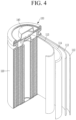
- FIG. 4 is a schematic view illustrating a rechargeable lithium battery according to an embodiment.
- the rechargeable lithium battery 100 includes a battery cell including a positive electrode 114, a negative electrode 112 facing the positive electrode 114, a separator 113 between the positive electrode 114 and the negative electrode 112, an electrolyte for a rechargeable lithium battery impregnating the positive electrode 114, negative electrode 112, and separator 113, a battery case 120 containing the battery cell, and a sealing member 140 sealing the battery case 120.
- the electrolyte includes a non-aqueous organic solvent and a lithium salt.
- the non-aqueous organic solvent serves as a medium for transmitting ions taking part in the electrochemical reaction of a battery.
- the non-aqueous organic solvent may include a carbonate-based, ester-based, ether-based, ketone-based, alcohol-based, or aprotic solvent.
- the carbonate-based solvent may include dimethyl carbonate (DMC), diethyl carbonate (DEC), dipropyl carbonate (DPC), methylpropyl carbonate (MPC), ethylpropyl carbonate (EPC), methylethyl carbonate (MEC), ethylene carbonate (EC), propylene carbonate (PC), butylene carbonate (BC), and the like.
- the ester-based solvent may include methyl acetate, ethyl acetate, n-propyl acetate, dimethylacetate, methylpropionate, ethylpropionate, ⁇ -butyrolactone, decanolide, valerolactone, mevalonolactone, caprolactone, and the like.
- the ether-based solvent may include dibutyl ether, tetraglyme, diglyme, dimethoxyethane, 2-methyltetrahydrofuran, tetrahydrofuran, and the like and the ketone-based solvent may include cyclohexanone, and the like.
- the alcohol-based solvent may include ethanol, isopropyl alcohol, and the like and the aprotic solvent may include nitriles such as R-CN (wherein, R is a C2 to C20 linear, branched, or cyclic hydrocarbon group, and may include a double bond, an aromatic ring, or an ether bond), and the like, amides such as dimethyl formamide, and the like, dioxolanes such as 1,3-dioxolane, sulfolanes, and the like.
- R-CN wherein, R is a C2 to C20 linear, branched, or cyclic hydrocarbon group, and may include a double bond, an aromatic ring, or an ether bond
- amides such as dimethyl formamide, and the like
- dioxolanes such as 1,3-dioxolane, sulfolanes, and the like.
- the non-aqueous organic solvent may be used alone or in a mixture.
- the mixture ratio may be controlled in accordance with a desirable battery performance.
- the carbonate-based solvent may include a mixture with a cyclic carbonate and a chain carbonate.
- the electrolyte may exhibit excellent performance.
- the non-aqueous organic solvent may further include an aromatic hydrocarbon-based organic solvent in the carbonate-based solvent.
- the carbonate-based solvent and the aromatic hydrocarbon-based organic solvent may be mixed in a volume ratio of about 1:1 to about 30:1.
- aromatic hydrocarbon-based solvent an aromatic hydrocarbon-based compound represented by Chemical Formula I may be used.
- R 4 to R 9 are the same or different and are selected from hydrogen, a halogen, a C1 to C10 alkyl group, a C1 to C10 haloalkyl group, and a combination thereof.
- aromatic hydrocarbon-based solvent may be selected from benzene, fluorobenzene, 1,2-difluorobenzene, 1,3-difluorobenzene, 1,4-difluorobenzene, 1,2,3-trifluorobenzene, 1,2,4-trifluorobenzene, chlorobenzene, 1,2-dichlorobenzene, 1,3-dichlorobenzene, 1,4-dichlorobenzene, 1,2,3-trichlorobenzene, 1,2,4-trichlorobenzene, iodobenzene, 1,2-diiodobenzene, 1,3-diiodobenzene, 1,4-diiodobenzene, 1,2,3-triiodobenzene, 1,2,4-triiodobenzene, toluene, fluorotoluene, 2,3-difluorotoluene, 2,4-difluorobenz
- the electrolyte may further include vinylene carbonate or an ethylene carbonate-based compound of Chemical Formula II in order to improve cycle-life of a battery.
- R 10 and R 11 are the same or different, and are selected from hydrogen, a halogen, a cyano group, a nitro group, and fluorinated C1 to C5 alkyl group, provided that at least one of R 10 and R 11 is selected from a halogen, a cyano group, a nitro group, and fluorinated C1 to C5 alkyl group, but both of R 10 and R 11 are not hydrogen.
- Examples of the ethylene carbonate-based compound may be difluoroethylene carbonate, chloroethylene carbonate, dichloroethylene carbonate, bromoethylene carbonate, dibromoethylene carbonate, nitroethylene carbonate, cyanoethylene carbonate, or fluoroethylene carbonate.
- the amount of the additive for improving cycle-life may be used within an appropriate range.
- the lithium salt dissolved in the non-aqueous organic solvent supplies lithium ions in a battery, enables a basic operation of a rechargeable lithium battery, and improves transportation of the lithium ions between positive and negative electrodes.
- lithium salt examples include at least one supporting salt selected from LiPF 6 , LiBF 4 , LiSbF 6 , LiAsF 6 , LiN(SO 2 C 2 F 5 ) 2 , Li(CF 3 SO 2 ) 2 N, LiN(SO 3 C 2 F 5 ) 2 , Li(FSO 2 ) 2 N (lithium bis(fluorosulfonyl)imide: LiFSI), LiC 4 F 9 SO 3 , LiClO 4 , LiAlO 2 , LiAlCl 4 , LiPO 2 F 2 , LiN(C x F 2x+1 SO 2 )(C y F 2y+1 SO 2 ) (wherein x and y are natural numbers, for example, an integer ranging from 1 to 20), lithium difluoro(bisoxalato) phosphate, LiCI, Lil, LiB(C 2 O 4 ) 2 (lithium bis(oxalato) borate, LiBOB), and lithium difluoro(oxal)
- the lithium salt may be used in a concentration ranging from about 0.1 M to about 2.0 M.
- an electrolyte may have excellent performance and lithium ion mobility due to optimal electrolyte conductivity and viscosity.
- the separator 113 separates a positive electrode 114 and a negative electrode 112 and provides a transporting passage for lithium ions and may be any generally-used separator in a lithium ion battery. In other words, it may have low resistance to ion transport and excellent impregnation for an electrolyte.
- the separator 113 may include glass fiber, polyester, polyethylene, polypropylene, polytetrafluoroethylene, or a combination thereof, and may be in the form of a non-woven fabric or a woven fabric.
- a polyolefin-based polymer separator such as polyethylene and polypropylene may be mainly used.
- a coated separator including a ceramic component or a polymer material may be used.
- it may have a mono-layered or multilayered structure.
- Rechargeable lithium batteries may be classified as lithium ion batteries, lithium ion polymer batteries, and lithium polymer batteries according to the presence of a separator and the kind of electrolyte used therein.
- the rechargeable lithium batteries may have a variety of shapes and sizes, and include cylindrical, prismatic, coin, or pouch-type batteries, and may be thin film batteries or may be rather bulky in size. Structures and manufacturing methods for lithium ion batteries pertaining to this disclosure are well known in the art.
- the rechargeable lithium battery according to an embodiment may be used in an electric vehicle (EV), a hybrid electric vehicle such as a plug-in hybrid electric vehicle (PHEV), and portable electronic device because it implements a high capacity and has excellent storage stability, cycle-life characteristics, and high rate characteristics at high temperatures.
- EV electric vehicle
- PHEV plug-in hybrid electric vehicle
- portable electronic device because it implements a high capacity and has excellent storage stability, cycle-life characteristics, and high rate characteristics at high temperatures.
- nickel sulfate, cobalt sulfate, and aluminium nitrate were used as metal raw materials.
- ammonia water having a concentration of 0.40 M was put in a reactor. While metal raw materials and a complexing agent (NH 4 OH) were added thereto respectively at 85 ml/min and 10 ml/min at 50 °C under a stirring power of 2.5 kW/m 3 , a reaction was started.
- metal raw materials and a complexing agent NH 4 OH
- the reaction was performed for 6 hours. As a result of the reaction, it was confirmed that the average sizes of the obtained core particles were in the range of about 6.5 ⁇ m to 7.5 ⁇ m, and the second step was performed as follows.
- the metal raw materials and the complexing agent were added thereto respectively at 107 ml/min and 15 ml/min, while the reaction temperature was maintained at 50 °C, so that a concentration of the complexing agent was adjusted to be 0.45 M. While adding NaOH thereto in order to maintain pH, the reaction was performed for 18 hours. At this time, the stirring power was lowered to 2.0 kW/m 3 , which was lower than the first step, and the reaction proceeded. By performing this reaction, it was confirmed that the average sizes of the product particles containing the core and the intermediate layer were 11.5 ⁇ m to 12 ⁇ m, and the third step was performed as follows.
- the metal raw material and the complexing agent were added at the rates of 142 ml/min and 19 ml/min, respectively, so that the concentration of the complexing agent was maintained the same as in the second step.
- the reaction was performed for 10 hours. At this time, the stirring power was lowered to 1.0 kW/m 3 , which was lower than in the second step, and the reaction proceeded.
- nickel-based hydroxide Ni 0.945 Co 0.04 Al 0.015 (OH) 2
- OH positive electrode active material precursor
- the final positive electrode active material prepared in Example was in a form of a secondary particle including an inner portion having an irregular porous structure and an outer portion having a radially arranged structure, and the peak full width at half maximum (FWHM) of the (003) plane in X-ray diffraction analysis was 0.1208.
- 96 wt% of the obtained positive electrode active material, 2 wt% of polyvinylidene fluoride, 2 wt% of carbon nanotube, and N-methylpyrrolidone as a solvent were mixed in a mixer to prepare slurry for a positive electrode active material layer.
- the slurry was coated on an aluminium foil into an electrode plate and then, dried at 135 °C for at least 3 hours, roll-pressed, and vacuum-dried, manufacturing a positive electrode.
- the positive electrode and a lithium metal counter electrode were used to manufacture a coin half-cell. Between the positive electrode and the lithium metal counter electrode, a separator formed of a porous polyethylene film (thickness: about 16 ⁇ m) was interposed, and an electrolyte solution was injected thereinto.
- the electrolyte solution was prepared by mixing ethylene carbonate (EC) and ethylmethyl carbonate (EMC) in a volume ratio of 3:5 and dissolving 1.1 M LiPF 6 in the mixed solvent.
- Nickel sulfate, cobalt sulfate, and aluminium nitrate were dissolved in distilled water at a mole ratio of 94.5:4:1.5 to prepare a metal raw material mixed solution.
- a dilute ammonia water (NH 4 OH) solution and sodium hydroxide (NaOH) as a precipitant were prepared to form a complex compound.
- the metal raw material mixed solution was continuously added, and sodium hydroxide was added to maintain the pH inside the reactor.
- the reaction proceeded slowly for about 80 hours, and when the reaction was stabilized, the product that overflowed was collected and the drying process proceeded.
- Ni 0.945 Co 0.04 Al 0.015 (OH) 2 nickel-based composite hydroxide in the form of a secondary particle in which primary particles were aggregated was prepared.
- the peak full width at half maximum (FWHM) of the (003) plane was confirmed to be 0.1292.
- the positive electrode active material of Comparative Example 1 had a radial structure and a peak full width at half maximum (FWHM) of the (003) plane exceeded 0.125. It was also the case that the ratio of large primary particles was large.
- nickel sulfate, cobalt sulfate, and aluminium nitrate were used as metal raw materials.
- ammonia water having a concentration of 0.35 M was put in a reactor. While metal raw materials and a complexing agent were added thereto respectively at 85 ml/min and 9 ml/min at 50 °C under a stirring power of 2.5 kW/m 3 , a reaction was started. While NaOH was added thereto to maintain pH, the reaction was performed for 6 hours. As a result of the reaction, it was confirmed that the average sizes of the obtained core particles were in the range of about 5.5 ⁇ m to 6.5 ⁇ m, and the second step was performed as follows.
- the metal raw materials and the complexing agent were added thereto respectively at 107 ml/min and 15 ml/min, while the reaction temperature was maintained at 50 °C, so that the complexing agent adjusted a concentration of 0.45 M. While adding NaOH thereto in order to maintain pH, the reaction was performed for 18 hours. At this time, the stirring power was lowered to 1.5 kW/m 3 , which was lower than the first step, and the reaction proceeded. By performing this reaction, it was confirmed that the average sizes of the product particles containing the core and the intermediate layer were 11.5 ⁇ m to 12 ⁇ m, and the third step was performed as follows.
- the metal raw material and the complexing agent were added at the rates of 142 ml/min and 19 ml/min, respectively, so that the concentration of the complexing agent was maintained the same as in the second step.
- the reaction was performed for 10 hours. At this time, the stirring power was lowered to 1.0 kW/m 3 , which was lower than in the second step, and the reaction proceeded.
- nickel-based hydroxide Ni 0.945 Co 0.04 Al 0.015 (OH) 2
- positive electrode active material precursor Ni 0.945 Co 0.04 Al 0.015 (OH) 2
- a positive electrode active material precursor, a positive electrode active material, a positive electrode, and a battery cell were prepared according to the same method as in Example, except that the nickel-based composite hydroxide and LiOH were mixed, then the temperature was raised to 700 °C for 5 hours, and heat-treatment is performed for 10 hours.
- the peak full width at half maximum (FWHM) of the (003) plane was confirmed to be 0.136.
- the positive electrode active material of Comparative Example 2 had a radial structure and a peak full width at half maximum (FWHM) of the (003) plane exceeded 0.125. It was also a case where a proportion of large primary particles was small.
- Nickel sulfate, cobalt sulfate, and aluminium nitrate were dissolved in distilled water at a mole ratio of 94.5:4:1.5 to prepare a metal raw material mixed solution.
- a dilute ammonia water (NH 4 OH) solution and sodium hydroxide (NaOH) as a precipitant were prepared to form a complex compound.
- the metal raw material mixed solution was continuously added, and sodium hydroxide was added to maintain the pH inside the reactor.
- the reaction proceeded slowly for about 80 hours, and when the reaction was stabilized, the product that overflowed was collected and the drying process proceeded.
- Ni 0.945 Co 0.04 Al 0.015 (OH) 2 nickel-based composite hydroxide in a form of a secondary particle in which primary particles were not radially arranged was prepared.
- the peak full width at half maximum (FWHM) of the (003) plane was confirmed to be 0.125. That is, the positive electrode active material of Comparative Example 3 had a peak full width at half maximum (FWHM) of 0.125 or less, but had a non-radial structure.
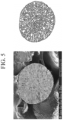
- FIG. 5 is a scanning electron microscope (SEM) image of a cross-section of the positive electrode active material according to Example which is cut with a focused ion beam (FIB) and an image obtained by inputting the image to a computer and contouring the primary particles with an Image J program.
- FIG. 6 is a cross-section SEM image of the positive electrode active material of Comparative Example 1 and an image obtained by contour-processing the primary particles
- FIG. 7 is a cross-section SEM image of the positive electrode active material of Comparative Example 2 and an image obtained by contour-processing the primary particle.
- the positive electrode active material of Example is secondary particles including an inner portion having an irregular porous structure and an outer portion having a radial structure; in the positive electrode active material of Comparative Example 1, a portion of the primary particles are radially arranged, but there are many large primary particles; and in the positive electrode active material of Comparative Example 2, a portion of the primary particles are radially arranged, but in the inner portion, a pore layer is not developed.
- the positive electrode active materials according to Example and Comparative Examples 1 and 2 were measured regarding a cross-sectional area distribution of primary particles by contour-processing the primary particle in the FIB cross-section SEM images, as shown in FIGS. 5 to 7 , and measuring cross-sectional areas of the primary particles with an Image J program.
- FIG. 5 A cross-sectional area distribution of primary particles by contour-processing the primary particle in the FIB cross-section SEM images, as shown in FIGS. 5 to 7 , and measuring cross-sectional areas of the primary particles with an Image J program.
- a black bar graph represents a ratio of the number of primary particles having a cross-sectional area of smaller than 0.1 ⁇ m 2
- a hatched bar graph represents a ratio of the number of primary particles having a cross-sectional area of 0.1 ⁇ m 2 to 0.3 ⁇ m 2
- a dotted line graph represents a ratio of the number of large primary particles having a cross-sectional area of larger than 0.3 ⁇ m 2 .
- the ratio of the number of primary particles having a cross-sectional area of less than 0.1 ⁇ m 2 is 37% in Comparative Example 1 and 60% in Comparative Example 2 but 77% in Example, which is much higher than the comparative examples and satisfies greater than or equal to 65%.
- the ratio of the number of primary particles having a cross-sectional area of greater than 0.3 ⁇ m 2 is about 33% in Comparative Example 1 and about 10% in Comparative Example 2 but about 2% in Example, which is much lower than the comparative examples.
- X-ray diffraction analysis was performed on the positive electrode active materials according to Example and Comparative Examples 1 to 3 to take a peak full width at half maximum (FWHM) of the (003) plane, and the results are shown in FIG. 9 .
- the bar graph shows a peak full width at half maximum (FWHM) of the (003) plane
- the dotted line graph shows initial charge/discharge efficiency described later.
- Comparative Examples 1 and 2 exhibit a peak full width at half maximum (FWHM) of greater than 0.125 of the (003) plane, but Comparative Example 3 and Example satisfy less than or equal to 0.125.
- FWHM full width at half maximum
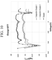
- a log graph of a lithium ion diffusion coefficient (D GITT ) according to a charging voltage was derived by using Galvanostatic Intermittent Titration Technique (GITT), and the results are shown in FIG. 10 .
- Example exhibits a higher lithium ion diffusion coefficient than Comparative Examples 1 and 2 and thus, is advantageous for kinetically high-rate charging.
- the battery cells according to Example and Comparative Examples 1 to 3 were charged to an upper limit voltage of 4.25 V at a constant current of 0.2 C at 25 °C and discharged to a discharge cut-off voltage of 3.0 V at a constant current of 0.2 C to perform initial charge and discharge.
- the bar graph exhibits initial charge capacity and initial discharge capacity
- the dotted line graph exhibits a ratio of the initial discharge capacity to the initial charge capacity, which is initial efficiency.
- the initial efficiency is additionally marked by a dotted line graph.
- Example exhibits high initial charge capacity and initial discharge capacity and much improved initial charge/discharge efficiency, compared with the comparative examples.
- the positive electrode active material of Example has many primary particles having a radially-arranged structure, a small cross-sectional area, for example, a cross-sectional area of less than 0.1 ⁇ m 2 and simultaneously, a very small peak full width at half maximum (FWHM) of less than or equal to 0.125 of the (003) plane and thus low diffusion resistance of lithium ions, that is, a high diffusion coefficient of lithium and thereby, improved initial charge and discharge capacity and initial charge/discharge efficiency. It can be seen that the diffusion resistance of lithium ions is low, that is, the diffusion coefficient of lithium is increased, and thus initial charge/discharge capacity and initial charge/discharge efficiency are improved.
- Comparative Example 3 is a case of applying a positive electrode active material having a peak full width at half maximum (FWHM) of 0.125 of the (003) plane but not having the radial structure used in an embodiment, and referring to FIG. 11 , initial charge and discharge capacity is deteriorated, and initial charge/discharge efficiency is also much deteriorated, compared with the example.
- FWHM peak full width at half maximum
- the battery cells according to Example and Comparative Examples 1 and 2 were constant current-charged to an upper limit voltage of 4.25 V at 25 °C and constant current-discharged to a cut-off voltage of 3.0 V at a constant current of 0.2 C, wherein charge capacity was measured at each C-rate set to 0.2 C, 0.5 C, 1.0 C, 2.0 C, and 3.0 C, and the results are shown in FIG. 12 .
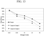
- a ratio of charge capacity at each C-rate to charge capacity after a constant current charge to an upper limit voltage of 4.25 V and a constant voltage charge to 0.05 C after at 25 °C was calculated and is shown in FIG. 13 .
- Example exhibits higher charge efficiency at all the C-rates than the comparative examples.
- a charge capacity of Example is less reduced even when the charge rate is increased.
- Example exhibits the same capacity at a faster rate or higher capacity even when charged for the same time.
- the improvement effect is much greater at high rates of 2 C and 3 C.
- the positive electrode active material of Example has primary particles having a radial structure of which many are small particles with a cross-sectional area of less than 0.1 ⁇ m 2 and exhibits a very small peak full width at half maximum (FWHM) of less than or equal to 0.125 of the (003) plane, a lithium ion diffusion coefficient is increased, and a high-rate charge capacity and a charge rate as well as initial charge/discharge efficiency are improved.
- FWHM full width at half maximum
- secondary particle 12 inner portion of secondary particle 13: primary particle 14: outer portion of secondary particle 100: rechargeable lithium battery 112: negative electrode 113: separator 114: positive electrode 120: battery case 140: sealing member
Landscapes
- Chemical & Material Sciences (AREA)
- Chemical Kinetics & Catalysis (AREA)
- Electrochemistry (AREA)
- General Chemical & Material Sciences (AREA)
- Inorganic Chemistry (AREA)
- Organic Chemistry (AREA)
- Engineering & Computer Science (AREA)
- Manufacturing & Machinery (AREA)
- Materials Engineering (AREA)
- Battery Electrode And Active Subsutance (AREA)
- Composite Materials (AREA)
Abstract
Provided are a positive electrode active material for a rechargeable lithium battery, and a rechargeable lithium battery including the same, the positive electrode active material including a lithium nickel-based composite oxide wherein the positive electrode active material is in a form of a secondary particle in which a plurality of primary particles are aggregated and at least a portion of the primary particles are radially arranged, in a cross-section of the secondary particle, a number ratio of primary particles having a cross-sectional area of less than about 0.1 µm2 is greater than or equal to about 65%, and a full width at half maximum (FWHM) of the peak corresponding to the (003) plane in the X-ray diffraction analysis for the positive electrode active material is less than or equal to about 0.125.
Description
- A positive electrode active material for a rechargeable lithium battery and a rechargeable lithium battery including the same are disclosed.
- A portable information device such as a cell phone, a laptop, a smart phone, and the like or an electric vehicle has used a rechargeable lithium battery having high energy density and easy portability as a driving power source. Recently, research has been actively conducted to use a rechargeable lithium battery with high energy density as a driving power source or power storage power source for hybrid or electric vehicles.
- As a positive electrode active material for a rechargeable lithium battery, a lithium nickel-based oxide such as a lithium nickel manganese cobalt composite oxide, a lithium cobalt oxide, or the like is used. When such a positive electrode active material is used, a long-term cycle-life of the positive electrode active material decreases, a resistance thereof increases, and capacity characteristics do not reach a satisfactory level due to cracks generated in the positive electrode active material as charging and discharging are repeated, and thus improvement is required.
- Provided are a positive electrode active material for a rechargeable lithium battery having high initial charge/discharge efficiency, high capacity realization, and high-rate charging capacity, which has improved high-speed charging characteristics, and a rechargeable lithium battery including the same.
- In an embodiment, a positive electrode active material for a rechargeable lithium battery includes a lithium nickel-based composite oxide, wherein the positive electrode active material is in a form of a secondary particle in which a plurality of primary particles are aggregated and at least a portion of the primary particles are radially arranged, in a cross-section of the secondary particles, a number ratio of the primary particles having a cross-sectional area of less than about 0.1 µm2 is greater than or equal to about 65%, and a full width at half maximum (FWHM) of the peak corresponding to the (003) plane in an X-ray diffraction analysis for the positive electrode active material is less than or equal to about 0.125.
- In another embodiment, a rechargeable lithium battery includes a positive electrode including the aforementioned positive electrode active material, a negative electrode, and an electrolyte.
- At least some of the above and other features of the invention are set out in the claims.
- The positive electrode active material and the rechargeable lithium battery including the same according to embodiments have high initial charge/discharge efficiency to realize high capacity, and have high-rate charge/discharge capacity, and thus have excellent high-speed charging characteristics.
-
-
FIG. 1 is a schematic view showing the shape of plate-shaped primary particles. -
FIG. 2 is a view for explaining the definition of a radial arrangement in secondary particles. -
FIG. 3 is a schematic view showing a cross-sectional structure of a secondary particle. -
FIG. 4 is a schematic view illustrating a rechargeable lithium battery according to an embodiment. -
FIG. 5 is a scanning electron microscope (SEM) image of a cross-section of the positive electrode active material according to Example which is cut with a focused ion beam (FIB) and an image of the primary particles contour-processed with an image program. -
FIG. 6 is a SEM image of a cross-section of the positive electrode active material according to Comparative Example 1 which is cut with the FIB and an image of the contour-processed primary particles. -
FIG. 7 is a SEM image of a cross-section of the positive electrode active material according to Comparative Example 2 which is cut with the FIB and an image of the contour-processed primary particles. -
FIG. 8 is a graph analyzing cross-sectional area distributions of the primary particles on the cross-sections of secondary particles of the positive electrode active materials according to Example and Comparative Examples 1 and 2. -
FIG. 9 is a graph showing a full width at half maximum of the (003) plane peak (FWHM003) and initial charge/discharge efficiency in the X-ray diffraction analysis of the positive electrode active materials of Example and Comparative Examples 1 to 3. -
FIG. 10 is a log graph of a lithium ion diffusion coefficient (DGITT) of the positive electrode active materials of Example and Comparative Examples 1 and 2 according to a voltage. -
FIG. 11 is a graph showing initial charge capacity, initial discharge capacity, and initial charge/discharge efficiency of the battery cells of Example and Comparative Examples 1 to 3. -
FIG. 12 is a graph showing charge capacity charged at 0.2 C, 0.5 C, 1.0 C, 2.0 C, and 3.0 C of the battery cells according to Example and Comparative Examples 1 and 2. -
FIG. 13 is a graph showing charge efficiency of the battery cells of Example and Comparative Examples 1 and 2 according to a C-rate. - Hereinafter, specific embodiments will be described in detail so that those of ordinary skill in the art can easily implement them. However, this disclosure may be embodied in many different forms and is not construed as limited to the example embodiments set forth herein.
- The terminology used herein is used to describe embodiments only, and is not intended to limit the present invention. The singular expression includes the plural expression unless the context clearly dictates otherwise.
- As used herein, "combination thereof" means a mixture, laminate, composite, copolymer, alloy, blend, reaction product, and the like of the constituents.
- Here, it should be understood that terms such as "comprises," "includes," or "have" are intended to designate the presence of an embodied feature, number, step, element, or a combination thereof, but it does not preclude the possibility of the presence or addition of one or more other features, numbers, steps, elements, or a combination thereof.
- In the drawings, the thickness of layers, films, panels, regions, etc., are exaggerated for clarity and like reference numerals designate like elements throughout the specification. It will be understood that when an element such as a layer, film, region, or substrate is referred to as being "on" another element, it can be directly on the other element or intervening elements may also be present. In contrast, when an element is referred to as being "directly on" another element, there are no intervening elements present.
- In addition, "layer" herein includes not only a shape formed on the whole surface when viewed from a plan view, but also a shape formed on a partial surface.
- In addition, the average particle diameter and the average size may be measured by a method well known to those skilled in the art, for example, may be measured by a particle size analyzer, or may be measured by a transmission electron microscopic image or a scanning electron microscopic image. Alternatively, it is possible to obtain an average particle diameter value by measuring a size using a dynamic light scattering method, performing data analysis, counting the number of particles for each particle size range, and calculating from this. Unless otherwise defined, the average particle diameter may mean the diameter (D50) of particles having a cumulative volume of 50 volume% in a particle size distribution as measured by a particle size analyzer.
- Here, "or" is not to be construed as an exclusive meaning, for example, "A or B", but is construed to include A, B, A+B, and the like.
- In an embodiment, a positive electrode active material includes a lithium nickel-based composite oxide wherein the positive electrode active material is in a form of a secondary particle in which a plurality of primary particles are aggregated and at least a portion of the primary particles are radially arranged, in a cross-section of the secondary particles, a number ratio of the primary particles having a cross-sectional area of less than about 0.1 µm2 is greater than or equal to about 65%, and a full width at half maximum (FWHM003) of the (003) plane peak in an X-ray diffraction analysis for the positive electrode active material is less than or equal to 0.125. The X-ray diffraction analysis may be performed using X'pert pro (PANalytical) using Cu Kα radiation (1.54056Å). The positive electrode active material may maximize initial charge/discharge efficiency due to structural characteristics, and may improve high-speed charging characteristics due to high high-rate charge/discharge capacity.
- The secondary particle may include plate-shaped primary particles.
FIG. 1 is a schematic view showing plate-shaped primary particles. Referring toFIG. 1 , the primary particles may have various detailed shapes while having a basic plate structure, such as (A) a polygonal nanoplate shape such as a hexagon, (B) a nano disk shape, and (C) a rectangular parallelepiped shape. - In
FIG. 1 , "a" means a length of a long axis of the primary particle, "b" means a length of a short axis, and "t" means a thickness. Here, the length (a) of the long axis means a maximum length with respect to the widest surface of the primary particle. The thickness (t) may be a maximum length of a surface that is approximately perpendicular to the widest surface of the primary particle. A direction containing the length (a) of the long axis and the length (b) of the short axis is defined as a plane direction, and a direction in which the thickness (t) is defined is defined as a thickness direction. - The thickness (t) of the primary particles may be smaller than the length (a) of the long axis and the length (b) of the short axis, which are lengths in the plane direction. The length (a) of the long axis among the lengths in the plane direction may be longer or the same as the length (b) of the short axis.
- In the positive electrode active material, at least a portion of the primary particles may have a radially arranged structure, and for example, long axes of the primary particles may be arranged in a radial direction.
FIG. 2 is a view for explaining the definition of a radial arrangement in a secondary particle according to an embodiment. In an embodiment, the radially arranged structure means that, as shown inFIG. 2 , the thickness (t) direction of the primary particles is perpendicular to or within an angle of about ±5 ° of perpendicular to the direction (R) from the secondary particle from the center of the secondary particle to the surface. - In this way, when at least a portion of the primary particles are radially arranged, since the secondary particles have lots of crystal planes, which transmit lithium to the outside, exposed to the surface and pores, which serve as a lithium diffusion passage, also exposed onto the surface, lithium diffusion may be improved, securing high initial efficiency and high capacity. In addition, the pores exposed to the surface of the secondary particles are directed toward a center of the secondary particles, which further promotes the lithium diffusion.
- Due to the radially arranged primary particles, uniform contraction and expansion of the positive electrode active material are possible when lithium is deintercalated and/or intercalated, and when lithium is deintercalated, more pores exist in the (001) direction, which is the direction in which the particles expand, so that they act as a buffer. Accordingly, probability of cracks occurring during contraction and expansion of the positive electrode active material is lowered, and internal pores further mitigate volume change, thereby reducing cracks generated between primary particles during charging and discharging. Accordingly, cycle-life characteristics of the rechargeable lithium battery may be improved and an increase in resistance may be reduced.
- In the positive electrode active material according to an embodiment, at least a portion of the primary particles are radially arranged, and simultaneously, in the cross-section of the secondary particles, the number of the primary particles having a cross-sectional area of less than about 0.1 µm2 satisfies a ratio of about 65% or more. In general, the lithium diffusion is much slower from the surface of the primary particles to the inner portion than along the boundaries between the primary particles on the surface of the secondary particles. Accordingly, in an embodiment, by reducing a size of the primary particles, slow diffusion within the primary particles is reduced, and fast diffusion at boundaries between the primary particles is increased.
- This positive electrode active material is advantageous in rate characteristics due to the easy lithium diffusion, and a rechargeable lithium battery manufactured by applying the same exhibits improved initial charge and discharge capacity and efficiency, obtaining an effect of securing high-rate charging capacity and shortening high-speed charging time.
- In a cross-section of the secondary particle of the positive electrode active material, a number ratio of the primary particles having a cross-sectional area of less than about 0.1 µm2 may be, for example, about 65% to about 90%, for example, about 70% to about 85%.
- In addition, in the cross-section of the secondary particle, a number ratio of the primary particles having a cross-sectional area of greater than about 0.3 µm2 may be less than or equal to about 5%, for example, about 0.1% to about 5%, or about 0.1% to about 4%.
- In the cross-section of the secondary particle, a number ratio of the primary particles having a cross-sectional area of about 0.1 µm2 to about 0.3 µm2 may be about 5% to about 30%, for example, about 11% to about 29.9%, or about 15% to about 29%.
- When the primary particles constituting the secondary particles of the positive electrode active material exhibit such a cross-sectional area distribution, the positive electrode active material has a reduced lithium ion diffusion distance, improving high-rate charge/discharge capacity, initial charge/discharge efficiency, and the like.
- The positive electrode active material satisfies the cross-sectional area distribution of the primary particles and simultaneously, a full width at half maximum of the peak corresponding to the (003) plane (FWHM003) of less than or equal to about 0.125 in the X-ray diffraction analysis. FWHM003 may be, for example, about 0.100 to about 0.125, about 0.110 to about 0.125, or about 0.100 to about 0.124. When the secondary particles of the positive electrode active material may be described as a structure in which the (003) planes of the primary particles are oriented perpendicular to the surface of the secondary particles, wherein the primary particles satisfy the aforementioned area distribution and also, a peak full width at half maximum (FWHM) of the (003) plane of less than or equal to about 0.125, the (003) planes are sufficiently aligned to maximize capacity, and simultaneously, easily move lithium ions, increasing initial charge/discharge efficiency and high-rate charge/discharge capacity, and in addition, cycle-life characteristics may be improved by minimizing a stress according to contraction and expansion of the positive electrode active material.
- The secondary particles of the positive electrode active material may include, for example, an inner portion having an irregular porous structure and an outer portion having a structure that has a least a portion of the primary particles radially arranged, that is, a radially arranged structure. The irregular porous structure is a structure having the primary particles and pores wherein a size, a shape, a position, and the like of the primary particles are irregular. In this inner portion, the primary particles may be arranged without regularity unlike the outer portion.
-
FIG. 3 is a schematic view showing a cross-sectional structure of the secondary particle of the positive electrode active material. Referring toFIG. 3 , thesecondary particles 11 of the positive electrode active material have anouter portion 14 having a structure in which the plate-shapedprimary particles 13 are arranged in a radial direction, and aninner portion 12 in which theprimary particles 13 are irregularly arranged. In theinner portion 12, there may be more empty spaces between the primary particles than the outer portion. In addition, a pore size and porosity of the inner portion may be large and irregular compared with those of the outer portion. InFIG. 3 , an arrow indicates a movement direction of lithium ions. - The positive electrode active material with this structure has a porous structure in the inner portion, so that a diffusion distance of lithium ions to the inner portion is reduced, and the pores may have an effect of alleviating volume changes between the primary particles occurring during the charge and discharge. In addition, in the positive electrode active material, the primary particles in the outer portion are radially arranged, so lithium ions may be easily intercalated into the surface, and a stress according to the volume changes may be minimized during the charge and discharge. This positive electrode active material may reduce resistance of a rechargeable lithium battery and improve charge and discharge efficiency and cycle-life characteristics thereof.
- In the secondary particles of the positive electrode active material, the inner portion may include pores with a larger size than those of the outer portion. For example, the pores in the inner portion may have a size of about 150 nm to about 1 µm, and the pores in the outer portion may have a size of less than about 150 nm. Here, in the outer portion, lithium ions may be easily intercalated, while in the inner portion, a lithium diffusion distance may be short, and there is an effect of alleviating the volume changes of the positive electrode active material during the charge and discharge. Here, the pores may have a size which is a diameter, when spherical or circular, and a length of a long axis when oval and the like, wherein the size is measured with a microscope such as SEM and the like.
- In addition, the secondary particles of the positive electrode active material may have open pores on the surface. The open pores may be pores of which a portion of walls are not closed, and the open pores on the surface may be connected to the outside and work as a passage through which a material comes in and out. These open pores may have a size of less than about 150 nm, for example, about 10 nm to about 148 nm. Since the primary particles in the outer portion of the secondary particles are radially arranged, the open pores on the surface may be in the form of facing a center from the surface of the secondary particles. The open pores may be formed to a depth of less than or equal to about 150 nm, for example, about 0.1 nm to about 100 nm, for example, about 1 nm to about 50 nm from the surface of the secondary particle. The size and depth of the open pores may be measured by the BJH (Barrett, Joyner and Halenda) method, which is a method derived through the adsorption or desorption content of nitrogen.
- The closed pores may exist in the inner portion of the secondary particle, and closed pores and/or open pores may exist in the outer portion. The closed pores may exclude or mostly exclude an electrolyte, while the open pores may include an electrolyte therein. The closed pores may be referred to as independent pores that are not connected to other pores since all of the walls of the pores are formed in a closed structure.
- In an embodiment, the inner portion to a total of the secondary particles may have a radius ratio of about 45% to about 65%, for example, about 45% to about 60%, about 50% to about 60%, or about 50% to about 55%. Here, initial charge/discharge efficiency and high temperature cycle-life characteristics may be improved.
- In addition, the outer portion to the total of the secondary particles may have a volume ratio of less than or equal to about 87%, for example, less than or equal to about 85%, about 80% to about 87%, or about 80% to about 85%. When the volume ratio of the outer portion of the secondary particles satisfies the ranges, initial charge/discharge efficiency and high temperature cycle-life characteristics may be further improved.
- Meanwhile, the average particle diameter (D50) of the secondary particle of the positive electrode active material may be about 5 µm to about 20 µm, for example, about 8 µm to about 18 µm, or about 10 µm to about 15 µm. Here, the positive electrode active material may realize high capacity and exhibit high initial charge/discharge efficiency and cycle-life characteristics. Here, the average particle diameter (D50) of the secondary particles may be measured in a laser diffraction method by dispersing the positive electrode active material with a dispersing agent in distilled water. Or, a scanning electron microscope and the like is used to take an electron microscope image of the surface or the cross-section of the secondary particles. Here, the electron microscope is used to measure about 30 particle diameters and thus obtain a particle distribution, wherein a particle diameter D50 at a cumulative volume of 50 volume% is obtained as the average particle diameter.
- The lithium nickel-based composite oxide may be represented by
Chemical Formula 1.
[Chemical Formula 1] Lia1Nix1M1 y1M2 1-x1-y1O2-zXz
- In
Chemical Formula 1, 0.9≤a1≤1.8, 0.3≤x1≤1, 0≤y1≤0.7, and 0≤z≤0.1, M1 and M2 are each independently at least one element selected from Al, B, Ba, Ca, Ce, Co, Cr, Fe, Mg, Mn, Mo, Nb, Si, Sr, Ti, V, W, and Zr, and X is at least one element selected from F, P, and S. - In
Chemical Formula 1, for example, 0.4≤x1≤1 and 0≤y1≤0.6, 0.5≤x1≤1 and 0≤y1≤0.5, 0.6≤x1≤1 and 0≤y1≤0.4, or 0.7≤x1≤1 and 0≤y1≤0.3, 0.8≤x1≤1 and 0≤y1≤0.2, or 0.9≤x1≤1 and 0≤y1≤0.1. - The lithium nickel-based composite oxide may be, for example, represented by
Chemical Formula 2.
[Chemical Formula 2] Lia2Nix2Coy2M3 1-x2-y2O2-zXz
- In
Chemical Formula 2, 0.9≤a2≤1.8, 0.3≤x2≤1, 0≤y2≤0.7, and 0≤z≤0.1, M3 is at least one element selected from Al, B, Ba, Ca, Ce, Cr, Fe, Mg, Mn, Mo, Nb, Si, Sr, Ti, V, W, and Zr, and X is at least one element selected from F, P, and S. - In
Chemical Formula 2, for example, 0.3≤x2≤0.99 and 0.01≤y2≤0.7, 0.4≤x2≤0.99 and 0.01≤y2≤0.6, 0.5≤x2≤0.99 and 0.01≤y2≤0.5, or 0.6≤x2≤0.99 and 0.01≤y2≤0.4, 0.7≤x2≤0.99 and 0.01≤y2≤0.3, 0.8≤x2≤0.99 and 0.01≤y2≤0.2, or 0.9≤x2≤0.99 and 0.01≤y2≤0.1. - The lithium nickel-based composite oxide may be, for example, represented by
Chemical Formula 3.
[Chemical Formula 3] Lia3Nix3Coy3M4 z3M5 1-x3-y3-z3O2-zXz
- In
Chemical Formula 3, 0.9≤a3≤1.8, 0.3≤x3≤0.98, 0.01≤y3≤0.69, 0.01≤z3≤0.69, and 0≤z≤0.1, M4 is at least one element selected from Al, and Mn, M5 is at least one element selected from B, Ba, Ca, Ce, Cr, Fe, Mg, Mo, Nb, Si, Sr, Ti, V, W, and Zr, and X is at least one element selected from F, P, and S. - In
Chemical Formula 3, for example, 0.4≤x3≤0.98, 0.01 ≤y3≤0.59, and 0.01 ≤z3≤0.59, may be 0.5≤x3≤0.98, 0.01 ≤y3≤0.49, and 0.01 ≤z3≤0.49, or 0.6≤x3≤0.98, 0.01 ≤y3≤0.39, and 0.01 ≤z3≤0.39, or 0.7≤x3≤0.98, 0.01 ≤y3≤0.29, and 0.01 ≤z3≤0.29, or 0.8≤x3≤0.98, 0.01 ≤y3≤0.19, and 0.01 ≤z3≤0.19, or 0.9≤x3≤0.98, 0.01 ≤y3≤0.09, and 0.01 ≤z3≤0.09. - In an embodiment, a method of preparing a positive electrode active material for a rechargeable lithium battery includes mixing a positive electrode active material precursor including a nickel-based composite hydroxide and a lithium raw material, and heat-treating the resultant.
- The positive electrode active material precursor may be prepared by a co-precipitation method. In other words, a nickel raw material and optionally, a metal raw material other than the nickel are mixed to prepare a composite metal raw material, and then, a complexing agent and a pH controlling agent are added thereto to control pH of the mixture and perform a co-precipitation reaction, preparing a nickel-based composite hydroxide having a desired composition.
- The complexing agent serves to control a reaction rate of the formation of a precipitate in the co-precipitation reaction, and may be, for example, ammonium hydroxide (NHOH), ammonium sulfate, or citric acid.
- The pH controlling agent may be, for example, sodium hydroxide (NaOH), sodium carbonate (Na2CO3), sodium oxalate (Na2C2O4), or the like. The pH of the mixture may be adjusted, for example, in the range of about 10 to about 13.
- The co-precipitation reaction may proceed in several steps, for example, 2 steps, 3 steps, or 4 steps. In each step, a concentration of the complexing agent, an input rate of the composite metal raw material, the pH range, a reaction temperature, reaction time, stirring power, and the like may be differently adjusted. Through these adjustments, a secondary particle-type positive electrode active material precursor, in which at least a portion of the primary particles are radially arranged, is prepared, and in addition, secondary particles having different internal and external shapes are prepared.
- In an embodiment, the positive electrode active material precursor including a nickel-based composite hydroxide is prepared through each first, second, and third step process of forming a core, an intermediate layer, and a shell.
- In the first step, a complex agent and a pH controlling agent are put in a reactor, and metal raw materials are added thereto and reacted, the complex agent may have a concentration of 0.1 M to 0.7 M, the input amount of the complex agent may be in a range of 6 mL/min to 12 mL/min, the metal raw materials may have concentrations of 0.1 M to 3.5 M, the input amounts of the metal raw materials may be in a range of 50 ml/min to 100 ml/min.
- In the second step, the metal raw materials and the complex agent are added to a resulting material of the first step reaction to control pH of the reaction mixture, and then, a reaction of the second step is performed, a concentration of the complex agent may be 0.3 M to 1.0 M, the input amount of the complex agent may be in a range of 8 ml/min to 15 ml/min, the metal raw materials may have concentrations of 0.1 M to 3.5 M, the input amounts of the metal raw materials may be in a range of 90 ml/min to 120 ml/min.
- In the third step, the input amounts and the concentrations of the metal raw materials and the complex agent may be increased in order to prevent a growth rate decrease of particles after reacting a reaction product from the second step for a predetermined time, the concentration of the complex agent may be in a range of 0.35 M to 1.0 M, the input amount of the complex agent may be in a range of 12 ml/min to 20 ml/min, the metal raw materials may have concentrations of 0.1 M to 3.5 M, the input amounts of the metal raw materials may be in a range of 120 ml/min to 150 ml/min.
- In the first step, the second step, and the third step, the pH of the reaction mixture may be adjusted in a range of 10 to 12.
- The nickel-based composite hydroxide may be, for example, represented by
Chemical Formula 11.
[Chemical Formula 11] Nix11M11 y11M12 1-x11-y11(OH)2
- In
Chemical Formula 11, 0.3≤x11≤1, 0≤y11≤0.7, and M11 and M12 are each independently selected from Al, B, Ba, Ca, Ce, Co, Cr, F, Fe, Mg, Mn, Mo, Nb, P, S, Si, Sr, Ti, V, W, Zr, and a combination thereof. - As a specific example, the nickel-based composite hydroxide may be represented by
Chemical Formula 12 orChemical Formula 13.
[Chemical Formula 12] Nix12COy12M13 1-x12-y12(OH)2
- In
Chemical Formula 12, 0.3≤x12≤1, 0≤y12≤0.7, and M13 is selected from Al, B, Ba, Ca, Ce, Cr, F, Fe, Mg, Mn, Mo, Nb, P, S, Si, Sr, Ti, V, W, Zr, and a combination thereof.
[Chemical Formula 13] Nix13Coy13M14 z13M15 1-x13-y13-z13(OH)2
- In
Chemical Formula 13, 0.3≤x13≤0.98, 0.01≤y13≤0.69, 0.01≤z13≤0.69, M14 is selected from Al, Mn, and a combination thereof, and M15 is selected from B, Ba, Ca, Ce, Cr, F, Fe, Mg, Mo, Nb, P, S, Si, Sr, Ti, V, W, Zr, and a combination thereof. - The average particle diameter (D50) of the positive electrode active material precursor may be, for example, about 5 µm to about 20 µm, or about 8 µm to about 18 µm. Here, the particle diameter of the secondary particle may be measured by an optical microscopic image such as a scanning electron microscope on the surface or cross-section of the secondary particle. A particle size distribution is obtained by measuring about 30 particle diameters through an optical microscope, and the D50 value, which is the particle diameter at a point where the cumulative volume is about 50 volume%, may be taken as the average particle diameter.
- The aforementioned positive electrode active material may be obtained by mixing the lithium raw material with the prepared positive electrode active material precursor and then performing heat-treatment.
- The lithium raw material may be, for example, Li2CO3, LiOH, a hydrate thereof, or a combination thereof, and may be mixed in a ratio of about 0.8 mole to about 1.8 mole, or about 0.9 mole to about 1.2 mole with respect to 1 mole of the nickel-based composite hydroxide.
- The heat-treatment may be performed, for example, at about 600 °C to about 900 °C or about 600 °C to about 800 °C.
- In an embodiment, the heat-treatment may include a temperature-raising step and a temperature-maintaining step, wherein the temperature-raising time may be longer than the temperature-maintaining time. For example, the temperature-raising time may be about 6 hours to about 16 hours, and the temperature-maintaining time may be about 1 hour to about 9 hours, wherein the temperature-raising time may be longer than the temperature-maintaining time.
- In the heat-treatment, the temperature-raising time may be, for example, about 6 hours to about 15 hours, about 6 hours to about 14 hours, about 6 hours to about 13 hours, or about 7 hours to about 12 hours, and the temperature-maintaining time may be about 2 hours to about 9 hours or about 3 hours to about 8 hours.
- In addition, a ratio of (temperature-raising time):(temperature-maintaining time) may be about 1.1:1 to about 10:1, for example, about 1.1:1 to about 8:1, about 1.1:1 to about 6:1, about 1.1:1 to about 5:1, or about 1.1:1 to about 4:1.
- In this way, the heat-treatment profile is adjusted to effectively control the primary particle cross-sectional area distribution and the peak full width at half maximum (FWHM) range of the (003) plane.
- The positive electrode for a rechargeable lithium battery may include a current collector and a positive electrode active material layer on the current collector. The positive electrode active material layer may include a positive electrode active material, and may further include a binder and/or a conductive material.
- The binder improves binding properties of positive electrode active material particles with one another and with a current collector. Examples thereof may be polyvinyl alcohol, carboxylmethyl cellulose, hydroxypropyl cellulose, diacetyl cellulose, polyvinylchloride, carboxylated polyvinylchloride, polyvinylfluoride, an ethylene oxide-containing polymer, polyvinylpyrrolidone, polyurethane, polytetrafluoroethylene, polyvinylidene fluoride, polyethylene, polypropylene, a styrene-butadiene rubber, an acrylated styrene-butadiene rubber, an epoxy resin, nylon, and the like, but are not limited thereto.
- The content of the binder in the positive electrode active material layer may be about 1 wt% to about 5 wt% based on the total weight of the positive electrode active material layer.
- The conductive material is included to provide electrode conductivity. Any electrically conductive material may be used as a conductive material unless it causes a chemical change. Examples of the conductive material may include a carbon-based material such as natural graphite, artificial graphite, carbon black, acetylene black, ketjen black, a carbon fiber, carbon nanotube, and the like; a metal-based material of a metal powder or a metal fiber including copper, nickel, aluminium, silver, and the like; a conductive polymer such as a polyphenylene derivative; or a mixture thereof.
- The content of the conductive material in the positive electrode active material layer may be about 1 wt% to about 5 wt% based on the total weight of the positive electrode active material layer.
- An aluminium foil may be used as the positive electrode current collector, but the present disclosure is not limited thereto.
- The negative electrode for a rechargeable lithium battery includes a current collector and a negative electrode active material layer on the current collector. The negative electrode active material layer includes a negative electrode active material and may further include a binder and/or a conductive material.
- The negative electrode active material may include a material that reversibly intercalates/deintercalates lithium ions, a lithium metal, a lithium metal alloy, a material capable of doping/dedoping lithium, or transition metal oxide.
- The material that reversibly intercalates/deintercalates lithium ions may include, for example crystalline carbon, amorphous carbon, or a combination thereof as a carbon-based negative electrode active material. The crystalline carbon may be non-shaped, or sheet, flake, spherical, or fiber shaped natural graphite or artificial graphite. The amorphous carbon may be a soft carbon, a hard carbon, a mesophase pitch carbonization product, calcined coke, and the like.
- The lithium metal alloy includes an alloy of lithium and a metal selected from Na, K, Rb, Cs, Fr, Be, Mg, Ca, Sr, Si, Sb, Pb, In, Zn, Ba, Ra, Ge, Al, and Sn.
- The material capable of doping/dedoping lithium may be a Si-based negative electrode active material or a Sn-based negative electrode active material. The Si-based negative electrode active material may include silicon, a silicon-carbon composite, SiOx (0 < x < 2), a Si-Q alloy (wherein Q is an alkali metal, an alkaline-earth metal, a
Group 13 element, aGroup 14 element, aGroup 15 element, a Group 16 element, a transition metal, a rare earth element, and a combination thereof, but not Si) and the Sn-based negative electrode active material may include Sn, SnO2, a Sn-R alloy (wherein R is an alkali metal, an alkaline-earth metal, aGroup 13 element, aGroup 14 element, aGroup 15 element, a Group 16 element, a transition metal, a rare earth element, and a combination thereof, but not Sn). At least one of these materials may be mixed with SiO2. The elements Q and R may be selected from Mg, Ca, Sr, Ba, Ra, Sc, Y, Ti, Zr, Hf, Rf, V, Nb, Ta, Db, Cr, Mo, W, Sg, Tc, Re, Bh, Fe, Pb, Ru, Os, Hs, Rh, Ir, Pd, Pt, Cu, Ag, Au, Zn, Cd, B, Al, Ga, Sn, In, TI, Ge, P, As, Sb, Bi, S, Se, Te, Po, and a combination thereof. - The silicon-carbon composite may be, for example, a silicon-carbon composite including a core including crystalline carbon and silicon particles and an amorphous carbon coating layer disposed on the surface of the core. The crystalline carbon may be artificial graphite, natural graphite, or a combination thereof. The amorphous carbon precursor may be a coal-based pitch, mesophase pitch, petroleum-based pitch, coal-based oil, petroleum-based heavy oil, or a polymer resin such as a phenol resin, a furan resin, or a polyimide resin. In this case, the content of silicon may be about 10 wt% to about 50 wt% based on the total weight of the silicon-carbon composite. In addition, the content of the crystalline carbon may be about 10 wt% to about 70 wt% based on the total weight of the silicon-carbon composite, and the content of the amorphous carbon may be about 20 wt% to about 40 wt% based on the total weight of the silicon-carbon composite. In addition, a thickness of the amorphous carbon coating layer may be about 5 nm to about 100 nm. An average particle diameter (D50) of the silicon particles may be about 10 nm to about 20 µm. The average particle diameter (D50) of the silicon particles may be preferably about 10 nm to about 200 nm. The silicon particles may exist in an oxidized form, and in this case, an atomic content ratio of Si:O in the silicon particles indicating a degree of oxidation may be a weight ratio of about 99:1 to about 33:67. The silicon particles may be SiOx particles, and in this case, the range of x in SiOx may be greater than about 0 and less than about 2. The average particle diameter (D50) is measured by a particle size analyzer and refers to a diameter of particles having a cumulative volume of 50 volume% in the particle size distribution.
- The Si-based negative electrode active material or Sn-based negative electrode active material may be mixed with the carbon-based negative electrode active material. When the Si-based negative electrode active material or Sn-based negative electrode active material and the carbon-based negative electrode active material are mixed and used, the mixing ratio may be a weight ratio of about 1:99 to about 90:10.
- In the negative electrode active material layer, the negative electrode active material may be included in an amount of about 95 wt% to about 99 wt% based on the total weight of the negative electrode active material layer.
- In an embodiment, the negative electrode active material layer further includes a binder, and may optionally further include a conductive material. The content of the binder in the negative electrode active material layer may be about 1 wt% to about 5 wt% based on the total weight of the negative electrode active material layer. In addition, when the conductive material is further included, the negative electrode active material layer may include about 90 wt% to about 98 wt% of the negative electrode active material, about 1 wt% to about 5 wt% of the binder, and about 1 wt% to about 5 wt% of the conductive material.
- The binder serves to well adhere the negative electrode active material particles to each other and also to adhere the negative electrode active material to the current collector. The binder may be a water-insoluble binder, a water-soluble binder, or a combination thereof.
- Examples of the water-insoluble binder include polyvinyl chloride, carboxylated polyvinyl chloride, polyvinyl fluoride, an ethylene oxide-containing polymer, an ethylene propylene copolymer, polystyrene, polyvinylpyrrolidone, polyurethane, polytetrafluoroethylene, polyvinylidene fluoride, polyethylene, polypropylene, polyamideimide, polyimide, or a combination thereof.
- The water-soluble binder may include a rubber binder or a polymer resin binder. The rubber binder may be selected from a styrene-butadiene rubber, an acrylated styrene-butadiene rubber, an acrylonitrile-butadiene rubber, an acrylic rubber, a butyl rubber, a fluororubber, and a combination thereof. The polymer resin binder may be selected from polyethylene oxide, polyvinylpyrrolidone, polyepichlorohydrin, polyphosphazene, polyacrylonitrile, an ethylene propylene diene copolymer, polyvinylpyridine, chlorosulfonated polyethylene, latex, a polyester resin, an acrylic resin, a phenol resin, an epoxy resin, polyvinyl alcohol, and a combination thereof.
- When a water-soluble binder is used as the negative electrode binder, a cellulose-based compound capable of imparting viscosity may be further included. As the cellulose-based compound, one or more of carboxymethyl cellulose, hydroxypropylmethyl cellulose, methyl cellulose, or alkali metal salts thereof may be mixed and used. As the alkali metal, Na, K or Li may be used. The amount of the thickener used may be about 0.1 parts by weight to about 3 parts by weight based on 100 parts by weight of the negative electrode active material.
- The conductive material is included to provide electrode conductivity. Any electrically conductive material may be used as a conductive material unless it causes a chemical change. Examples of the conductive material include a carbon-based material such as natural graphite, artificial graphite, carbon black, acetylene black, ketjen black, a carbon fiber, carbon nanotube, and the like; a metal-based material of a metal powder or a metal fiber including copper, nickel, aluminium, silver, and the like; a conductive polymer such as a polyphenylene derivative; or a mixture thereof.
- The negative electrode current collector may include one selected from a copper foil, a nickel foil, a stainless steel foil, a titanium foil, a nickel foam, a copper foam, a polymer substrate coated with a conductive metal, and a combination thereof.
- Another embodiment provides a rechargeable lithium battery including a positive electrode, a negative electrode, and an electrolyte.
- The rechargeable lithium battery may include, for example, a positive electrode, a negative electrode, a separator between the positive electrode and the negative electrode, and an electrolyte, wherein the electrolyte may be in the form of a liquid or a gel polymer. As another example, the rechargeable lithium battery may be an all-solid-state battery including a positive electrode, a negative electrode, and a solid electrolyte, or a semi-solid battery including a positive electrode, a negative electrode, and a semi-solid electrolyte. The semi-solid may mean a state including both a solid component and a liquid component, or a state in which most of the solid component is included but a portion of the liquid component is included. The all-solid-state battery and the semi-solid battery may not include a separator. The positive electrode active material according to an embodiment can realize very high charge/discharge efficiency and high temperature cycle-life while realizing a high capacity due to its shape, so it is suitable for application to the aforementioned types of batteries and exhibits excellent performance in each battery.
- As an example, a rechargeable lithium battery including a separator and a liquid electrolyte is described.
FIG. 4 is a schematic view illustrating a rechargeable lithium battery according to an embodiment. Referring toFIG. 4 , therechargeable lithium battery 100 according to an embodiment includes a battery cell including apositive electrode 114, anegative electrode 112 facing thepositive electrode 114, aseparator 113 between thepositive electrode 114 and thenegative electrode 112, an electrolyte for a rechargeable lithium battery impregnating thepositive electrode 114,negative electrode 112, andseparator 113, abattery case 120 containing the battery cell, and a sealingmember 140 sealing thebattery case 120. - The electrolyte includes a non-aqueous organic solvent and a lithium salt.
- The non-aqueous organic solvent serves as a medium for transmitting ions taking part in the electrochemical reaction of a battery. The non-aqueous organic solvent may include a carbonate-based, ester-based, ether-based, ketone-based, alcohol-based, or aprotic solvent. The carbonate-based solvent may include dimethyl carbonate (DMC), diethyl carbonate (DEC), dipropyl carbonate (DPC), methylpropyl carbonate (MPC), ethylpropyl carbonate (EPC), methylethyl carbonate (MEC), ethylene carbonate (EC), propylene carbonate (PC), butylene carbonate (BC), and the like. The ester-based solvent may include methyl acetate, ethyl acetate, n-propyl acetate, dimethylacetate, methylpropionate, ethylpropionate, γ-butyrolactone, decanolide, valerolactone, mevalonolactone, caprolactone, and the like. The ether-based solvent may include dibutyl ether, tetraglyme, diglyme, dimethoxyethane, 2-methyltetrahydrofuran, tetrahydrofuran, and the like and the ketone-based solvent may include cyclohexanone, and the like. In addition, the alcohol-based solvent may include ethanol, isopropyl alcohol, and the like and the aprotic solvent may include nitriles such as R-CN (wherein, R is a C2 to C20 linear, branched, or cyclic hydrocarbon group, and may include a double bond, an aromatic ring, or an ether bond), and the like, amides such as dimethyl formamide, and the like, dioxolanes such as 1,3-dioxolane, sulfolanes, and the like.
- The non-aqueous organic solvent may be used alone or in a mixture. When the non-aqueous organic solvent is used in a mixture, the mixture ratio may be controlled in accordance with a desirable battery performance.
- In addition, the carbonate-based solvent may include a mixture with a cyclic carbonate and a chain carbonate. In this case, when the cyclic carbonate and the chain carbonate are mixed in a volume ratio of about 1:1 to about 1:9, the electrolyte may exhibit excellent performance.
- The non-aqueous organic solvent may further include an aromatic hydrocarbon-based organic solvent in the carbonate-based solvent. In this case, the carbonate-based solvent and the aromatic hydrocarbon-based organic solvent may be mixed in a volume ratio of about 1:1 to about 30:1.
- As the aromatic hydrocarbon-based solvent, an aromatic hydrocarbon-based compound represented by Chemical Formula I may be used.

- In Chemical Formula I, R4 to R9 are the same or different and are selected from hydrogen, a halogen, a C1 to C10 alkyl group, a C1 to C10 haloalkyl group, and a combination thereof.
- Specific examples of the aromatic hydrocarbon-based solvent may be selected from benzene, fluorobenzene, 1,2-difluorobenzene, 1,3-difluorobenzene, 1,4-difluorobenzene, 1,2,3-trifluorobenzene, 1,2,4-trifluorobenzene, chlorobenzene, 1,2-dichlorobenzene, 1,3-dichlorobenzene, 1,4-dichlorobenzene, 1,2,3-trichlorobenzene, 1,2,4-trichlorobenzene, iodobenzene, 1,2-diiodobenzene, 1,3-diiodobenzene, 1,4-diiodobenzene, 1,2,3-triiodobenzene, 1,2,4-triiodobenzene, toluene, fluorotoluene, 2,3-difluorotoluene, 2,4-difluorotoluene, 2,5-difluorotoluene, 2,3,4-trifluorotoluene, 2,3,5-trifluorotoluene, chlorotoluene, 2,3-dichlorotoluene, 2,4-dichlorotoluene, 2,5-dichlorotoluene, 2,3,4-trichlorotoluene, 2,3,5-trichlorotoluene, iodotoluene, 2,3-diiodotoluene, 2,4-diiodotoluene, 2,5-diiodotoluene, 2,3,4-triiodotoluene, 2,3,5-triiodotoluene, xylene, and a combination thereof.
- The electrolyte may further include vinylene carbonate or an ethylene carbonate-based compound of Chemical Formula II in order to improve cycle-life of a battery.

- In Chemical Formula II, R10 and R11 are the same or different, and are selected from hydrogen, a halogen, a cyano group, a nitro group, and fluorinated C1 to C5 alkyl group, provided that at least one of R10 and R11 is selected from a halogen, a cyano group, a nitro group, and fluorinated C1 to C5 alkyl group, but both of R10 and R11 are not hydrogen.
- Examples of the ethylene carbonate-based compound may be difluoroethylene carbonate, chloroethylene carbonate, dichloroethylene carbonate, bromoethylene carbonate, dibromoethylene carbonate, nitroethylene carbonate, cyanoethylene carbonate, or fluoroethylene carbonate. The amount of the additive for improving cycle-life may be used within an appropriate range.
- The lithium salt dissolved in the non-aqueous organic solvent supplies lithium ions in a battery, enables a basic operation of a rechargeable lithium battery, and improves transportation of the lithium ions between positive and negative electrodes.
- Examples of the lithium salt include at least one supporting salt selected from LiPF6, LiBF4, LiSbF6, LiAsF6, LiN(SO2C2F5)2, Li(CF3SO2)2N, LiN(SO3C2F5)2, Li(FSO2)2N (lithium bis(fluorosulfonyl)imide: LiFSI), LiC4F9SO3, LiClO4, LiAlO2, LiAlCl4, LiPO2F2, LiN(CxF2x+1SO2)(CyF2y+1SO2) (wherein x and y are natural numbers, for example, an integer ranging from 1 to 20), lithium difluoro(bisoxalato) phosphate, LiCI, Lil, LiB(C2O4)2 (lithium bis(oxalato) borate, LiBOB), and lithium difluoro(oxalato)borate (LiDFOB).
- The lithium salt may be used in a concentration ranging from about 0.1 M to about 2.0 M. When the lithium salt is included at the above concentration range, an electrolyte may have excellent performance and lithium ion mobility due to optimal electrolyte conductivity and viscosity.
- The
separator 113 separates apositive electrode 114 and anegative electrode 112 and provides a transporting passage for lithium ions and may be any generally-used separator in a lithium ion battery. In other words, it may have low resistance to ion transport and excellent impregnation for an electrolyte. For example, theseparator 113 may include glass fiber, polyester, polyethylene, polypropylene, polytetrafluoroethylene, or a combination thereof, and may be in the form of a non-woven fabric or a woven fabric. For example, in a lithium ion battery, a polyolefin-based polymer separator such as polyethylene and polypropylene may be mainly used. In order to ensure the heat resistance or mechanical strength, a coated separator including a ceramic component or a polymer material may be used. Optionally, it may have a mono-layered or multilayered structure. - Rechargeable lithium batteries may be classified as lithium ion batteries, lithium ion polymer batteries, and lithium polymer batteries according to the presence of a separator and the kind of electrolyte used therein. The rechargeable lithium batteries may have a variety of shapes and sizes, and include cylindrical, prismatic, coin, or pouch-type batteries, and may be thin film batteries or may be rather bulky in size. Structures and manufacturing methods for lithium ion batteries pertaining to this disclosure are well known in the art.
- The rechargeable lithium battery according to an embodiment may be used in an electric vehicle (EV), a hybrid electric vehicle such as a plug-in hybrid electric vehicle (PHEV), and portable electronic device because it implements a high capacity and has excellent storage stability, cycle-life characteristics, and high rate characteristics at high temperatures.
- Hereinafter, examples of the present invention and comparative examples are described. It is to be understood, however, that the examples are for the purpose of illustration and are not to be construed as limiting the present invention.
- In the following co-precipitation method, nickel sulfate, cobalt sulfate, and aluminium nitrate were used as metal raw materials.
- First, ammonia water having a concentration of 0.40 M was put in a reactor. While metal raw materials and a complexing agent (NH4OH) were added thereto respectively at 85 ml/min and 10 ml/min at 50 °C under a stirring power of 2.5 kW/m3, a reaction was started.
- While NaOH was added thereto to maintain pH, the reaction was performed for 6 hours. As a result of the reaction, it was confirmed that the average sizes of the obtained core particles were in the range of about 6.5 µm to 7.5 µm, and the second step was performed as follows.
- The metal raw materials and the complexing agent were added thereto respectively at 107 ml/min and 15 ml/min, while the reaction temperature was maintained at 50 °C, so that a concentration of the complexing agent was adjusted to be 0.45 M. While adding NaOH thereto in order to maintain pH, the reaction was performed for 18 hours. At this time, the stirring power was lowered to 2.0 kW/m3, which was lower than the first step, and the reaction proceeded. By performing this reaction, it was confirmed that the average sizes of the product particles containing the core and the intermediate layer were 11.5 µm to 12 µm, and the third step was performed as follows.
- While maintaining the reaction temperature of 50 °C, the metal raw material and the complexing agent were added at the rates of 142 ml/min and 19 ml/min, respectively, so that the concentration of the complexing agent was maintained the same as in the second step. While adding NaOH thereto in order to maintain pH, the reaction was performed for 10 hours. At this time, the stirring power was lowered to 1.0 kW/m3, which was lower than in the second step, and the reaction proceeded.
- After washing the resultant, the washed resultant was dried with hot air at about 150 °C for 24 hours to obtain nickel-based hydroxide (Ni0.945Co0.04Al0.015(OH)2), which is a positive electrode active material precursor.
- 100 parts by mole of LiOH was mixed with 100 moles of the obtained nickel-based composite hydroxide, a temperature was raised to 700 °C for 8 hours in an oxygen atmosphere, and heat-treatment was performed for 7 hours to prepare a final positive electrode active material, a nickel-based composite oxide (LiNi0.945Co0.04Al0.015O2).
- As such, it was confirmed that the final positive electrode active material prepared in Example was in a form of a secondary particle including an inner portion having an irregular porous structure and an outer portion having a radially arranged structure, and the peak full width at half maximum (FWHM) of the (003) plane in X-ray diffraction analysis was 0.1208.
- 96 wt% of the obtained positive electrode active material, 2 wt% of polyvinylidene fluoride, 2 wt% of carbon nanotube, and N-methylpyrrolidone as a solvent were mixed in a mixer to prepare slurry for a positive electrode active material layer. The slurry was coated on an aluminium foil into an electrode plate and then, dried at 135 °C for at least 3 hours, roll-pressed, and vacuum-dried, manufacturing a positive electrode.
- The positive electrode and a lithium metal counter electrode were used to manufacture a coin half-cell. Between the positive electrode and the lithium metal counter electrode, a separator formed of a porous polyethylene film (thickness: about 16 µm) was interposed, and an electrolyte solution was injected thereinto. The electrolyte solution was prepared by mixing ethylene carbonate (EC) and ethylmethyl carbonate (EMC) in a volume ratio of 3:5 and dissolving 1.1 M LiPF6 in the mixed solvent.
- Nickel sulfate, cobalt sulfate, and aluminium nitrate were dissolved in distilled water at a mole ratio of 94.5:4:1.5 to prepare a metal raw material mixed solution. A dilute ammonia water (NH4OH) solution and sodium hydroxide (NaOH) as a precipitant were prepared to form a complex compound.
- After adding the dilute ammonia water solution to the continuous reactor, the metal raw material mixed solution was continuously added, and sodium hydroxide was added to maintain the pH inside the reactor. The reaction proceeded slowly for about 80 hours, and when the reaction was stabilized, the product that overflowed was collected and the drying process proceeded.
- Accordingly, a nickel-based composite hydroxide (Ni0.945Co0.04Al0.015(OH)2) in the form of a secondary particle in which primary particles were aggregated was prepared.
- 100 parts by mole of LiOH was mixed with 100 moles of the obtained nickel-based composite hydroxide, a temperature was raised to 700 °C for 8 hours in an oxygen atmosphere, and heat-treatment was performed for 7 hours to prepare a radial-type nickel-based composite oxide, LiNi0.945Co0.04Al0.015O2.
- In the X-ray diffraction analysis of the positive electrode active material obtained in Comparative Example 1, the peak full width at half maximum (FWHM) of the (003) plane was confirmed to be 0.1292. The positive electrode active material of Comparative Example 1 had a radial structure and a peak full width at half maximum (FWHM) of the (003) plane exceeded 0.125. It was also the case that the ratio of large primary particles was large.
- Thereafter, a positive electrode and a battery cell were manufactured in the same manner as in Example.
- In the following co-precipitation method, nickel sulfate, cobalt sulfate, and aluminium nitrate were used as metal raw materials.
- First, ammonia water having a concentration of 0.35 M was put in a reactor. While metal raw materials and a complexing agent were added thereto respectively at 85 ml/min and 9 ml/min at 50 °C under a stirring power of 2.5 kW/m3, a reaction was started. While NaOH was added thereto to maintain pH, the reaction was performed for 6 hours. As a result of the reaction, it was confirmed that the average sizes of the obtained core particles were in the range of about 5.5 µm to 6.5 µm, and the second step was performed as follows.
- The metal raw materials and the complexing agent were added thereto respectively at 107 ml/min and 15 ml/min, while the reaction temperature was maintained at 50 °C, so that the complexing agent adjusted a concentration of 0.45 M. While adding NaOH thereto in order to maintain pH, the reaction was performed for 18 hours. At this time, the stirring power was lowered to 1.5 kW/m3, which was lower than the first step, and the reaction proceeded. By performing this reaction, it was confirmed that the average sizes of the product particles containing the core and the intermediate layer were 11.5 µm to 12 µm, and the third step was performed as follows.
- While maintaining the reaction temperature of 50 °C, the metal raw material and the complexing agent were added at the rates of 142 ml/min and 19 ml/min, respectively, so that the concentration of the complexing agent was maintained the same as in the second step. While adding NaOH thereto in order to maintain pH, the reaction was performed for 10 hours. At this time, the stirring power was lowered to 1.0 kW/m3, which was lower than in the second step, and the reaction proceeded.
- After washing the resultant, the washed resultant was dried with hot air at about 150 °C for 24 hours to obtain nickel-based hydroxide (Ni0.945Co0.04Al0.015(OH)2), which is positive electrode active material precursor.
- In the preparation of the positive electrode active material, a positive electrode active material precursor, a positive electrode active material, a positive electrode, and a battery cell were prepared according to the same method as in Example, except that the nickel-based composite hydroxide and LiOH were mixed, then the temperature was raised to 700 °C for 5 hours, and heat-treatment is performed for 10 hours.
- In the X-ray diffraction analysis of the positive electrode active material obtained in Comparative Example 2, the peak full width at half maximum (FWHM) of the (003) plane was confirmed to be 0.136. The positive electrode active material of Comparative Example 2 had a radial structure and a peak full width at half maximum (FWHM) of the (003) plane exceeded 0.125. It was also a case where a proportion of large primary particles was small.
- Nickel sulfate, cobalt sulfate, and aluminium nitrate were dissolved in distilled water at a mole ratio of 94.5:4:1.5 to prepare a metal raw material mixed solution. A dilute ammonia water (NH4OH) solution and sodium hydroxide (NaOH) as a precipitant were prepared to form a complex compound.
- After adding the dilute ammonia water solution to the continuous reactor, the metal raw material mixed solution was continuously added, and sodium hydroxide was added to maintain the pH inside the reactor. The reaction proceeded slowly for about 80 hours, and when the reaction was stabilized, the product that overflowed was collected and the drying process proceeded.
- Accordingly, a nickel-based composite hydroxide (Ni0.945Co0.04Al0.015(OH)2) in a form of a secondary particle in which primary particles were not radially arranged was prepared.
- 100 parts by mole of LiOH was mixed with 100 moles of the obtained nickel-based composite hydroxide, a temperature was raised to 700 °C for 5 hours in an oxygen atmosphere, and heat-treatment was performed for 10 hours to prepare a non-radial nickel-based composite oxide, LiNi0.945Co0.04Al0.015O2.
- In the X-ray diffraction analysis of the positive electrode active material obtained in Comparative Example 3, the peak full width at half maximum (FWHM) of the (003) plane was confirmed to be 0.125. That is, the positive electrode active material of Comparative Example 3 had a peak full width at half maximum (FWHM) of 0.125 or less, but had a non-radial structure.
- Thereafter, a positive electrode and a battery cell were manufactured in the same manner as in Example.
-
FIG. 5 is a scanning electron microscope (SEM) image of a cross-section of the positive electrode active material according to Example which is cut with a focused ion beam (FIB) and an image obtained by inputting the image to a computer and contouring the primary particles with an Image J program.FIG. 6 is a cross-section SEM image of the positive electrode active material of Comparative Example 1 and an image obtained by contour-processing the primary particles, andFIG. 7 is a cross-section SEM image of the positive electrode active material of Comparative Example 2 and an image obtained by contour-processing the primary particle. - Referring to
FIGS. 5 to 7 , the positive electrode active material of Example is secondary particles including an inner portion having an irregular porous structure and an outer portion having a radial structure; in the positive electrode active material of Comparative Example 1, a portion of the primary particles are radially arranged, but there are many large primary particles; and in the positive electrode active material of Comparative Example 2, a portion of the primary particles are radially arranged, but in the inner portion, a pore layer is not developed. - The positive electrode active materials according to Example and Comparative Examples 1 and 2 were measured regarding a cross-sectional area distribution of primary particles by contour-processing the primary particle in the FIB cross-section SEM images, as shown in
FIGS. 5 to 7 , and measuring cross-sectional areas of the primary particles with an Image J program.FIG. 8 is a graph analyzing the cross-sectional area distribution of primary particles, wherein a black bar graph represents a ratio of the number of primary particles having a cross-sectional area of smaller than 0.1 µm2, a hatched bar graph represents a ratio of the number of primary particles having a cross-sectional area of 0.1 µm2 to 0.3 µm2, and a dotted line graph represents a ratio of the number of large primary particles having a cross-sectional area of larger than 0.3 µm2. - Referring to
FIG. 8 , the ratio of the number of primary particles having a cross-sectional area of less than 0.1 µm2 is 37% in Comparative Example 1 and 60% in Comparative Example 2 but 77% in Example, which is much higher than the comparative examples and satisfies greater than or equal to 65%. In addition, the ratio of the number of primary particles having a cross-sectional area of greater than 0.3 µm2 is about 33% in Comparative Example 1 and about 10% in Comparative Example 2 but about 2% in Example, which is much lower than the comparative examples. - X-ray diffraction analysis was performed on the positive electrode active materials according to Example and Comparative Examples 1 to 3 to take a peak full width at half maximum (FWHM) of the (003) plane, and the results are shown in
FIG. 9 . InFIG. 9 , the bar graph shows a peak full width at half maximum (FWHM) of the (003) plane, and the dotted line graph shows initial charge/discharge efficiency described later. - Referring to
FIG. 9 , Comparative Examples 1 and 2 exhibit a peak full width at half maximum (FWHM) of greater than 0.125 of the (003) plane, but Comparative Example 3 and Example satisfy less than or equal to 0.125. - For the positive electrode active materials according to Example and Comparative Examples 1 and 2, a log graph of a lithium ion diffusion coefficient (DGITT) according to a charging voltage was derived by using Galvanostatic Intermittent Titration Technique (GITT), and the results are shown in
FIG. 10 . - Referring to
FIG. 10 , Example exhibits a higher lithium ion diffusion coefficient than Comparative Examples 1 and 2 and thus, is advantageous for kinetically high-rate charging. - The battery cells according to Example and Comparative Examples 1 to 3 were charged to an upper limit voltage of 4.25 V at a constant current of 0.2 C at 25 °C and discharged to a discharge cut-off voltage of 3.0 V at a constant current of 0.2 C to perform initial charge and discharge. In
FIG. 11 , the bar graph exhibits initial charge capacity and initial discharge capacity, and the dotted line graph exhibits a ratio of the initial discharge capacity to the initial charge capacity, which is initial efficiency. In addition, inFIG. 9 , the initial efficiency is additionally marked by a dotted line graph. - Referring to
FIG. 11 , Example exhibits high initial charge capacity and initial discharge capacity and much improved initial charge/discharge efficiency, compared with the comparative examples. The positive electrode active material of Example has many primary particles having a radially-arranged structure, a small cross-sectional area, for example, a cross-sectional area of less than 0.1 µm2 and simultaneously, a very small peak full width at half maximum (FWHM) of less than or equal to 0.125 of the (003) plane and thus low diffusion resistance of lithium ions, that is, a high diffusion coefficient of lithium and thereby, improved initial charge and discharge capacity and initial charge/discharge efficiency. It can be seen that the diffusion resistance of lithium ions is low, that is, the diffusion coefficient of lithium is increased, and thus initial charge/discharge capacity and initial charge/discharge efficiency are improved. - Comparative Example 3 is a case of applying a positive electrode active material having a peak full width at half maximum (FWHM) of 0.125 of the (003) plane but not having the radial structure used in an embodiment, and referring to
FIG. 11 , initial charge and discharge capacity is deteriorated, and initial charge/discharge efficiency is also much deteriorated, compared with the example. - The battery cells according to Example and Comparative Examples 1 and 2 were constant current-charged to an upper limit voltage of 4.25 V at 25 °C and constant current-discharged to a cut-off voltage of 3.0 V at a constant current of 0.2 C, wherein charge capacity was measured at each C-rate set to 0.2 C, 0.5 C, 1.0 C, 2.0 C, and 3.0 C, and the results are shown in
FIG. 12 . In addition, a ratio of charge capacity at each C-rate to charge capacity after a constant current charge to an upper limit voltage of 4.25 V and a constant voltage charge to 0.05 C after at 25 °C was calculated and is shown inFIG. 13 . - Referring to
FIG. 12 , Example exhibits higher charge efficiency at all the C-rates than the comparative examples. Referring toFIG. 13 , a charge capacity of Example is less reduced even when the charge rate is increased. In other words, Example exhibits the same capacity at a faster rate or higher capacity even when charged for the same time. Particularly, the improvement effect is much greater at high rates of 2 C and 3 C. - As the positive electrode active material of Example has primary particles having a radial structure of which many are small particles with a cross-sectional area of less than 0.1 µm2 and exhibits a very small peak full width at half maximum (FWHM) of less than or equal to 0.125 of the (003) plane, a lithium ion diffusion coefficient is increased, and a high-rate charge capacity and a charge rate as well as initial charge/discharge efficiency are improved.
- Although preferred embodiments have been described in detail above, the scope of the present invention is not limited thereto. In addition, it should be understood that various modifications and improvements by those skilled in the art using the basic concept defined in the claims also fall within the scope of the present invention.
-
11: secondary particle 12: inner portion of secondary particle 13: primary particle 14: outer portion of secondary particle 100: rechargeable lithium battery 112: negative electrode 113: separator 114: positive electrode 120: battery case 140: sealing member
Claims (9)
- A positive electrode active material for a rechargeable lithium battery, comprisinga lithium nickel-based composite oxide wherein the positive electrode active material is in a form of a secondary particle in which a plurality of primary particles are aggregated and at least a portion of the primary particles are radially arranged,in a cross-section of the secondary particles, a number ratio of the primary particles having a cross-sectional area of less than 0.1 µm2 is greater than or equal to 65%, anda full width at half maximum (FWHM) of the peak corresponding to the (003) plane in an X-ray diffraction analysis for the positive electrode active material is less than or equal to 0.125.
- The positive electrode active material of claim 1, wherein
in the cross-section of the secondary particle, the number ratio of the primary particles having a cross-sectional area of less than 0.1 µm2 is 65% to 90%. - The positive electrode active material of claim 1 or claim 2, wherein
in a cross-section of the secondary particle, a number ratio of the primary particles having a cross-sectional area of greater than 0.3 µm2 is less than or equal to 5%. - The positive electrode active material of any one of claims 1 to 3, wherein
in a cross-section of the secondary particle, a number ratio of the primary particles having a cross-sectional area of 0.1 µm2 to 0.3 µm2 is 5% to 30%. - The positive electrode active material of any one of claims 1 to 4, wherein
a full width at half maximum of the peak corresponding to the (003) plane in an X-ray diffraction analysis for the positive electrode active material is 0.100 to 0.125. - The positive electrode active material of any one of claims 1 to 5, wherein
the secondary particle includes an inner portion in which primary particles and pores are irregularly arranged, and an outer portion in which at least a portion of the primary particles are radially arranged wherein the outer portion is a region surrounding the inner portion. - The positive electrode active material of any one of claims 1 to 6, wherein
an average particle diameter (D50) of the secondary particle is 5 µm to 20 µm. - The positive electrode active material of any one of claims 1 to 7, whereinthe lithium nickel-based composite oxide is represented by Chemical Formula 1:
[Chemical Formula 1] Lia1Nix1M1 y1M2 1-x1-y1O2-zXz
wherein, in Chemical Formula 1, 0.9≤a1≤1.8, 0.3≤x1≤1, 0≤y1≤0.7, and 0≤z≤0.1, M1 and M2 are each independently at least one element selected from Al, B, Ba, Ca, Ce, Co, Cr, Fe, Mg, Mn, Mo, Nb, Si, Sr, Ti, V, W, and Zr, and X is at least one element selected from F, P, and S. - A rechargeable lithium battery, comprisinga positive electrode including the positive electrode active material of any one of claims 1 to 8,a negative electrode, andan electrolyte.
Applications Claiming Priority (1)
| Application Number | Priority Date | Filing Date | Title |
|---|---|---|---|
| KR1020220036319A KR102767262B1 (en) | 2022-03-23 | 2022-03-23 | Positive electrode active material for rechargeable lithium battery and rechargeable lithium battery |
Publications (1)
| Publication Number | Publication Date |
|---|---|
| EP4249438A1 true EP4249438A1 (en) | 2023-09-27 |
Family
ID=84358106
Family Applications (1)
| Application Number | Title | Priority Date | Filing Date |
|---|---|---|---|
| EP22207609.3A Pending EP4249438A1 (en) | 2022-03-23 | 2022-11-15 | Positive electrode active material for rechargeable lithium battery and rechargeable lithium battery |
Country Status (4)
| Country | Link |
|---|---|
| US (1) | US20230327101A1 (en) |
| EP (1) | EP4249438A1 (en) |
| KR (2) | KR102767262B1 (en) |
| CN (1) | CN116805682A (en) |
Families Citing this family (1)
| Publication number | Priority date | Publication date | Assignee | Title |
|---|---|---|---|---|
| CN121394518A (en) * | 2025-05-16 | 2026-01-23 | 宁德时代新能源科技股份有限公司 | Secondary batteries and electrical devices |
Citations (1)
| Publication number | Priority date | Publication date | Assignee | Title |
|---|---|---|---|---|
| US20180026268A1 (en) * | 2016-07-20 | 2018-01-25 | Samsung Sdi Co., Ltd. | Nickel-based active material for lithium secondary battery, method of preparing the same, and lithium secondary battery including positive electrode including the nickel-based active material |
Family Cites Families (15)
| Publication number | Priority date | Publication date | Assignee | Title |
|---|---|---|---|---|
| US6045771A (en) * | 1995-11-24 | 2000-04-04 | Fuji Chemical Industry Co., Ltd. | Lithium-nickel complex oxide, a process for preparing the same and a positive electrode active material for a secondary battery |
| WO2003069702A1 (en) * | 2002-02-15 | 2003-08-21 | Seimi Chemical Co., Ltd. | Particulate positive electrode active material for lithium secondary cell |
| KR101729174B1 (en) * | 2009-08-21 | 2017-04-21 | 가부시키가이샤 지에스 유아사 | Lithium secondary battery active material, lithium secondary battery electrode, lithium secondary battery, and method for manufacturing same |
| KR20110136002A (en) * | 2010-06-13 | 2011-12-21 | 삼성에스디아이 주식회사 | A lithium secondary battery comprising a cathode active material precursor for a lithium secondary battery and a cathode active material and a cathode active material for a lithium secondary battery using the same |
| US9559351B2 (en) * | 2011-03-31 | 2017-01-31 | Sumitomo Metal Mining Co., Ltd. | Nickel composite hydroxide particles and nonaqueous electrolyte secondary battery |
| JP4894969B1 (en) * | 2011-06-07 | 2012-03-14 | 住友金属鉱山株式会社 | Nickel-manganese composite hydroxide particles and production method thereof, positive electrode active material for non-aqueous electrolyte secondary battery and production method thereof, and non-aqueous electrolyte secondary battery |
| JP5316726B2 (en) * | 2011-06-07 | 2013-10-16 | 住友金属鉱山株式会社 | Nickel composite hydroxide and production method thereof, positive electrode active material for non-aqueous electrolyte secondary battery, production method thereof, and non-aqueous electrolyte secondary battery |
| KR101718057B1 (en) * | 2012-08-02 | 2017-03-20 | 삼성에스디아이 주식회사 | Positive active material, and positive electrode and lithium battery containing the material |
| KR101713454B1 (en) * | 2012-08-28 | 2017-03-07 | 스미토모 긴조쿠 고잔 가부시키가이샤 | Method for producing positive electrode active material for nonaqueous electrolyte secondary batteries, positive electrode active material for nonaqueous electrolyte secondary batteries, and nonaqueous electrolyte secondary battery using same |
| KR101785262B1 (en) * | 2013-07-08 | 2017-10-16 | 삼성에스디아이 주식회사 | Positive electrode active material, preparing method thereof, positive electrode including the same, and lithium secondary battery employing the positive electrode |
| JP6435093B2 (en) * | 2013-11-22 | 2018-12-05 | 三星エスディアイ株式会社SAMSUNG SDI Co., LTD. | Positive electrode active material and lithium ion secondary battery |
| KR102295366B1 (en) * | 2016-07-20 | 2021-08-31 | 삼성에스디아이 주식회사 | Nickel-based active material for lithium secondary battery, preparing method thereof, and lithium secondary battery comprising positive electrode including nickel-based active material |
| CN109428076B (en) * | 2017-09-04 | 2023-04-11 | 三星电子株式会社 | Positive active material precursor, positive active material, method for producing positive active material, positive electrode, and lithium battery |
| HUE069404T2 (en) * | 2017-12-04 | 2025-03-28 | Samsung Sdi Co Ltd | Positive active material for rechargeable lithium battery, preparing method thereof and rechargeable lithium battery comprising positive electrode including positive active material |
| EP3699986B1 (en) * | 2019-02-20 | 2025-06-11 | Nichia Corporation | Positive-electrode active material for nonaqueous secondary battery, and method for manufacturing same |
-
2022
- 2022-03-23 KR KR1020220036319A patent/KR102767262B1/en active Active
- 2022-11-15 EP EP22207609.3A patent/EP4249438A1/en active Pending
- 2022-11-17 US US17/989,547 patent/US20230327101A1/en active Pending
- 2022-11-23 CN CN202211476529.1A patent/CN116805682A/en active Pending
-
2025
- 2025-02-07 KR KR1020250016223A patent/KR20250024955A/en active Pending
Patent Citations (1)
| Publication number | Priority date | Publication date | Assignee | Title |
|---|---|---|---|---|
| US20180026268A1 (en) * | 2016-07-20 | 2018-01-25 | Samsung Sdi Co., Ltd. | Nickel-based active material for lithium secondary battery, method of preparing the same, and lithium secondary battery including positive electrode including the nickel-based active material |
Non-Patent Citations (1)
| Title |
|---|
| LI XIANG ET AL: "Comprehensive study of tantalum doping on morphology, structure, and electrochemical performance of Ni-rich cathode materials", ELECTROCHIMICA ACTA, ELSEVIER, AMSTERDAM, NL, vol. 403, 28 November 2021 (2021-11-28), XP086917909, ISSN: 0013-4686, [retrieved on 20211128], DOI: 10.1016/J.ELECTACTA.2021.139653 * |
Also Published As
| Publication number | Publication date |
|---|---|
| CN116805682A (en) | 2023-09-26 |
| US20230327101A1 (en) | 2023-10-12 |
| KR102767262B1 (en) | 2025-02-11 |
| KR20230138355A (en) | 2023-10-05 |
| KR20250024955A (en) | 2025-02-20 |
Similar Documents
| Publication | Publication Date | Title |
|---|---|---|
| KR102818646B1 (en) | Positive active material for rechargeable lithium battery, preparing method thereof and rechargeable lithium battery including the same | |
| KR102853967B1 (en) | Positive active material for rechargeable lithium battery, preparing method thereof and rechargeable lithium battery including the same | |
| US11777075B2 (en) | Positive active material for rechargeable lithium battery, preparing method thereof and rechargeable lithium battery comprising positive electrode including positive active material | |
| US20250219056A1 (en) | Positive electrode active material for rechargeable lithium battery, method of preparing the same, and rechargeable lithium battery | |
| US12388077B2 (en) | Positive electrode active material for rechargeable lithium battery, method of preparing the same, and rechargeable lithium battery | |
| KR20230025342A (en) | Positive active material for rechargeable lithium battery, preparing method thereof and rechargeable lithium battery including the same | |
| KR20260007162A (en) | Positive active material for rechargeable lithium battery, preparing method thereof and rechargeable lithium battery including the same | |
| KR20250165299A (en) | Positive active material for rechargeable lithium battery, preparing method thereof and rechargeable lithium battery including the same | |
| KR20250050848A (en) | Positive active material for rechargeable lithium battery and rechargeable lithium battery including the same | |
| KR102918044B1 (en) | Positive active material for rechargeable lithium batteries, preparation method thereof, and rechargeable lithium batteries | |
| KR20240094715A (en) | Positive electrode for rechargeable lithium battery, and rechargeable lithium battery including the same | |
| KR20250024955A (en) | Positive electrode active material for rechargeable lithium battery and rechargeable lithium battery | |
| US12355078B2 (en) | Rechargeable lithium battery | |
| KR20140118860A (en) | Positive active material for rechargeable lithium battery, method of preparing the same, and rechargeable lithium battery including the same | |
| EP4159688A2 (en) | Positive electrode active material for rechargeable lithium battery, method of preparing the same, and rechargeable lithium battery | |
| KR20240085142A (en) | Positive active material for rechargeable lithium battery, preparing method thereof and rechargeable lithium battery including the same |
Legal Events
| Date | Code | Title | Description |
|---|---|---|---|
| PUAI | Public reference made under article 153(3) epc to a published international application that has entered the european phase |
Free format text: ORIGINAL CODE: 0009012 |
|
| STAA | Information on the status of an ep patent application or granted ep patent |
Free format text: STATUS: REQUEST FOR EXAMINATION WAS MADE |
|
| 17P | Request for examination filed |
Effective date: 20221115 |
|
| AK | Designated contracting states |
Kind code of ref document: A1 Designated state(s): AL AT BE BG CH CY CZ DE DK EE ES FI FR GB GR HR HU IE IS IT LI LT LU LV MC ME MK MT NL NO PL PT RO RS SE SI SK SM TR |