EP4249392A2 - Splash guard for vented containers - Google Patents
Splash guard for vented containers Download PDFInfo
- Publication number
- EP4249392A2 EP4249392A2 EP23181698.4A EP23181698A EP4249392A2 EP 4249392 A2 EP4249392 A2 EP 4249392A2 EP 23181698 A EP23181698 A EP 23181698A EP 4249392 A2 EP4249392 A2 EP 4249392A2
- Authority
- EP
- European Patent Office
- Prior art keywords
- perimeter
- splash guard
- fitment
- container
- vent membrane
- Prior art date
- Legal status (The legal status is an assumption and is not a legal conclusion. Google has not performed a legal analysis and makes no representation as to the accuracy of the status listed.)
- Withdrawn
Links
- 239000012528 membrane Substances 0.000 claims abstract description 47
- 239000007788 liquid Substances 0.000 claims description 42
- -1 polyethylene Polymers 0.000 claims description 9
- 239000004698 Polyethylene Substances 0.000 claims description 6
- 229920000573 polyethylene Polymers 0.000 claims description 6
- 238000013022 venting Methods 0.000 claims description 4
- 230000000903 blocking effect Effects 0.000 claims description 3
- 239000000126 substance Substances 0.000 abstract description 20
- 239000000463 material Substances 0.000 abstract description 7
- 238000012546 transfer Methods 0.000 abstract description 6
- 238000004519 manufacturing process Methods 0.000 abstract description 5
- 238000004321 preservation Methods 0.000 abstract description 2
- 239000000047 product Substances 0.000 description 20
- 238000000034 method Methods 0.000 description 12
- 239000007789 gas Substances 0.000 description 8
- 238000004140 cleaning Methods 0.000 description 6
- 230000008901 benefit Effects 0.000 description 4
- XLYOFNOQVPJJNP-UHFFFAOYSA-N water Substances O XLYOFNOQVPJJNP-UHFFFAOYSA-N 0.000 description 4
- 239000004743 Polypropylene Substances 0.000 description 3
- 239000002253 acid Substances 0.000 description 3
- 229920001155 polypropylene Polymers 0.000 description 3
- 230000002411 adverse Effects 0.000 description 2
- 229920000295 expanded polytetrafluoroethylene Polymers 0.000 description 2
- 239000012530 fluid Substances 0.000 description 2
- 229920001903 high density polyethylene Polymers 0.000 description 2
- 239000004700 high-density polyethylene Substances 0.000 description 2
- 229920001684 low density polyethylene Polymers 0.000 description 2
- 239000004702 low-density polyethylene Substances 0.000 description 2
- 239000000203 mixture Substances 0.000 description 2
- 238000010943 off-gassing Methods 0.000 description 2
- 229920003023 plastic Polymers 0.000 description 2
- 239000004033 plastic Substances 0.000 description 2
- 239000005020 polyethylene terephthalate Substances 0.000 description 2
- 229920000139 polyethylene terephthalate Polymers 0.000 description 2
- 239000004753 textile Substances 0.000 description 2
- 238000009423 ventilation Methods 0.000 description 2
- 238000010146 3D printing Methods 0.000 description 1
- 241000607479 Yersinia pestis Species 0.000 description 1
- 150000007513 acids Chemical class 0.000 description 1
- 238000007792 addition Methods 0.000 description 1
- 235000013361 beverage Nutrition 0.000 description 1
- 238000010276 construction Methods 0.000 description 1
- 239000002274 desiccant Substances 0.000 description 1
- 238000013461 design Methods 0.000 description 1
- 239000003599 detergent Substances 0.000 description 1
- 238000010790 dilution Methods 0.000 description 1
- 239000012895 dilution Substances 0.000 description 1
- 230000008030 elimination Effects 0.000 description 1
- 238000003379 elimination reaction Methods 0.000 description 1
- 238000005516 engineering process Methods 0.000 description 1
- 239000008187 granular material Substances 0.000 description 1
- 239000000383 hazardous chemical Substances 0.000 description 1
- 238000001746 injection moulding Methods 0.000 description 1
- 239000012263 liquid product Substances 0.000 description 1
- 238000005065 mining Methods 0.000 description 1
- 238000012986 modification Methods 0.000 description 1
- 230000004048 modification Effects 0.000 description 1
- 238000000465 moulding Methods 0.000 description 1
- 150000002978 peroxides Chemical class 0.000 description 1
- 230000000704 physical effect Effects 0.000 description 1
- 229920001343 polytetrafluoroethylene Polymers 0.000 description 1
- 239000004810 polytetrafluoroethylene Substances 0.000 description 1
- 239000004800 polyvinyl chloride Substances 0.000 description 1
- 239000000843 powder Substances 0.000 description 1
- 238000000746 purification Methods 0.000 description 1
- 239000002002 slurry Substances 0.000 description 1
- 238000004528 spin coating Methods 0.000 description 1
- 238000006467 substitution reaction Methods 0.000 description 1
- 238000003856 thermoforming Methods 0.000 description 1
- 239000000080 wetting agent Substances 0.000 description 1
Images



Classifications
-
- B—PERFORMING OPERATIONS; TRANSPORTING
- B65—CONVEYING; PACKING; STORING; HANDLING THIN OR FILAMENTARY MATERIAL
- B65D—CONTAINERS FOR STORAGE OR TRANSPORT OF ARTICLES OR MATERIALS, e.g. BAGS, BARRELS, BOTTLES, BOXES, CANS, CARTONS, CRATES, DRUMS, JARS, TANKS, HOPPERS, FORWARDING CONTAINERS; ACCESSORIES, CLOSURES, OR FITTINGS THEREFOR; PACKAGING ELEMENTS; PACKAGES
- B65D51/00—Closures not otherwise provided for
- B65D51/16—Closures not otherwise provided for with means for venting air or gas
- B65D51/1605—Closures not otherwise provided for with means for venting air or gas whereby the interior of the container is maintained in permanent gaseous communication with the exterior
-
- B—PERFORMING OPERATIONS; TRANSPORTING
- B65—CONVEYING; PACKING; STORING; HANDLING THIN OR FILAMENTARY MATERIAL
- B65D—CONTAINERS FOR STORAGE OR TRANSPORT OF ARTICLES OR MATERIALS, e.g. BAGS, BARRELS, BOTTLES, BOXES, CANS, CARTONS, CRATES, DRUMS, JARS, TANKS, HOPPERS, FORWARDING CONTAINERS; ACCESSORIES, CLOSURES, OR FITTINGS THEREFOR; PACKAGING ELEMENTS; PACKAGES
- B65D51/00—Closures not otherwise provided for
- B65D51/16—Closures not otherwise provided for with means for venting air or gas
- B65D51/1605—Closures not otherwise provided for with means for venting air or gas whereby the interior of the container is maintained in permanent gaseous communication with the exterior
- B65D51/1616—Closures not otherwise provided for with means for venting air or gas whereby the interior of the container is maintained in permanent gaseous communication with the exterior by means of a filter
-
- B—PERFORMING OPERATIONS; TRANSPORTING
- B65—CONVEYING; PACKING; STORING; HANDLING THIN OR FILAMENTARY MATERIAL
- B65D—CONTAINERS FOR STORAGE OR TRANSPORT OF ARTICLES OR MATERIALS, e.g. BAGS, BARRELS, BOTTLES, BOXES, CANS, CARTONS, CRATES, DRUMS, JARS, TANKS, HOPPERS, FORWARDING CONTAINERS; ACCESSORIES, CLOSURES, OR FITTINGS THEREFOR; PACKAGING ELEMENTS; PACKAGES
- B65D77/00—Packages formed by enclosing articles or materials in preformed containers, e.g. boxes, cartons, sacks or bags
- B65D77/22—Details
- B65D77/225—Pressure relief-valves incorporated in a container wall, e.g. valves comprising at least one elastic element
-
- B—PERFORMING OPERATIONS; TRANSPORTING
- B65—CONVEYING; PACKING; STORING; HANDLING THIN OR FILAMENTARY MATERIAL
- B65D—CONTAINERS FOR STORAGE OR TRANSPORT OF ARTICLES OR MATERIALS, e.g. BAGS, BARRELS, BOTTLES, BOXES, CANS, CARTONS, CRATES, DRUMS, JARS, TANKS, HOPPERS, FORWARDING CONTAINERS; ACCESSORIES, CLOSURES, OR FITTINGS THEREFOR; PACKAGING ELEMENTS; PACKAGES
- B65D85/00—Containers, packaging elements or packages, specially adapted for particular articles or materials
- B65D85/70—Containers, packaging elements or packages, specially adapted for particular articles or materials for materials not otherwise provided for
- B65D85/84—Containers, packaging elements or packages, specially adapted for particular articles or materials for materials not otherwise provided for for corrosive chemicals
-
- B—PERFORMING OPERATIONS; TRANSPORTING
- B65—CONVEYING; PACKING; STORING; HANDLING THIN OR FILAMENTARY MATERIAL
- B65D—CONTAINERS FOR STORAGE OR TRANSPORT OF ARTICLES OR MATERIALS, e.g. BAGS, BARRELS, BOTTLES, BOXES, CANS, CARTONS, CRATES, DRUMS, JARS, TANKS, HOPPERS, FORWARDING CONTAINERS; ACCESSORIES, CLOSURES, OR FITTINGS THEREFOR; PACKAGING ELEMENTS; PACKAGES
- B65D2205/00—Venting means
Definitions
- the present disclosure relates generally to systems for storing liquid or slurried products, including but not limited to acids, detergents, wetting agents, drying agents and rinse aids used in industrial cleaning processes, or liquids used, for example, in the food or beverage industry, textile/laundry industry or mining industry. More particularly, but not exclusively, the present disclosure relates to protecting a vent membrane in a fitment connected to a chemical product container.
- the containers storing the chemical product are often sealed and include a fitment disposed within an opening in the container.
- the fitment may be designed to create a friction fit with the container or otherwise be secured in the opening.
- the fitment typically includes a vent to permit air to enter the container as chemical product may be removed under negative pressure, thereby preventing container collapse, ensuring even fluid flow and chemical dilution, and otherwise maintaining a consistent pressure profile within the container.
- the containers store off-gassing chemicals that require ventilation.
- peroxide-based cleaners are best stored and used from a container that includes a ventilation system.
- the vent is typically associated with a vent membrane to filter incoming air or escaping gas.
- a representative fitment with a vented insert and membrane is shown in U.S. Pub. No. 2013/0153592 to Bons et al. , herein incorporated by reference in its entirety.
- the chemical products are supplied to facilities in the containers.
- the containers arrive with the fitments preinstalled.
- the containers are frequently jostled about, often causing the chemical product to come into contact with the vent membrane of the fitment.
- the contact or excessive contact of the chemical product with the vent membrane often causes the vent membrane to function improperly and/or fail completely.
- the disclosure provides a splash guard to minimize potential contact between the chemical product and a vent membrane during transport and/or transfer of containers, thereby resulting in preservation of the integrity of a vent membrane during transport and/or transfer of a chemical product.
- the splash guard is affixed to the fitment and so can be removed from the interior of the container prior to transfer of the chemical product out of the container.
- the splash guard may be used with fitments of varied shapes, sizes and/or structures, and with containers of varied shapes, sizes and/or structures.
- the splash guard is easy and inexpensive to manufacture and easy to install, e.g., by snapping onto a ring (lower perimeter) of a fitment.
- the splash guard covers the entire circumference of the neck of the container, e.g., a 10 L or 20 L container, and is formed of a moldable material that provides rigidity.
- the splash guard when present in a fitment in a container, does not protrude into the main chamber of the container.
- the upper surface of the splash guard is flat.
- the lower surface of the splash guard is an inverted cone or pyramid shape.
- the lower surface of the splash guard has a spoke pattern.
- the spokes form an inverted cone shape.
- the splash guard of this disclosure has improved properties, e.g., protects vent membranes more effectively than, for example, splash guards with flat lower surfaces.
- a system that protects a vent membrane from a liquid includes a container having an interior volume and an opening.
- a fitment is provided and seated in the opening of the container.
- the fitment may have a center opening and a perimeter.
- a vent and a vent membrane are associated with the fitment.
- One or more vents may be part of the fitment.
- a splash guard disposed within the interior volume of the container is provided.
- the splash guard comprises an upper surface opposite a lower surface.
- the upper surface may be proximate to the fitment.
- the upper surface may be flat or include a handle or other protrusion.
- the splash guard comprises an upper perimeter substantially contoured to the lower perimeter of the fitment. The splash guard prevents exposure of the vent membrane to the liquid.
- the upper surface of the splash guard is flat and the lower surface is sloped downwardly from the perimeter.
- the splash guard may comprise a plurality of ridges associated with the lower surface and radially extending from near the center of the lower surface of the splash guard to the perimeter.
- each of the plurality of ridges has a top surface and opposing side surfaces.
- the upper perimeter of the splash guard is less than lower perimeter of the splash guard when the splash guard is not in the neck of the container.
- FIG. 1 illustrates an exemplary assembly of a fitment 104, vent 101, vent membrane 106 and splash guard 105 for assembly with a container 103 having liquids often used in an industrial cleaning process.
- the container 103 includes an opening 103b and an interior volume 103a adapted to store a liquid 102.
- the container may be a rigid structure, but the present disclosure contemplates containers of varied structure and dimension.
- the container 103 may be a flexible pouch capable of storing a liquid.
- Other exemplary containers may include bins, tubs, tubes, buckets, and the like.
- the present disclosure also envisions other material compositions that may adversely affect a vent membrane of a fitment, including but not limited slurries, powders, and granules.
- a fitment 104 is seated in an opening 103b of a container 103.
- the fitment 104 may have an outer surface on the lower perimeter 104b adapted to create a friction fit with the splash guard 105.
- the lower surface of the splash guard 105 may have a perimeter 105d that outwardly has a circumference slightly greater than the opening 103b of the container 103, to secure the splash guard 105 within the opening 103b.
- a cap (not shown) may be threadably or otherwise secured to the container 103 with the fitment 104 installed.
- the fitment 104 and splash guard 105 may be installed prior to transport of the container 103, e.g., prior to liquid is added.
- the opening 103b and the fitment 104 are generally disposed on the top of the container 103 but it should be appreciated that any number of fitments may be included generally anywhere on the container 103. Other configurations appreciated by those skilled in the art are also contemplated as part of the present disclosure.
- the fitment 104 has a vent 101 configured to permit gasses to escape from the interior of the container 103, such as when the product stored therein is an off-gassing product.
- the vents 101 may comprise one or more orifices disposed about a center opening of the fitment 104, or otherwise compatible with the design and structure of the fitment 104.
- the venting may alternatively be based on the material properties of the fitment 104.
- the splash guard 105 may be secured to the fitment 104 via threading, friction fit, interference fit, counterpoising locking features, or any other connective means commonly known in the art.
- a vent membrane 106 is associated with the fitment 104.
- the vent membrane 106 may be comprised of expanded polytetrafluoroethylene (ePTFE) to allow gasses to pass through the vents 101, while not allowing the liquid to pass through.
- ePTFE expanded polytetrafluoroethylene
- Other gas-permeable, liquid-impermeable membranes may be used, including but not limited to those comprising PTFE, polypropylene or polyethylene.
- the vent membrane 106 may be toroidal and configured to be inserted into the fitment 104, or of any suitable shape and/or size.
- the vent membrane 106 may be a film associated with the vents 101.
- the vent membrane 106 may be multilayered, either coaxially or linearly, of unitary construction, or varying cross section or thickness, or of any material and/or physical properties.
- the container 103 may be agitated for any number of reasons. Due to the composition of the vent membrane 106 and the chemical products often used in many different industries such as in cleaning processes, contact between the two reduces the effectiveness of the vent membrane 106.
- a splash guard 105 is installed in a fitment 104 which is then installed in the container, or a splash guard 105 is installed in the opening 103b or the neck 103c of the container, and then the fitment 104 is installed on the splash guard 105.
- the splash guard 105 is secured to the lower perimeter 104b of the fitment 104.
- the splash guard 105 may be positioned on the fitment 104 such that a gap exists between the splash guard 105 and the fitment 104. Because of the shape of the splash guard 105, air or other gases will be able to exit the container 103 in configurations where the splash guard 105 is in contact with the fitment 104.
- the geometry of the splash guard 105 may be manufactured as desired to accommodate product containers with differing dimensions and differing neck geometries. Further, the splash guard 105 may be manufactured through injection molding, but the present disclosure contemplates other manufacturing methods such as thermoforming, three-dimensional printing, pressure-formed plastic, low pressure molding, coinjection, spin casting, and the like. Still further, the splash guard 40 may be composed of plastic such as polyethylene terephthalate (PETE), high density polyethylene (HDPE), polyvinyl chloride (PVC), low density polyethylene (LDPE), and/or polypropylene (PP). The material is suitably rigid and does not adversely react with the chemical product 102 contained within the container 103. The shape of the splash guard 105, together with the manufacturing and materials options, advantageously provides for an inexpensive device that is easy to manufacture.
- PETE polyethylene terephthalate
- HDPE high density polyethylene
- PVC polyvinyl chloride
- LDPE low density polyethylene
- PP polypropylene
- the splash guard 105 has an upper perimeter 105b generally contoured to the lower perimeter 104b of the fitment 104. In an embodiment, the perimeter 105b and 104b are circular.
- the splash guard 105 includes an upper surface 105a and a lower surface 105c.
- the upper surface 105a may be substantially planar, concave or convex, and the lower surface 105c may be sloped from the perimeter 105d to an apex, e.g., an upside down cone or pyramid.
- the upper surface 105a may be substantially planar, concave or convex, and the lower surface 105b may have a plurality of ridges 105e radiating from a ring at the center of the lower surface 105b outwards towards the perimeter 105d, which top of the ridges may slope towards the perimeter 105d.
- the upper surface 105a is proximate to the fitment 104.
- the splash guard 105 may include a plurality of ridges 105e extending downwardly from the lower surface 105b.
- the ridges 105e may be disposed radially from the center which may take the shape of a ring.
- the ridges 105e may be any suitable shape.
- the ridges 105e may have a top surface and two opposing surfaces.
- the splash guard may be applied across varied industries.
- the splash guard may be incorporated into water care technology, such as water bottles with a vent and vent membrane (e.g., means for water purification).
- the splash guard may be incorporated into pest elimination products, particularly those requiring vented containers to store hazardous chemicals.
- the splash guard may be incorporated into vented containers often used in the textile and/or laundry industries.
- the splash guard may be incorporated into the health care industry, as medical devices and/or containers used therein often require aspiration of a fluid.
- Some examples of the present subject matter include the following:
- the invention is not to be limited to the particular embodiments described herein.
- the invention contemplates numerous variations in the type of ways in which embodiments of the invention can be applied to protect a vent membrane in a fitment connected to a liquid product container during transport.
- the foregoing description has been presented for purposes of illustration and description. It is not intended to be an exhaustive list or limit any of the invention to the precise forms disclosed. It is contemplated that other alternatives or exemplary aspects that are considered included in the invention.
- the description is merely examples of embodiments, processes or methods of the invention. It is understood that any other modifications, substitutions, and/or additions can be made, which are within the intended scope of the invention.
Landscapes
- Engineering & Computer Science (AREA)
- Mechanical Engineering (AREA)
- Health & Medical Sciences (AREA)
- Chemical & Material Sciences (AREA)
- Chemical Kinetics & Catalysis (AREA)
- General Chemical & Material Sciences (AREA)
- General Health & Medical Sciences (AREA)
- Toxicology (AREA)
- Details Of Rigid Or Semi-Rigid Containers (AREA)
- Closures For Containers (AREA)
Abstract
Description
- This patent application claims the benefit of
U.S. Provisional Patent Application No. 62/784,203, filed December 21, 2018 - The present disclosure relates generally to systems for storing liquid or slurried products, including but not limited to acids, detergents, wetting agents, drying agents and rinse aids used in industrial cleaning processes, or liquids used, for example, in the food or beverage industry, textile/laundry industry or mining industry. More particularly, but not exclusively, the present disclosure relates to protecting a vent membrane in a fitment connected to a chemical product container.
- In many processes, specialized liquid chemical products are utilized. For instance, in many modern industrial cleaning processes, specialized liquid chemical products are utilized to improve cleaning efficiency and minimize water consumption. The containers storing the chemical product are often sealed and include a fitment disposed within an opening in the container. The fitment may be designed to create a friction fit with the container or otherwise be secured in the opening. The fitment typically includes a vent to permit air to enter the container as chemical product may be removed under negative pressure, thereby preventing container collapse, ensuring even fluid flow and chemical dilution, and otherwise maintaining a consistent pressure profile within the container.
- In other instances, the containers store off-gassing chemicals that require ventilation. For example, peroxide-based cleaners are best stored and used from a container that includes a ventilation system. The vent is typically associated with a vent membrane to filter incoming air or escaping gas. A representative fitment with a vented insert and membrane is shown in
U.S. Pub. No. 2013/0153592 to Bons et al. , herein incorporated by reference in its entirety. - The chemical products are supplied to facilities in the containers. In many instances, the containers arrive with the fitments preinstalled. During transport, however, the containers are frequently jostled about, often causing the chemical product to come into contact with the vent membrane of the fitment. The contact or excessive contact of the chemical product with the vent membrane often causes the vent membrane to function improperly and/or fail completely.
- The disclosure provides a splash guard to minimize potential contact between the chemical product and a vent membrane during transport and/or transfer of containers, thereby resulting in preservation of the integrity of a vent membrane during transport and/or transfer of a chemical product. The splash guard is affixed to the fitment and so can be removed from the interior of the container prior to transfer of the chemical product out of the container. The splash guard may be used with fitments of varied shapes, sizes and/or structures, and with containers of varied shapes, sizes and/or structures. The splash guard is easy and inexpensive to manufacture and easy to install, e.g., by snapping onto a ring (lower perimeter) of a fitment. For example, the splash guard covers the entire circumference of the neck of the container, e.g., a 10 L or 20 L container, and is formed of a moldable material that provides rigidity.
- In one embodiment, the splash guard, when present in a fitment in a container, does not protrude into the main chamber of the container.
- In one embodiment, the upper surface of the splash guard is flat. In one embodiment, the lower surface of the splash guard is an inverted cone or pyramid shape. In one embodiment, the lower surface of the splash guard has a spoke pattern. In one embodiment, the spokes form an inverted cone shape.
- The splash guard of this disclosure has improved properties, e.g., protects vent membranes more effectively than, for example, splash guards with flat lower surfaces.
- These and/or other objects, features, and advantages of the present disclosure will be apparent to those skilled in the art. The present disclosure is not to be limited to or by these objects, features and advantages. No single embodiment need provide each and every object, feature, or advantage.
- According to one embodiment, a system that protects a vent membrane from a liquid is provided. The system includes a container having an interior volume and an opening. A fitment is provided and seated in the opening of the container. The fitment may have a center opening and a perimeter. A vent and a vent membrane are associated with the fitment. One or more vents may be part of the fitment. A splash guard disposed within the interior volume of the container is provided. The splash guard comprises an upper surface opposite a lower surface. The upper surface may be proximate to the fitment. The upper surface may be flat or include a handle or other protrusion. The splash guard comprises an upper perimeter substantially contoured to the lower perimeter of the fitment. The splash guard prevents exposure of the vent membrane to the liquid.
- According to one embodiment, the upper surface of the splash guard is flat and the lower surface is sloped downwardly from the perimeter. The splash guard may comprise a plurality of ridges associated with the lower surface and radially extending from near the center of the lower surface of the splash guard to the perimeter. In one of the embodiment, each of the plurality of ridges has a top surface and opposing side surfaces. According to one embodiment, the upper perimeter of the splash guard is less than lower perimeter of the splash guard when the splash guard is not in the neck of the container.
- Illustrated embodiments of the invention are described in detail below with reference to the attached drawing figures, which are incorporated by reference herein, and where:
-
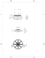
FIG. 1 is a front perspective view of a vented container system in accordance with an illustrative embodiment; - FIG. 2A is a bottom view of a splash guard in accordance with an illustrative embodiment;
- FIG. 2B is a side view of a splash guard in accordance with an illustrative embodiment;
- FIG. 2C is an exploded side view of a splash guard in accordance with an illustrative embodiment;
-
FIG. 3A is a bottom view of a splash guard in accordance with an illustrative embodiment; -
FIG. 3B is a side view of a splash guard in accordance with an illustrative embodiment; -
FIG. 3C is an exploded side view of a splash guard in accordance with an illustrative embodiment. -
FIG. 1 illustrates an exemplary assembly of afitment 104, vent 101,vent membrane 106 andsplash guard 105 for assembly with acontainer 103 having liquids often used in an industrial cleaning process. Thecontainer 103 includes an opening 103b and an interior volume 103a adapted to store a liquid 102. The container may be a rigid structure, but the present disclosure contemplates containers of varied structure and dimension. For example, thecontainer 103 may be a flexible pouch capable of storing a liquid. Other exemplary containers may include bins, tubs, tubes, buckets, and the like. In addition to liquid chemical products, the present disclosure also envisions other material compositions that may adversely affect a vent membrane of a fitment, including but not limited slurries, powders, and granules. - Referring to
FIG. 1 , afitment 104 is seated in an opening 103b of acontainer 103. Thefitment 104 may have an outer surface on the lower perimeter 104b adapted to create a friction fit with thesplash guard 105. The lower surface of thesplash guard 105 may have a perimeter 105d that outwardly has a circumference slightly greater than the opening 103b of thecontainer 103, to secure thesplash guard 105 within the opening 103b. In one embodiment of thefitment 104, a cap (not shown) may be threadably or otherwise secured to thecontainer 103 with thefitment 104 installed. Thefitment 104 andsplash guard 105 may be installed prior to transport of thecontainer 103, e.g., prior to liquid is added. In one embodiment the opening 103b and thefitment 104 are generally disposed on the top of thecontainer 103 but it should be appreciated that any number of fitments may be included generally anywhere on thecontainer 103. Other configurations appreciated by those skilled in the art are also contemplated as part of the present disclosure. - The
fitment 104 has a vent 101 configured to permit gasses to escape from the interior of thecontainer 103, such as when the product stored therein is an off-gassing product. The vents 101 may comprise one or more orifices disposed about a center opening of thefitment 104, or otherwise compatible with the design and structure of thefitment 104. The venting may alternatively be based on the material properties of thefitment 104. Thesplash guard 105 may be secured to thefitment 104 via threading, friction fit, interference fit, counterpoising locking features, or any other connective means commonly known in the art. - A
vent membrane 106 is associated with thefitment 104. Thevent membrane 106 may be comprised of expanded polytetrafluoroethylene (ePTFE) to allow gasses to pass through the vents 101, while not allowing the liquid to pass through. Other gas-permeable, liquid-impermeable membranes may be used, including but not limited to those comprising PTFE, polypropylene or polyethylene. Thevent membrane 106 may be toroidal and configured to be inserted into thefitment 104, or of any suitable shape and/or size. For example, thevent membrane 106 may be a film associated with the vents 101. Thevent membrane 106 may be multilayered, either coaxially or linearly, of unitary construction, or varying cross section or thickness, or of any material and/or physical properties. - During shipment of the
container 103 filled with liquid 102, thecontainer 103 may be agitated for any number of reasons. Due to the composition of thevent membrane 106 and the chemical products often used in many different industries such as in cleaning processes, contact between the two reduces the effectiveness of thevent membrane 106. To minimize or preferably prevent contact of the liquid 102 with thevent membrane 106, asplash guard 105 is installed in afitment 104 which is then installed in the container, or asplash guard 105 is installed in the opening 103b or the neck 103c of the container, and then thefitment 104 is installed on thesplash guard 105. Thesplash guard 105 is secured to the lower perimeter 104b of thefitment 104. Thesplash guard 105 may be positioned on thefitment 104 such that a gap exists between thesplash guard 105 and thefitment 104. Because of the shape of thesplash guard 105, air or other gases will be able to exit thecontainer 103 in configurations where thesplash guard 105 is in contact with thefitment 104. - The geometry of the
splash guard 105 may be manufactured as desired to accommodate product containers with differing dimensions and differing neck geometries. Further, thesplash guard 105 may be manufactured through injection molding, but the present disclosure contemplates other manufacturing methods such as thermoforming, three-dimensional printing, pressure-formed plastic, low pressure molding, coinjection, spin casting, and the like. Still further, the splash guard 40 may be composed of plastic such as polyethylene terephthalate (PETE), high density polyethylene (HDPE), polyvinyl chloride (PVC), low density polyethylene (LDPE), and/or polypropylene (PP). The material is suitably rigid and does not adversely react with the chemical product 102 contained within thecontainer 103. The shape of thesplash guard 105, together with the manufacturing and materials options, advantageously provides for an inexpensive device that is easy to manufacture. - Referring to FIGS. 2A, 2B and 2C and
FIGS. 3A, 3B and 3C , an embodiment of asplash guard 105 is illustrated. Thesplash guard 105 has an upper perimeter 105b generally contoured to the lower perimeter 104b of thefitment 104. In an embodiment, the perimeter 105b and 104b are circular. Thesplash guard 105 includes an upper surface 105a and a lower surface 105c. The upper surface 105a may be substantially planar, concave or convex, and the lower surface 105c may be sloped from the perimeter 105d to an apex, e.g., an upside down cone or pyramid. The upper surface 105a may be substantially planar, concave or convex, and the lower surface 105b may have a plurality of ridges 105e radiating from a ring at the center of the lower surface 105b outwards towards the perimeter 105d, which top of the ridges may slope towards the perimeter 105d. When installed, the upper surface 105a is proximate to thefitment 104. - The
splash guard 105 may include a plurality of ridges 105e extending downwardly from the lower surface 105b. The ridges 105e may be disposed radially from the center which may take the shape of a ring. The ridges 105e may be any suitable shape. For example, the ridges 105e may have a top surface and two opposing surfaces. - The disclosure describes the embodiments of the invention in the context of chemical products such as those for cleaning processes. However, the splash guard may be applied across varied industries. For example, the splash guard may be incorporated into water care technology, such as water bottles with a vent and vent membrane (e.g., means for water purification). Further, the splash guard may be incorporated into pest elimination products, particularly those requiring vented containers to store hazardous chemicals. Still further, the splash guard may be incorporated into vented containers often used in the textile and/or laundry industries. Still yet further, the splash guard may be incorporated into the health care industry, as medical devices and/or containers used therein often require aspiration of a fluid.
- Some examples of the present subject matter include the following:
- Example 1 of the present subject matter is a splash guard for protecting a vent membrane associated with a fitment from a liquid in a container having an interior volume, the splash guard comprising: an upper surface having a perimeter substantially contoured to a lower perimeter of the fitment, said perimeter adapted to permit gas to escape from the interior volume of the container comprising a liquid; and a lower surface having a perimeter and configured to prevent liquid from splashing on the vent membrane, wherein the center of the lower surface comprises a ring affixed to a plurality of ridges radially extending from the center to the perimeter, each of the plurality of ridges having a top surface and opposing side surfaces, or wherein the lower surface comprises an inverted cone or pyramid shape.
- Example 2 is the splash guard of Example 1 wherein the perimeter is greater than the perimeter.
- Example 3 is the splash guard of Example 1 wherein the lower surface is sloped downwards towards the lower perimeter of the splash guard.
- Example 4 is the splash guard of Example 1 wherein the top surface of each of the plurality of ridges are sloped downwards from the ring toward the perimeter.
- Example 5 is the splash guard of Example 1 wherein the splash guard comprises polyethylene.
- Example 6 is the splash guard of Example 1 which is associated with a lower perimeter of the fitment.
- Example 7 is the splash guard of 1, wherein the fitment is adapted to seat in an opening of the container.
- Example 8 is the he splash guard of Example 1 which is adapted to seat in a neck of the container.
- Example 9 is a a system for protecting a vent membrane from a liquid in a container having an interior volume, the system comprising: a container having an interior volume and an opening, and optionally a neck; a fitment adapted to seat in the opening of the container, the fitment having an upper perimeter and a lower perimeter; a vent and the vent membrane which are associated with the fitment; and a splash guard disposed within the container, the splash guard associated with the lower perimeter of the fitment and allowing venting of the interior volume of the container while blocking liquid from contacting the vent membrane; said splash guard comprising: an upper surface having a perimeter substantially contoured to the lower perimeter of the fitment, said perimeter adapted to permit gas to escape from the interior volume of the container comprising a liquid; a lower surface having a perimeter and configured to prevent liquid from splashing on the vent membrane, wherein the center of the lower surface comprises a ring affixed to a plurality of ridges radially extending from the center to the perimeter, each of the plurality of ridges having a top surface and opposing side surfaces, or wherein the lower surface comprises an inverted cone or pyramid shape.
- Example 10 is the system of Example 9 wherein the perimeter is greater than the perimeter.
- Example 11 is the system of Example 9 wherein the top surface of each of the plurality of ridges are sloped downwards from the ring toward the perimeter.
- Example 12 is the system of Example 9 wherein the splash guard comprises polyethylene.
- Example 13 is the system of Example 9 wherein the perimeter of the splash guard is greater than the lower perimeter of the fitment.
- Example 14 is the system of Example 9 wherein the perimeter of the splash guard creates a friction fit to the lower perimeter of the fitment.
- Example 15 is the system of Example 9 wherein the container comprises a neck.
- Example 16 is the system of Example 15 wherein the splash guard is disposed within the neck.
- Example 17 is the system of Example 9 which comprises a liquid in the interior volume.
- Example 18 is the system of Example 17 wherein the liquid comprises an acid.
- Example 19 is a method for protecting a vent membrane from a liquid, the method comprising: providing a fitment adapted to seat in an opening of a container, the and installing a splash guard on the outer circumference of the lower perimeter of the fitment, said splash guard comprising: an upper surface having a perimeter substantially contoured to the lower perimeter of the fitment, said perimeter adapted to permit gas to escape from the interior volume of the container comprising a liquid; lower surface having a perimeter and configured to prevent liquid from splashing on the vent membrane, wherein the center of the lower surface comprises a ring affixed to a plurality of ridges radially extending from the center to the perimeter, each of the plurality of ridges having a top surface and opposing side surfaces, or wherein the lower surface comprises an inverted cone or pyramid shape.
- The invention is not to be limited to the particular embodiments described herein. In particular, the invention contemplates numerous variations in the type of ways in which embodiments of the invention can be applied to protect a vent membrane in a fitment connected to a liquid product container during transport. The foregoing description has been presented for purposes of illustration and description. It is not intended to be an exhaustive list or limit any of the invention to the precise forms disclosed. It is contemplated that other alternatives or exemplary aspects that are considered included in the invention. The description is merely examples of embodiments, processes or methods of the invention. It is understood that any other modifications, substitutions, and/or additions can be made, which are within the intended scope of the invention.
-
- 1. A splash guard (105) for protecting a vent membrane (106) associated with a fitment (104) from a liquid (102) in a container (103) having an interior volume (103a), the splash guard comprising:
- an upper surface (105a) having a perimeter (105b) substantially contoured to a lower perimeter (104b) of the fitment, said perimeter (105b) adapted to permit gas to escape from the interior volume of the container comprising a liquid; and
- a lower surface (105c) having a perimeter (105d) and configured to prevent liquid from splashing on the vent membrane, wherein the center of the lower surface comprises a ring affixed to a plurality of ridges radially extending from the center to the perimeter (105d), each of the plurality of ridges having a top surface and opposing side surfaces, or wherein the lower surface comprises an inverted cone or pyramid shape.
- 2. The splash guard of 1 wherein the perimeter (105d) is greater than the perimeter (105b).
- 3. The splash guard of 1 wherein the lower surface (105c) is sloped downwards towards the lower perimeter (104b) of the splash guard.
- 4. The splash guard of 1 wherein the top surface of each of the plurality of ridges are sloped downwards from the ring toward the perimeter.
- 5. The splash guard of 1 wherein the splash guard comprises polyethylene.
- 6. The slash guard of 1 which is associated with a lower perimeter (104a) of the fitment (104).
- 7. The splash guard of 7 wherein the fitment is adapted to seat in the opening (103b) of the container.
- 8. The splash guard of 1 which is adapted to seat in a neck of the container.
- 9. A system (100) for protecting a vent membrane (106) from a liquid (102) in a container (103) having an interior volume (103a), the system comprising:
- a container (103) having an interior volume (103a) and an opening (103b), and optionally a neck (103c);
- a fitment (104) adapted to seat in the opening (103b) of the container, the fitment having an upper perimeter (104a) and a lower perimeter (104b);
- a vent (101) and the vent membrane (106) which are associated with the fitment; and
- a splash guard (105) disposed within the container (103), the splash guard associated with the lower perimeter of the fitment (104b) and allowing venting of the interior volume of
- the container while blocking liquid from contacting the vent membrane;
- said splash guard comprising:
- an upper surface (105a) having a perimeter (105b) substantially contoured to the lower perimeter (104b) of the fitment, said perimeter (105b) adapted to permit gas to escape from the interior volume of the container comprising a liquid;
- a lower surface (105c) having a perimeter (105d) and configured to prevent liquid from splashing on the vent membrane, wherein the center of the lower surface comprises a ring affixed to a plurality of ridges radially extending from the center to the perimeter (105d), each of the plurality of ridges having a top surface and opposing side surfaces, or wherein the lower surface comprises an inverted cone or pyramid shape.
- 10. The system of 9 wherein the perimeter (105d) is greater than the perimeter (105b).
- 11. The system of 9 wherein the top surface of each of the plurality of ridges are sloped downwards from the ring toward the perimeter.
- 12. The system of 9 wherein the splash guard comprises polyethylene.
- 13. The system of 9 wherein the perimeter (105b) of the splash guard is greater than the lower perimeter (104b) of the fitment.
- 14. The system of 9 wherein the perimeter (105b) of the splash guard creates a friction fit to the lower perimeter (104b) of the fitment.
- 15. The system of 9 wherein the container comprises a neck.
- 16. The system of 15 wherein the splash guard is disposed within the neck.
- 17. The system of 9 which comprises a liquid in the interior volume.
- 18. The system of 17 wherein the liquid comprises an acid.
- 19. A method for protecting a vent membrane (106) from a liquid, the method comprising:
- providing a fitment (104) adapted to seat in an opening (103b) of a container (103), the and
- installing a splash guard (105) on the outer circumference of the lower perimeter (104b) of the fitment, said splash guard comprising:
- an upper surface (105a) having a perimeter (105b) substantially contoured to the lower perimeter (104b) of the fitment, said perimeter (105b) adapted to permit gas to escape from the interior volume of the container comprising a liquid;
- lower surface (105c) having a perimeter (105d) and configured to prevent liquid from splashing on the vent membrane, wherein the center of the lower surface comprises a ring affixed to a plurality of ridges radially extending from the center to the perimeter (105d), each of the plurality of ridges having a top surface and opposing side surfaces, or wherein the lower surface comprises an inverted cone or pyramid shape.
Claims (9)
- A system (100) for protecting a vent membrane (106) from a liquid (102) in a container (103) having an interior volume (103a), the system comprising:a fitment (104), the fitment having an upper perimeter (104a) and a lower perimeter (104b);a vent (101) and the vent membrane (106) which are associated with the fitment; anda splash guard (105);said splash guard comprising:an upper surface (105a) having a perimeter (105b) substantially contoured to the lower perimeter (104b) of the fitment, said perimeter (105b) adapted to permit gas to escape from the interior volume of the container comprising a liquid;a lower surface (105c) having a perimeter (105d) and configured to prevent liquid from splashing on the vent membrane, wherein the center of the lower surface comprises a ring affixed to a plurality of ridges radially extending from the center to the perimeter (105d), each of the plurality of ridges having a top surface and opposing side surfaces, or wherein the lower surface comprises an inverted cone or pyramid shape.
- The system of claim 1 further comprising a container (103) having an interior volume (103a) and an opening (103b), and optionally a neck (103c).
- The system of claim 2 wherein the fitment (104) is adapted to seat in the opening (103b) of the container.
- The system of claim 2 or 3 wherein the splash guard (105) is disposed within the container (103), the splash guard associated with the lower perimeter of the fitment (104b) and allowing venting of the interior volume of the container while blocking liquid from contacting the vent membrane.
- The system of any of the preceding claims wherein the perimeter (105d) is greater than the perimeter (105b).
- The system of any of the preceding claims wherein the top surface of each of the plurality of ridges are sloped downwards from the ring toward the perimeter.
- The system of any of the preceding claims wherein the splash guard comprises polyethylene.
- The system of any of the preceding claims wherein the perimeter (105b) of the splash guard is greater than the lower perimeter (104b) of the fitment.
- The system of any of the preceding claims wherein the perimeter (105b) of the splash guard creates a friction fit to the lower perimeter (104b) of the fitment.
Applications Claiming Priority (3)
| Application Number | Priority Date | Filing Date | Title |
|---|---|---|---|
| US201862784203P | 2018-12-21 | 2018-12-21 | |
| EP19842516.7A EP3898446B1 (en) | 2018-12-21 | 2019-12-20 | Splash guard for vented containers |
| PCT/US2019/068101 WO2020132598A1 (en) | 2018-12-21 | 2019-12-20 | Splash guard for vented containers |
Related Parent Applications (1)
| Application Number | Title | Priority Date | Filing Date |
|---|---|---|---|
| EP19842516.7A Division EP3898446B1 (en) | 2018-12-21 | 2019-12-20 | Splash guard for vented containers |
Publications (2)
| Publication Number | Publication Date |
|---|---|
| EP4249392A2 true EP4249392A2 (en) | 2023-09-27 |
| EP4249392A3 EP4249392A3 (en) | 2024-01-10 |
Family
ID=69187973
Family Applications (2)
| Application Number | Title | Priority Date | Filing Date |
|---|---|---|---|
| EP19842516.7A Active EP3898446B1 (en) | 2018-12-21 | 2019-12-20 | Splash guard for vented containers |
| EP23181698.4A Withdrawn EP4249392A3 (en) | 2018-12-21 | 2019-12-20 | Splash guard for vented containers |
Family Applications Before (1)
| Application Number | Title | Priority Date | Filing Date |
|---|---|---|---|
| EP19842516.7A Active EP3898446B1 (en) | 2018-12-21 | 2019-12-20 | Splash guard for vented containers |
Country Status (3)
| Country | Link |
|---|---|
| US (1) | US12060205B2 (en) |
| EP (2) | EP3898446B1 (en) |
| WO (1) | WO2020132598A1 (en) |
Families Citing this family (3)
| Publication number | Priority date | Publication date | Assignee | Title |
|---|---|---|---|---|
| CA3110527A1 (en) * | 2018-08-31 | 2020-03-05 | FUJIFILM Irvine Scientific, Inc. | Venting system for a mixing apparatus |
| WO2020132598A1 (en) | 2018-12-21 | 2020-06-25 | Ecolab Usa Inc. | Splash guard for vented containers |
| CN115339760B (en) * | 2022-10-15 | 2023-01-06 | 北矿化学科技(沧州)有限公司 | Packaging cover with breather valve |
Citations (1)
| Publication number | Priority date | Publication date | Assignee | Title |
|---|---|---|---|---|
| US20130153592A1 (en) | 2011-12-16 | 2013-06-20 | Ecolab Usa Inc. | Vented insert for a liquid pouch fitment |
Family Cites Families (4)
| Publication number | Priority date | Publication date | Assignee | Title |
|---|---|---|---|---|
| ES2122352T3 (en) * | 1994-02-22 | 1998-12-16 | Sotralentz Sa | CONTAINER FOR FLOWING MEDIA WITH VENTILATION DEVICE. |
| US9919850B2 (en) * | 2013-02-12 | 2018-03-20 | Ecolab Usa Inc. | Vented fitment for flexible pouch |
| US9682393B2 (en) | 2015-03-17 | 2017-06-20 | Ecolab Usa Inc. | Fitment splash guard |
| WO2020132598A1 (en) | 2018-12-21 | 2020-06-25 | Ecolab Usa Inc. | Splash guard for vented containers |
-
2019
- 2019-12-20 WO PCT/US2019/068101 patent/WO2020132598A1/en not_active Ceased
- 2019-12-20 EP EP19842516.7A patent/EP3898446B1/en active Active
- 2019-12-20 US US16/723,900 patent/US12060205B2/en active Active
- 2019-12-20 EP EP23181698.4A patent/EP4249392A3/en not_active Withdrawn
Patent Citations (1)
| Publication number | Priority date | Publication date | Assignee | Title |
|---|---|---|---|---|
| US20130153592A1 (en) | 2011-12-16 | 2013-06-20 | Ecolab Usa Inc. | Vented insert for a liquid pouch fitment |
Also Published As
| Publication number | Publication date |
|---|---|
| EP4249392A3 (en) | 2024-01-10 |
| US20200198858A1 (en) | 2020-06-25 |
| EP3898446A1 (en) | 2021-10-27 |
| EP3898446B1 (en) | 2023-06-28 |
| US12060205B2 (en) | 2024-08-13 |
| WO2020132598A1 (en) | 2020-06-25 |
Similar Documents
| Publication | Publication Date | Title |
|---|---|---|
| EP3898446B1 (en) | Splash guard for vented containers | |
| US8733598B2 (en) | Closure/connector for liner-based dispense containers | |
| US11535433B2 (en) | Container closure with venting seal | |
| US6325253B1 (en) | Self-closing fluid dispensing closure | |
| US9580224B2 (en) | Composite container with internal fitment | |
| US9254929B2 (en) | Reusable food container with re-sealable cap | |
| US20150048113A1 (en) | Two-piece child-resistant dispensing closure | |
| JP6427410B2 (en) | Squeeze container with slit valve | |
| JP2000153886A (en) | Liquid distribution device and liquid holding container | |
| EP3271261B1 (en) | Fitment splash guard | |
| AU710641B2 (en) | Draining means for venting systems | |
| US11998144B2 (en) | Systems and methods for a mixing container | |
| US20190185242A1 (en) | Lid for containers under vacuum | |
| US20240278962A1 (en) | Poppet lid | |
| EP3282919B1 (en) | Packaging concept for solid products | |
| AU2016386856B2 (en) | Container with abrasion resistant rim | |
| JP4880239B2 (en) | Degassing lid for plastic containers | |
| CN101500903B (en) | Vent cap and container with such vent cap | |
| JP6269978B2 (en) | Plastic cap |
Legal Events
| Date | Code | Title | Description |
|---|---|---|---|
| PUAI | Public reference made under article 153(3) epc to a published international application that has entered the european phase |
Free format text: ORIGINAL CODE: 0009012 |
|
| STAA | Information on the status of an ep patent application or granted ep patent |
Free format text: STATUS: THE APPLICATION HAS BEEN PUBLISHED |
|
| AC | Divisional application: reference to earlier application |
Ref document number: 3898446 Country of ref document: EP Kind code of ref document: P |
|
| AK | Designated contracting states |
Kind code of ref document: A2 Designated state(s): AL AT BE BG CH CY CZ DE DK EE ES FI FR GB GR HR HU IE IS IT LI LT LU LV MC MK MT NL NO PL PT RO RS SE SI SK SM TR |
|
| REG | Reference to a national code |
Ref country code: DE Ref legal event code: R079 Free format text: PREVIOUS MAIN CLASS: B65D0077220000 Ipc: B65D0051160000 |
|
| PUAL | Search report despatched |
Free format text: ORIGINAL CODE: 0009013 |
|
| AK | Designated contracting states |
Kind code of ref document: A3 Designated state(s): AL AT BE BG CH CY CZ DE DK EE ES FI FR GB GR HR HU IE IS IT LI LT LU LV MC MK MT NL NO PL PT RO RS SE SI SK SM TR |
|
| RIC1 | Information provided on ipc code assigned before grant |
Ipc: B65D 77/22 20060101ALI20231204BHEP Ipc: B65D 51/16 20060101AFI20231204BHEP |
|
| STAA | Information on the status of an ep patent application or granted ep patent |
Free format text: STATUS: REQUEST FOR EXAMINATION WAS MADE |
|
| STAA | Information on the status of an ep patent application or granted ep patent |
Free format text: STATUS: THE APPLICATION HAS BEEN WITHDRAWN |
|
| 17P | Request for examination filed |
Effective date: 20240708 |
|
| RBV | Designated contracting states (corrected) |
Designated state(s): AL AT BE BG CH CY CZ DE DK EE ES FI FR GB GR HR HU IE IS IT LI LT LU LV MC MK MT NL NO PL PT RO RS SE SI SK SM TR |
|
| 18W | Application withdrawn |
Effective date: 20240725 |