EP4249377A1 - Passenger seat armrest recline mechanism - Google Patents
Passenger seat armrest recline mechanism Download PDFInfo
- Publication number
- EP4249377A1 EP4249377A1 EP23163748.9A EP23163748A EP4249377A1 EP 4249377 A1 EP4249377 A1 EP 4249377A1 EP 23163748 A EP23163748 A EP 23163748A EP 4249377 A1 EP4249377 A1 EP 4249377A1
- Authority
- EP
- European Patent Office
- Prior art keywords
- seat
- seat pan
- armrest
- linkage
- passenger seat
- Prior art date
- Legal status (The legal status is an assumption and is not a legal conclusion. Google has not performed a legal analysis and makes no representation as to the accuracy of the status listed.)
- Granted
Links
Images




Classifications
-
- B—PERFORMING OPERATIONS; TRANSPORTING
- B64—AIRCRAFT; AVIATION; COSMONAUTICS
- B64D—EQUIPMENT FOR FITTING IN OR TO AIRCRAFT; FLIGHT SUITS; PARACHUTES; ARRANGEMENT OR MOUNTING OF POWER PLANTS OR PROPULSION TRANSMISSIONS IN AIRCRAFT
- B64D11/00—Passenger or crew accommodation; Flight-deck installations not otherwise provided for
- B64D11/06—Arrangements of seats, or adaptations or details specially adapted for aircraft seats
- B64D11/0648—Lower frame constructions
-
- B—PERFORMING OPERATIONS; TRANSPORTING
- B64—AIRCRAFT; AVIATION; COSMONAUTICS
- B64D—EQUIPMENT FOR FITTING IN OR TO AIRCRAFT; FLIGHT SUITS; PARACHUTES; ARRANGEMENT OR MOUNTING OF POWER PLANTS OR PROPULSION TRANSMISSIONS IN AIRCRAFT
- B64D11/00—Passenger or crew accommodation; Flight-deck installations not otherwise provided for
- B64D11/06—Arrangements of seats, or adaptations or details specially adapted for aircraft seats
- B64D11/0639—Arrangements of seats, or adaptations or details specially adapted for aircraft seats with features for adjustment or converting of seats
- B64D11/0641—Seats convertible into beds
-
- B—PERFORMING OPERATIONS; TRANSPORTING
- B64—AIRCRAFT; AVIATION; COSMONAUTICS
- B64D—EQUIPMENT FOR FITTING IN OR TO AIRCRAFT; FLIGHT SUITS; PARACHUTES; ARRANGEMENT OR MOUNTING OF POWER PLANTS OR PROPULSION TRANSMISSIONS IN AIRCRAFT
- B64D11/00—Passenger or crew accommodation; Flight-deck installations not otherwise provided for
- B64D11/06—Arrangements of seats, or adaptations or details specially adapted for aircraft seats
- B64D11/0639—Arrangements of seats, or adaptations or details specially adapted for aircraft seats with features for adjustment or converting of seats
- B64D11/064—Adjustable inclination or position of seats
-
- B—PERFORMING OPERATIONS; TRANSPORTING
- B64—AIRCRAFT; AVIATION; COSMONAUTICS
- B64D—EQUIPMENT FOR FITTING IN OR TO AIRCRAFT; FLIGHT SUITS; PARACHUTES; ARRANGEMENT OR MOUNTING OF POWER PLANTS OR PROPULSION TRANSMISSIONS IN AIRCRAFT
- B64D11/00—Passenger or crew accommodation; Flight-deck installations not otherwise provided for
- B64D11/06—Arrangements of seats, or adaptations or details specially adapted for aircraft seats
- B64D11/0639—Arrangements of seats, or adaptations or details specially adapted for aircraft seats with features for adjustment or converting of seats
- B64D11/0644—Adjustable arm rests
Definitions
- the present invention generally relates to aircraft seating, and more specifically to reclining mechanisms for aircraft seating.
- Business class airline passenger seats are typically adjustable between upright and lie-flat positions to provide passenger comfort and comply with taxi, take-off and landing seating position requirements.
- Such passenger seats typically include a seatback and seat pan, often linked in motion, supported by a frame and angularly adjustable by way of a seat recline mechanism.
- Conventional passenger seats typically include an adjustable or fixed armrest.
- the trend in commercial business class is seats that articulate to form a full flat bed. In the vast majority of the business class seats, as the seat translates forward from upright to a bed mode the armrest does not follow this motion and remains in the same location. This creates a problem because as the seat is moving forward the usable portion of the armrest gets smaller and smaller. Ideally, you want to have armrests that are part of the seat and move with the seat pan. Therefore, it would be advantageous to provide a device, system, and method that cures the shortcomings described above.
- the passenger seat includes a seat pan including a housing and bracket fixed to the housing.
- the passenger seat includes a seatback.
- the seat pan and the seatback including a first pivot joint by which the seatback is pivotally connected to the seat pan.
- the passenger seat includes an armrest.
- the armrest includes a brace fixed to the armrest.
- the brace and the seatback including a second pivot joint by which the armrest is pivotally connected to the seatback.
- the passenger seat includes a linkage connected between the seat pan and the armrest.
- the bracket and the linkage including a third pivot joint by which the linkage is pivotally connected to the seat pan.
- the brace and the linkage including a fourth joint by which the linkage is pivotally connected to the armrest.
- the passenger seat is configurable between an upright position and a bed position.
- the linkage is disposed within the housing.
- an angle of the seat pan is adjusted as the passenger seat is configured between the upright position and the bed position.
- the armrest follows the seat pan by the linkage.
- the aircraft includes a floor.
- the aircraft includes a plurality of passenger seats.
- each of the plurality of passenger seats includes a spreader mounted to the floor.
- each of the plurality of passenger seats includes a seat pan including a bracket fixed to the seat pan.
- each of the plurality of passenger seats includes a seatback.
- the seat pan and the seatback including a first pivot joint by which the seatback is pivotally connected to the seat pan.
- each of the plurality of passenger seats includes an armrest.
- the armrest including a housing and a brace fixed to the housing.
- the brace and the seatback including a second pivot joint by which the armrest is pivotally connected to the seatback.
- each of the plurality of passenger seats includes a linkage connected between the seat pan and the armrest.
- the bracket and the linkage including a third pivot joint by which the linkage is pivotally connected to the seat pan.
- the brace and the linkage including a fourth joint by which the linkage is pivotally connected to the armrest.
- the linkage is disposed within the housing.
- the passenger seat is configurable between an upright position and a bed position.
- an angle of the seat pan is adjusted as the passenger seat is configured between the upright position and the bed position.
- the armrest follows the seat pan by the linkage.
- a letter following a reference numeral is intended to reference an embodiment of the feature or element that may be similar, but not necessarily identical, to a previously described element or feature bearing the same reference numeral (e.g., 1, 1a, 1b).
- reference numeral e.g. 1, 1a, 1b
- Such shorthand notations are used for purposes of convenience only and should not be construed to limit the disclosure in any way unless expressly stated to the contrary.
- any reference to “one embodiment” or “some embodiments” means that a particular element, feature, structure, or characteristic described in connection with the embodiment is included in at least one embodiment disclosed herein.
- the appearances of the phrase “in some embodiments” in various places in the specification are not necessarily all referring to the same embodiment, and embodiments may include one or more of the features expressly described or inherently present herein, or any combination or sub-combination of two or more such features, along with any other features which may not necessarily be expressly described or inherently present in the instant disclosure.
- Embodiments of the present disclosure are generally directed to a passenger seat including an armrest recline mechanism that causes the armrests to follow the seat pan.
- the armrest recline mechanism includes a linkage connecting the armrest with the seat pan, thereby causing the armrest to follow the motion of the seat pan.
- the linkage is constructed such that the armrest is aligned with the seat pan when the passenger seat is in a bed position (also referred to as a lie-flat position). By keeping the armrest aligned with the seat pan, such component may be parallel or substantially parallel (e.g., as parallel as possible) through positions in the translation.
- the linkage also provides smooth kinematic motion for the armrest as the seat transitions between the bed position and an upright position (also referred to as a taxi, takeoff, and landing (TTOL) position).
- the armrest may also maintain an aligned relationship (e.g., substantially parallel) to the seat pan over a portion of the followed motion.
- the passenger seats 102 may be coupled to a floor 109 of an aircraft 100.
- the passenger seat 102 includes a seatback 104 and a seat pan 106.
- the seatback 104 may include an upper portion and a lower portion.
- the passenger seat 102 also includes a spreader 108 (also referred to as a seat support structure, a seat chassis, and the like) that is configured to mount to a floor 109 of the aircraft 100 for providing structural support to various components of the passenger seat 102, such as the seat pan 106 and the seatback 104.
- the spreader 108 may be coupled to the floor 109 by a track (e.g., an anti-rattle track), or the like. Multiple of the spreaders 108 (e.g., a left spreader and a right spreader) may be connected by a transverse tube (not depicted).
- the seatback 104 and the seat pan 106 may be separate structures and/or may include one or more shared components.
- the seatback 104 and the seat pan 106 can have a shared cushion or covering.
- one or more of the seatback 104 and the seat pan 106 may be configured to move.
- the seatback 104 and the seat pan 106 can be actuated such that the passenger seat 102 may be configurable between an upright position and a bed position.
- the passenger seat 102 may also include one or more armrests 110 (e.g., a left armrest and a right armrest).
- the armrest 110 may be pivotally connected to the seatback 104.
- the armrest 110 may include a housing 130 which protects a passenger from interacting with components disposed therein.
- the housing 130 of the armrest 110 may include a padded top surface on which the passenger may rest their arms.
- the housing 130 of the armrest 110 may also include a flat face on the interior sides of the passenger seat 102, and may be covered by a number of materials.
- the passenger seat 102 may include a brace 112, a linkage 120, a bracket 122, and one or more pivot joints (e.g., a pivot joint 114, a pivot joint 118, a pivot joint 124, a pivot joint 126).
- the term pivot joint may also be referred to herein as a pin joint, a revolute joint, or the like.
- Such pivot joints may generally be understood to include one degree of freedom allowing rotation about an axis.
- the pivot joints may permit relative rotational motion of the linkage 120 relative to the brace 112, the linkage 120 relative to the bracket 122, and the seat pan 106 relative to the seatback 104.
- the brace 112 may be provided in a rigid arrangement with the armrest 110 and the bracket 122 may be provided in a rigid arrangement with the seat pan 106.
- the seat pan 106 and the seatback 104 including a pivot joint 126 by which the seatback 104 is pivotally connected to the seat pan 106.
- the linkage 120 pivots about the pivot joint 118 with respect to the brace 112 and pivots about the pivot joint 124 with respect to the bracket 122, thereby causing movement of the armrest 110.
- the armrest 110 then pivots with respect to the seatback 104 about the pivot joint 114.
- the relative movements of the rigid bodies about the pivot joint 114, the pivot joint 118, the pivot joint 124, and the pivot joint 126 may be kinematically represented as a four-bar linkage, which may be further coupled to a camming mechanism on the spreader 108 and a recline mechanism between the seat pan 106 and the seatback 104.
- the arrangement of the brace 112, the linkage 120, and the bracket 122 may provide for sufficient rotational motion in combination with the camming mechanism on the spreader 108 and the recline mechanism between the seat pan 106 and the seatback 104, to achieve the upright position and the bed position.
- the armrest 110 includes the brace 112 fixed to the armrest 110.
- the brace 112 may be fixed to the housing 130 of the armrest 110 by a fastener, adhesive, and the like. The brace 112 may then reinforce the armrest 110.
- the brace 112 may be fixed within the armrest 110 such that rotational motion of the brace 112 is imparted to the armrest 110.
- the brace 112 may also include one or more features for coupling the armrest 110 to other components of the passenger seat 102.
- the brace includes a pivot joint 114.
- the pivot joint 114 may be provided between the brace 112 and the seatback 104. In this regard, the brace 112 may pivot about the pivot joint 114 relative to the seatback 104.
- the brace 112 may also include a truss member 116 extending downwards from the pivot joint 114.
- the truss member 116 may be joined with the brace 112.
- the truss member 116 may be joined with the brace 112 during fabrication of the truss member 116, such as by injection molding, thermo forming, compression molding, or the like.
- the truss member 116 may be formed as a constituent member of the brace 112.
- the truss member 116 may also be joined with the brace 112 by a fastener or the like.
- the truss member 116 includes a triangular shape.
- the triangular shape of the truss member 116 may include a vertex.
- the truss member 116 may also include a pivot joint 118 disposed proximal to the vertex (e.g., at or offset to the side).
- the pivot joint 118 may be provided between the brace 112 and the linkage 120.
- the brace 112 may pivot about the pivot joint 114 relative to the linkage 120.
- the brace 112 may include a number of shapes suitable for the pivot joint 114 and the pivot joint 118.
- the use of the truss member 116 may be advantageous in both providing sufficient strength for pivot joint 118 while also reducing a weight associated with brace 112.
- the passenger seat 102 includes the linkage 120.
- the linkage 120 may be connected between the seat pan 106 and the armrest 110.
- the linkage 120 may be pivotably connected to the brace 112 at the pivot joint 118, such that the linkage 120 is pivotally connected to the armrest 110.
- the linkage 120 may also be pivotably connected to the bracket 122 at the pivot joint 124, such that the linkage 120 is pivotally connected to the seat pan 106.
- the linkage 120 may transmit motion between the seat pan 106 and the armrest 110 for causing the armrest 110 to rotate and be vertically displaced.
- the linkage 120 may generally include a rigid member for transmitting the motion with minimal bending.
- the passenger seat 102 includes the bracket 122.
- the bracket 122 may include a first end and a second end connected to form a u-shape, such that the bracket 122 may be considered a u-shaped bracket.
- the first end of the bracket 122 may be fixed to the seat pan 106.
- the bracket 122 and the seat pan 106 may be considered a rigid body.
- the second end of the bracket 122 may include the pivot joint 124.
- the linkage 120 may be pivotably coupled to the seat pan 106 by way of the pivot joint 124 and the bracket 122.
- the use of the u-shape for the bracket 122 may be advantageous for providing the bracket 122 with the ability to receive one or more components of the passenger seat 102, such as, but not limited to, the housing 130 of the armrest 110.
- the bracket 122 may be provided within a hole of the housing 130, reducing a likelihood a passenger accessing the linkage 120 (e.g., a pinch point).
- the spreader 108 may include a guide path 128 which acts as a linear cam.
- linear cam is meant to refer to a cam element which moves in a linear fashion along a slotted hole, a cammed surface, a guide path, or the like.
- the seat pan 106 may include a component, such as a roller, which interfaces with the guide path 128 to follow the guide path 128. Such roller may be in a fixed relation with the pivot joint 126.
- the motive force which configures the passenger seat 102 between the upright position and the bed position may be provided by the guide path 128.
- the guide path 128 may include a first end point and a second end point.
- the first end point of the guide path 128 may correspond to the upright position of the passenger seat 102, such that passenger seat 102 may be in the upright position when the follower of the seat pan 106 is disposed at the first end point, as depicted in FIG. 2A .
- the second end point may correspond to the bed position of the passenger seat 102, such that passenger seat 102 may be in the bed position when the follower of the seat pan 106 is disposed at the second end point, as depicted in FIG. 2G .
- the seat pan 106 is configured to follow the guide path 128 between the first end point and the second end point as the passenger seat 102 is configured between the upright position and the bed position.
- the seat pan 106 may also configured to follow the guide path 128 between the second end point and the first end point as the passenger seat 102 is configured between the bed position and the seat position.
- the guide path may include one or more angles.
- the guide path may include a first angle, a second angle, and a third angle such that the guide path 128 includes a substantially arcuate shape.
- the first end point of the guide path may be disposed at the first angle and the second end point of the guide path may be disposed at the third angle, with the second angle joining the first angle and the second angle.
- the ends of the guide path 128 may be at a highest vertical point (i.e., the guide path opens upward) with the forward end being slightly higher than the rear ward end. In this arrangement, the rear end of the seat pan 106 is lowest at mid recline to provide a cradling sitting position.
- a passenger seat is described in U.S. Patent No. 9,174,737 , titled "AIRCRAFT SEAT WITH TRANSLATING SEATBACK LINKAGE PIVOT", which is incorporated herein.
- the arrangement, position, and lengths of the brace 112, the linkage 120, and the bracket 122 is selected to control the surfaces of one or more of the armrest 110, the seatback 104, or the seat pan 106 in one or more of the upright position, the bed position, and/or while translating between the upright position and the bed position.
- FIGS. 2A depicts, the top surface of the armrest being aligned with the floor when the passenger seat is configured in the upright position.
- FIGS. 2A-C depicts the top surface of the armrest including an offset angle from the top surface of the seat pan as the seat pan follows along the first angle and the second angle of the guide path.
- FIGS. 2D-2D further depicts the top surface of the armrest aligned with the top surface of the seat pan as the seat pan.
- FIGS. 2D-2G depicts the top surface of the armrest 110 aligned with the top surface of the seat pan 106 as the seat pan 106 follows along the third angle of the guide path 128. Such alignment may be due to the linkage 120 keeping parallelism between the seat pan 106 and armrest 110.
- FIGS. 2D-2F depicts the top surface of the armrest 110 and the top surface of the seat pan 106 at an offset angle from the floor 109 for a portion of the guide path 128 as the seat pan follows along the third angle of the guide path 128.
- FIG. 2G further depicts the top surface of the armrest 110 and the top surface of the seat pan 106 aligned when the passenger seat is configured in the bed position. This arrangement may be beneficial in providing a flat surface on which a passenger may sleep.
- the arrangement described above thus provides for a smooth transition from the upright position, where the top surface of the seat pan 106 is offset from the armrest 110, to the bed position, where the top surface of the seat pan 106 is aligned with the top surface of the armrest 110.
- the armrest 110 is automatically raised and lowered by the linkage 120 as the passenger seat 102 is transitioned between the upright position and the bed position.
- the passenger does not need to manually raise or lower the armrest 110.
- the armrest 110 may be raised and lowered without requiring an electrical actuator, a hydraulic actuator, or the like.
- the linkage 120 may also be relatively light weight and include minimal translating components.
- the brace 112 the linkage 120, the bracket 122, and a camming surface of the spreader 108 are highlighted for clarity and emphasis, while some portions of the passenger seat 102, e.g., the seatback 104, the seat pan 106, or the armrest 110 are deemphasized. Other portions of the passenger seat 102, e.g., the recline mechanism for the seatback 104, are not shown to avoid confusion and unnecessary detail.
- the recline mechanism for the seatback 104 a linkage coupled between the seat pan 106 and the seatback 104, which motivates the seatback 104 into the bed position as the angle of the seat pan 106 is adjusted.
- Such linkage may include a pivot point in common with the seat pan 106, pivotably coupling the linkage to the seat pan 106.
- the linkage may also include a guide path which the seatback is configured to follow.
- a recline mechanism for a seatback is described in U.S. Patent No. 10,450,072 , titled "SEATBACK ARTICULATION ASSEMBLY AND METHOD.
- the aircraft 100 including a perspective view of the passenger seat 102 in the bed position is described, in accordance with one or more embodiments of the present disclosure.
- the top surface (e.g., the arm pad) of the housing 130 of the armrest 110 may be made to be in substantially the same plane as the top surface (e.g., the seat cushion) of the seat pan 106.
- the top surface of the housing 130 of the armrest 110 may also be made to be in substantially the same plane as the seatback 104.
- the bracket 122 is formed as a u-shape with a first end of the bracket 122 fixed to the seat pan at a location 132 and with a second end including the pivot joint 124.
- the arrangement of the bracket 122 is advantageous in pivotally coupling the linkage 120 to the seat pan 106, while avoiding interference with the housing 130.
- the housing 130 may maintain a flush interior surface, thereby preventing pinching.
- the linkage 120 may be maintained within the housing 130 as the passenger seat 102 transitions between the upright position and the bed position.
- the linkage 120 may be provided within the armrest 110 and cause the armrest to move with the seat pan 106, achieving a desired kinematic motion.
- one or more of the aircraft 100 and the passenger seat 102 may include a passenger control panel.
- the passenger control panel may include a switch (or the like) which may re-position or configure the passenger seat 102 into the bed position.
- the passenger control panel may include a switch (or the like) which may re-position or configure the passenger seat 102 into the upright position.
- the passenger seat 102 may be actuated by engaging a handle that activates one or more mechanical assemblies for configuring the aircraft in the upright position and the bed position. Therefore, the above description should not be interpreted as a limitation on the scope of the disclosure but merely an illustration.
- the term "upright” seating position is used to describe a taxi, take-off and landing compliant seatback configuration
- the term “reclined” seating position is used to describe a seating position in which the seatback is reclined relative to the upright seatback configuration
- the term "lie-flat” position is used to describe a configuration in which the seatback and seat bottom form a substantially flat and continuous surface.
- the passenger seat 102 may be configured in accordance with aviation guidelines and/or standards put forth by, but not limited to: the Federal Aviation Administration (FAA), the European Aviation Safety Agency (EASA), or any other flight certification agency or organization; the American National Standards Institute (ANSI) or any other standards setting organization or company; and the like.
- FAA Federal Aviation Administration
- EASA European Aviation Safety Agency
- ANSI American National Standards Institute
- the passenger seat 102 may be installed within any number of environments.
- the environment may include any type of vehicle known in the art.
- the vehicle may be any air, land, or water-based personal equipment or vehicle; any air, land, or water-based commercial equipment or vehicle; any air, land, or water-based military equipment or vehicle known in the art.
- the environment may include a commercial or industrial establishment (e.g., a home or a business).
- the passenger seat includes the various components described herein on each side of the seat which work in cooperation to adjust the seating position and the armrest position.
Landscapes
- Engineering & Computer Science (AREA)
- Aviation & Aerospace Engineering (AREA)
- Seats For Vehicles (AREA)
Abstract
Description
- The present invention generally relates to aircraft seating, and more specifically to reclining mechanisms for aircraft seating.
- Business class airline passenger seats are typically adjustable between upright and lie-flat positions to provide passenger comfort and comply with taxi, take-off and landing seating position requirements. Such passenger seats typically include a seatback and seat pan, often linked in motion, supported by a frame and angularly adjustable by way of a seat recline mechanism. Conventional passenger seats typically include an adjustable or fixed armrest. The trend in commercial business class is seats that articulate to form a full flat bed. In the vast majority of the business class seats, as the seat translates forward from upright to a bed mode the armrest does not follow this motion and remains in the same location. This creates a problem because as the seat is moving forward the usable portion of the armrest gets smaller and smaller. Ideally, you want to have armrests that are part of the seat and move with the seat pan. Therefore, it would be advantageous to provide a device, system, and method that cures the shortcomings described above.
- A passenger seat is disclosed, in accordance with one or more embodiments of the present disclosure. In one illustrative embodiment, the passenger seat includes a seat pan including a housing and bracket fixed to the housing. In another illustrative embodiment, the passenger seat includes a seatback. In another illustrative embodiment, the seat pan and the seatback including a first pivot joint by which the seatback is pivotally connected to the seat pan. In another illustrative embodiment, the passenger seat includes an armrest. In another illustrative embodiment, the armrest includes a brace fixed to the armrest. In another illustrative embodiment, the brace and the seatback including a second pivot joint by which the armrest is pivotally connected to the seatback. In another illustrative embodiment, the passenger seat includes a linkage connected between the seat pan and the armrest. In another illustrative embodiment, the bracket and the linkage including a third pivot joint by which the linkage is pivotally connected to the seat pan. In another illustrative embodiment, the brace and the linkage including a fourth joint by which the linkage is pivotally connected to the armrest. In another illustrative embodiment, the passenger seat is configurable between an upright position and a bed position. In another illustrative embodiment, the linkage is disposed within the housing. In another illustrative embodiment, an angle of the seat pan is adjusted as the passenger seat is configured between the upright position and the bed position. In another illustrative embodiment, the armrest follows the seat pan by the linkage.
- An aircraft is disclosed, in accordance with one or more embodiments of the present disclosure. In one illustrative embodiment, the aircraft includes a floor. In another illustrative embodiment, the aircraft includes a plurality of passenger seats. In another illustrative embodiment, each of the plurality of passenger seats includes a spreader mounted to the floor. In another illustrative embodiment, each of the plurality of passenger seats includes a seat pan including a bracket fixed to the seat pan. In another illustrative embodiment, each of the plurality of passenger seats includes a seatback. In another illustrative embodiment, the seat pan and the seatback including a first pivot joint by which the seatback is pivotally connected to the seat pan. In another illustrative embodiment, each of the plurality of passenger seats includes an armrest. In another illustrative embodiment, the armrest including a housing and a brace fixed to the housing. In another illustrative embodiment, the brace and the seatback including a second pivot joint by which the armrest is pivotally connected to the seatback. In another illustrative embodiment, each of the plurality of passenger seats includes a linkage connected between the seat pan and the armrest. In another illustrative embodiment, the bracket and the linkage including a third pivot joint by which the linkage is pivotally connected to the seat pan. In another illustrative embodiment, the brace and the linkage including a fourth joint by which the linkage is pivotally connected to the armrest. In another illustrative embodiment, the linkage is disposed within the housing. In another illustrative embodiment, the passenger seat is configurable between an upright position and a bed position. In another illustrative embodiment, an angle of the seat pan is adjusted as the passenger seat is configured between the upright position and the bed position. In another illustrative embodiment, the armrest follows the seat pan by the linkage.
- Implementations of the concepts disclosed herein may be better understood when consideration is given to the following detailed description thereof. Such description makes reference to the included drawings, which are not necessarily to scale, and in which some features may be exaggerated and some features may be omitted or may be represented schematically in the interest of clarity. Like reference numerals in the drawings may represent and refer to the same or similar element, feature, or function. In the drawings:
-
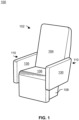
FIG. 1 depicts a perspective view of a passenger seat in an upright position, in accordance with one or more embodiments of the present disclosure. -
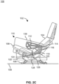
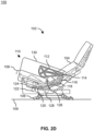
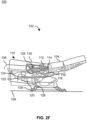
FIGS. 2A-2G depicts a side view of a passenger seat transitioning between an upright position and a bed position, in accordance with one or more embodiments of the present disclosure. -
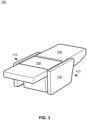
FIG. 3 depicts a perspective view of a passenger seat in a bed position, in accordance with one or more embodiments of the present disclosure. -
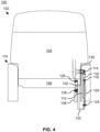
FIG. 4 depicts a partial front view of a passenger seat, in accordance with one or more embodiments of the present disclosure. - Before explaining one or more embodiments of the disclosure in detail, it is to be understood that the embodiments are not limited in their application to the details of construction and the arrangement of the components or steps or methodologies set forth in the following description or illustrated in the drawings. In the following detailed description of embodiments, numerous specific details may be set forth in order to provide a more thorough understanding of the disclosure. However, it will be apparent to one of ordinary skill in the art having the benefit of the instant disclosure that the embodiments disclosed herein may be practiced without some of these specific details. In other instances, well-known features may not be described in detail to avoid unnecessarily complicating the instant disclosure.
- As used herein a letter following a reference numeral is intended to reference an embodiment of the feature or element that may be similar, but not necessarily identical, to a previously described element or feature bearing the same reference numeral (e.g., 1, 1a, 1b). Such shorthand notations are used for purposes of convenience only and should not be construed to limit the disclosure in any way unless expressly stated to the contrary.
- Further, unless expressly stated to the contrary, "or" refers to an inclusive or and not to an exclusive or. For example, a condition A or B is satisfied by any one of the following: A is true (or present) and B is false (or not present), A is false (or not present) and B is true (or present), and both A and B are true (or present).
- In addition, use of "a" or "an" may be employed to describe elements and components of embodiments disclosed herein. This is done merely for convenience and "a" and "an" are intended to include "one" or "at least one," and the singular also includes the plural unless it is obvious that it is meant otherwise.
- Finally, as used herein any reference to "one embodiment" or "some embodiments" means that a particular element, feature, structure, or characteristic described in connection with the embodiment is included in at least one embodiment disclosed herein. The appearances of the phrase "in some embodiments" in various places in the specification are not necessarily all referring to the same embodiment, and embodiments may include one or more of the features expressly described or inherently present herein, or any combination or sub-combination of two or more such features, along with any other features which may not necessarily be expressly described or inherently present in the instant disclosure.
- Reference will now be made in detail to the subject matter disclosed, which is illustrated in the accompanying drawings. Embodiments of the present disclosure are generally directed to a passenger seat including an armrest recline mechanism that causes the armrests to follow the seat pan. The armrest recline mechanism includes a linkage connecting the armrest with the seat pan, thereby causing the armrest to follow the motion of the seat pan. The linkage is constructed such that the armrest is aligned with the seat pan when the passenger seat is in a bed position (also referred to as a lie-flat position). By keeping the armrest aligned with the seat pan, such component may be parallel or substantially parallel (e.g., as parallel as possible) through positions in the translation. The linkage also provides smooth kinematic motion for the armrest as the seat transitions between the bed position and an upright position (also referred to as a taxi, takeoff, and landing (TTOL) position). The armrest may also maintain an aligned relationship (e.g., substantially parallel) to the seat pan over a portion of the followed motion.
- An aircraft passenger seat is described in
U.S. Patent No. US 8,534,759 , titled "PASSENGER SEAT ARMREST RECLINE MECHANISM", which is incorporated herein by reference in the entirety. - Referring now to
FIG. 1 , a perspective view of apassenger seat 102 in an upright position is described, in accordance with one or more embodiments of the present disclosure. One or more of the passenger seats 102 may be coupled to afloor 109 of anaircraft 100. Thepassenger seat 102 includes aseatback 104 and aseat pan 106. Theseatback 104 may include an upper portion and a lower portion. Thepassenger seat 102 also includes a spreader 108 (also referred to as a seat support structure, a seat chassis, and the like) that is configured to mount to afloor 109 of theaircraft 100 for providing structural support to various components of thepassenger seat 102, such as theseat pan 106 and theseatback 104. Thespreader 108 may be coupled to thefloor 109 by a track (e.g., an anti-rattle track), or the like. Multiple of the spreaders 108 (e.g., a left spreader and a right spreader) may be connected by a transverse tube (not depicted). In embodiments, theseatback 104 and theseat pan 106 may be separate structures and/or may include one or more shared components. For example, theseatback 104 and theseat pan 106 can have a shared cushion or covering. In embodiments, one or more of theseatback 104 and theseat pan 106 may be configured to move. Theseatback 104 and theseat pan 106 can be actuated such that thepassenger seat 102 may be configurable between an upright position and a bed position. Thepassenger seat 102 may also include one or more armrests 110 (e.g., a left armrest and a right armrest). Thearmrest 110 may be pivotally connected to theseatback 104. Thearmrest 110 may include ahousing 130 which protects a passenger from interacting with components disposed therein. Thehousing 130 of thearmrest 110 may include a padded top surface on which the passenger may rest their arms. Thehousing 130 of thearmrest 110 may also include a flat face on the interior sides of thepassenger seat 102, and may be covered by a number of materials. - Referring now to
FIGS. 2A-2G , a partial side view showing internal components of thepassenger seat 102 as thepassenger seat 102 transitions between an upright position and a bed position is described, in accordance with one or more embodiments of the present disclosure. Thepassenger seat 102 may include abrace 112, alinkage 120, abracket 122, and one or more pivot joints (e.g., a pivot joint 114, a pivot joint 118, a pivot joint 124, a pivot joint 126). The term pivot joint may also be referred to herein as a pin joint, a revolute joint, or the like. Such pivot joints may generally be understood to include one degree of freedom allowing rotation about an axis. The pivot joints may permit relative rotational motion of thelinkage 120 relative to thebrace 112, thelinkage 120 relative to thebracket 122, and theseat pan 106 relative to theseatback 104. Thebrace 112 may be provided in a rigid arrangement with thearmrest 110 and thebracket 122 may be provided in a rigid arrangement with theseat pan 106. Theseat pan 106 and theseatback 104 including a pivot joint 126 by which theseatback 104 is pivotally connected to theseat pan 106. Thus, as theseatback 104 pivots with respect to theseat pan 106 about the pivot joint 126 (e.g., when being configured between a bed position and an upright position), thelinkage 120 pivots about the pivot joint 118 with respect to thebrace 112 and pivots about the pivot joint 124 with respect to thebracket 122, thereby causing movement of thearmrest 110. Thearmrest 110 then pivots with respect to theseatback 104 about thepivot joint 114. In embodiments, the relative movements of the rigid bodies about the pivot joint 114, the pivot joint 118, the pivot joint 124, and the pivot joint 126 may be kinematically represented as a four-bar linkage, which may be further coupled to a camming mechanism on thespreader 108 and a recline mechanism between theseat pan 106 and theseatback 104. Advantageously, the arrangement of thebrace 112, thelinkage 120, and thebracket 122 may provide for sufficient rotational motion in combination with the camming mechanism on thespreader 108 and the recline mechanism between theseat pan 106 and theseatback 104, to achieve the upright position and the bed position. - In embodiments, the
armrest 110 includes thebrace 112 fixed to thearmrest 110. For example, thebrace 112 may be fixed to thehousing 130 of thearmrest 110 by a fastener, adhesive, and the like. Thebrace 112 may then reinforce thearmrest 110. Thebrace 112 may be fixed within thearmrest 110 such that rotational motion of thebrace 112 is imparted to thearmrest 110. Thebrace 112 may also include one or more features for coupling thearmrest 110 to other components of thepassenger seat 102. In embodiments, the brace includes apivot joint 114. The pivot joint 114 may be provided between thebrace 112 and theseatback 104. In this regard, thebrace 112 may pivot about the pivot joint 114 relative to theseatback 104. Thebrace 112 may also include atruss member 116 extending downwards from thepivot joint 114. Thetruss member 116 may be joined with thebrace 112. Thetruss member 116 may be joined with thebrace 112 during fabrication of thetruss member 116, such as by injection molding, thermo forming, compression molding, or the like. In this regard, thetruss member 116 may be formed as a constituent member of thebrace 112. Thetruss member 116 may also be joined with thebrace 112 by a fastener or the like. As depicted, thetruss member 116 includes a triangular shape. The triangular shape of thetruss member 116 may include a vertex. Thetruss member 116 may also include a pivot joint 118 disposed proximal to the vertex (e.g., at or offset to the side). The pivot joint 118 may be provided between thebrace 112 and thelinkage 120. In this regard, thebrace 112 may pivot about the pivot joint 114 relative to thelinkage 120. Although thebrace 112 has been described as including thetruss member 116 with the triangular shape, this is not intended as a limitation of the present disclosure. Thebrace 112 may include a number of shapes suitable for the pivot joint 114 and thepivot joint 118. However, the use of thetruss member 116 may be advantageous in both providing sufficient strength for pivot joint 118 while also reducing a weight associated withbrace 112. - In embodiments, the
passenger seat 102 includes thelinkage 120. Thelinkage 120 may be connected between theseat pan 106 and thearmrest 110. Thelinkage 120 may be pivotably connected to thebrace 112 at the pivot joint 118, such that thelinkage 120 is pivotally connected to thearmrest 110. Thelinkage 120 may also be pivotably connected to thebracket 122 at the pivot joint 124, such that thelinkage 120 is pivotally connected to theseat pan 106. By such couplings, thelinkage 120 may transmit motion between theseat pan 106 and thearmrest 110 for causing thearmrest 110 to rotate and be vertically displaced. Thelinkage 120 may generally include a rigid member for transmitting the motion with minimal bending. - In embodiments, the
passenger seat 102 includes thebracket 122. Thebracket 122 may include a first end and a second end connected to form a u-shape, such that thebracket 122 may be considered a u-shaped bracket. The first end of thebracket 122 may be fixed to theseat pan 106. Thus, thebracket 122 and theseat pan 106 may be considered a rigid body. The second end of thebracket 122 may include thepivot joint 124. In this regard, thelinkage 120 may be pivotably coupled to theseat pan 106 by way of the pivot joint 124 and thebracket 122. The use of the u-shape for thebracket 122 may be advantageous for providing thebracket 122 with the ability to receive one or more components of thepassenger seat 102, such as, but not limited to, thehousing 130 of thearmrest 110. In this regard, thebracket 122 may be provided within a hole of thehousing 130, reducing a likelihood a passenger accessing the linkage 120 (e.g., a pinch point). - The
spreader 108 may include aguide path 128 which acts as a linear cam. As may be understood, the term linear cam is meant to refer to a cam element which moves in a linear fashion along a slotted hole, a cammed surface, a guide path, or the like. Theseat pan 106 may include a component, such as a roller, which interfaces with theguide path 128 to follow theguide path 128. Such roller may be in a fixed relation with thepivot joint 126. In some instances, the motive force which configures thepassenger seat 102 between the upright position and the bed position may be provided by theguide path 128. For example, theguide path 128 may include a first end point and a second end point. The first end point of theguide path 128 may correspond to the upright position of thepassenger seat 102, such thatpassenger seat 102 may be in the upright position when the follower of theseat pan 106 is disposed at the first end point, as depicted inFIG. 2A . Similarly, the second end point may correspond to the bed position of thepassenger seat 102, such thatpassenger seat 102 may be in the bed position when the follower of theseat pan 106 is disposed at the second end point, as depicted inFIG. 2G . Thus, theseat pan 106 is configured to follow theguide path 128 between the first end point and the second end point as thepassenger seat 102 is configured between the upright position and the bed position. Theseat pan 106 may also configured to follow theguide path 128 between the second end point and the first end point as thepassenger seat 102 is configured between the bed position and the seat position. - The guide path may include one or more angles. For example, the guide path may include a first angle, a second angle, and a third angle such that the
guide path 128 includes a substantially arcuate shape. The first end point of the guide path may be disposed at the first angle and the second end point of the guide path may be disposed at the third angle, with the second angle joining the first angle and the second angle. The ends of theguide path 128 may be at a highest vertical point (i.e., the guide path opens upward) with the forward end being slightly higher than the rear ward end. In this arrangement, the rear end of theseat pan 106 is lowest at mid recline to provide a cradling sitting position. A passenger seat is described inU.S. Patent No. 9,174,737 - In embodiments, the arrangement, position, and lengths of the
brace 112, thelinkage 120, and thebracket 122 is selected to control the surfaces of one or more of thearmrest 110, theseatback 104, or theseat pan 106 in one or more of the upright position, the bed position, and/or while translating between the upright position and the bed position. For example,FIGS. 2A depicts, the top surface of the armrest being aligned with the floor when the passenger seat is configured in the upright position. By way of another example,FIGS. 2A-C depicts the top surface of the armrest including an offset angle from the top surface of the seat pan as the seat pan follows along the first angle and the second angle of the guide path.FIG. 2D further depicts the top surface of the armrest aligned with the top surface of the seat pan as the seat pan. By way of another example,FIGS. 2D-2G depicts the top surface of thearmrest 110 aligned with the top surface of theseat pan 106 as theseat pan 106 follows along the third angle of theguide path 128. Such alignment may be due to thelinkage 120 keeping parallelism between theseat pan 106 andarmrest 110. By way of another example,FIGS. 2D-2F depicts the top surface of thearmrest 110 and the top surface of theseat pan 106 at an offset angle from thefloor 109 for a portion of theguide path 128 as the seat pan follows along the third angle of theguide path 128.FIG. 2G further depicts the top surface of thearmrest 110 and the top surface of theseat pan 106 aligned when the passenger seat is configured in the bed position. This arrangement may be beneficial in providing a flat surface on which a passenger may sleep. - The arrangement described above thus provides for a smooth transition from the upright position, where the top surface of the
seat pan 106 is offset from thearmrest 110, to the bed position, where the top surface of theseat pan 106 is aligned with the top surface of thearmrest 110. Advantageously, thearmrest 110 is automatically raised and lowered by thelinkage 120 as thepassenger seat 102 is transitioned between the upright position and the bed position. Thus, the passenger does not need to manually raise or lower thearmrest 110. Furthermore, thearmrest 110 may be raised and lowered without requiring an electrical actuator, a hydraulic actuator, or the like. Thelinkage 120 may also be relatively light weight and include minimal translating components. - In these figures, the
brace 112, thelinkage 120, thebracket 122, and a camming surface of thespreader 108 are highlighted for clarity and emphasis, while some portions of thepassenger seat 102, e.g., theseatback 104, theseat pan 106, or thearmrest 110 are deemphasized. Other portions of thepassenger seat 102, e.g., the recline mechanism for theseatback 104, are not shown to avoid confusion and unnecessary detail. The recline mechanism for the seatback 104 a linkage coupled between theseat pan 106 and theseatback 104, which motivates theseatback 104 into the bed position as the angle of theseat pan 106 is adjusted. Such linkage may include a pivot point in common with theseat pan 106, pivotably coupling the linkage to theseat pan 106. The linkage may also include a guide path which the seatback is configured to follow. For example, a recline mechanism for a seatback is described inU.S. Patent No. 10,450,072 - Referring now to
FIG. 3 , theaircraft 100 including a perspective view of thepassenger seat 102 in the bed position is described, in accordance with one or more embodiments of the present disclosure. As thepassenger seat 102 is configured into the bed position, the top surface (e.g., the arm pad) of thehousing 130 of thearmrest 110 may be made to be in substantially the same plane as the top surface (e.g., the seat cushion) of theseat pan 106. The top surface of thehousing 130 of thearmrest 110 may also be made to be in substantially the same plane as theseatback 104. - Referring now to
FIG. 4 , a partial front view of thepassenger seat 102 is described, in accordance with one or more embodiments of the present disclosure. As depicted, thebracket 122 is formed as a u-shape with a first end of thebracket 122 fixed to the seat pan at alocation 132 and with a second end including the pivot joint 124.The arrangement of thebracket 122 is advantageous in pivotally coupling thelinkage 120 to theseat pan 106, while avoiding interference with thehousing 130. In this regard, thehousing 130 may maintain a flush interior surface, thereby preventing pinching. Furthermore, thelinkage 120 may be maintained within thehousing 130 as thepassenger seat 102 transitions between the upright position and the bed position. Thus, thelinkage 120 may be provided within thearmrest 110 and cause the armrest to move with theseat pan 106, achieving a desired kinematic motion. - Referring generally again to
FIGS. 1-4 , although not depicted, one or more of theaircraft 100 and thepassenger seat 102 may include a passenger control panel. The passenger control panel may include a switch (or the like) which may re-position or configure thepassenger seat 102 into the bed position. Similarly, the passenger control panel may include a switch (or the like) which may re-position or configure thepassenger seat 102 into the upright position. It is further noted that thepassenger seat 102 may be actuated by engaging a handle that activates one or more mechanical assemblies for configuring the aircraft in the upright position and the bed position. Therefore, the above description should not be interpreted as a limitation on the scope of the disclosure but merely an illustration. - As used throughout the specification, the term "upright" seating position is used to describe a taxi, take-off and landing compliant seatback configuration, the term "reclined" seating position is used to describe a seating position in which the seatback is reclined relative to the upright seatback configuration, and the term "lie-flat" position is used to describe a configuration in which the seatback and seat bottom form a substantially flat and continuous surface.
- It is noted that where the
passenger seat 102 is installed within theaircraft 100, thepassenger seat 102 may be configured in accordance with aviation guidelines and/or standards put forth by, but not limited to: the Federal Aviation Administration (FAA), the European Aviation Safety Agency (EASA), or any other flight certification agency or organization; the American National Standards Institute (ANSI) or any other standards setting organization or company; and the like. - Although much of the present disclosure is directed to the
passenger seat 102 being installed within theaircraft 100 or aircraft cabin, it is noted herein thepassenger seat 102 may be installed within any number of environments. For example, the environment may include any type of vehicle known in the art. For instance, the vehicle may be any air, land, or water-based personal equipment or vehicle; any air, land, or water-based commercial equipment or vehicle; any air, land, or water-based military equipment or vehicle known in the art. By way of another example, the environment may include a commercial or industrial establishment (e.g., a home or a business). - Although one or more of the figures herein are shown and described with reference to a single side of the
passenger seat 102 for purposes of clarity, it is understood that the passenger seat includes the various components described herein on each side of the seat which work in cooperation to adjust the seating position and the armrest position. - Although inventive concepts have been described with reference to the embodiments illustrated in the attached drawing figures, equivalents may be employed and substitutions made herein without departing from the scope of the claims. Components illustrated and described herein are merely examples of a system/device and components that may be used to implement embodiments of the inventive concepts and may be replaced with other devices and components without departing from the scope of the claims. Furthermore, any dimensions, degrees, and/or numerical ranges provided herein are to be understood as non-limiting examples unless otherwise specified in the claims.
Claims (15)
- A passenger seat comprising:a seat pan (106) including a bracket fixed to the seat pan (106);a seatback (104), the seat pan (106) and the seatback (104) including a first pivot joint by which the seatback (104) is pivotally connected to the seat pan (106);an armrest (110) including a housing and a brace fixed to the housing, the brace and the seatback (104) including a second pivot joint by which the armrest (110) is pivotally connected to the seatback (104); anda linkage (120) connected between the seat pan (106) and the armrest (110), the bracket and the linkage (120) including a third pivot joint by which the linkage (120) is pivotally connected to the seat pan (106), the brace and the linkage (120) including a fourth pivot joint by which the linkage (120) is pivotally connected to the armrest (110), wherein the linkage (120) is disposed within the housing;wherein the passenger seat is configurable between an upright position and a bed position; wherein an angle of the seat pan (106) is adjusted as the passenger seat is configured between the upright position and the bed position; wherein the armrest (110) follows the seat pan (106) by the linkage (120).
- The passenger seat of claim 1, wherein the bracket includes a first end and a second end connected to form a u-shape, wherein the first end of the bracket is fixed to the seat pan (106), wherein the second end of the bracket includes the third pivot joint.
- The passenger seat of claim 1 or 2, the brace further including a truss member joined with the brace and extending downwards from the second pivot joint, wherein the truss member includes the fourth pivot joint.
- The passenger seat of claim 3, wherein the truss member includes a triangular shape with a vertex, wherein the truss member includes the fourth pivot joint proximal to the vertex.
- The passenger seat of any preceding claim, further comprising a spreader configured to mount to a floor of an aircraft, the spreader including a guide path with a first end point and a second end point; the first end point corresponding to the upright position; the second end point corresponding to the bed position; wherein the seat pan (106) is configured to follow the guide path between the first end point and the second end point as the passenger seat is configured between the upright position and the bed position.
- The passenger seat of claim 5, wherein a top surface of the housing is substantially parallel to a top surface of the seat pan (106) when the passenger seat is configured in the bed position.
- The passenger seat of claim 6, wherein the top surface of the housing is substantially parallel with the floor when the passenger seat is configured in the upright position; wherein the top surface of the housing is substantially parallel with the floor when the passenger seat is configured in the bed position.
- The passenger seat of claim 6, wherein the guide path includes a first angle, a second angle, and a third angle; the first end point of the guide path disposed at the first angle; the second end point of the guide path disposed at the third angle; the second angle joining the first angle and the second angle.
- The passenger seat of claim 8, wherein the top surface of the housing is substantially parallel to the top surface of the seat pan (106) as the seat pan (106) follows along the third angle of the guide path.
- The passenger seat of claim 9, wherein the top surface of the housing and the top surface of the seat pan (106) includes an offset angle from the floor for a portion of the guide path as the seat pan (106) follows along the third angle of the guide path.
- The passenger seat of claim 10, wherein the top surface of the housing includes an offset angle from the top surface of the seat pan (106) as the seat pan (106) follows along the first angle and the second angle of the guide path.
- The passenger seat of any preceding claim, further comprising an additional linkage (120) coupled between the seat pan (106) and the seatback (104), the additional linkage (120) motivating the seatback (104) into the bed position as the angle of the seat pan (106) is adjusted.
- An aircraft comprising:a floor; andat least one passenger seat including:a spreader mounted to the floor;a seat pan (106) including a bracket fixed to the seat pan (106);a seatback (104), the seat pan (106) and the seatback (104) including a first pivot joint by which the seatback (104) is pivotally connected to the seat pan (106);an armrest (110), the armrest (110) including a housing and a brace fixed to the housing, the brace and the seatback (104) including a second pivot joint by which the armrest (110) is pivotally connected to the seatback (104);a linkage (120) connected between the seat pan (106) and the armrest (110), the bracket and the linkage (120) including a third pivot joint by which the linkage (120) is pivotally connected to the seat pan (106), the brace and the linkage (120) including a fourth pivot joint by which the linkage (120) is pivotally connected to the armrest (110), wherein the linkage (120) is disposed within the housing;wherein the passenger seat is configurable between an upright position and a bed position; wherein an angle of the seat pan (106) is adjusted as the passenger seat is configured between the upright position and the bed position; wherein the armrest (110) follows the seat pan (106) by the linkage (120).
- The aircraft of claim 13, wherein the bracket includes a first end and a second end connected to form a u-shape, wherein the first end of the bracket is fixed to the seat pan (106), wherein the second end of the bracket includes the third pivot joint.
- The aircraft of claim 13 or 14, the brace further including a truss member joined with the brace and extending downwards from the second pivot joint, wherein the truss member includes the fourth pivot joint.
Applications Claiming Priority (1)
| Application Number | Priority Date | Filing Date | Title |
|---|---|---|---|
| US17/704,294 US11975845B2 (en) | 2022-03-25 | 2022-03-25 | Passenger seat armrest recline mechanism |
Publications (2)
| Publication Number | Publication Date |
|---|---|
| EP4249377A1 true EP4249377A1 (en) | 2023-09-27 |
| EP4249377B1 EP4249377B1 (en) | 2025-04-23 |
Family
ID=85727210
Family Applications (1)
| Application Number | Title | Priority Date | Filing Date |
|---|---|---|---|
| EP23163748.9A Active EP4249377B1 (en) | 2022-03-25 | 2023-03-23 | Passenger seat armrest recline mechanism |
Country Status (2)
| Country | Link |
|---|---|
| US (1) | US11975845B2 (en) |
| EP (1) | EP4249377B1 (en) |
Cited By (1)
| Publication number | Priority date | Publication date | Assignee | Title |
|---|---|---|---|---|
| US20230257124A1 (en) * | 2020-07-16 | 2023-08-17 | Safran Seats | Seat unit provided with a tubular seat-base structure |
Families Citing this family (2)
| Publication number | Priority date | Publication date | Assignee | Title |
|---|---|---|---|---|
| US12408756B1 (en) | 2022-05-27 | 2025-09-09 | Series International, Llc | Stacking chair with removable back |
| USD979272S1 (en) * | 2022-07-13 | 2023-02-28 | Series International, Llc | Chair |
Citations (5)
| Publication number | Priority date | Publication date | Assignee | Title |
|---|---|---|---|---|
| US20030080597A1 (en) * | 2001-07-20 | 2003-05-01 | Beroth Michael T. | Aircraft sleeper seat |
| US20120074751A1 (en) * | 2010-09-24 | 2012-03-29 | Be Aerospace, Inc. | Passenger seat armrest recline mechanism |
| US9174737B2 (en) | 2013-04-08 | 2015-11-03 | B/E Aerospace, Inc. | Aircraft seat with translating seatback linkage pivot |
| US10450072B2 (en) | 2017-11-28 | 2019-10-22 | B/E Aerospace, Inc. | Seatback articulation assembly and method |
| US20200047890A1 (en) * | 2017-03-31 | 2020-02-13 | Ipeco Holdings Limited | Seating apparatus |
Family Cites Families (10)
| Publication number | Priority date | Publication date | Assignee | Title |
|---|---|---|---|---|
| US4881778A (en) | 1988-08-15 | 1989-11-21 | Hoover Universal, Inc. | Vehicle seat assembly with automatically movable arm rest |
| US4946226A (en) | 1989-07-24 | 1990-08-07 | Hoover Universal, Inc. | Vehicle seat assembly with attitude adjustable armrest |
| US6361114B1 (en) | 2000-01-06 | 2002-03-26 | Dura Global Technologies, Inc. | Self-leveling chair arm |
| FR2840282B1 (en) | 2002-05-31 | 2004-07-30 | Sicma Aero Seat | SEAT CONVERTIBLE INTO A DEFORMABLE ARMREST |
| WO2006040600A1 (en) | 2004-10-11 | 2006-04-20 | Zvonimir Runjic | Universal seat |
| US8328286B2 (en) | 2009-07-02 | 2012-12-11 | Veada Industries, Inc. | Self-leveling arm assembly for recliner |
| CN109070779B (en) | 2016-04-29 | 2021-11-05 | 恺博座椅机械部件有限公司 | Armrests and Vehicle Seats for Vehicle Seats |
| JP7004271B2 (en) | 2018-04-10 | 2022-02-04 | 日本発條株式会社 | Vehicle seat |
| DE102018210792A1 (en) | 2018-06-29 | 2020-01-02 | Ford Global Technologies, Llc | Multifunctional motor vehicle seat |
| DE102020121375B4 (en) | 2019-08-14 | 2023-07-06 | Adient Us Llc | Seat support structure for a vehicle seat |
-
2022
- 2022-03-25 US US17/704,294 patent/US11975845B2/en active Active
-
2023
- 2023-03-23 EP EP23163748.9A patent/EP4249377B1/en active Active
Patent Citations (6)
| Publication number | Priority date | Publication date | Assignee | Title |
|---|---|---|---|---|
| US20030080597A1 (en) * | 2001-07-20 | 2003-05-01 | Beroth Michael T. | Aircraft sleeper seat |
| US20120074751A1 (en) * | 2010-09-24 | 2012-03-29 | Be Aerospace, Inc. | Passenger seat armrest recline mechanism |
| US8534759B2 (en) | 2010-09-24 | 2013-09-17 | Be Aerospace, Inc. | Passenger seat armrest recline mechanism |
| US9174737B2 (en) | 2013-04-08 | 2015-11-03 | B/E Aerospace, Inc. | Aircraft seat with translating seatback linkage pivot |
| US20200047890A1 (en) * | 2017-03-31 | 2020-02-13 | Ipeco Holdings Limited | Seating apparatus |
| US10450072B2 (en) | 2017-11-28 | 2019-10-22 | B/E Aerospace, Inc. | Seatback articulation assembly and method |
Cited By (2)
| Publication number | Priority date | Publication date | Assignee | Title |
|---|---|---|---|---|
| US20230257124A1 (en) * | 2020-07-16 | 2023-08-17 | Safran Seats | Seat unit provided with a tubular seat-base structure |
| US12208902B2 (en) * | 2020-07-16 | 2025-01-28 | Safran Seats | Seat unit provided with a tubular seat-base structure |
Also Published As
| Publication number | Publication date |
|---|---|
| EP4249377B1 (en) | 2025-04-23 |
| US20230312107A1 (en) | 2023-10-05 |
| US11975845B2 (en) | 2024-05-07 |
Similar Documents
| Publication | Publication Date | Title |
|---|---|---|
| EP4249377B1 (en) | Passenger seat armrest recline mechanism | |
| US11679882B2 (en) | Aircraft divan convertible into a bed | |
| EP2983988B1 (en) | Aircraft seat with translating seatback linkage pivot | |
| EP3122632B1 (en) | Aircraft seat with segmented seatback for achieving in-bed lounge sitting position | |
| EP2605965B1 (en) | Aircraft passenger seat recline mechanism | |
| CA2902891C (en) | Aircraft seat employing dual actuators for seat translation and seat recline | |
| EP3519243B1 (en) | Aircraft passenger seat assembly including a backrest tilt apparatus | |
| US11021255B2 (en) | Work-and-dine aircraft seat with tilt and shift articulation | |
| EP3060472B1 (en) | Linearly deployable aircraft seat legrest | |
| EP3640136B1 (en) | Supplemental recline panel for aircraft cabin attendant seat | |
| CN105163628A (en) | Vehicle seat with simultaneous articulation of seat pan and seat back | |
| EP2729365A1 (en) | Seat pan assembly | |
| CN101969817A (en) | Convertible aircraft passenger seat and method | |
| EP3712067B1 (en) | Adjustable cantilevered table assembly | |
| CA3086225A1 (en) | Reclinable passenger seat | |
| EP4592179A1 (en) | Passenger seat with coupled linkage and cradled recline motion | |
| EP4163150A1 (en) | Reclinable seat with multiple configurations | |
| EP4144645B1 (en) | Lift assist system in aircraft seat |
Legal Events
| Date | Code | Title | Description |
|---|---|---|---|
| PUAI | Public reference made under article 153(3) epc to a published international application that has entered the european phase |
Free format text: ORIGINAL CODE: 0009012 |
|
| STAA | Information on the status of an ep patent application or granted ep patent |
Free format text: STATUS: THE APPLICATION HAS BEEN PUBLISHED |
|
| AK | Designated contracting states |
Kind code of ref document: A1 Designated state(s): AL AT BE BG CH CY CZ DE DK EE ES FI FR GB GR HR HU IE IS IT LI LT LU LV MC ME MK MT NL NO PL PT RO RS SE SI SK SM TR |
|
| STAA | Information on the status of an ep patent application or granted ep patent |
Free format text: STATUS: REQUEST FOR EXAMINATION WAS MADE |
|
| 17P | Request for examination filed |
Effective date: 20240325 |
|
| RBV | Designated contracting states (corrected) |
Designated state(s): AL AT BE BG CH CY CZ DE DK EE ES FI FR GB GR HR HU IE IS IT LI LT LU LV MC ME MK MT NL NO PL PT RO RS SE SI SK SM TR |
|
| GRAP | Despatch of communication of intention to grant a patent |
Free format text: ORIGINAL CODE: EPIDOSNIGR1 |
|
| STAA | Information on the status of an ep patent application or granted ep patent |
Free format text: STATUS: GRANT OF PATENT IS INTENDED |
|
| RIC1 | Information provided on ipc code assigned before grant |
Ipc: B64D 11/06 20060101AFI20241008BHEP |
|
| INTG | Intention to grant announced |
Effective date: 20241105 |
|
| GRAS | Grant fee paid |
Free format text: ORIGINAL CODE: EPIDOSNIGR3 |
|
| GRAA | (expected) grant |
Free format text: ORIGINAL CODE: 0009210 |
|
| STAA | Information on the status of an ep patent application or granted ep patent |
Free format text: STATUS: THE PATENT HAS BEEN GRANTED |
|
| AK | Designated contracting states |
Kind code of ref document: B1 Designated state(s): AL AT BE BG CH CY CZ DE DK EE ES FI FR GB GR HR HU IE IS IT LI LT LU LV MC ME MK MT NL NO PL PT RO RS SE SI SK SM TR |
|
| REG | Reference to a national code |
Ref country code: GB Ref legal event code: FG4D |
|
| REG | Reference to a national code |
Ref country code: CH Ref legal event code: EP |
|
| REG | Reference to a national code |
Ref country code: DE Ref legal event code: R096 Ref document number: 602023003008 Country of ref document: DE |
|
| REG | Reference to a national code |
Ref country code: IE Ref legal event code: FG4D |
|
| REG | Reference to a national code |
Ref country code: NL Ref legal event code: MP Effective date: 20250423 |
|
| PG25 | Lapsed in a contracting state [announced via postgrant information from national office to epo] |
Ref country code: NL Free format text: LAPSE BECAUSE OF FAILURE TO SUBMIT A TRANSLATION OF THE DESCRIPTION OR TO PAY THE FEE WITHIN THE PRESCRIBED TIME-LIMIT Effective date: 20250423 |
|
| REG | Reference to a national code |
Ref country code: AT Ref legal event code: MK05 Ref document number: 1787562 Country of ref document: AT Kind code of ref document: T Effective date: 20250423 |
|
| PG25 | Lapsed in a contracting state [announced via postgrant information from national office to epo] |
Ref country code: ES Free format text: LAPSE BECAUSE OF FAILURE TO SUBMIT A TRANSLATION OF THE DESCRIPTION OR TO PAY THE FEE WITHIN THE PRESCRIBED TIME-LIMIT Effective date: 20250423 Ref country code: PT Free format text: LAPSE BECAUSE OF FAILURE TO SUBMIT A TRANSLATION OF THE DESCRIPTION OR TO PAY THE FEE WITHIN THE PRESCRIBED TIME-LIMIT Effective date: 20250825 Ref country code: FI Free format text: LAPSE BECAUSE OF FAILURE TO SUBMIT A TRANSLATION OF THE DESCRIPTION OR TO PAY THE FEE WITHIN THE PRESCRIBED TIME-LIMIT Effective date: 20250423 |
|
| REG | Reference to a national code |
Ref country code: LT Ref legal event code: MG9D |
|
| PG25 | Lapsed in a contracting state [announced via postgrant information from national office to epo] |
Ref country code: NO Free format text: LAPSE BECAUSE OF FAILURE TO SUBMIT A TRANSLATION OF THE DESCRIPTION OR TO PAY THE FEE WITHIN THE PRESCRIBED TIME-LIMIT Effective date: 20250723 Ref country code: GR Free format text: LAPSE BECAUSE OF FAILURE TO SUBMIT A TRANSLATION OF THE DESCRIPTION OR TO PAY THE FEE WITHIN THE PRESCRIBED TIME-LIMIT Effective date: 20250724 |
|
| PG25 | Lapsed in a contracting state [announced via postgrant information from national office to epo] |
Ref country code: PL Free format text: LAPSE BECAUSE OF FAILURE TO SUBMIT A TRANSLATION OF THE DESCRIPTION OR TO PAY THE FEE WITHIN THE PRESCRIBED TIME-LIMIT Effective date: 20250423 |
|
| PG25 | Lapsed in a contracting state [announced via postgrant information from national office to epo] |
Ref country code: BG Free format text: LAPSE BECAUSE OF FAILURE TO SUBMIT A TRANSLATION OF THE DESCRIPTION OR TO PAY THE FEE WITHIN THE PRESCRIBED TIME-LIMIT Effective date: 20250423 |
|
| PG25 | Lapsed in a contracting state [announced via postgrant information from national office to epo] |
Ref country code: HR Free format text: LAPSE BECAUSE OF FAILURE TO SUBMIT A TRANSLATION OF THE DESCRIPTION OR TO PAY THE FEE WITHIN THE PRESCRIBED TIME-LIMIT Effective date: 20250423 |
|
| PG25 | Lapsed in a contracting state [announced via postgrant information from national office to epo] |
Ref country code: AT Free format text: LAPSE BECAUSE OF FAILURE TO SUBMIT A TRANSLATION OF THE DESCRIPTION OR TO PAY THE FEE WITHIN THE PRESCRIBED TIME-LIMIT Effective date: 20250423 |
|
| PG25 | Lapsed in a contracting state [announced via postgrant information from national office to epo] |
Ref country code: RS Free format text: LAPSE BECAUSE OF FAILURE TO SUBMIT A TRANSLATION OF THE DESCRIPTION OR TO PAY THE FEE WITHIN THE PRESCRIBED TIME-LIMIT Effective date: 20250723 |
|
| PG25 | Lapsed in a contracting state [announced via postgrant information from national office to epo] |
Ref country code: IS Free format text: LAPSE BECAUSE OF FAILURE TO SUBMIT A TRANSLATION OF THE DESCRIPTION OR TO PAY THE FEE WITHIN THE PRESCRIBED TIME-LIMIT Effective date: 20250823 |
|
| PG25 | Lapsed in a contracting state [announced via postgrant information from national office to epo] |
Ref country code: LV Free format text: LAPSE BECAUSE OF FAILURE TO SUBMIT A TRANSLATION OF THE DESCRIPTION OR TO PAY THE FEE WITHIN THE PRESCRIBED TIME-LIMIT Effective date: 20250423 |
|
| PG25 | Lapsed in a contracting state [announced via postgrant information from national office to epo] |
Ref country code: DK Free format text: LAPSE BECAUSE OF FAILURE TO SUBMIT A TRANSLATION OF THE DESCRIPTION OR TO PAY THE FEE WITHIN THE PRESCRIBED TIME-LIMIT Effective date: 20250423 Ref country code: SM Free format text: LAPSE BECAUSE OF FAILURE TO SUBMIT A TRANSLATION OF THE DESCRIPTION OR TO PAY THE FEE WITHIN THE PRESCRIBED TIME-LIMIT Effective date: 20250423 |
|
| PG25 | Lapsed in a contracting state [announced via postgrant information from national office to epo] |
Ref country code: CZ Free format text: LAPSE BECAUSE OF FAILURE TO SUBMIT A TRANSLATION OF THE DESCRIPTION OR TO PAY THE FEE WITHIN THE PRESCRIBED TIME-LIMIT Effective date: 20250423 |
|
| PG25 | Lapsed in a contracting state [announced via postgrant information from national office to epo] |
Ref country code: EE Free format text: LAPSE BECAUSE OF FAILURE TO SUBMIT A TRANSLATION OF THE DESCRIPTION OR TO PAY THE FEE WITHIN THE PRESCRIBED TIME-LIMIT Effective date: 20250423 |
|
| REG | Reference to a national code |
Ref country code: DE Ref legal event code: R097 Ref document number: 602023003008 Country of ref document: DE |
|
| PG25 | Lapsed in a contracting state [announced via postgrant information from national office to epo] |
Ref country code: SK Free format text: LAPSE BECAUSE OF FAILURE TO SUBMIT A TRANSLATION OF THE DESCRIPTION OR TO PAY THE FEE WITHIN THE PRESCRIBED TIME-LIMIT Effective date: 20250423 |
|
| PG25 | Lapsed in a contracting state [announced via postgrant information from national office to epo] |
Ref country code: IT Free format text: LAPSE BECAUSE OF FAILURE TO SUBMIT A TRANSLATION OF THE DESCRIPTION OR TO PAY THE FEE WITHIN THE PRESCRIBED TIME-LIMIT Effective date: 20250423 |
|
| PLBE | No opposition filed within time limit |
Free format text: ORIGINAL CODE: 0009261 |
|
| STAA | Information on the status of an ep patent application or granted ep patent |
Free format text: STATUS: NO OPPOSITION FILED WITHIN TIME LIMIT |
|
| REG | Reference to a national code |
Ref country code: CH Ref legal event code: L10 Free format text: ST27 STATUS EVENT CODE: U-0-0-L10-L00 (AS PROVIDED BY THE NATIONAL OFFICE) Effective date: 20260304 |
|
| 26N | No opposition filed |
Effective date: 20260126 |
|
| PGFP | Annual fee paid to national office [announced via postgrant information from national office to epo] |
Ref country code: DE Payment date: 20260219 Year of fee payment: 4 |
|
| PGFP | Annual fee paid to national office [announced via postgrant information from national office to epo] |
Ref country code: FR Payment date: 20260220 Year of fee payment: 4 |