EP4249372A1 - Flap assemblies with failsafe jam-resistant flap tracks - Google Patents
Flap assemblies with failsafe jam-resistant flap tracks Download PDFInfo
- Publication number
- EP4249372A1 EP4249372A1 EP23162244.0A EP23162244A EP4249372A1 EP 4249372 A1 EP4249372 A1 EP 4249372A1 EP 23162244 A EP23162244 A EP 23162244A EP 4249372 A1 EP4249372 A1 EP 4249372A1
- Authority
- EP
- European Patent Office
- Prior art keywords
- flap
- track
- carriage
- assembly
- aircraft wing
- Prior art date
- Legal status (The legal status is an assumption and is not a legal conclusion. Google has not performed a legal analysis and makes no representation as to the accuracy of the status listed.)
- Granted
Links
Images


Classifications
-
- B—PERFORMING OPERATIONS; TRANSPORTING
- B64—AIRCRAFT; AVIATION; COSMONAUTICS
- B64C—AEROPLANES; HELICOPTERS
- B64C9/00—Adjustable control surfaces or members, e.g. rudders
- B64C9/02—Mounting or supporting thereof
-
- B—PERFORMING OPERATIONS; TRANSPORTING
- B64—AIRCRAFT; AVIATION; COSMONAUTICS
- B64C—AEROPLANES; HELICOPTERS
- B64C9/00—Adjustable control surfaces or members, e.g. rudders
- B64C9/04—Adjustable control surfaces or members, e.g. rudders with compound dependent movements
-
- B—PERFORMING OPERATIONS; TRANSPORTING
- B64—AIRCRAFT; AVIATION; COSMONAUTICS
- B64C—AEROPLANES; HELICOPTERS
- B64C9/00—Adjustable control surfaces or members, e.g. rudders
- B64C9/14—Adjustable control surfaces or members, e.g. rudders forming slots
- B64C9/16—Adjustable control surfaces or members, e.g. rudders forming slots at the rear of the wing
Definitions
- the present disclosure relates generally to mechanical systems for securing and stabilizing aircraft wing flaps, and more particularly to auxiliary flap assemblies that are simple to manufacture and configured with failsafe jam-resistant flap tracks.
- a flap is a high lift device typically consisting of a hinged panel or panels mounted on an aircraft wing, such as the trailing edge of the wing.
- the flap's setting e.g., the position and orientation of the flap relative to the wing
- the wing's camber can indicate the convexity of the upper part of the wing and the concavity of the lower part of the wing.
- Extending flaps during flight can increase lift and drag while also reducing stall speed, which can improve the aircraft's performance during takeoffs and landings.
- the extended flaps enable the aircraft to travel at lower landing speeds that can reduce the length of the landing strip required. Extended flaps can also increase drag, which enables the aircraft to steepen its descent angle without increasing overall airspeed.
- flaps can vary across different types of aircrafts. For instance, large jetliners are often designed with flaps that have multiple portions (e.g., three part flaps) while smaller aircrafts have appropriately sized flaps that attach to the wings via hinges.
- flap mechanical systems are built into the wings, which can include actuators to extend or retract the flaps to effectively change the profiles and surface areas of wings.
- flap mechanical systems can also incorporate auxiliary support structures can help stabilize and align the flaps during different settings.
- a flap assembly in one example, includes a track having an elongate structure.
- the track is configured to couple to an aircraft wing.
- the flap assembly also includes a flap carriage configured to move along a length of the track.
- the flap carriage includes a primary roller and a pair of secondary rollers configured to secure the flap carriage to the track.
- a top portion of the flap carriage is configured to couple to a flap such that movement of the flap carriage along the length of the track enables movement of the flap relative to the aircraft wing.
- a system in another example, includes a flap and a flap assembly.
- the flap assembly includes a track having an elongate structure and a flap carriage configured to move along a length of the track.
- the track is configured to couple to an aircraft wing.
- the flap carriage includes a primary roller and a pair of secondary rollers configured to secure the flap carriage to the track.
- a top portion of the flap carriage is configured to couple to the flap such that movement of the flap carriage along the length of the track enables movement of the flap relative to the aircraft wing.
- an aircraft in an additional example, includes an aircraft wing and a flap coupled to the aircraft wing via a flap assembly.
- the flap assembly includes a track having an elongate structure and a flap carriage configured to move along a length of the track.
- the track is configured to couple to an aircraft wing.
- the flap carriage includes a primary roller and a pair of secondary rollers configured to secure the flap carriage to the track.
- a top portion of the flap carriage is configured to couple to the flap such that movement of the flap carriage along the length of the track enables movement of the flap relative to the aircraft wing.
- Example embodiments relate to different configurations of a flap assembly with a jam resistant flap track.
- Aircrafts can incorporate disclosed flap assemblies within flap mechanical systems to use for auxiliary stabilization and support for flaps in addition to the actuators that extend or retract the flaps.
- the disclosed flap assemblies are designed with mechanical features that reduce manufacturing complexity while also increasing resistance to potential jams during operation.
- an aircraft's flap mechanical systems can incorporate disclosed flap assemblies instead of alternative options that are typically prone to jams and can cost more time and resources to manufacture. Jams can also drive additional cost and weight to the final design of the aircraft, which impacts customers that use the aircraft. Flaps that are not prone to jam can result in lower maintenance costs during normal operation.
- a flap mechanical system can use two actuators positioned near the ends of a flap and one or more disclosed flap assemblies positioned in between the actuators to provide further stabilization and alignment during flap deflection.
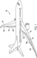
- FIG. 1 illustrates an aircraft 100 configured with flap mechanical systems that enable flap deflection during operation.
- the aircraft 100 includes two aircraft wings 102 with each wing 102 having multiple flaps labeled as a flap 104A, a flap 104B, and a flap 104C.
- each flap 104A-104C is connected to a flap mechanical system that is built into the aircraft wings 102 and can be used to reposition the flaps 104A-104C relative to the aircraft wing 102.
- the flap mechanical system 106 is outlined in Figure 1 to enable further description of how a mechanical system may be implemented and arranged to modify the position of the flap 104B on each aircraft wing 102.
- Flaps 104A, 104C can similarly have flap mechanical systems (not outlined), which may operate collectively with the flap mechanical system 106 and/or independently during aircraft operations.
- the aircraft 100 represents an example fixed-wing aircraft that may use flaps 104A-104C during operations, which can increase performance during takeoff and landing.
- the flaps 104A-104C When the flaps 104A-104C are positioned in an up orientation, the camber of the aircraft 100 enables the aircraft wings 102 to produce more lift.
- the flap 104B may extend to various degrees. For instance, the aircraft 100 may extend the flap 104B approximately 30 degrees during takeoff and 40 degrees during landing. After liftoff, the aircraft 100 may retract the flaps 104A-104C to avoid drag. As such, deploying the flaps 104A-104C can increase lift, which allows the aircraft 100 to climb during takeoff at slow speeds and also safely descend during landing also at slow speeds.
- aircraft computing devices may transmit signals to actuators positioned within the aircraft wings 102.
- the flap mechanical system 106 can include one or multiple flap actuators that generate force to adjust the setting of the flap 104B.
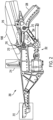
- the flap mechanical system 106 can incorporate the main flap support 200 illustrated in Figure 2 and Figure 3 , which can use an actuator 202 to extend or retract the flap 104B.
- the main flap support 200 represents a typical mechanical system that can be implemented on aircrafts to adjust the setting of a flap.
- the aircraft 100 can incorporate multiple main flap supports 200 into flap mechanical systems on the aircraft wings 102, including the flap mechanical systems 106 that enables deflection of the flaps 104B.
- the main flap support 200 is configured with an actuator 202 that can move a flap carriage 204 along a track 208.
- the main flap support 200 is secured at a fixed position to the aircraft wing 102 via coupling component 212 and coupling component 214 while the flap carriage 204 is coupled to the flap 104B at coupling points 216.
- the actuator 202 can then adjust the setting of the flap 104B relative to the aircraft wing 102 by changing the position of the flap carriage 204 on the track 208 via the trapped rollers 210 connecting the flap carriage 204 onto the track 208.
- the actuator 202 can be used to extend or retract the flap 104B, which adjusts the profile and surface area of the aircraft wing 102 to enable efficient flight at low airspeeds.
- the actuator 202 is a lead screw type of mechanism driven by an electric or hydraulic motor that can be activated to extend or retract the flap 104B based on signals received from an aircraft computing system.
- the track 208 is shown as a Pi-section beam built with a failsafe bar 304 as depicted in the cutaway view illustrated in Figure 3 .
- the Pi-section configuration enables trapped rollers 210 to rotate in the channels formed between the top surface and the bottom surface of the track 208, which allows the flap carriage 204 to change the setting of the flap 104B.
- the Pi-section configuration is difficult to manufacture due to the precise size and shape requirements to form the Pi-section.
- manufacturing the track 208 also requires additional time to produce and incorporate the failsafe bar 304. Machining the deep center slot in hardened steel of the track 208 for the failsafe bar 304 can be challenging. Fitting and installing the failsafe bar 304 into the slot formed in the track 208 also adds further complexity to the manufacturing process.
- the pins 302 for the trapped rollers 210 require a specific alignment in the flap carriage 204 to allow the trapped rollers 210 to smoothly rotate within the grooves of the Pi-section structure of the track 208. In some cases, this alignment might result in a jam that can damage operations of the main flap support 200.
- Flap mechanical systems can also incorporate auxiliary supports to supplement the actuators.
- Figure 4, Figure 5 , Figure 6, and Figure 7 illustrates different views of a flap assembly 400, which may be used to supplement one or more main flap supports 200 within a flap mechanical system (e.g., the flap mechanical system 106 associated with the flap 104B).
- the other flaps 104A, 104C shown on the aircraft wings 102 of the aircraft 100 can similarly be adjusted by flap mechanical systems that incorporate the disclosed flap assembly 400.
- the actuators 202 of the main flap supports 200 may supply the force to adjust the setting of the attached flap 104B while the flap assembly 400 provides additional support and stabilization to the flap 104B at the different settings.
- the flap assembly 400 includes a track 402 and a flap carriage 404 that is configured to move along the track 402 using a roller interface 410 similar to the main flap support 200.
- the flap assembly 400 is shown with a coupling component 412 for connecting the track 402 at a fixed position on an aircraft wing (e.g., built into the aircraft wing 102 of the aircraft 100) while the top portion 414 of the flap carriage 404 is configured to connect to the bottom surface of the flap 104B.
- the example configuration of the flap assembly 400 illustrated in Figures 4-7 represents one possible configuration.
- Other example configurations for the flap assembly 400 are possible.
- the sizes, the materials used (e.g., types of metals, alloys, and rubber), and the arrangement of the mechanical components of the flap assembly 400 can differ in other example embodiments.
- parameters of the track 402 and/or other components of the flap assembly 400 can vary based on the type of aircraft that incorporates the flap assembly 400.
- the flap assembly 400 can be used to provide support and alignment to a flap (e.g., the flap 104B) at different settings during aircraft operations. Unlike the main flap support 200, however, the flap assembly 400 lacks an actuator in the example embodiment and may therefore provide passive support that depends on actuation by other support systems (e.g., the actuator 202 of the main flap support 200) to adjust the position of the flap 104B.
- the flap mechanical system 106 can have two main flap supports 200 positioned near the ends of the flap 104B and the flap assembly 400 positioned in the middle of the flap 104B.
- the mechanical designs of the components of the flap assembly 400 decrease overall manufacturing complexity while also reducing vulnerability to potential jams that might arise during flap deflection.
- the combination of the track 402 and the roller interface 410 on the flap carriage 404 enable jam-resistant performance that can supplement actuators within flap mechanical systems.
- the track 402 is a support beam with an elongate structure that can be coupled to an aircraft wing (e.g., aircraft wing 102 of aircraft 100) at a fixed position via the coupling component 412 located on an upper portion of the track 208 and/or other different potential coupling mechanisms.
- These coupling components can have various forms within example embodiments.
- the track 402 is shown with a simple design, which is made up of sub-tracks 402A, 402B.
- Each sub-track 402A, 402B has a C-channel configuration, which results in the track 402 having a similar structure as the Pi-section configuration of the track 208 when the sub-tracks 402A, 402B are coupled together at seam 406 in a back-to-back configuration as further shown in Figure 5 and Figure 6 .
- sub-track 402A and sub-track 402B can be individually manufactured before being coupled together via one or more types of fasteners, such as bolts and screws, adhesives, welding, and/or a combination thereof.
- fasteners such as bolts and screws, adhesives, welding, and/or a combination thereof.
- each of the sub-tracks 402A, 402B have the physical properties to operate individually if needed, which increases crack resistance of the track 402 overall while also eliminating the need for a failsafe bar. This further reduces manufacturing complexity by eliminating a part (i.e., the failsafe bar) and additional steps during production of the track 402.
- the track 402 can be made out of various materials within example embodiments, such as metals and/or metallic alloys.
- parameters of the track 402 can depend on the type of aircraft 100 that is incorporating the flap assembly 400.
- the length 510 of the track 402 is greater than the width 512 of the track 402, which accommodates the structures of the aircraft wing 102 and the flap 104B.
- the length 510 and overall structure of the track 402 can allow deflection of the flap 104B at different settings used during aircraft operations.
- the track 402 is configured to couple to the aircraft wing 102 via the coupling component 412 such that the length 510 of the track 402 extends approximately parallel to a path of travel by the aircraft 100.
- the elongate structure of the track 402 includes a curved end 416 designed to enable deflection of the flap 104B relative to the aircraft wing 102.
- the flap carriage 404 can be moved along the curved end 416 of the track 402 to secure the flap 104B up to its full angular deflection relative to the aircraft wing 102 (e.g., up to 40 degrees).
- the flap carriage 404 is shown coupled to the track 402 and includes a roller interface 410 that enables the flap carriage 404 to move along a portion of the length 510 of the track 402.
- the flap 104B can rotate about the roller interface 410 while the roller interface 410 translates.
- the flap carriage 404 is a three piece back-to-back carriage, which increases durability of the flap carriage 404 overall while also reducing the complexity of manufacturing the flap carriage 404.
- Figure 6 and Figure 7 illustrate the combination of a side portion 610A, a middle portion 610B, and another side portion 610C that are coupled together to form the flap carriage 404.
- Each of the side portions 610A, 610C has an L-shape configuration while the middle portion 610B is shown with an inverted U-channel configuration.
- the three portions can be coupled together via one or more types of fasteners to form the flap carriage 404.
- the side portion 610A is coupled to the middle portion 610B forming seam 612 and the side portion 610C is coupled to the opposite side of the middle portion 610B forming seam 614.
- This three-portion configuration for the flap carriage 404 reduces the manufacturing complexity of the flap carriage 404.
- the inverted U-channel of the middle portion 610B can be structured to securely fit around the track 402 with minor gaps 620 that enables the flap carriage 404 to move along a portion of the length 510 of the track 402 as the track 402 operates as the support beam for the flap assembly 400.
- the components of the flap carriage 404 can be created via additive manufacturing or another type of manufacturing process.
- the top portion 414 of the flap carriage 404 is shown coupled to the flap 104B such that movement of the flap carriage 104 along the length 510 of the track enables movement of the flap 104B relative to the aircraft wing 102.
- the top portion 414 can be connected via one or more types of fasteners, such as bolts, screws, adhesives, etc.
- the roller interface 410 coupled into the flap carriage 404 enables the flap carriage 404 to adjust position on the track 402.
- the roller interface 410 includes a primary roller 602 and a pair of secondary rollers 604A, 604B, which are all positioned within the inverted U-channel of the middle portion 610B of the flap carriage 404.
- the track 402 is configured to be positioned in the inverted U-channel of the middle portion 610B such that a bottom surface 712 of the track 402 engages the primary roller 602 (e.g., sits on top of the primary roller 602) and the grooves in the C-channel of each sub-track 402A, 402B are aligned relative to the pair of secondary rollers 604A, 604B, respectively.
- This enables the secondary rollers 604A, 606B to rotate within the grooves in the outward-facing C-channels of the track 402 while the bottom surface 712 of the track 402 moves along with assistance from the primary rollers 602.
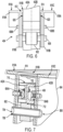
- the cut away view of the flap assembly 400 shown in Figure 7 depicts the secondary roller 604A positioned in the groove of the C-channel formed in sub-track 402A and the secondary roller 604B positioned in the groove of the C-channel formed in the sub-track 402B.
- the secondary rollers 604A-604B can rotate in the grooves of the C-channels that are part of the track 402 while the primary roller 602 provides support and enables movement of the flap carriage 404 along the track 402.
- the roller interface 410 of the flap carriage 404 differs from the rollers 210 of the flap carriage 204 of the main flap support 200.
- the primary roller 602 and the pair of secondary rollers 604A, 604B are arranged to reduce potential jams during movement of the flap carriage 404 along the track 402.
- the primary roller 602 is shown positioned below the track 402, which enables potential foreign object debris to fall out of the flap carriage 404 rather than causing potential jams.
- the secondary rollers 604A, 604B can be implemented using dead weight rollers designed with pins 608A, 608B that are able to fuse when the associated secondary roller 604A, 604B encounters any web or flange jam.
- the primary roller 602 is positioned on a pin 606.
- the secondary roller 604A is shown positioned on a pin 608A and the secondary roller 604B is shown positioned on a pin 608B.
- the secondary rollers 604A-604B can be implemented as two dead weight rollers.
- the pin 606 of the primary roller 602 positions the primary roller 602 in the inverted U-channel of the middle portion 610B and is shown extending from the side portion 610A to the side portion 610C.
- the pin 606 is shown positioned near the bottom end 616B of the side portion 610A (opposite the top side 616A of the side portion 610A) and near the bottom end 618B of the side portion 610C (opposite the top side 618A of the side portion 610C).
- the primary roller 602 can rotate with respect to the bottom surface 712 of the track 402.
- the primary roller 602 is an air-loaded roller to further support the track 402 during movement of the flap carriage 404.
- the secondary roller 604A is positioned on an inner surface and near the middle of the side portion 610A and the secondary roller 604B positioned on an inner surface and near the middle of the side portion 610C.
- This enables the secondary rollers 604A, 604B to be positioned in a manner that extend toward each other in an alignment on a given plane.
- the secondary roller 604A is configured to couple to a first side of the track 402 (i.e., the inner groove of the C-channel of sub-track 402A) and the secondary roller 604B is configured to couple to a second side of the track 402 (i.e., the inner groove of the C-channel of the sub-track 402B).
- the secondary rollers 604A, 604B are shown arranged in a redundant configuration to further enhance performance of the flap assembly 400.
- Figure 7 also further shows that the flap carriage 404 includes an inner pad 702 configured to protect the top surface 710 of the track 402.
- the inner pad 702 can engage and protect the track 402 if a malfunction occurs at one or both of the pair of secondary rollers 604A, 604B.
- the inner pad 702 is configured to act as a load path in the event the flap 104B and track 402 contact.
- the secondary rollers 604A, 604B can be dead weight rollers in some embodiments. The dead weight rollers can take minor flap loads while taxiing on the runway. By using two deadweight rollers, the remaining roller takes limit load until the next maintenance check.
- the inner pad 702 provides cushion to the top surface 710 of the track 402 to continue normal operation. This failure may likely cause a flap misfair (e.g., misalignment due to component failure) that is visible during any inspection of the aircraft.
- the pin 606 of the primary can have a pin-in-pin configuration made up of interior pin 704 and exterior pin 706, which increases durability of the pin 606 and the primary roller 602 for fail safety.
- the pin-in-pin configuration of the pin 606 allows either of the interior pin 704 and the exterior pin 706 to take limit load if other pin cracks. This increases overall durability of the primary roller 602 during operations.
Landscapes
- Engineering & Computer Science (AREA)
- Aviation & Aerospace Engineering (AREA)
- Transmission Devices (AREA)
- Mechanical Engineering (AREA)
- Automation & Control Theory (AREA)
Abstract
Description
- The present disclosure relates generally to mechanical systems for securing and stabilizing aircraft wing flaps, and more particularly to auxiliary flap assemblies that are simple to manufacture and configured with failsafe jam-resistant flap tracks.
- A flap is a high lift device typically consisting of a hinged panel or panels mounted on an aircraft wing, such as the trailing edge of the wing. The flap's setting (e.g., the position and orientation of the flap relative to the wing) can be adjusted to increase the camber and, in some applications, the chord and surface area of the wing. The wing's camber can indicate the convexity of the upper part of the wing and the concavity of the lower part of the wing. Extending flaps during flight can increase lift and drag while also reducing stall speed, which can improve the aircraft's performance during takeoffs and landings. During a landing, the extended flaps enable the aircraft to travel at lower landing speeds that can reduce the length of the landing strip required. Extended flaps can also increase drag, which enables the aircraft to steepen its descent angle without increasing overall airspeed.
- The configurations of the flaps can vary across different types of aircrafts. For instance, large jetliners are often designed with flaps that have multiple portions (e.g., three part flaps) while smaller aircrafts have appropriately sized flaps that attach to the wings via hinges. To adjust the settings of the flaps, flap mechanical systems are built into the wings, which can include actuators to extend or retract the flaps to effectively change the profiles and surface areas of wings. In addition to the actuators, flap mechanical systems can also incorporate auxiliary support structures can help stabilize and align the flaps during different settings.
- In one example, a flap assembly is described. The flap assembly includes a track having an elongate structure. The track is configured to couple to an aircraft wing. The flap assembly also includes a flap carriage configured to move along a length of the track. The flap carriage includes a primary roller and a pair of secondary rollers configured to secure the flap carriage to the track. A top portion of the flap carriage is configured to couple to a flap such that movement of the flap carriage along the length of the track enables movement of the flap relative to the aircraft wing.
- In another example, a system is described. The system includes a flap and a flap assembly. The flap assembly includes a track having an elongate structure and a flap carriage configured to move along a length of the track. The track is configured to couple to an aircraft wing. The flap carriage includes a primary roller and a pair of secondary rollers configured to secure the flap carriage to the track. A top portion of the flap carriage is configured to couple to the flap such that movement of the flap carriage along the length of the track enables movement of the flap relative to the aircraft wing.
- In an additional example, an aircraft is described. The aircraft includes an aircraft wing and a flap coupled to the aircraft wing via a flap assembly. The flap assembly includes a track having an elongate structure and a flap carriage configured to move along a length of the track. The track is configured to couple to an aircraft wing. The flap carriage includes a primary roller and a pair of secondary rollers configured to secure the flap carriage to the track. A top portion of the flap carriage is configured to couple to the flap such that movement of the flap carriage along the length of the track enables movement of the flap relative to the aircraft wing.
- The features, functions, and advantages that have been discussed can be achieved independently in various examples or may be combined in yet other examples further details of which can be seen with reference to the following description and drawings.
- The novel features believed characteristic of the illustrative examples are set forth in the appended claims. The illustrative examples, however, as well as a preferred mode of use, further objectives and descriptions thereof, will best be understood by reference to the following detailed description of an illustrative example of the present disclosure when read in conjunction with the accompanying drawings, wherein:
-
Figure 1 illustrates a fixed-wing aircraft with flap mechanical systems, according to an example implementation. -
Figure 2 illustrates a main flap support, according to an example implementation. -
Figure 3 illustrates a cut away view of the flap assembly and the track shown inFigure 2 , according to an example implementation. -
Figure 4 illustrates an auxiliary flap assembly configured with a jam-resistant track, according to an example implementation. -
Figure 5 illustrates another view of the flap assembly shown inFigure 4 , according to an example implementation. -
Figure 6 illustrates a different view of the flap assembly shown inFigure 4 and Figure 5 , according to an example implementation. -
Figure 7 illustrates a cut-away view of the flap assembly shown inFigures 4-6 , according to an example implementation. - Disclosed examples will now be described more fully hereinafter with reference to the accompanying drawings, in which some, but not all of the disclosed examples are shown. Indeed, several different examples may be described and should not be construed as limited to the examples set forth herein. Rather, these examples are described so that this disclosure will be thorough and complete and will fully convey the scope of the disclosure to those skilled in the art.
- Example embodiments relate to different configurations of a flap assembly with a jam resistant flap track. Aircrafts can incorporate disclosed flap assemblies within flap mechanical systems to use for auxiliary stabilization and support for flaps in addition to the actuators that extend or retract the flaps. The disclosed flap assemblies are designed with mechanical features that reduce manufacturing complexity while also increasing resistance to potential jams during operation. As an example result, an aircraft's flap mechanical systems can incorporate disclosed flap assemblies instead of alternative options that are typically prone to jams and can cost more time and resources to manufacture. Jams can also drive additional cost and weight to the final design of the aircraft, which impacts customers that use the aircraft. Flaps that are not prone to jam can result in lower maintenance costs during normal operation. For instance, a flap mechanical system can use two actuators positioned near the ends of a flap and one or more disclosed flap assemblies positioned in between the actuators to provide further stabilization and alignment during flap deflection.
- Referring now to the Figures,
Figure 1 illustrates anaircraft 100 configured with flap mechanical systems that enable flap deflection during operation. In the example embodiment, theaircraft 100 includes twoaircraft wings 102 with eachwing 102 having multiple flaps labeled as aflap 104A, aflap 104B, and aflap 104C. In order to enable computing devices on theaircraft 100 to adjust theflaps 104A-104C during operations, eachflap 104A-104C is connected to a flap mechanical system that is built into theaircraft wings 102 and can be used to reposition theflaps 104A-104C relative to theaircraft wing 102. For illustration purposes, the flapmechanical system 106 is outlined inFigure 1 to enable further description of how a mechanical system may be implemented and arranged to modify the position of theflap 104B on eachaircraft wing 102.Flaps mechanical system 106 and/or independently during aircraft operations. - The
aircraft 100 represents an example fixed-wing aircraft that may useflaps 104A-104C during operations, which can increase performance during takeoff and landing. When theflaps 104A-104C are positioned in an up orientation, the camber of theaircraft 100 enables theaircraft wings 102 to produce more lift. Depending on theaircraft 100, theflap 104B may extend to various degrees. For instance, theaircraft 100 may extend theflap 104B approximately 30 degrees during takeoff and 40 degrees during landing. After liftoff, theaircraft 100 may retract theflaps 104A-104C to avoid drag. As such, deploying theflaps 104A-104C can increase lift, which allows theaircraft 100 to climb during takeoff at slow speeds and also safely descend during landing also at slow speeds. - To adjust the settings of the
flaps 104A-104C, aircraft computing devices may transmit signals to actuators positioned within theaircraft wings 102. For instance, the flapmechanical system 106 can include one or multiple flap actuators that generate force to adjust the setting of theflap 104B. As an example embodiment, the flapmechanical system 106 can incorporate themain flap support 200 illustrated inFigure 2 andFigure 3 , which can use anactuator 202 to extend or retract theflap 104B. - As shown in
Figure 2 andFigure 3 , themain flap support 200 represents a typical mechanical system that can be implemented on aircrafts to adjust the setting of a flap. For instance, theaircraft 100 can incorporate multiple main flap supports 200 into flap mechanical systems on theaircraft wings 102, including the flapmechanical systems 106 that enables deflection of theflaps 104B. In the example embodiment, themain flap support 200 is configured with anactuator 202 that can move aflap carriage 204 along atrack 208. In practice, themain flap support 200 is secured at a fixed position to theaircraft wing 102 viacoupling component 212 andcoupling component 214 while theflap carriage 204 is coupled to theflap 104B at coupling points 216. With this arrangement, theactuator 202 can then adjust the setting of theflap 104B relative to theaircraft wing 102 by changing the position of theflap carriage 204 on thetrack 208 via the trappedrollers 210 connecting theflap carriage 204 onto thetrack 208. For instance, theactuator 202 can be used to extend or retract theflap 104B, which adjusts the profile and surface area of theaircraft wing 102 to enable efficient flight at low airspeeds. In some embodiments, theactuator 202 is a lead screw type of mechanism driven by an electric or hydraulic motor that can be activated to extend or retract theflap 104B based on signals received from an aircraft computing system. - The
track 208 is shown as a Pi-section beam built with afailsafe bar 304 as depicted in the cutaway view illustrated inFigure 3 . The Pi-section configuration enables trappedrollers 210 to rotate in the channels formed between the top surface and the bottom surface of thetrack 208, which allows theflap carriage 204 to change the setting of theflap 104B. The Pi-section configuration, however, is difficult to manufacture due to the precise size and shape requirements to form the Pi-section. In addition, manufacturing thetrack 208 also requires additional time to produce and incorporate thefailsafe bar 304. Machining the deep center slot in hardened steel of thetrack 208 for thefailsafe bar 304 can be challenging. Fitting and installing thefailsafe bar 304 into the slot formed in thetrack 208 also adds further complexity to the manufacturing process. - Furthermore, the
pins 302 for the trappedrollers 210 require a specific alignment in theflap carriage 204 to allow the trappedrollers 210 to smoothly rotate within the grooves of the Pi-section structure of thetrack 208. In some cases, this alignment might result in a jam that can damage operations of themain flap support 200. - Flap mechanical systems can also incorporate auxiliary supports to supplement the actuators.
Figure 4, Figure 5 ,Figure 6, and Figure 7 illustrates different views of aflap assembly 400, which may be used to supplement one or more main flap supports 200 within a flap mechanical system (e.g., the flapmechanical system 106 associated with theflap 104B). The other flaps 104A, 104C shown on theaircraft wings 102 of theaircraft 100 can similarly be adjusted by flap mechanical systems that incorporate the disclosedflap assembly 400. In practice, theactuators 202 of the main flap supports 200 (or similar devices) may supply the force to adjust the setting of the attachedflap 104B while theflap assembly 400 provides additional support and stabilization to theflap 104B at the different settings. - The different views of the disclosed
flap assembly 400 illustrated inFigures 4-7 show the mechanical features of theflap assembly 400. In the example embodiment, theflap assembly 400 includes atrack 402 and aflap carriage 404 that is configured to move along thetrack 402 using aroller interface 410 similar to themain flap support 200. In addition, theflap assembly 400 is shown with acoupling component 412 for connecting thetrack 402 at a fixed position on an aircraft wing (e.g., built into theaircraft wing 102 of the aircraft 100) while thetop portion 414 of theflap carriage 404 is configured to connect to the bottom surface of theflap 104B. - As such, the example configuration of the
flap assembly 400 illustrated inFigures 4-7 represents one possible configuration. Other example configurations for theflap assembly 400 are possible. For instance, the sizes, the materials used (e.g., types of metals, alloys, and rubber), and the arrangement of the mechanical components of theflap assembly 400 can differ in other example embodiments. For instance, parameters of thetrack 402 and/or other components of theflap assembly 400 can vary based on the type of aircraft that incorporates theflap assembly 400. - Similar to the
main flap support 200 shown inFigures 2-3 , theflap assembly 400 can be used to provide support and alignment to a flap (e.g., theflap 104B) at different settings during aircraft operations. Unlike themain flap support 200, however, theflap assembly 400 lacks an actuator in the example embodiment and may therefore provide passive support that depends on actuation by other support systems (e.g., theactuator 202 of the main flap support 200) to adjust the position of theflap 104B. For example, the flapmechanical system 106 can have two main flap supports 200 positioned near the ends of theflap 104B and theflap assembly 400 positioned in the middle of theflap 104B. - The mechanical designs of the components of the
flap assembly 400 decrease overall manufacturing complexity while also reducing vulnerability to potential jams that might arise during flap deflection. In practice, the combination of thetrack 402 and theroller interface 410 on theflap carriage 404 enable jam-resistant performance that can supplement actuators within flap mechanical systems. Similar to thetrack 208 of themain flap support 200, thetrack 402 is a support beam with an elongate structure that can be coupled to an aircraft wing (e.g.,aircraft wing 102 of aircraft 100) at a fixed position via thecoupling component 412 located on an upper portion of thetrack 208 and/or other different potential coupling mechanisms. These coupling components can have various forms within example embodiments. Further, unlike the Pi-section configuration of thetrack 208, thetrack 402 is shown with a simple design, which is made up ofsub-tracks track 402 having a similar structure as the Pi-section configuration of thetrack 208 when the sub-tracks 402A, 402B are coupled together atseam 406 in a back-to-back configuration as further shown inFigure 5 andFigure 6 . - In addition, unlike the Pi-section configuration of the
track 208, sub-track 402A and sub-track 402B can be individually manufactured before being coupled together via one or more types of fasteners, such as bolts and screws, adhesives, welding, and/or a combination thereof. As an example result, each of the sub-tracks 402A, 402B have the physical properties to operate individually if needed, which increases crack resistance of thetrack 402 overall while also eliminating the need for a failsafe bar. This further reduces manufacturing complexity by eliminating a part (i.e., the failsafe bar) and additional steps during production of thetrack 402. - The
track 402 can be made out of various materials within example embodiments, such as metals and/or metallic alloys. In addition, parameters of thetrack 402 can depend on the type ofaircraft 100 that is incorporating theflap assembly 400. As shown inFigure 5 , thelength 510 of thetrack 402 is greater than thewidth 512 of thetrack 402, which accommodates the structures of theaircraft wing 102 and theflap 104B. Thelength 510 and overall structure of thetrack 402 can allow deflection of theflap 104B at different settings used during aircraft operations. In practice, thetrack 402 is configured to couple to theaircraft wing 102 via thecoupling component 412 such that thelength 510 of thetrack 402 extends approximately parallel to a path of travel by theaircraft 100. - As further shown in
Figure 4 , the elongate structure of thetrack 402 includes acurved end 416 designed to enable deflection of theflap 104B relative to theaircraft wing 102. In response to actuation from themain flap support 200, theflap carriage 404 can be moved along thecurved end 416 of thetrack 402 to secure theflap 104B up to its full angular deflection relative to the aircraft wing 102 (e.g., up to 40 degrees). - The
flap carriage 404 is shown coupled to thetrack 402 and includes aroller interface 410 that enables theflap carriage 404 to move along a portion of thelength 510 of thetrack 402. Theflap 104B can rotate about theroller interface 410 while theroller interface 410 translates. In the example embodiment shown inFigures 4-7 , theflap carriage 404 is a three piece back-to-back carriage, which increases durability of theflap carriage 404 overall while also reducing the complexity of manufacturing theflap carriage 404. In particular,Figure 6 and Figure 7 illustrate the combination of aside portion 610A, amiddle portion 610B, and anotherside portion 610C that are coupled together to form theflap carriage 404. Each of theside portions middle portion 610B is shown with an inverted U-channel configuration. The three portions can be coupled together via one or more types of fasteners to form theflap carriage 404. In particular, theside portion 610A is coupled to themiddle portion 610B forming seam 612 and theside portion 610C is coupled to the opposite side of themiddle portion 610B forming seam 614. - This three-portion configuration for the
flap carriage 404 reduces the manufacturing complexity of theflap carriage 404. In addition, the inverted U-channel of themiddle portion 610B can be structured to securely fit around thetrack 402 withminor gaps 620 that enables theflap carriage 404 to move along a portion of thelength 510 of thetrack 402 as thetrack 402 operates as the support beam for theflap assembly 400. In some embodiments, the components of theflap carriage 404 can be created via additive manufacturing or another type of manufacturing process. - The
top portion 414 of theflap carriage 404 is shown coupled to theflap 104B such that movement of the flap carriage 104 along thelength 510 of the track enables movement of theflap 104B relative to theaircraft wing 102. As such, thetop portion 414 can be connected via one or more types of fasteners, such as bolts, screws, adhesives, etc. - The
roller interface 410 coupled into theflap carriage 404 enables theflap carriage 404 to adjust position on thetrack 402. As shown in the example embodiment, theroller interface 410 includes aprimary roller 602 and a pair ofsecondary rollers middle portion 610B of theflap carriage 404. When theflap assembly 400 is installed, thetrack 402 is configured to be positioned in the inverted U-channel of themiddle portion 610B such that abottom surface 712 of thetrack 402 engages the primary roller 602 (e.g., sits on top of the primary roller 602) and the grooves in the C-channel of each sub-track 402A, 402B are aligned relative to the pair ofsecondary rollers secondary rollers 604A, 606B to rotate within the grooves in the outward-facing C-channels of thetrack 402 while thebottom surface 712 of thetrack 402 moves along with assistance from theprimary rollers 602. - To further illustrate, the cut away view of the
flap assembly 400 shown inFigure 7 depicts thesecondary roller 604A positioned in the groove of the C-channel formed in sub-track 402A and thesecondary roller 604B positioned in the groove of the C-channel formed in the sub-track 402B. In such positions, thesecondary rollers 604A-604B can rotate in the grooves of the C-channels that are part of thetrack 402 while theprimary roller 602 provides support and enables movement of theflap carriage 404 along thetrack 402. - The
roller interface 410 of theflap carriage 404 differs from therollers 210 of theflap carriage 204 of themain flap support 200. As shown in the example embodiment, theprimary roller 602 and the pair ofsecondary rollers flap carriage 404 along thetrack 402. Theprimary roller 602 is shown positioned below thetrack 402, which enables potential foreign object debris to fall out of theflap carriage 404 rather than causing potential jams. In addition, thesecondary rollers pins secondary roller - To secure the
primary roller 602 in position in the inverted U-channel of theflap carriage 404, theprimary roller 602 is positioned on apin 606. In addition, thesecondary roller 604A is shown positioned on apin 608A and thesecondary roller 604B is shown positioned on apin 608B. In some embodiments, thesecondary rollers 604A-604B can be implemented as two dead weight rollers. - The
pin 606 of theprimary roller 602 positions theprimary roller 602 in the inverted U-channel of themiddle portion 610B and is shown extending from theside portion 610A to theside portion 610C. In addition, thepin 606 is shown positioned near thebottom end 616B of theside portion 610A (opposite thetop side 616A of theside portion 610A) and near thebottom end 618B of theside portion 610C (opposite thetop side 618A of theside portion 610C). At this position, theprimary roller 602 can rotate with respect to thebottom surface 712 of thetrack 402. In some examples, theprimary roller 602 is an air-loaded roller to further support thetrack 402 during movement of theflap carriage 404. - As further shown, the
secondary roller 604A is positioned on an inner surface and near the middle of theside portion 610A and thesecondary roller 604B positioned on an inner surface and near the middle of theside portion 610C. This enables thesecondary rollers secondary roller 604A is configured to couple to a first side of the track 402 (i.e., the inner groove of the C-channel of sub-track 402A) and thesecondary roller 604B is configured to couple to a second side of the track 402 (i.e., the inner groove of the C-channel of the sub-track 402B). Thesecondary rollers flap assembly 400. - In addition,
Figure 7 also further shows that theflap carriage 404 includes aninner pad 702 configured to protect thetop surface 710 of thetrack 402. For instance, theinner pad 702 can engage and protect thetrack 402 if a malfunction occurs at one or both of the pair ofsecondary rollers inner pad 702 is configured to act as a load path in the event theflap 104B and track 402 contact. Thesecondary rollers secondary rollers inner pad 702 provides cushion to thetop surface 710 of thetrack 402 to continue normal operation. This failure may likely cause a flap misfair (e.g., misalignment due to component failure) that is visible during any inspection of the aircraft. As further shown inFigure 7 , thepin 606 of the primary can have a pin-in-pin configuration made up ofinterior pin 704 andexterior pin 706, which increases durability of thepin 606 and theprimary roller 602 for fail safety. The pin-in-pin configuration of thepin 606 allows either of theinterior pin 704 and theexterior pin 706 to take limit load if other pin cracks. This increases overall durability of theprimary roller 602 during operations. - The disclosure comprises the subject matter described in the following examples:
- Example 1. A flap assembly comprising: a track having an elongate structure, wherein the track is configured to couple to an aircraft wing; and a flap carriage configured to move along a length of the track, wherein the flap carriage includes a primary roller and a pair of secondary rollers configured to secure the flap carriage to the track, and wherein a top portion of the flap carriage is configured to couple to a flap such that movement of the flap carriage along the length of the track enables movement of the flap relative to the aircraft wing.
- Example 2. The flap assembly of example 1, wherein the flap carriage includes an inverted U-channel formed by the top portion and side portions of the flap carriage, and wherein the primary roller and the pair of secondary rollers are positioned inside the inverted U-channel.
- Example 3. The flap assembly of example 2, wherein the side portions of the flap carriage include a first side portion having a first end and a second end and a second side portion having a first end and a second end, wherein the first end of the first side portion and the first end of the second side portion are coupled to the top portion of the flap carriage, wherein a pin of the primary roller extends through the first side portion proximate the second end of the second side portion and the second side portion proximate the second end of the second side portion, and wherein a position of the pin of the primary roller enables the primary roller to couple to a bottom surface of the track.
- Example 4. The flap assembly of example 3, wherein the pin of the primary roller comprises a pin-in-pin configuration.
- Example 5. The flap assembly of example 3 or 4, wherein the pair of secondary rollers comprises: a first secondary roller positioned on an inner surface of the first side portion proximate a middle portion of the first side portion, and a second secondary roller positioned on an inner surface of the second side portion proximate a middle portion of the second side portion.
- Example 6. The flap assembly of example 5, wherein the first secondary roller and the second secondary roller are aligned on a given plane, and wherein first secondary roller is configured to couple to a first side of the track and the second secondary roller is configured to couple to a second side of the track.
- Example 7. The flap assembly of any of examples 1-6, wherein the track comprises a first sub-track having a C-channel configuration and a second sub-track having the C-channel configuration, and wherein the first sub-track and the second sub-track are coupled together in a back-to-back configuration.
- Example 8. The flap assembly of example 7, wherein each secondary roller in the pair of secondary rollers is configured to couple to an inner portion of the C-channel configuration of a given sub-track.
- Example 9. The flap assembly of any of examples 1-8, wherein the flap carriage further includes an inner pad configured to protect a top surface of the track in response to a malfunction at one or both of the pair of secondary rollers.
- Example 10. The flap assembly of any of examples 1-9, wherein the primary roller further includes an air-loaded roller.
- Example 11. The flap assembly of any of examples 1-10, wherein the pair of secondary rollers comprises two dead weight rollers arranged in a redundant configuration.
- Example 12. The flap assembly of any of examples 1-11, wherein the flap carriage is a three piece back-to-back carriage.
- Example 13. The flap assembly of any of examples 1-12, wherein an upper portion of the track is configured to couple to a bottom surface of the aircraft wing.
- Example 14. The flap assembly of any of examples 1-13, wherein a length of the track is greater than a width of the track, and wherein the track is configured to couple to the aircraft wing such that the length of the track extends parallel to a path of travel by the aircraft.
- Example 15. The flap assembly of any of examples 1-14, wherein the elongate structure of the track includes a curved end, and wherein movement of the flap carriage along the curved end of the track enables the flap to move in a downward angle relative to the aircraft wing.
- Example 16. A system comprising: a flap; and a flap assembly comprising: a track having an elongate structure, wherein the track is configured to couple to an aircraft wing; and a flap carriage configured to move along a length of the track, wherein the flap carriage includes a primary roller and a pair of secondary rollers configured to secure the flap carriage to the track, and wherein a top portion of the flap carriage is configured to couple to the flap such that movement of the flap carriage along the length of the track enables movement of the flap relative to the aircraft wing.
- Example 16a. A system comprising: a flap; and the flap assembly of any of examples 1 to 15, wherein the top portion of the flap carriage is configured to couple to the flap such that movement of the flap carriage along the length of the track enables movement of the flap relative to the aircraft wing.
- Example 17. The system of example 16 or 16a, wherein the track comprises a first sub-track having a C-channel configuration and a second sub-track having the C-channel configuration, and wherein the first sub-track and the second sub-track are coupled together in a back-to-back configuration.
- Example 18. The system of example 17, wherein each secondary roller in the pair of secondary rollers is configured to couple to an inner portion of the C-channel configuration of a given sub-track.
- Example 19. The system of any of examples 16-18, further comprising: at least one main flap support coupled to the flap, wherein the at least one main flap support includes an actuator configured to provide power to move the flap; and wherein the flap carriage moves along the track in response to the actuator providing power to move the flap.
- Example 20. An aircraft comprising: an aircraft wing; a flap coupled to the aircraft wing via a flap assembly comprising: a track having an elongate structure, wherein the track is coupled to the aircraft wing; and a flap carriage configured to move along a length of the track, wherein the flap carriage includes a primary roller and a pair of secondary rollers configured to secure the flap carriage to the track, and wherein a top portion of the flap carriage is coupled to the flap, wherein movement of the flap carriage along the length of the track causes the flap to move relative to the aircraft wing.
- Example 21. An aircraft comprising: an aircraft wing; a flap coupled to the aircraft wing; and the flap assembly of any of examples 1 to 15, wherein: the flap is coupled to the aircraft wing via the flap assembly; the track of the flap assembly is coupled to the aircraft wing; the top portion of the flap carriage is coupled to the flap; and movement of the flap carriage along the length of the track causes the flap to move relative to the aircraft wing.
- By the term "substantially" or "about" used herein, it is meant that the recited characteristic, parameter, or value need not be achieved exactly, but that deviations or variations, including for example, measurement error, measurement accuracy limitations, friction, and other factors known to skill in the art, may occur in amounts that do not preclude and/or occlude the effect the characteristic was intended to provide.
- The description of the different advantageous arrangements has been presented for purposes of illustration and description, and is not intended to be exhaustive or limited to the examples in the form disclosed. Many modifications and variations will be apparent to those of ordinary skill in the art. Further, different advantageous examples may describe different advantages as compared to other advantageous examples. The example or examples selected are chosen and described in order to best explain the principles of the examples, the practical application, and to enable others of ordinary skill in the art to understand the disclosure for various examples with various modifications as are suited to the particular use contemplated.
Claims (15)
- A flap assembly (400) comprising:a track (208, 402) having an elongate structure, wherein the track (208, 402) is configured to couple to an aircraft wing (102); anda flap carriage (204, 404) configured to move along a length (510) of the track (208, 402), wherein the flap (204, 404) carriage includes a primary roller (602) and a pair of secondary rollers (604A, 604B) configured to secure the flap carriage (204, 404) to the track (208, 402), and wherein a top portion (414) of the flap carriage (204, 404) is configured to couple to a flap (104A, 104A-104C, 104B, 104C) such that movement of the flap carriage (204, 404) along the length (510) of the track (208, 402) enables movement of the flap (104A, 104A-104C, 104B, 104C) relative to the aircraft wing (102).
- The flap assembly (400) of claim 1, wherein the flap carriage (204, 404) includes an inverted U-channel formed by the top portion (414) and side portions (610A, 610C) of the flap carriage (204, 404), and
wherein the primary roller (602) and the pair of secondary rollers (604A, 604B) are positioned inside the inverted U-channel. - The flap assembly (400) of claim 2, wherein the side portions (610A, 610C) of the flap carriage (204, 404) include a first side portion (610A, 610C) having a first end and a second end and a second side portion (610A, 610C) having a first end and a second end,wherein the first end of the first side portion (610A, 610C) and the first end of the second side portion (610A, 610C) are coupled to the top portion (414) of the flap carriage (204, 404),wherein a pin (606, 608A, 608B) of the primary roller (602) extends through the first side portion (610A, 610C) proximate the second end of the second side portion (610A, 610C) and the second side portion (610A, 610C) proximate the second end of the second side portion (610A, 610C), andwherein a position of the pin (606, 608A, 608B) of the primary roller (602) enables the primary roller (602) to couple to a bottom surface (712) of the track (208, 402).
- The flap assembly (400) of claim 3, wherein the pin (606, 608A, 608B) of the primary roller (602) comprises a pin-in-pin configuration.
- The flap assembly (400) of claim 3 or 4, wherein the pair of secondary rollers (604A, 604B) comprises:a first secondary roller (604A, 604B) positioned on an inner surface of the first side portion (610A, 610C) proximate a middle portion (610B) of the first side portion (610A, 610C), anda second secondary roller (604A, 604B) positioned on an inner surface of the second side portion (610A, 610C) proximate a middle portion (610B) of the second side portion (610A, 610C).
- The flap assembly (400) of any of claims 3 to 5, wherein the first secondary roller (604A, 604B) and the second secondary roller (604A, 604B) are aligned on a given plane, and
wherein first secondary roller (604A, 604B) is configured to couple to a first side of the track (208, 402) and the second secondary roller (604A, 604B) is configured to couple to a second side of the track (208, 402). - The flap assembly (400) of any of claims 1-6, wherein the track (208, 402) comprises a first sub-track (208, 402) having a C-channel configuration and a second sub-track (208, 402) having the C-channel configuration, and
wherein the first sub-track (208, 402) and the second sub-track (208, 402) are coupled together in a back-to-back configuration. - The flap assembly (400) of claim 7, wherein each secondary roller (604A, 604B) in the pair of secondary rollers (604A, 604B) is configured to couple to an inner portion of the C-channel configuration of a given sub-track (208, 402).
- The flap assembly (400) of any of claims 1-8, wherein the flap carriage (204, 404) further includes an inner pad (702) configured to protect a top surface (710) of the track (208, 402) in response to a malfunction at one or both of the pair of secondary rollers (604A, 604B).
- The flap assembly (400) of any of claims 1-9, wherein the pair of secondary rollers (604A, 604B) comprises two dead weight rollers (210) arranged in a redundant configuration.
- The flap assembly (400) of any of claims 1-10, wherein an upper portion of the track (208, 402) is configured to couple to a bottom surface (712) of the aircraft wing (102).
- The flap assembly (400) of any of claims 1-11, wherein the elongate structure of the track (208, 402) includes a curved end (416), and
wherein movement of the flap carriage (204, 404) along the curved end (416) of the track (208, 402) enables the flap (104A, 104A-104C, 104B, 104C) to move in a downward angle relative to the aircraft wing (102). - A system comprising:a flap (104A, 104A-104C, 104B, 104C); andthe flap assembly (400) of any preceding claim, wherein the top portion (414) of the flap carriage (204, 404) is configured to couple to the flap (104A, 104A-104C, 104B, 104C) such that movement of the flap carriage (204, 404) along the length (510) of the track (208, 402) enables movement of the flap (104A, 104A-104C, 104B, 104C) relative to the aircraft wing (102).
- The system of claim 13, further comprising:at least one main flap support (200) coupled to the flap (104A, 104A-104C, 104B, 104C), wherein the at least one main flap support includes an actuator (202) configured to provide power to move the flap; andwherein the flap carriage (204, 404) moves along the track (208, 402) in response to the actuator (202) providing power to move the flap (104A, 104A-104C, 104B, 104C).
- An aircraft (100) comprising:an aircraft wing (102);a flap (104A, 104A-104C, 104B, 104C) coupled to the aircraft wing (102); andthe flap assembly (400) of any of claims 1 to 12, wherein:the flap (104A, 104A-104C, 104B, 104C) is coupled to the aircraft wing (102) via the flap assembly (400);the track (208, 402) of the flap assembly (400) is coupled to the aircraft wing (102);the top portion (414) of the flap carriage (204, 404) is coupled to the flap (104A, 104A-104C, 104B, 104C); andmovement of the flap carriage (204, 404) along the length (510) of the track (208, 402) causes the flap (104A, 104A-104C, 104B, 104C) to move relative to the aircraft wing (102).
Applications Claiming Priority (1)
| Application Number | Priority Date | Filing Date | Title |
|---|---|---|---|
| US17/656,376 US11834178B2 (en) | 2022-03-24 | 2022-03-24 | Flap assemblies with failsafe jam-resistant flap tracks |
Publications (2)
| Publication Number | Publication Date |
|---|---|
| EP4249372A1 true EP4249372A1 (en) | 2023-09-27 |
| EP4249372B1 EP4249372B1 (en) | 2025-08-06 |
Family
ID=85703763
Family Applications (1)
| Application Number | Title | Priority Date | Filing Date |
|---|---|---|---|
| EP23162244.0A Active EP4249372B1 (en) | 2022-03-24 | 2023-03-16 | Flap assemblies with failsafe jam-resistant flap tracks |
Country Status (2)
| Country | Link |
|---|---|
| US (1) | US11834178B2 (en) |
| EP (1) | EP4249372B1 (en) |
Families Citing this family (1)
| Publication number | Priority date | Publication date | Assignee | Title |
|---|---|---|---|---|
| WO2025199474A1 (en) * | 2024-03-22 | 2025-09-25 | Odys Aviation, Inc. | Flap drive mechanism |
Citations (3)
| Publication number | Priority date | Publication date | Assignee | Title |
|---|---|---|---|---|
| US2271763A (en) * | 1940-08-13 | 1942-02-03 | Harlan D Fowler | Duplex aileron control |
| US4471928A (en) * | 1980-08-13 | 1984-09-18 | The Boeing Company | Extendible airfoil track assembly |
| US4881704A (en) * | 1987-04-22 | 1989-11-21 | Messerschmitt-Boelkow-Blohm Gmbh | Landing flap system |
Family Cites Families (4)
| Publication number | Priority date | Publication date | Assignee | Title |
|---|---|---|---|---|
| EP2942272A1 (en) * | 2014-05-09 | 2015-11-11 | Airbus Operations GmbH | An aircraft wing and an aircraft comprising such aircraft wing |
| WO2018005534A1 (en) * | 2016-06-30 | 2018-01-04 | Bombardier Inc. | Assemblies and methods for deploying a trailing edge flap of an aircraft |
| US10364019B2 (en) * | 2017-12-13 | 2019-07-30 | Thomas Hsueh | Aircraft flap mechanism |
| WO2021083822A1 (en) * | 2019-11-01 | 2021-05-06 | Airbus Operations Limited | Aircraft wing with trailing edge flight control surface |
-
2022
- 2022-03-24 US US17/656,376 patent/US11834178B2/en active Active
-
2023
- 2023-03-16 EP EP23162244.0A patent/EP4249372B1/en active Active
Patent Citations (3)
| Publication number | Priority date | Publication date | Assignee | Title |
|---|---|---|---|---|
| US2271763A (en) * | 1940-08-13 | 1942-02-03 | Harlan D Fowler | Duplex aileron control |
| US4471928A (en) * | 1980-08-13 | 1984-09-18 | The Boeing Company | Extendible airfoil track assembly |
| US4881704A (en) * | 1987-04-22 | 1989-11-21 | Messerschmitt-Boelkow-Blohm Gmbh | Landing flap system |
Also Published As
| Publication number | Publication date |
|---|---|
| US11834178B2 (en) | 2023-12-05 |
| US20230303237A1 (en) | 2023-09-28 |
| EP4249372B1 (en) | 2025-08-06 |
Similar Documents
| Publication | Publication Date | Title |
|---|---|---|
| JP4418698B2 (en) | Fixed-wing airplane main wing flap system | |
| US9573677B2 (en) | Jam protection and alleviation for control surface linkage mechanisms | |
| EP2803584B1 (en) | Actuation system for flight control surface | |
| US20140117151A1 (en) | Wing fold system | |
| US11292582B2 (en) | Assemblies and methods for deploying a trailing edge flap of an aircraft | |
| CN109153441B (en) | Apparatus and method for driving double-slotted flaps using a driven screw | |
| US20170073082A1 (en) | Aircraft Flight Control Surface Actuation Monitoring System and Method | |
| US20090127402A1 (en) | Slat support funk plate | |
| EP2524865A1 (en) | Aircraft wing assembly | |
| US20090223791A1 (en) | Disconnect sensor | |
| CN110789707B (en) | Stop pad for folding wingtips of aircraft | |
| CN114954904B (en) | Foldable wing, aircraft with same, and folding control method | |
| EP3489133B1 (en) | Aircraft wing flaps having aerodynamic restoration doors | |
| EP4249372B1 (en) | Flap assemblies with failsafe jam-resistant flap tracks | |
| US12448109B2 (en) | Auxiliary flap assembly for aircraft | |
| CN110092005A (en) | A kind of pitch failure testing agency suitable for big stroke flap kinematics | |
| US12157571B2 (en) | Aircraft seal | |
| EP4431381B1 (en) | A structurally bonded arrangement | |
| EP1473223B1 (en) | Apparatus and methods for actuating rotatable members | |
| US12509213B2 (en) | Auxiliary flap assembly | |
| EP4566940A1 (en) | Drive system for a lift control device of an aircraft, aircraft wing and aircraft | |
| US12441457B2 (en) | Load introduction system and a method for manufacturing a load introduction system | |
| US20250382068A1 (en) | Failure detection and/or health monitoring system for a high lift system of an aircraft, and method | |
| EP4159614A1 (en) | A hinge arm device for a high lift assembly of an aircraft |
Legal Events
| Date | Code | Title | Description |
|---|---|---|---|
| PUAI | Public reference made under article 153(3) epc to a published international application that has entered the european phase |
Free format text: ORIGINAL CODE: 0009012 |
|
| STAA | Information on the status of an ep patent application or granted ep patent |
Free format text: STATUS: THE APPLICATION HAS BEEN PUBLISHED |
|
| AK | Designated contracting states |
Kind code of ref document: A1 Designated state(s): AL AT BE BG CH CY CZ DE DK EE ES FI FR GB GR HR HU IE IS IT LI LT LU LV MC ME MK MT NL NO PL PT RO RS SE SI SK SM TR |
|
| STAA | Information on the status of an ep patent application or granted ep patent |
Free format text: STATUS: REQUEST FOR EXAMINATION WAS MADE |
|
| 17P | Request for examination filed |
Effective date: 20240322 |
|
| RBV | Designated contracting states (corrected) |
Designated state(s): AL AT BE BG CH CY CZ DE DK EE ES FI FR GB GR HR HU IE IS IT LI LT LU LV MC ME MK MT NL NO PL PT RO RS SE SI SK SM TR |
|
| GRAP | Despatch of communication of intention to grant a patent |
Free format text: ORIGINAL CODE: EPIDOSNIGR1 |
|
| STAA | Information on the status of an ep patent application or granted ep patent |
Free format text: STATUS: GRANT OF PATENT IS INTENDED |
|
| INTG | Intention to grant announced |
Effective date: 20250227 |
|
| GRAJ | Information related to disapproval of communication of intention to grant by the applicant or resumption of examination proceedings by the epo deleted |
Free format text: ORIGINAL CODE: EPIDOSDIGR1 |
|
| STAA | Information on the status of an ep patent application or granted ep patent |
Free format text: STATUS: REQUEST FOR EXAMINATION WAS MADE |
|
| GRAP | Despatch of communication of intention to grant a patent |
Free format text: ORIGINAL CODE: EPIDOSNIGR1 |
|
| STAA | Information on the status of an ep patent application or granted ep patent |
Free format text: STATUS: GRANT OF PATENT IS INTENDED |
|
| INTC | Intention to grant announced (deleted) | ||
| P01 | Opt-out of the competence of the unified patent court (upc) registered |
Free format text: CASE NUMBER: APP_18621/2025 Effective date: 20250416 |
|
| INTG | Intention to grant announced |
Effective date: 20250507 |
|
| GRAS | Grant fee paid |
Free format text: ORIGINAL CODE: EPIDOSNIGR3 |
|
| GRAA | (expected) grant |
Free format text: ORIGINAL CODE: 0009210 |
|
| STAA | Information on the status of an ep patent application or granted ep patent |
Free format text: STATUS: THE PATENT HAS BEEN GRANTED |
|
| AK | Designated contracting states |
Kind code of ref document: B1 Designated state(s): AL AT BE BG CH CY CZ DE DK EE ES FI FR GB GR HR HU IE IS IT LI LT LU LV MC ME MK MT NL NO PL PT RO RS SE SI SK SM TR |
|
| REG | Reference to a national code |
Ref country code: GB Ref legal event code: FG4D |
|
| REG | Reference to a national code |
Ref country code: CH Ref legal event code: EP |
|
| REG | Reference to a national code |
Ref country code: IE Ref legal event code: FG4D |
|
| REG | Reference to a national code |
Ref country code: DE Ref legal event code: R096 Ref document number: 602023005329 Country of ref document: DE |
|
| REG | Reference to a national code |
Ref country code: NL Ref legal event code: MP Effective date: 20250806 |
|
| PG25 | Lapsed in a contracting state [announced via postgrant information from national office to epo] |
Ref country code: IS Free format text: LAPSE BECAUSE OF FAILURE TO SUBMIT A TRANSLATION OF THE DESCRIPTION OR TO PAY THE FEE WITHIN THE PRESCRIBED TIME-LIMIT Effective date: 20251206 |
|
| PG25 | Lapsed in a contracting state [announced via postgrant information from national office to epo] |
Ref country code: NO Free format text: LAPSE BECAUSE OF FAILURE TO SUBMIT A TRANSLATION OF THE DESCRIPTION OR TO PAY THE FEE WITHIN THE PRESCRIBED TIME-LIMIT Effective date: 20251106 |
|
| REG | Reference to a national code |
Ref country code: LT Ref legal event code: MG9D |
|
| PG25 | Lapsed in a contracting state [announced via postgrant information from national office to epo] |
Ref country code: PT Free format text: LAPSE BECAUSE OF FAILURE TO SUBMIT A TRANSLATION OF THE DESCRIPTION OR TO PAY THE FEE WITHIN THE PRESCRIBED TIME-LIMIT Effective date: 20251209 |
|
| PG25 | Lapsed in a contracting state [announced via postgrant information from national office to epo] |
Ref country code: FI Free format text: LAPSE BECAUSE OF FAILURE TO SUBMIT A TRANSLATION OF THE DESCRIPTION OR TO PAY THE FEE WITHIN THE PRESCRIBED TIME-LIMIT Effective date: 20250806 |
|
| PG25 | Lapsed in a contracting state [announced via postgrant information from national office to epo] |
Ref country code: HR Free format text: LAPSE BECAUSE OF FAILURE TO SUBMIT A TRANSLATION OF THE DESCRIPTION OR TO PAY THE FEE WITHIN THE PRESCRIBED TIME-LIMIT Effective date: 20250806 Ref country code: NL Free format text: LAPSE BECAUSE OF FAILURE TO SUBMIT A TRANSLATION OF THE DESCRIPTION OR TO PAY THE FEE WITHIN THE PRESCRIBED TIME-LIMIT Effective date: 20250806 |
|
| PG25 | Lapsed in a contracting state [announced via postgrant information from national office to epo] |
Ref country code: GR Free format text: LAPSE BECAUSE OF FAILURE TO SUBMIT A TRANSLATION OF THE DESCRIPTION OR TO PAY THE FEE WITHIN THE PRESCRIBED TIME-LIMIT Effective date: 20251107 |
|
| PG25 | Lapsed in a contracting state [announced via postgrant information from national office to epo] |
Ref country code: SE Free format text: LAPSE BECAUSE OF FAILURE TO SUBMIT A TRANSLATION OF THE DESCRIPTION OR TO PAY THE FEE WITHIN THE PRESCRIBED TIME-LIMIT Effective date: 20250806 |
|
| PG25 | Lapsed in a contracting state [announced via postgrant information from national office to epo] |
Ref country code: LV Free format text: LAPSE BECAUSE OF FAILURE TO SUBMIT A TRANSLATION OF THE DESCRIPTION OR TO PAY THE FEE WITHIN THE PRESCRIBED TIME-LIMIT Effective date: 20250806 |
|
| PG25 | Lapsed in a contracting state [announced via postgrant information from national office to epo] |
Ref country code: PL Free format text: LAPSE BECAUSE OF FAILURE TO SUBMIT A TRANSLATION OF THE DESCRIPTION OR TO PAY THE FEE WITHIN THE PRESCRIBED TIME-LIMIT Effective date: 20250806 Ref country code: BG Free format text: LAPSE BECAUSE OF FAILURE TO SUBMIT A TRANSLATION OF THE DESCRIPTION OR TO PAY THE FEE WITHIN THE PRESCRIBED TIME-LIMIT Effective date: 20250806 |
|
| PG25 | Lapsed in a contracting state [announced via postgrant information from national office to epo] |
Ref country code: RS Free format text: LAPSE BECAUSE OF FAILURE TO SUBMIT A TRANSLATION OF THE DESCRIPTION OR TO PAY THE FEE WITHIN THE PRESCRIBED TIME-LIMIT Effective date: 20251106 |
|
| PG25 | Lapsed in a contracting state [announced via postgrant information from national office to epo] |
Ref country code: ES Free format text: LAPSE BECAUSE OF FAILURE TO SUBMIT A TRANSLATION OF THE DESCRIPTION OR TO PAY THE FEE WITHIN THE PRESCRIBED TIME-LIMIT Effective date: 20250806 |
|
| REG | Reference to a national code |
Ref country code: AT Ref legal event code: MK05 Ref document number: 1821575 Country of ref document: AT Kind code of ref document: T Effective date: 20250806 |
|
| PG25 | Lapsed in a contracting state [announced via postgrant information from national office to epo] |
Ref country code: SM Free format text: LAPSE BECAUSE OF FAILURE TO SUBMIT A TRANSLATION OF THE DESCRIPTION OR TO PAY THE FEE WITHIN THE PRESCRIBED TIME-LIMIT Effective date: 20250806 |
|
| PG25 | Lapsed in a contracting state [announced via postgrant information from national office to epo] |
Ref country code: DK Free format text: LAPSE BECAUSE OF FAILURE TO SUBMIT A TRANSLATION OF THE DESCRIPTION OR TO PAY THE FEE WITHIN THE PRESCRIBED TIME-LIMIT Effective date: 20250806 |
|
| PGFP | Annual fee paid to national office [announced via postgrant information from national office to epo] |
Ref country code: DE Payment date: 20260327 Year of fee payment: 4 |
|
| PG25 | Lapsed in a contracting state [announced via postgrant information from national office to epo] |
Ref country code: AT Free format text: LAPSE BECAUSE OF FAILURE TO SUBMIT A TRANSLATION OF THE DESCRIPTION OR TO PAY THE FEE WITHIN THE PRESCRIBED TIME-LIMIT Effective date: 20250806 |
|
| PG25 | Lapsed in a contracting state [announced via postgrant information from national office to epo] |
Ref country code: IT Free format text: LAPSE BECAUSE OF FAILURE TO SUBMIT A TRANSLATION OF THE DESCRIPTION OR TO PAY THE FEE WITHIN THE PRESCRIBED TIME-LIMIT Effective date: 20250806 |
|
| PGFP | Annual fee paid to national office [announced via postgrant information from national office to epo] |
Ref country code: FR Payment date: 20260325 Year of fee payment: 4 |
|
| PG25 | Lapsed in a contracting state [announced via postgrant information from national office to epo] |
Ref country code: CZ Free format text: LAPSE BECAUSE OF FAILURE TO SUBMIT A TRANSLATION OF THE DESCRIPTION OR TO PAY THE FEE WITHIN THE PRESCRIBED TIME-LIMIT Effective date: 20250806 |
|
| PG25 | Lapsed in a contracting state [announced via postgrant information from national office to epo] |
Ref country code: EE Free format text: LAPSE BECAUSE OF FAILURE TO SUBMIT A TRANSLATION OF THE DESCRIPTION OR TO PAY THE FEE WITHIN THE PRESCRIBED TIME-LIMIT Effective date: 20250806 Ref country code: SK Free format text: LAPSE BECAUSE OF FAILURE TO SUBMIT A TRANSLATION OF THE DESCRIPTION OR TO PAY THE FEE WITHIN THE PRESCRIBED TIME-LIMIT Effective date: 20250806 |