EP4249365A1 - Piping structure for cryogenic liquid and ship provided with same - Google Patents
Piping structure for cryogenic liquid and ship provided with same Download PDFInfo
- Publication number
- EP4249365A1 EP4249365A1 EP21915246.9A EP21915246A EP4249365A1 EP 4249365 A1 EP4249365 A1 EP 4249365A1 EP 21915246 A EP21915246 A EP 21915246A EP 4249365 A1 EP4249365 A1 EP 4249365A1
- Authority
- EP
- European Patent Office
- Prior art keywords
- pipe
- storage area
- temperature
- low
- cryogenic liquid
- Prior art date
- Legal status (The legal status is an assumption and is not a legal conclusion. Google has not performed a legal analysis and makes no representation as to the accuracy of the status listed.)
- Pending
Links
Images


Classifications
-
- B—PERFORMING OPERATIONS; TRANSPORTING
- B63—SHIPS OR OTHER WATERBORNE VESSELS; RELATED EQUIPMENT
- B63B—SHIPS OR OTHER WATERBORNE VESSELS; EQUIPMENT FOR SHIPPING
- B63B27/00—Arrangement of ship-based loading or unloading equipment for cargo or passengers
- B63B27/24—Arrangement of ship-based loading or unloading equipment for cargo or passengers of pipe-lines
-
- B—PERFORMING OPERATIONS; TRANSPORTING
- B63—SHIPS OR OTHER WATERBORNE VESSELS; RELATED EQUIPMENT
- B63B—SHIPS OR OTHER WATERBORNE VESSELS; EQUIPMENT FOR SHIPPING
- B63B13/00—Conduits for emptying or ballasting; Self-bailing equipment; Scuppers
-
- B—PERFORMING OPERATIONS; TRANSPORTING
- B63—SHIPS OR OTHER WATERBORNE VESSELS; RELATED EQUIPMENT
- B63B—SHIPS OR OTHER WATERBORNE VESSELS; EQUIPMENT FOR SHIPPING
- B63B25/00—Load-accommodating arrangements, e.g. stowing, trimming; Vessels characterised thereby
- B63B25/02—Load-accommodating arrangements, e.g. stowing, trimming; Vessels characterised thereby for bulk goods
- B63B25/08—Load-accommodating arrangements, e.g. stowing, trimming; Vessels characterised thereby for bulk goods fluid
- B63B25/12—Load-accommodating arrangements, e.g. stowing, trimming; Vessels characterised thereby for bulk goods fluid closed
- B63B25/16—Load-accommodating arrangements, e.g. stowing, trimming; Vessels characterised thereby for bulk goods fluid closed heat-insulated
-
- B—PERFORMING OPERATIONS; TRANSPORTING
- B63—SHIPS OR OTHER WATERBORNE VESSELS; RELATED EQUIPMENT
- B63B—SHIPS OR OTHER WATERBORNE VESSELS; EQUIPMENT FOR SHIPPING
- B63B27/00—Arrangement of ship-based loading or unloading equipment for cargo or passengers
- B63B27/30—Arrangement of ship-based loading or unloading equipment for transfer at sea between ships or between ships and off-shore structures
- B63B27/34—Arrangement of ship-based loading or unloading equipment for transfer at sea between ships or between ships and off-shore structures using pipe-lines
-
- F—MECHANICAL ENGINEERING; LIGHTING; HEATING; WEAPONS; BLASTING
- F16—ENGINEERING ELEMENTS AND UNITS; GENERAL MEASURES FOR PRODUCING AND MAINTAINING EFFECTIVE FUNCTIONING OF MACHINES OR INSTALLATIONS; THERMAL INSULATION IN GENERAL
- F16L—PIPES; JOINTS OR FITTINGS FOR PIPES; SUPPORTS FOR PIPES, CABLES OR PROTECTIVE TUBING; MEANS FOR THERMAL INSULATION IN GENERAL
- F16L3/00—Supports for pipes, cables or protective tubing, e.g. hangers, holders, clamps, cleats, clips, brackets
- F16L3/02—Supports for pipes, cables or protective tubing, e.g. hangers, holders, clamps, cleats, clips, brackets partly surrounding the pipes, cables or protective tubing
-
- F—MECHANICAL ENGINEERING; LIGHTING; HEATING; WEAPONS; BLASTING
- F17—STORING OR DISTRIBUTING GASES OR LIQUIDS
- F17C—VESSELS FOR CONTAINING OR STORING COMPRESSED, LIQUEFIED OR SOLIDIFIED GASES; FIXED-CAPACITY GAS-HOLDERS; FILLING VESSELS WITH, OR DISCHARGING FROM VESSELS, COMPRESSED, LIQUEFIED, OR SOLIDIFIED GASES
- F17C13/00—Details of vessels or of the filling or discharging of vessels
- F17C13/004—Details of vessels or of the filling or discharging of vessels for large storage vessels not under pressure
-
- B—PERFORMING OPERATIONS; TRANSPORTING
- B63—SHIPS OR OTHER WATERBORNE VESSELS; RELATED EQUIPMENT
- B63B—SHIPS OR OTHER WATERBORNE VESSELS; EQUIPMENT FOR SHIPPING
- B63B25/00—Load-accommodating arrangements, e.g. stowing, trimming; Vessels characterised thereby
- B63B25/02—Load-accommodating arrangements, e.g. stowing, trimming; Vessels characterised thereby for bulk goods
- B63B25/08—Load-accommodating arrangements, e.g. stowing, trimming; Vessels characterised thereby for bulk goods fluid
- B63B2025/087—Load-accommodating arrangements, e.g. stowing, trimming; Vessels characterised thereby for bulk goods fluid comprising self-contained tanks installed in the ship structure as separate units
-
- B—PERFORMING OPERATIONS; TRANSPORTING
- B63—SHIPS OR OTHER WATERBORNE VESSELS; RELATED EQUIPMENT
- B63B—SHIPS OR OTHER WATERBORNE VESSELS; EQUIPMENT FOR SHIPPING
- B63B2231/00—Material used for some parts or elements, or for particular purposes
- B63B2231/02—Metallic materials
- B63B2231/04—Irons, steels or ferrous alloys
-
- F—MECHANICAL ENGINEERING; LIGHTING; HEATING; WEAPONS; BLASTING
- F17—STORING OR DISTRIBUTING GASES OR LIQUIDS
- F17C—VESSELS FOR CONTAINING OR STORING COMPRESSED, LIQUEFIED OR SOLIDIFIED GASES; FIXED-CAPACITY GAS-HOLDERS; FILLING VESSELS WITH, OR DISCHARGING FROM VESSELS, COMPRESSED, LIQUEFIED, OR SOLIDIFIED GASES
- F17C2201/00—Vessel construction, in particular geometry, arrangement or size
- F17C2201/05—Size
- F17C2201/052—Size large (>1000 m3)
-
- F—MECHANICAL ENGINEERING; LIGHTING; HEATING; WEAPONS; BLASTING
- F17—STORING OR DISTRIBUTING GASES OR LIQUIDS
- F17C—VESSELS FOR CONTAINING OR STORING COMPRESSED, LIQUEFIED OR SOLIDIFIED GASES; FIXED-CAPACITY GAS-HOLDERS; FILLING VESSELS WITH, OR DISCHARGING FROM VESSELS, COMPRESSED, LIQUEFIED, OR SOLIDIFIED GASES
- F17C2205/00—Vessel construction, in particular mounting arrangements, attachments or identifications means
- F17C2205/03—Fluid connections, filters, valves, closure means or other attachments
- F17C2205/0302—Fittings, valves, filters, or components in connection with the gas storage device
- F17C2205/0352—Pipes
- F17C2205/0355—Insulation thereof
-
- F—MECHANICAL ENGINEERING; LIGHTING; HEATING; WEAPONS; BLASTING
- F17—STORING OR DISTRIBUTING GASES OR LIQUIDS
- F17C—VESSELS FOR CONTAINING OR STORING COMPRESSED, LIQUEFIED OR SOLIDIFIED GASES; FIXED-CAPACITY GAS-HOLDERS; FILLING VESSELS WITH, OR DISCHARGING FROM VESSELS, COMPRESSED, LIQUEFIED, OR SOLIDIFIED GASES
- F17C2205/00—Vessel construction, in particular mounting arrangements, attachments or identifications means
- F17C2205/03—Fluid connections, filters, valves, closure means or other attachments
- F17C2205/0302—Fittings, valves, filters, or components in connection with the gas storage device
- F17C2205/0352—Pipes
- F17C2205/0358—Pipes coaxial
-
- F—MECHANICAL ENGINEERING; LIGHTING; HEATING; WEAPONS; BLASTING
- F17—STORING OR DISTRIBUTING GASES OR LIQUIDS
- F17C—VESSELS FOR CONTAINING OR STORING COMPRESSED, LIQUEFIED OR SOLIDIFIED GASES; FIXED-CAPACITY GAS-HOLDERS; FILLING VESSELS WITH, OR DISCHARGING FROM VESSELS, COMPRESSED, LIQUEFIED, OR SOLIDIFIED GASES
- F17C2221/00—Handled fluid, in particular type of fluid
- F17C2221/01—Pure fluids
- F17C2221/012—Hydrogen
-
- F—MECHANICAL ENGINEERING; LIGHTING; HEATING; WEAPONS; BLASTING
- F17—STORING OR DISTRIBUTING GASES OR LIQUIDS
- F17C—VESSELS FOR CONTAINING OR STORING COMPRESSED, LIQUEFIED OR SOLIDIFIED GASES; FIXED-CAPACITY GAS-HOLDERS; FILLING VESSELS WITH, OR DISCHARGING FROM VESSELS, COMPRESSED, LIQUEFIED, OR SOLIDIFIED GASES
- F17C2223/00—Handled fluid before transfer, i.e. state of fluid when stored in the vessel or before transfer from the vessel
- F17C2223/01—Handled fluid before transfer, i.e. state of fluid when stored in the vessel or before transfer from the vessel characterised by the phase
- F17C2223/0146—Two-phase
- F17C2223/0153—Liquefied gas, e.g. LPG, GPL
- F17C2223/0161—Liquefied gas, e.g. LPG, GPL cryogenic, e.g. LNG, GNL, PLNG
-
- F—MECHANICAL ENGINEERING; LIGHTING; HEATING; WEAPONS; BLASTING
- F17—STORING OR DISTRIBUTING GASES OR LIQUIDS
- F17C—VESSELS FOR CONTAINING OR STORING COMPRESSED, LIQUEFIED OR SOLIDIFIED GASES; FIXED-CAPACITY GAS-HOLDERS; FILLING VESSELS WITH, OR DISCHARGING FROM VESSELS, COMPRESSED, LIQUEFIED, OR SOLIDIFIED GASES
- F17C2223/00—Handled fluid before transfer, i.e. state of fluid when stored in the vessel or before transfer from the vessel
- F17C2223/03—Handled fluid before transfer, i.e. state of fluid when stored in the vessel or before transfer from the vessel characterised by the pressure level
- F17C2223/033—Small pressure, e.g. for liquefied gas
-
- F—MECHANICAL ENGINEERING; LIGHTING; HEATING; WEAPONS; BLASTING
- F17—STORING OR DISTRIBUTING GASES OR LIQUIDS
- F17C—VESSELS FOR CONTAINING OR STORING COMPRESSED, LIQUEFIED OR SOLIDIFIED GASES; FIXED-CAPACITY GAS-HOLDERS; FILLING VESSELS WITH, OR DISCHARGING FROM VESSELS, COMPRESSED, LIQUEFIED, OR SOLIDIFIED GASES
- F17C2250/00—Accessories; Control means; Indicating, measuring or monitoring of parameters
- F17C2250/06—Controlling or regulating of parameters as output values
- F17C2250/0605—Parameters
- F17C2250/0642—Composition; Humidity
- F17C2250/0647—Concentration of a product
-
- F—MECHANICAL ENGINEERING; LIGHTING; HEATING; WEAPONS; BLASTING
- F17—STORING OR DISTRIBUTING GASES OR LIQUIDS
- F17C—VESSELS FOR CONTAINING OR STORING COMPRESSED, LIQUEFIED OR SOLIDIFIED GASES; FIXED-CAPACITY GAS-HOLDERS; FILLING VESSELS WITH, OR DISCHARGING FROM VESSELS, COMPRESSED, LIQUEFIED, OR SOLIDIFIED GASES
- F17C2260/00—Purposes of gas storage and gas handling
- F17C2260/05—Improving chemical properties
- F17C2260/053—Reducing corrosion
-
- F—MECHANICAL ENGINEERING; LIGHTING; HEATING; WEAPONS; BLASTING
- F17—STORING OR DISTRIBUTING GASES OR LIQUIDS
- F17C—VESSELS FOR CONTAINING OR STORING COMPRESSED, LIQUEFIED OR SOLIDIFIED GASES; FIXED-CAPACITY GAS-HOLDERS; FILLING VESSELS WITH, OR DISCHARGING FROM VESSELS, COMPRESSED, LIQUEFIED, OR SOLIDIFIED GASES
- F17C2270/00—Applications
- F17C2270/01—Applications for fluid transport or storage
- F17C2270/0102—Applications for fluid transport or storage on or in the water
- F17C2270/0105—Ships
-
- Y—GENERAL TAGGING OF NEW TECHNOLOGICAL DEVELOPMENTS; GENERAL TAGGING OF CROSS-SECTIONAL TECHNOLOGIES SPANNING OVER SEVERAL SECTIONS OF THE IPC; TECHNICAL SUBJECTS COVERED BY FORMER USPC CROSS-REFERENCE ART COLLECTIONS [XRACs] AND DIGESTS
- Y02—TECHNOLOGIES OR APPLICATIONS FOR MITIGATION OR ADAPTATION AGAINST CLIMATE CHANGE
- Y02E—REDUCTION OF GREENHOUSE GAS [GHG] EMISSIONS, RELATED TO ENERGY GENERATION, TRANSMISSION OR DISTRIBUTION
- Y02E60/00—Enabling technologies; Technologies with a potential or indirect contribution to GHG emissions mitigation
- Y02E60/30—Hydrogen technology
- Y02E60/32—Hydrogen storage
Definitions
- the present disclosure relates to a cryogenic liquid pipe structure for use in a vessel that stores a cryogenic liquid having a boiling point of -196°C or lower under a normal pressure, and relates to a vessel.
- Patent Literature 1 below has been known as describing a pipe for allowing such a cryogenic liquid as described above to flow therethrough.
- the pipe in Patent Literature 1 has a double structure, i.e., is a double pipe, for allowing liquefied hydrogen having a boiling point of -253°C under a normal pressure to flow therethrough, and the pipe includes an inner pipe and an outer pipe concentrically arranged.
- the inner pipe and the outer pipe define therebetween a vacuumed layer for blocking heat transfer. Heat insulation by the vacuumed layer maintains the liquefied hydrogen in the inner pipe at a temperature equal to or lower than the boiling point thereof.
- a decrease in a vacuum degree of the heat insulative layer in the double pipe for liquefied hydrogen in Patent Literature 1 causes heat transfer between the inner pipe and the outer pipe, resulting in a smaller difference between a temperature of the outer pipe and a temperature of the inner pipe.
- the temperature of the outer pipe decreases to reach a value around the temperature of the liquefied hydrogen in the inner pipe, air is likely to be condensed on the surface of the outer pipe.
- Liquefied air containing liquefied nitrogen or liquefied oxygen may come into existence on the surface of the outer pipe, and, in such a case, a drop of the liquefied air flows on the surface of the outer pipe and falls down to a structural member located below the double pipe and constituting a vessel body of a vessel.
- the structural member is notably cooled by the liquefied air.
- the structural member is normally made of general structural soft steel, and thus has a possibility of triggering low-temperature embrittlement attributed to the decrease in the temperature when cooled by the liquefied air.
- Patent Literature 1 Japanese Unexamined Patent Publication No. 2017-20914
- an object of the disclosure is to provide a cryogenic liquid pipe structure that enables suppression of embrittlement of a structural member of a vessel attributed to a drop of liquefied air from a surface of a pipe for allowing a cryogenic liquid to flow therethrough, the liquefied air coming into existence on the surface in accordance with a decrease in a temperature of the pipe, and to provide a vessel.
- a cryogenic liquid pipe structure is for use in a vessel that stores a cryogenic liquid having a boiling point of -196°C or lower under a normal pressure.
- the cryogenic liquid pipe structure includes: a low-temperature pipe arranged above and away from a structural member of the vessel and extending along the structural member for allowing the cryogenic liquid to flow therethrough; and a storage area partitioning member that lies on the structural member, and defines, on the structural member, a storage area for storing an evaporation accelerating fluid to receive and evaporate a drop of liquefied air from a surface of the low-temperature pipe.
- a vessel according to another aspect of the disclosure stores a cryogenic liquid having a boiling point of -196°C or lower under a normal pressure.
- the vessel includes: a vessel body having a predetermined structural member; the above-described cryogenic liquid pipe structure; and a supply device that supplies the evaporation accelerating fluid to the storage area defined on the structural member by the storage area partitioning member.
- Fig. 1 is a side view of a schematic structure of a vessel adopting a cryogenic liquid pipe structure according to an embodiment of this disclosure
- Fig. 2 is a cross-sectional view of the schematic structure of the vessel.
- a vessel 1 illustrated in the drawings is a liquefied hydrogen carrier that stores and carries liquefied hydrogen L ( Fig. 2 ), and the vessel includes a vessel body 2 and tanks 3 mounted in the vessel body 2.
- the liquefied hydrogen L to be stored and carried by the vessel 1 indicates hydrogen in a liquid state cooled to a temperature equal to or lower than a boiling point of -253°C under a normal pressure, and corresponds to an example of the cryogenic liquid in this disclosure.
- the vessel body 2 includes cargo holds 5 opening upward in its regions respectively for the tanks 3.
- a bulkhead 6 is located between adjacent cargo holds 5 to separate the cargo holds 5 from each other.
- the vessel body 2 further includes a deck 7 surrounding the cargo holds 5.
- the deck 7 has a forecastle 7a located in front of the cargo holds 5, a pair of side decks 7b, 7c respectively located to the left and the right of the cargo holds 5, and a stern deck 7d located in the rear of the cargo holds 5.
- the vessel body 2 is made of steel material except for low-temperature steel.
- each of the deck members 7a to 7d is made of general structural soft steel. Although a kind of the structural soft steel is not particularly limited, an SS member (rolled steel member for general structure) defined in the JIS standard is adoptable as an example.
- Each of the tanks 3 has a long cylindrical shape extending in a vessel longitudinal direction of the vessel 1, and each tank 3 is accommodated in the corresponding cargo hold 5.
- the tank 3 has an inner tank 3a for storing the liquefied hydrogen L inside and an outer tank 3b arranged concentrically with the inner tank 3a outside the inner tank 3a.
- the inner tank 3a and the outer tank 3b define therebetween a vacuumed layer 3c for heat insulation.
- the vacuumed layer 3c is an enclosed space communicable with an unillustrated suction device.
- Tank covers 4 are arranged over the tanks 3 respectively.
- Each tank cover 4 constitutes a part of the vessel body 2, and defines an accommodation space S for each tank 3 in cooperation with the corresponding cargo hold 5.
- the tank cover 4 is made of steel material except for low-temperature steel in the same manner as the vessel body 2.
- the tank cover 4 is made of general structural soft steel, such as the aforementioned SS member.
- the tank cover 4 is made of steel material which is more likely to trigger low-temperature embrittlement than low-temperature steel under a cryogenic condition.
- the tank cover 4 has a top surface above which a hydrogen pipe 10 is arranged.
- the hydrogen pipe 10 is used to at least unload the liquefied hydrogen L in the tank 3 from the vessel 1 and allows the liquefied hydrogen L to flow therethrough.
- the hydrogen pipe 10 is arranged above and away from the top surface of the tank cover 4 and extends along the top surface of the tank cover 4 while appropriately curving.
- the hydrogen pipe 10 corresponds to an example of the "low-temperature pipe" in the disclosure.
- the tank cover 4 located below the hydrogen pipe 10 corresponds to an example of the structural member of the vessel in the disclosure.
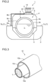
- Fig. 3 is a cross-sectional perspective view of a structure of the hydrogen pipe 10.
- the hydrogen pipe 10 is a multi-layered pipe including: an inner pipe 10a that allows the liquefied hydrogen L to flow therethrough; an outer pipe 10b that is arranged concentrically with the inner pipe 10a outside the inner pipe 10a; and a vacuumed layer 10c defined between the inner pipe 10a and the outer pipe 10b for heat insulation.
- the vacuumed layer 10c is an enclosed space communicable with a suction device 12 via a suction port 11 illustrated in Figs. 1 and 2 .
- a detector 13 that detects a vacuum degree of the vacuumed layer 10c is connected to the suction device 12.
- the vacuum degree of the vacuumed layer 10c detected by the detector 13 indicates an index value concerning a tendency that liquefied air resulting from nitrogen or oxygen condensed in air comes into existence on a surface of the outer pipe 10b.
- the detector 13 may detect a surface temperature of the hydrogen pipe 10, specifically, detect a surface temperature of the outer pipe 10b in place of detecting the vacuum degree of the vacuumed layer 10c.
- the surface temperature of the outer pipe 10b indicates an index value concerning a tendency that the liquefied air comes into existence on the surface of the outer pipe 10b in the same manner as the vacuum degree of the vacuumed layer 10c.
- At least the inner pipe 10a in the hydrogen pipe 10 is made of low-temperature steel having a property less likely to trigger embrittlement even under a cryogenic condition.
- the outer pipe 10b is made of low-temperature steel.
- the material of the outer pipe 10b is not necessarily limited to the low-temperature steel, and various kinds of metals and resins are adoptable.
- Fig. 4 is a side view of the cryogenic liquid pipe structure according to the embodiment of this disclosure
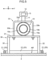
- Fig. 5 is a cross-sectional view of the cryogenic liquid pipe structure.
- the cross-sectional view of Fig. 5 omits illustration of the liquefied hydrogen (see Fig. 3 ) inside the inner pipe 10a
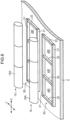
- Fig. 6 is a perspective view of a storage area AR defined on the top surface of the tank cover 4 by a storage area partitioning member 20.
- a direction parallel to a central axis of the hydrogen pipe 10 is referred to as a pipe axial direction X
- a direction perpendicularly intersecting the pipe axial direction X and an up-down direction (vertical direction) is referred to as a pipe axis-perpendicular direction Y.
- the cryogenic liquid pipe structure is a pipe structure for use in the vessel 1 that stores and carries the liquefied hydrogen L being a cryogenic liquid, and the cryogenic liquid pipe structure includes the storage area partitioning member 20 and support members 30 in addition to the hydrogen pipe 10.
- the hydrogen pipe 10 has a structure including unit pipes 10A each having a predetermined length and connected to each other in the pipe axial direction X.
- the unit pipes 10A are respectively connected to corresponding suction devices 12 for evacuation and maintaining of a vacuumed state in the vacuumed layer 10c via corresponding suction ports 11. That is to say, vacuuming by each suction device 12 for the vacuumed layer 10c in the hydrogen pipe 10 is not executed over an entire length of the hydrogen pipe 10, but is executed individually for each unit pipe 10A. This enables the vacuumed layer 10c in the hydrogen pipe 10 to rapidly have a predetermined vacuum degree.
- each detector 13 is connected to the respective suction devices 12. That is to say, each detector 13 individually detects the vacuum degree of the vacuumed layer 10c for each of the unit pipes 10A.
- the support members 30 are arranged in the pipe axial direction X on the top surface of the tank cover 4. Each of the support members 30 is in contact with the hydrogen pipe 10 and supports the hydrogen pipe 10 above and away from the tank cover 4. Each of the support members 30 has a base 31, a pair of legs 32, and a fastener 33.
- the base 31 is a plate-shaped member extending in the pipe axis-perpendicular direction Y just under the hydrogen pipe 10.
- the hydrogen pipe 10 is fixed to a top surface of the base 31 by the fastener 33.
- the base 31 is in contact with a lower surface of the hydrogen pipe 10 and directly supports the hydrogen pipe 10.
- the base 31 is in contact with a lower surface of the outer pipe 10b and supports the outer pipe 10b.
- the fastener 33 is a fastening member having an inverted U-shape in a front view.
- the fastener 33 is a U-bolt.
- the fastener 33 has an upper part 33a extending in the pipe axis-perpendicular direction Y, and a pair of side parts 33b extending downward from the opposite ends of the upper part 33a.
- the two side parts 33b are fastened from above to the base 31 respectively at left and right positions of the hydrogen pipe 10.
- the upper part 33a and the base 31 sandwich the hydrogen pipe 10 therebetween to fix the hydrogen pipe 10 to the support member 30.
- a lubricating member or a low frictional member may be arranged between the outer pipe 10b and the base 31 to permit the outer pipe 10b and the base 31 to shift relative to each other due to, for example, thermal contraction.
- the two legs 32 respectively extend downward from right and left ends of the base 31, that is, from the opposite ends of the base 31 in the pipe axis-perpendicular direction Y.
- Each of the legs 32 has a lower end fixed to the top surface of the tank cover 4.
- the support member 30 is made of low-temperature steel having a property less likely to trigger embrittlement even under a cryogenic condition.
- each of the components constituting the support member 30, i.e., the base 31, the legs 32, and the fastener 33 can be made of austenite stainless steel which is a kind of low-temperature steel.
- the austenite stainless steel particularly include low carbon stainless steel defined in the JIS standard, such as SUS304L and SUS316L. It is a matter of course that aluminum alloy or other material being low-temperature steel is adoptable in place of the austenite stainless steel.
- the storage area partitioning member 20 lies on the top surface of the tank cover 4 in such a manner as to protrude upward from the top surface of the tank cover 4.
- the storage area partitioning member 20 defines, on the top surface of the tank cover 4, a storage area AR for storing an evaporation accelerating fluid.
- the storage area AR defined on the top surface of the tank cover 4 is located blow the hydrogen pipe 10.
- the evaporation accelerating fluid stored in the storage area AR receives and evaporates a drop of liquefied air from the surface of the outer pipe 10b, the liquefied air coming into existence on the surface in accordance with a decrease in the temperature of the outer pipe 10b of the hydrogen pipe 10.
- the evaporation accelerating fluid may be any kind of material which turns into a liquid state at a normal temperature without a chemical reaction with the drop of liquefied air from the hydrogen pipe 10.
- Examples of the evaporation accelerating fluid include water, such as fresh water, water containing incidental impurities, and salt water.
- "seawater” belonging to salt water is used as the evaporation accelerating fluid.
- the storage area partitioning member 20 has an assembly of lengthwise frame members 21 each extending in the pipe axial direction X and crosswise frame members 22 connecting the lengthwise frame members 21 to each other in the pipe axis-perpendicular direction Y in combination.
- Each of the lengthwise frame members 21 defines an area end of the storage area AR in the pipe axis-perpendicular direction Y on the top surface of the tank cover 4, and each of the crosswise frame members 22 defines an area end of the storage area AR in the pipe axial direction X.
- Each of the lengthwise frame members 21 and the crosswise frame members 22 has an enough thickness with a value of, for example, tens of millimeters to hundreds of millimeters to allow the seawater serving as the evaporation accelerating fluid to be stored in the storage area AR.
- Each of the lengthwise frame member 21 and the crosswise frame members 22 can be made of austenite stainless steel which is a kind of low-temperature steel.
- Each of the lengthwise frame members 21 and the crosswise frame members 22 may be made of general structural soft steel in the same manner as the tank cover 4.
- Each of the lengthwise frame members 21 and the crosswise frame members 22 is fixedly attached to the top surface of the tank cover 4 by welding or other way.
- the storage area partitioning member 20 defines, on the top surface of the tank cover 4, a plurality of storage areas AR along the pipe axial direction X of the hydrogen pipe 10.
- the storage area partitioning member 20 defines the storage areas AR on the top surface of the tank cover 4 so that each of the storage areas AR lies below the corresponding unit pipe 10A constituting the hydrogen pipe 10.
- the vessel 1 includes a supply device 8 for the evaporation accelerating fluid, and a controller 9.
- the supply device 8 for the evaporation accelerating fluid is arranged in the vessel body 2.
- the supply device 8 for the evaporation accelerating fluid supplies the evaporation accelerating fluid to each storage area AR.
- the supply device 8 for the evaporation accelerating fluid is a seawater supply device 8.
- the seawater supply device 8 is a device that supplies seawater to each storage area AR defined on the top surface of the tank cover 4 by the storage area partitioning member 20.
- the seawater supply device 8 draws up the seawater from outside of the vessel body 2, and supplies the drawn-up seawater to each storage area AR.
- the seawater supply device 8 desirably supplies the seawater to each storage area AR so that a water level of the seawater to be stored in each storage area AR reaches a level substantially equivalent to the thickness of each of the lengthwise frame member 21 and the crosswise frame members 22, or slightly falls below the level.
- a seawater flow main pipe 8a and seawater flow auxiliary pipes 8b are provided between the seawater supply device 8 and each storage area AR, each of the pipes 8a, 8b serving as a pipe that allows the seawater to flow therethrough.
- the seawater flow main pipe 8a extends from the seawater supply device 8 to the side deck 7b and is arranged on the side deck 7b.
- Each of the seawater flow auxiliary pipes 8b branches from the seawater flow main pipe 8a to extend to the corresponding storage area AR located below the corresponding unit pipe 10A.
- the seawater flow auxiliary pipes 8b are respectively provided with valves 8c.
- the seawater supply device 8 can supply the seawater to each storage area AR individually in accordance with independent opening and closing of each of the valves 8c.
- the controller 9 includes a CPU (Central Processing Unit), a ROM (Read Only Memory) which stores a control program, and a RAM (Random Access Memory) for use as a work area of the CPU.
- the controller 9 controls the seawater supply device 8 and the valves 8c in response to execution of the control program stored in the ROM by the CPU.
- Each of the detectors 13 is electrically connected to the controller 9. With this configuration, information about the vacuum degree of the vacuumed layer 10c detected by each detector 13 for each of the unit pipes 10A is input to the controller 9.
- the controller 9 controls the seawater supply device 8 and each valve 8c to allow the seawater to be stored in each storage area AR when the vacuum degree of the vacuumed layer 10c detected by each detector 13 for each of the unit pipes 10A is out of a predetermined permissible range.
- the tendency that the liquefied air comes into existence on the surface of the hydrogen pipe 10 increases when the vacuum degree of the vacuumed layer 10c detected by each detector 13 is out of the predetermined permissible range.
- the controller 9 in this case controls the seawater supply device 8 and each valve 8c to supply the seawater to each storage area AR defined on the top surface of the tank cover 4.
- the storage area partitioning member 20 defines, on the top surface of the tank cover 4, the storage area AR for storing seawater serving as the evaporation accelerating fluid, and the hydrogen pipe 10 is supported via the support member 30 made of low-temperature steel.
- This configuration is advantageous to suppression of embrittlement of the tank cover 4 attributed to a drop of liquefied air from the surface of the hydrogen pipe 10, the liquefied air coming into existence on the surface in accordance with a decrease in the temperature of the hydrogen pipe 10.
- the hydrogen pipe 10 has a double structure including the inner pipe 10a, the outer pipe 10b, and the vacuumed layer 10c defined between the inner and outer pipes 10a, 10b.
- the temperature of the outer pipe 10b is maintained at a sufficiently higher value than a value of the temperature of the inner pipe 10a even when the liquefied hydrogen L flows into the inner pipe 10a as long as the vacuum degree of the vacuumed layer 10c is satisfactory.
- the vacuum degree of the vacuumed layer 10c may decrease because of long running of the vessel 1. An occurrence of such a decrease in the vacuum degree induces heat transfer between the inner pipe 10a and the outer pipe 10b, and thus reduces a temperature difference between the outer pipe 10b and the inner pipe 10a.
- the temperature of the outer pipe 10b may decrease to a value around -253°C or lower being the temperature of the liquefied hydrogen in the inner pipe 10a.
- the hydrogen pipe 10 has the structure including the unit pipes 10A connected to each other, and the vacuum degree of the vacuumed layer 10c is maintained individually for each of the unit pipes 10A as described above.
- the vacuum degree does not uniformly decrease over the entire length of the hydrogen pipe 10, and a decrease rate of the vacuum degree may vary depending on each unit pipe 10A. It is seen from this perspective that an occurrence of a decrease in the temperature of the outer pipe 10b to a value around the temperature of the liquefied hydrogen L is normally limited to one unit pipe 10A, or two or more unit pipes 10A, that is, a certain portion of the hydrogen pipe 10.
- a portion as a portion of the hydrogen pipe 10 having a surface temperature decreased to a value around the temperature of the liquefied hydrogen L is particularly referred to as "temperature decreasing portion".
- a vacuum degree of the vacuumed layer 10c detected by a specific detector 13 provided for a specific pipe unit pipe 10A corresponding to the temperature decreasing portion is out of the permissible range, the specific detector 13 being one of the detectors 13 arranged respectively for the unit pipes 10A.
- a crew of the vessel 1 repairs the specific unit pipe 10A corresponding to the temperature decreasing portion, or replaces the unit pipe with a new unit pipe 10A.
- nitrogen or oxygen contained in air may be condensed and liquefied air may come into existence on the surface of the outer pipe 10b at the temperature decreasing portion of the hydrogen pipe 10 before completion of these operations.
- a drop of the liquefied air then flows on the surface of the outer pipe 10b and falls down to the tank cover 4 located below the temperature decreasing portion, and the tank cover 4 is notably cooled by the liquefied air.
- the tank cover 4 is normally made of general structural soft steel, and thus may trigger low-temperature embrittlement attributed to the temperature decrease when cooled by the liquefied air.
- the storage area partitioning member 20 defines, on the top surface of the tank cover 4, each storage area AR for storing seawater in consideration of this problem.
- the controller 9 controls, on the basis of a result of the detection from each detector 13, the seawater supply device 8 and each valve 8c to allow the seawater to be stored in each storage area AR defined on the tank cover 4.
- the seawater stored in each storage area AR can reliably receive and rapidly evaporate a drop of the liquefied air from the hydrogen pipe 10. This keeps the liquefied air from reaching the tank cover 4 and notably cooling the tank cover 4, and thus results in achieving appropriate protection of the tank cover 4 from low-temperature embrittlement.
- the seawater serving as the evaporation accelerating fluid to be stored in each storage area AR is easily acquirable for the vessel 1 sailing on the sea, and can rapidly evaporate the drop of the liquefied air.
- the storage area partitioning member 20 defines, on the top surface of the tank cover 4, the storage areas AR along the pipe axial direction X of the hydrogen pipe 10. Specifically, the storage area partitioning member 20 defines, on the top surface of the tank cover 4, the storage areas AR so that each of the storage areas AR lies below the corresponding unit pipe 10A constituting the hydrogen pipe 10. Presumed here is an example case where the temperature drastically decreases in a specific unit pipe 10A among the unit pipes 10A, that is, the temperature drastically decreases in a portion of the hydrogen pipe 10 in the pipe axial direction X, and liquefied air comes into existence in the temperature decreasing portion where the drastic decrease in the temperature occurs.
- the vacuum degree of the vacuumed layer 10c detected by a specific detector 13 arranged for the specific unit pipe 10A corresponding to the temperature decreasing portion is out of the permissible range.
- the controller 9 controls, on the basis of a result of the detection from the specific detector 13, a specific valve 8c provided to a specific seawater flow auxiliary pipe 8b for the specific unit pipe 10A corresponding to the temperature decreasing portion to open, and remaining valves 8c to close, and further controls the seawater supply device 8.
- the seawater stored in the specific storage area AR defined on the top surface of the tank cover 4 can reliably receive and evaporate a drop of the liquefied air from the temperature decreasing portion being a portion of the hydrogen pipe 10. This consequently achieves appropriate protection of the tank cover 4 from low-temperature embrittlement.
- the temperature of the outer pipe 10b decreases to a value around the temperature of the liquefied hydrogen L.
- the support member 30 would be notably cooled through thermal conduction with the temperature decreasing portion.
- the base 31 and the fastener 33 of the support member 30, each being in contact with the hydrogen pipe 10 are notably cooled.
- the support member 30 is made of general structural soft steel in the same manner as the tank cover 4, the support member 30 would be likely to embrittle due to low-temperature embrittlement and fail to reliably support the hydrogen pipe 10.
- the embodiment adopts low-temperature steel having a property less likely to trigger embrittlement even under a cryogenic condition for the support member 30. This configuration hence attains satisfactory suppression of low-temperature embrittlement of the support member 30 even when the support member 30 is notably cooled, and enables the support member 30 to favorably maintain enough strength to support the hydrogen pipe 10.
- cryogenic liquid pipe structure and the vessel according to the embodiment of this disclosure are described, the disclosure is not limited thereto and may adopt the following modified embodiments.
- a configuration of the storage area partitioning member 20 that defines, on the top surface of the tank cover 4, a plurality of storage areas AR along the pipe axial direction X of the hydrogen pipe 10.
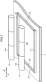
- a storage area partitioning member 20 having a configuration illustrated in Fig. 7 may be adopted.
- Fig. 7 shows a modified storage area partitioning member 20 that defines, on a top surface of a tank cover 4, a single storage area AR to solely extend over an entire region which a hydrogen pipe 10 occupies.
- This arrangement allows the seawater stored in the single storage area AR defined on the tank cover 4 to reliably receive and evaporate a drop of liquefied air from each temperature decreasing portion even when the pipe arrangement is complicated resulting from the hydrogen pipe 10 extending while appropriately curving above the tank cover 4 or the temperature drastically decreases in many portions of the hydrogen pipe 10.
- the storage area partitioning member 20 may be provided to define the storage area AR limitedly below a specific portion of the hydrogen pipe 10 where a vacuum degree of the vacuumed layer 10c is estimated in advance to particularly easily decrease.
- the embodiment exemplifies the structure where the storage area partitioning member 20 has a frame shape defined by the lengthwise frame members 21 and the crosswise frame members 22, the disclosure is not limited to this configuration.
- the storage area partitioning member 20 may be in the form of a box container opening upward.
- the storage area partitioning member 20 in the form of the container is called "storage area partitioning container” hereafter.
- the storage area partitioning container has peripheral walls corresponding to the lengthwise frame members 21 and the crosswise frame members 22, and a bottom wall connected to lower ends of the peripheral walls.
- the storage area partitioning container defines, as a storage area AR, an area surrounded by the peripheral walls and the bottom wall in a state where the bottom wall is in contact with the top surface of the tank cover 4.
- the storage area partitioning container can receive even a drop of liquefied air falling from the hydrogen pipe 10 before storage of the seawater by the bottom wall, and evaporate the drop of the liquefied air. This prevents the drop of the liquefied air, which has fallen from the hydrogen pipe 10 before storage of the seawater in the storage area AR, from reaching the tank cover 4, and thus results in achieving appropriate protection of the tank cover 4 from low-temperature embrittlement.
- the storage area partitioning container is further desirably made of low-temperature steel, such as austenite stainless steel. This configuration attains suppression of low-temperature embrittlement of the storage area partitioning container attributed to the drop of the liquefied air from the hydrogen pipe 10 onto the bottom wall of the storage area partitioning container.
- the vessel body 2 may include a water tank for storing rainwater so as to supply the water from the water tank to each storage area AR.
- the embodiment exemplifies the structure where the hydrogen pipe 10 is arranged above the tank cover 4 in the vessel 1
- the hydrogen pipe 10 may be arranged above the deck 7 or may be arranged in a cargo hold chamber, as well as above the tank cover 4.
- the storage area partitioning member 20 is providable in the place other than the place above the tank cover 4 with application of the support structure by the support member 30 in the same manner as the embodiment.
- a pipe in a no-double structure without a vacuumed layer is adoptable as the low-temperature pipe.
- a pipe including: a main pipe made of low-temperature steel; and a heat insulative layer, such as a urethane layer, on an outer surface of the main pipe is adoptable as the low-temperature pipe.
- the described embodiment exemplifies application of the pipe structure in the disclosure to the vessel 1 that stores and carries the liquefied hydrogen L having the boiling point of -253°C under a normal pressure, but the disclosure is not limited thereto.
- the pipe structure in the disclosure is applicable to any vessel that stores a cryogenic liquid having a boiling point of -196°C or lower under a normal pressure, and thus various kinds of vessel can adopt the pipe structure in this disclosure to that extent.
- the pipe structure in the disclosure is applicable to a vessel that stores liquefied helium having a boiling point of -269°C under a normal pressure or liquefied nitrogen having a boiling point of -196°C under the normal pressure.
- a cryogenic liquid pipe structure is for use in a vessel that stores a cryogenic liquid having a boiling point of -196°C or lower under a normal pressure.
- the cryogenic liquid pipe structure includes: a low-temperature pipe arranged above and away from a structural member of the vessel and extending along the structural member for allowing the cryogenic liquid to flow therethrough; and a storage area partitioning member that lies on the structural member, and defines, on the structural member, a storage area for storing an evaporation accelerating fluid to receive and evaporate a drop of liquefied air from a surface of the low-temperature pipe.
- the low-temperature pipe that allows the cryogenic liquid having the boiling point of -196°C or lower under the normal pressure to flow therethrough has a possibility that a surface temperature of at least a portion of the pipe decreases to a value around the temperature of the cryogenic liquid.
- Nitrogen or oxygen in air may be condensed and liquefied air may come into existence on a surface of the temperature decreasing portion of the low-temperature pipe where the temperature drastically decreases.
- a drop of the liquefied air flows on the surface of the low-temperature pipe and falls down to the structural member of the vessel located below the low-temperature pipe, and the structural member is notably cooled by the liquefied air.
- the structural member of the vessel is normally made of general structural soft steel, and thus may trigger low-temperature embrittlement attributed to the temperature decrease when cooled by the liquefied air.
- the storage area partitioning member defines, on the top surface of the structural member, the storage area for storing the evaporation accelerating fluid in consideration of the problem. In the state where the evaporation accelerating fluid is stored in the storage area on the structural member, the evaporation accelerating fluid can reliably receive and evaporate the drop of the liquefied air from the low-temperature pipe. This configuration prevents the liquefied air from reaching the structural member of the vessel with a sufficiently high probability, and achieves appropriate protection of the structural member from low-temperature embrittlement.
- the evaporation accelerating fluid may include seawater.
- the seawater is easily acquirable for the vessel sailing on the sea, and can rapidly evaporate the drop of the liquefied air.
- the storage area partitioning member may define, on the structural member, a plurality of the storage areas along a pipe axial direction of the low-temperature pipe.
- a specific storage area corresponding to the temperature decreasing portion among the storage areas defined on the structural member may store the evaporation accelerating fluid.
- the evaporation accelerating fluid stored in the specific storage area defined on the structural member can reliably receive and evaporate the drop of the liquefied air from the temperature decreasing portion being a portion of the low-temperature pipe. This consequently achieves appropriate protection of the structural member from low-temperature embrittlement.
- the storage area partitioning member may define, on the structural member, the storage area to solely extend over an entire region which the low-temperature pipe occupies.
- the evaporation accelerating fluid stored in a single storage area defined on the structural member can reliably receive and evaporate a drop of liquefied air from each temperature decreasing portion even when the pipe arrangement is complicated resulting from the low-temperature pipe extending while appropriately curving above the structural member or the temperature drastically decreases in many portions of the low-temperature pipe.
- the cryogenic liquid pipe structure may further include a support member that is in contact with the low-temperature pipe and supports the low-temperature pipe above and away from the structural member.
- the support member may be made of low-temperature steel which is less likely to trigger low-temperature embrittlement than the structural member.
- the support member that supports the low-temperature pipe is notably cooled through thermal conduction with the low-temperature pipe.
- the support member is made of the same material as that of the structural member of the vessel, the support member would be likely to embrittle due to the low-temperature embrittlement and may fail to reliably support the low-temperature pipe.
- the support member is made of low-temperature steel having a property less likely to trigger low-temperature embrittlement than the property of the structural member. This configuration hence attains satisfactory suppression of low-temperature embrittlement of the support member even when the support member is notably cooled, and enables the support member to favorably maintain enough strength to support the low-temperature pipe.
- a vessel according to another aspect of the disclosure stores a cryogenic liquid having a boiling point of -196°C or lower under a normal pressure.
- the vessel includes: a vessel body having a predetermined structural member; the above-described cryogenic liquid pipe structure; and a supply device that supplies the evaporation accelerating fluid to the storage area defined on the structural member by the storage area partitioning member.
- the vessel permits the supply device to supply the evaporation accelerating fluid therefrom to the storage area defined on the structural member for liquefied air coming into existence on the surface of the surface of the low-temperature pipe.
- the configuration enables the evaporation accelerating fluid stored in the storage area on the structural member to reliably receive and evaporate the drop of the liquefied air from the low-temperature pipe. This achieves protection of the structural member constituting the vessel body from low-temperature embrittlement.
- the vessel may further include: a detector that detects an index value concerning a tendency that the liquefied air comes into existence on the surface of the low-temperature pipe; and a controller that controls the supply device so as to allow the evaporation accelerating fluid to be stored in the storage area when the index value detected by the detector is out of a predetermined permissible range.
- the controller in this case controls the supply device to supply the evaporation accelerating fluid to the storage area defined on the structural member.
- the configuration enables the evaporation accelerating fluid stored in the storage area on the structural member to reliably receive and evaporate the drop of the liquefied air from the low-temperature pipe.
Landscapes
- Engineering & Computer Science (AREA)
- Mechanical Engineering (AREA)
- Chemical & Material Sciences (AREA)
- Combustion & Propulsion (AREA)
- Ocean & Marine Engineering (AREA)
- General Engineering & Computer Science (AREA)
- Filling Or Discharging Of Gas Storage Vessels (AREA)
- Pipeline Systems (AREA)
Abstract
Description
- The present disclosure relates to a cryogenic liquid pipe structure for use in a vessel that stores a cryogenic liquid having a boiling point of -196°C or lower under a normal pressure, and relates to a vessel.
-
Patent Literature 1 below has been known as describing a pipe for allowing such a cryogenic liquid as described above to flow therethrough. Specifically, the pipe inPatent Literature 1 has a double structure, i.e., is a double pipe, for allowing liquefied hydrogen having a boiling point of -253°C under a normal pressure to flow therethrough, and the pipe includes an inner pipe and an outer pipe concentrically arranged. The inner pipe and the outer pipe define therebetween a vacuumed layer for blocking heat transfer. Heat insulation by the vacuumed layer maintains the liquefied hydrogen in the inner pipe at a temperature equal to or lower than the boiling point thereof. - A decrease in a vacuum degree of the heat insulative layer in the double pipe for liquefied hydrogen in
Patent Literature 1 causes heat transfer between the inner pipe and the outer pipe, resulting in a smaller difference between a temperature of the outer pipe and a temperature of the inner pipe. When the temperature of the outer pipe decreases to reach a value around the temperature of the liquefied hydrogen in the inner pipe, air is likely to be condensed on the surface of the outer pipe. - Liquefied air containing liquefied nitrogen or liquefied oxygen may come into existence on the surface of the outer pipe, and, in such a case, a drop of the liquefied air flows on the surface of the outer pipe and falls down to a structural member located below the double pipe and constituting a vessel body of a vessel. In this case, the structural member is notably cooled by the liquefied air. The structural member is normally made of general structural soft steel, and thus has a possibility of triggering low-temperature embrittlement attributed to the decrease in the temperature when cooled by the liquefied air.
- Patent Literature 1:
Japanese Unexamined Patent Publication No. 2017-20914 - This disclosure has been achieved in consideration of the circumstances described above, and an object of the disclosure is to provide a cryogenic liquid pipe structure that enables suppression of embrittlement of a structural member of a vessel attributed to a drop of liquefied air from a surface of a pipe for allowing a cryogenic liquid to flow therethrough, the liquefied air coming into existence on the surface in accordance with a decrease in a temperature of the pipe, and to provide a vessel.
- A cryogenic liquid pipe structure according to one aspect of the present disclosure is for use in a vessel that stores a cryogenic liquid having a boiling point of -196°C or lower under a normal pressure. The cryogenic liquid pipe structure includes: a low-temperature pipe arranged above and away from a structural member of the vessel and extending along the structural member for allowing the cryogenic liquid to flow therethrough; and a storage area partitioning member that lies on the structural member, and defines, on the structural member, a storage area for storing an evaporation accelerating fluid to receive and evaporate a drop of liquefied air from a surface of the low-temperature pipe.
- A vessel according to another aspect of the disclosure stores a cryogenic liquid having a boiling point of -196°C or lower under a normal pressure. The vessel includes: a vessel body having a predetermined structural member; the above-described cryogenic liquid pipe structure; and a supply device that supplies the evaporation accelerating fluid to the storage area defined on the structural member by the storage area partitioning member.
-
-
Fig. 1 is a side view of a schematic structure of a vessel adopting a cryogenic liquid pipe structure according to an embodiment of this disclosure. -
Fig. 2 is a cross-sectional view taken along the line II-II inFig. 1 . -
Fig. 3 is a cross-sectional perspective view of a structure of a hydrogen pipe. -
Fig. 4 is a side view of the cryogenic liquid pipe structure. -
Fig. 5 is a cross-sectional view taken along the line V-V inFig. 4 . -
Fig. 6 is a perspective view of a storage area defined on a top surface of a tank cover by a storage area partitioning member. -
Fig. 7 is a perspective view of a modified storage area defined on a top surface of a tank cover by a storage area partitioning member. - Hereinafter, a cryogenic liquid pipe structure and a vessel that stores and carries a cryogenic liquid according to an embodiment of this disclosure will be described with reference to the accompanying drawings.
-
Fig. 1 is a side view of a schematic structure of a vessel adopting a cryogenic liquid pipe structure according to an embodiment of this disclosure, andFig. 2 is a cross-sectional view of the schematic structure of the vessel. Avessel 1 illustrated in the drawings is a liquefied hydrogen carrier that stores and carries liquefied hydrogen L (Fig. 2 ), and the vessel includes avessel body 2 andtanks 3 mounted in thevessel body 2. The liquefied hydrogen L to be stored and carried by thevessel 1 indicates hydrogen in a liquid state cooled to a temperature equal to or lower than a boiling point of -253°C under a normal pressure, and corresponds to an example of the cryogenic liquid in this disclosure. - The
vessel body 2 includes cargo holds 5 opening upward in its regions respectively for thetanks 3. Abulkhead 6 is located between adjacent cargo holds 5 to separate the cargo holds 5 from each other. - The
vessel body 2 further includes adeck 7 surrounding the cargo holds 5. Thedeck 7 has aforecastle 7a located in front of the cargo holds 5, a pair ofside decks stern deck 7d located in the rear of the cargo holds 5. Thevessel body 2 is made of steel material except for low-temperature steel. For instance, each of thedeck members 7a to 7d is made of general structural soft steel. Although a kind of the structural soft steel is not particularly limited, an SS member (rolled steel member for general structure) defined in the JIS standard is adoptable as an example. - Each of the
tanks 3 has a long cylindrical shape extending in a vessel longitudinal direction of thevessel 1, and eachtank 3 is accommodated in thecorresponding cargo hold 5. Thetank 3 has aninner tank 3a for storing the liquefied hydrogen L inside and anouter tank 3b arranged concentrically with theinner tank 3a outside theinner tank 3a. Theinner tank 3a and theouter tank 3b define therebetween a vacuumedlayer 3c for heat insulation. The vacuumedlayer 3c is an enclosed space communicable with an unillustrated suction device. -
Tank covers 4 are arranged over thetanks 3 respectively. Eachtank cover 4 constitutes a part of thevessel body 2, and defines an accommodation space S for eachtank 3 in cooperation with thecorresponding cargo hold 5. Thetank cover 4 is made of steel material except for low-temperature steel in the same manner as thevessel body 2. For instance, thetank cover 4 is made of general structural soft steel, such as the aforementioned SS member. In other words, thetank cover 4 is made of steel material which is more likely to trigger low-temperature embrittlement than low-temperature steel under a cryogenic condition. - The
tank cover 4 has a top surface above which ahydrogen pipe 10 is arranged. Thehydrogen pipe 10 is used to at least unload the liquefied hydrogen L in thetank 3 from thevessel 1 and allows the liquefied hydrogen L to flow therethrough. Thehydrogen pipe 10 is arranged above and away from the top surface of thetank cover 4 and extends along the top surface of thetank cover 4 while appropriately curving. Thehydrogen pipe 10 corresponds to an example of the "low-temperature pipe" in the disclosure. Thetank cover 4 located below thehydrogen pipe 10 corresponds to an example of the structural member of the vessel in the disclosure. -
Fig. 3 is a cross-sectional perspective view of a structure of thehydrogen pipe 10. As illustrated in the drawing, thehydrogen pipe 10 is a multi-layered pipe including: aninner pipe 10a that allows the liquefied hydrogen L to flow therethrough; anouter pipe 10b that is arranged concentrically with theinner pipe 10a outside theinner pipe 10a; and avacuumed layer 10c defined between theinner pipe 10a and theouter pipe 10b for heat insulation. The vacuumedlayer 10c is an enclosed space communicable with asuction device 12 via asuction port 11 illustrated inFigs. 1 and2 . As illustrated inFig. 1 , adetector 13 that detects a vacuum degree of the vacuumedlayer 10c is connected to thesuction device 12. Although details will be described later, the vacuum degree of the vacuumedlayer 10c detected by thedetector 13 indicates an index value concerning a tendency that liquefied air resulting from nitrogen or oxygen condensed in air comes into existence on a surface of theouter pipe 10b. Thedetector 13 may detect a surface temperature of thehydrogen pipe 10, specifically, detect a surface temperature of theouter pipe 10b in place of detecting the vacuum degree of the vacuumedlayer 10c. The surface temperature of theouter pipe 10b indicates an index value concerning a tendency that the liquefied air comes into existence on the surface of theouter pipe 10b in the same manner as the vacuum degree of thevacuumed layer 10c. - In the embodiment, at least the
inner pipe 10a in thehydrogen pipe 10 is made of low-temperature steel having a property less likely to trigger embrittlement even under a cryogenic condition. - In the embodiment, the
outer pipe 10b is made of low-temperature steel. The material of theouter pipe 10b is not necessarily limited to the low-temperature steel, and various kinds of metals and resins are adoptable. -
Fig. 4 is a side view of the cryogenic liquid pipe structure according to the embodiment of this disclosure, andFig. 5 is a cross-sectional view of the cryogenic liquid pipe structure. The cross-sectional view ofFig. 5 omits illustration of the liquefied hydrogen (seeFig. 3 ) inside theinner pipe 10a.Fig. 6 is a perspective view of a storage area AR defined on the top surface of thetank cover 4 by a storagearea partitioning member 20. In the description below, a direction parallel to a central axis of thehydrogen pipe 10 is referred to as a pipe axial direction X, and a direction perpendicularly intersecting the pipe axial direction X and an up-down direction (vertical direction) is referred to as a pipe axis-perpendicular direction Y. - The cryogenic liquid pipe structure is a pipe structure for use in the
vessel 1 that stores and carries the liquefied hydrogen L being a cryogenic liquid, and the cryogenic liquid pipe structure includes the storagearea partitioning member 20 andsupport members 30 in addition to thehydrogen pipe 10. - As shown in
Fig. 4 , thehydrogen pipe 10 has a structure includingunit pipes 10A each having a predetermined length and connected to each other in the pipe axial direction X. In thehydrogen pipe 10, theunit pipes 10A are respectively connected tocorresponding suction devices 12 for evacuation and maintaining of a vacuumed state in the vacuumedlayer 10c via correspondingsuction ports 11. That is to say, vacuuming by eachsuction device 12 for the vacuumedlayer 10c in thehydrogen pipe 10 is not executed over an entire length of thehydrogen pipe 10, but is executed individually for eachunit pipe 10A. This enables the vacuumedlayer 10c in thehydrogen pipe 10 to rapidly have a predetermined vacuum degree. Further, in an occurrence of a decrease in the vacuum degree of the vacuumedlayer 10c, the occurrence can be limited to a specific portion of thehydrogen pipe 10 without progressing therefrom. Correspondingdetectors 13 are connected to therespective suction devices 12. That is to say, eachdetector 13 individually detects the vacuum degree of the vacuumedlayer 10c for each of theunit pipes 10A. - The
support members 30 are arranged in the pipe axial direction X on the top surface of thetank cover 4. Each of thesupport members 30 is in contact with thehydrogen pipe 10 and supports thehydrogen pipe 10 above and away from thetank cover 4. Each of thesupport members 30 has abase 31, a pair oflegs 32, and afastener 33. - The
base 31 is a plate-shaped member extending in the pipe axis-perpendicular direction Y just under thehydrogen pipe 10. Thehydrogen pipe 10 is fixed to a top surface of the base 31 by thefastener 33. In other words, thebase 31 is in contact with a lower surface of thehydrogen pipe 10 and directly supports thehydrogen pipe 10. Specifically, thebase 31 is in contact with a lower surface of theouter pipe 10b and supports theouter pipe 10b. - The
fastener 33 is a fastening member having an inverted U-shape in a front view. In the embodiment, thefastener 33 is a U-bolt. Specifically, thefastener 33 has anupper part 33a extending in the pipe axis-perpendicular direction Y, and a pair ofside parts 33b extending downward from the opposite ends of theupper part 33a. The twoside parts 33b are fastened from above to the base 31 respectively at left and right positions of thehydrogen pipe 10. In this manner, theupper part 33a and the base 31 sandwich thehydrogen pipe 10 therebetween to fix thehydrogen pipe 10 to thesupport member 30. A lubricating member or a low frictional member may be arranged between theouter pipe 10b and the base 31 to permit theouter pipe 10b and the base 31 to shift relative to each other due to, for example, thermal contraction. - The two
legs 32 respectively extend downward from right and left ends of thebase 31, that is, from the opposite ends of the base 31 in the pipe axis-perpendicular direction Y. Each of thelegs 32 has a lower end fixed to the top surface of thetank cover 4. - The
support member 30 is made of low-temperature steel having a property less likely to trigger embrittlement even under a cryogenic condition. For instance, each of the components constituting thesupport member 30, i.e., thebase 31, thelegs 32, and thefastener 33, can be made of austenite stainless steel which is a kind of low-temperature steel. Favorable examples of the austenite stainless steel particularly include low carbon stainless steel defined in the JIS standard, such as SUS304L and SUS316L. It is a matter of course that aluminum alloy or other material being low-temperature steel is adoptable in place of the austenite stainless steel. - The storage
area partitioning member 20 lies on the top surface of thetank cover 4 in such a manner as to protrude upward from the top surface of thetank cover 4. The storagearea partitioning member 20 defines, on the top surface of thetank cover 4, a storage area AR for storing an evaporation accelerating fluid. The storage area AR defined on the top surface of thetank cover 4 is located blow thehydrogen pipe 10. The evaporation accelerating fluid stored in the storage area AR receives and evaporates a drop of liquefied air from the surface of theouter pipe 10b, the liquefied air coming into existence on the surface in accordance with a decrease in the temperature of theouter pipe 10b of thehydrogen pipe 10. The evaporation accelerating fluid may be any kind of material which turns into a liquid state at a normal temperature without a chemical reaction with the drop of liquefied air from thehydrogen pipe 10. Examples of the evaporation accelerating fluid include water, such as fresh water, water containing incidental impurities, and salt water. In the embodiment, "seawater" belonging to salt water is used as the evaporation accelerating fluid. - The storage
area partitioning member 20 has an assembly oflengthwise frame members 21 each extending in the pipe axial direction X and crosswiseframe members 22 connecting thelengthwise frame members 21 to each other in the pipe axis-perpendicular direction Y in combination. Each of thelengthwise frame members 21 defines an area end of the storage area AR in the pipe axis-perpendicular direction Y on the top surface of thetank cover 4, and each of thecrosswise frame members 22 defines an area end of the storage area AR in the pipe axial direction X. Each of thelengthwise frame members 21 and thecrosswise frame members 22 has an enough thickness with a value of, for example, tens of millimeters to hundreds of millimeters to allow the seawater serving as the evaporation accelerating fluid to be stored in the storage area AR. Each of thelengthwise frame member 21 and thecrosswise frame members 22 can be made of austenite stainless steel which is a kind of low-temperature steel. Each of thelengthwise frame members 21 and thecrosswise frame members 22 may be made of general structural soft steel in the same manner as thetank cover 4. Each of thelengthwise frame members 21 and thecrosswise frame members 22 is fixedly attached to the top surface of thetank cover 4 by welding or other way. - In the embodiment, as illustrated in
Fig. 4 andFig. 6 , the storagearea partitioning member 20 defines, on the top surface of thetank cover 4, a plurality of storage areas AR along the pipe axial direction X of thehydrogen pipe 10. In this case, the storagearea partitioning member 20 defines the storage areas AR on the top surface of thetank cover 4 so that each of the storage areas AR lies below the correspondingunit pipe 10A constituting thehydrogen pipe 10. - As illustrated in
Fig. 1 , thevessel 1 includes asupply device 8 for the evaporation accelerating fluid, and acontroller 9. - The
supply device 8 for the evaporation accelerating fluid is arranged in thevessel body 2. Thesupply device 8 for the evaporation accelerating fluid supplies the evaporation accelerating fluid to each storage area AR. In the embodiment, thesupply device 8 for the evaporation accelerating fluid is aseawater supply device 8. Theseawater supply device 8 is a device that supplies seawater to each storage area AR defined on the top surface of thetank cover 4 by the storagearea partitioning member 20. Theseawater supply device 8 draws up the seawater from outside of thevessel body 2, and supplies the drawn-up seawater to each storage area AR. At this time, theseawater supply device 8 desirably supplies the seawater to each storage area AR so that a water level of the seawater to be stored in each storage area AR reaches a level substantially equivalent to the thickness of each of thelengthwise frame member 21 and thecrosswise frame members 22, or slightly falls below the level. - A seawater flow
main pipe 8a and seawater flowauxiliary pipes 8b are provided between theseawater supply device 8 and each storage area AR, each of thepipes main pipe 8a extends from theseawater supply device 8 to theside deck 7b and is arranged on theside deck 7b. Each of the seawater flowauxiliary pipes 8b branches from the seawater flowmain pipe 8a to extend to the corresponding storage area AR located below the correspondingunit pipe 10A. The seawater flowauxiliary pipes 8b are respectively provided withvalves 8c. Theseawater supply device 8 can supply the seawater to each storage area AR individually in accordance with independent opening and closing of each of thevalves 8c. - The
controller 9 includes a CPU (Central Processing Unit), a ROM (Read Only Memory) which stores a control program, and a RAM (Random Access Memory) for use as a work area of the CPU. Thecontroller 9 controls theseawater supply device 8 and thevalves 8c in response to execution of the control program stored in the ROM by the CPU. Each of thedetectors 13 is electrically connected to thecontroller 9. With this configuration, information about the vacuum degree of the vacuumedlayer 10c detected by eachdetector 13 for each of theunit pipes 10A is input to thecontroller 9. - The
controller 9 controls theseawater supply device 8 and eachvalve 8c to allow the seawater to be stored in each storage area AR when the vacuum degree of the vacuumedlayer 10c detected by eachdetector 13 for each of theunit pipes 10A is out of a predetermined permissible range. The tendency that the liquefied air comes into existence on the surface of thehydrogen pipe 10 increases when the vacuum degree of the vacuumedlayer 10c detected by eachdetector 13 is out of the predetermined permissible range. Thecontroller 9 in this case controls theseawater supply device 8 and eachvalve 8c to supply the seawater to each storage area AR defined on the top surface of thetank cover 4. - As described heretofore, in the embodiment, the storage
area partitioning member 20 defines, on the top surface of thetank cover 4, the storage area AR for storing seawater serving as the evaporation accelerating fluid, and thehydrogen pipe 10 is supported via thesupport member 30 made of low-temperature steel. This configuration is advantageous to suppression of embrittlement of thetank cover 4 attributed to a drop of liquefied air from the surface of thehydrogen pipe 10, the liquefied air coming into existence on the surface in accordance with a decrease in the temperature of thehydrogen pipe 10. - The
hydrogen pipe 10 has a double structure including theinner pipe 10a, theouter pipe 10b, and the vacuumedlayer 10c defined between the inner andouter pipes outer pipe 10b is maintained at a sufficiently higher value than a value of the temperature of theinner pipe 10a even when the liquefied hydrogen L flows into theinner pipe 10a as long as the vacuum degree of the vacuumedlayer 10c is satisfactory. However, the vacuum degree of the vacuumedlayer 10c may decrease because of long running of thevessel 1. An occurrence of such a decrease in the vacuum degree induces heat transfer between theinner pipe 10a and theouter pipe 10b, and thus reduces a temperature difference between theouter pipe 10b and theinner pipe 10a. In an extreme example, the temperature of theouter pipe 10b may decrease to a value around -253°C or lower being the temperature of the liquefied hydrogen in theinner pipe 10a. - It is noted here that the
hydrogen pipe 10 has the structure including theunit pipes 10A connected to each other, and the vacuum degree of the vacuumedlayer 10c is maintained individually for each of theunit pipes 10A as described above. In this configuration, the vacuum degree does not uniformly decrease over the entire length of thehydrogen pipe 10, and a decrease rate of the vacuum degree may vary depending on eachunit pipe 10A. It is seen from this perspective that an occurrence of a decrease in the temperature of theouter pipe 10b to a value around the temperature of the liquefied hydrogen L is normally limited to oneunit pipe 10A, or two ormore unit pipes 10A, that is, a certain portion of thehydrogen pipe 10. Under the circumstances, such a portion as a portion of thehydrogen pipe 10 having a surface temperature decreased to a value around the temperature of the liquefied hydrogen L is particularly referred to as "temperature decreasing portion". When thehydrogen pipe 10 has such a temperature decreasing portion, a vacuum degree of the vacuumedlayer 10c detected by aspecific detector 13 provided for a specificpipe unit pipe 10A corresponding to the temperature decreasing portion is out of the permissible range, thespecific detector 13 being one of thedetectors 13 arranged respectively for theunit pipes 10A. - When the
hydrogen pipe 10 has the temperature decreasing portion, a crew of thevessel 1 repairs thespecific unit pipe 10A corresponding to the temperature decreasing portion, or replaces the unit pipe with anew unit pipe 10A. However, nitrogen or oxygen contained in air may be condensed and liquefied air may come into existence on the surface of theouter pipe 10b at the temperature decreasing portion of thehydrogen pipe 10 before completion of these operations. A drop of the liquefied air then flows on the surface of theouter pipe 10b and falls down to thetank cover 4 located below the temperature decreasing portion, and thetank cover 4 is notably cooled by the liquefied air. Thetank cover 4 is normally made of general structural soft steel, and thus may trigger low-temperature embrittlement attributed to the temperature decrease when cooled by the liquefied air. - In the embodiment, the storage
area partitioning member 20 defines, on the top surface of thetank cover 4, each storage area AR for storing seawater in consideration of this problem. Thecontroller 9 controls, on the basis of a result of the detection from eachdetector 13, theseawater supply device 8 and eachvalve 8c to allow the seawater to be stored in each storage area AR defined on thetank cover 4. In this state, the seawater stored in each storage area AR can reliably receive and rapidly evaporate a drop of the liquefied air from thehydrogen pipe 10. This keeps the liquefied air from reaching thetank cover 4 and notably cooling thetank cover 4, and thus results in achieving appropriate protection of thetank cover 4 from low-temperature embrittlement. - In addition, the seawater serving as the evaporation accelerating fluid to be stored in each storage area AR is easily acquirable for the
vessel 1 sailing on the sea, and can rapidly evaporate the drop of the liquefied air. - In the embodiment, the storage
area partitioning member 20 defines, on the top surface of thetank cover 4, the storage areas AR along the pipe axial direction X of thehydrogen pipe 10. Specifically, the storagearea partitioning member 20 defines, on the top surface of thetank cover 4, the storage areas AR so that each of the storage areas AR lies below the correspondingunit pipe 10A constituting thehydrogen pipe 10. Presumed here is an example case where the temperature drastically decreases in aspecific unit pipe 10A among theunit pipes 10A, that is, the temperature drastically decreases in a portion of thehydrogen pipe 10 in the pipe axial direction X, and liquefied air comes into existence in the temperature decreasing portion where the drastic decrease in the temperature occurs. In this case, the vacuum degree of the vacuumedlayer 10c detected by aspecific detector 13 arranged for thespecific unit pipe 10A corresponding to the temperature decreasing portion is out of the permissible range. Thecontroller 9 controls, on the basis of a result of the detection from thespecific detector 13, aspecific valve 8c provided to a specific seawater flowauxiliary pipe 8b for thespecific unit pipe 10A corresponding to the temperature decreasing portion to open, and remainingvalves 8c to close, and further controls theseawater supply device 8. - The seawater drawn up through the action of the
seawater supply device 8 under the control by thecontroller 9 flows through the seawater flowmain pipe 8a and the specific seawater flowauxiliary pipe 8b. The seawater flowing through the specific seawater flowauxiliary pipe 8b flows into a specific storage area AR communicating with the specific seawater flowauxiliary pipe 8b to be stored therein, the specific storage area AR lying below thespecific unit pipe 10A corresponding to the temperature decreasing portion. In this manner, the seawater stored in the specific storage area AR defined on the top surface of thetank cover 4 can reliably receive and evaporate a drop of the liquefied air from the temperature decreasing portion being a portion of thehydrogen pipe 10. This consequently achieves appropriate protection of thetank cover 4 from low-temperature embrittlement. - In the temperature decreasing portion of the
hydrogen pipe 10, the temperature of theouter pipe 10b decreases to a value around the temperature of the liquefied hydrogen L. If the temperature decreasing portion is provided with thesupport member 30, thesupport member 30 would be notably cooled through thermal conduction with the temperature decreasing portion. In particular, thebase 31 and thefastener 33 of thesupport member 30, each being in contact with thehydrogen pipe 10, are notably cooled. If thesupport member 30 is made of general structural soft steel in the same manner as thetank cover 4, thesupport member 30 would be likely to embrittle due to low-temperature embrittlement and fail to reliably support thehydrogen pipe 10. Considering the foregoing, the embodiment adopts low-temperature steel having a property less likely to trigger embrittlement even under a cryogenic condition for thesupport member 30. This configuration hence attains satisfactory suppression of low-temperature embrittlement of thesupport member 30 even when thesupport member 30 is notably cooled, and enables thesupport member 30 to favorably maintain enough strength to support thehydrogen pipe 10. - Heretofore, although the cryogenic liquid pipe structure and the vessel according to the embodiment of this disclosure are described, the disclosure is not limited thereto and may adopt the following modified embodiments.
- In the embodiment, described is a configuration of the storage
area partitioning member 20 that defines, on the top surface of thetank cover 4, a plurality of storage areas AR along the pipe axial direction X of thehydrogen pipe 10. Alternatively, a storagearea partitioning member 20 having a configuration illustrated inFig. 7 may be adopted. Specifically,Fig. 7 shows a modified storagearea partitioning member 20 that defines, on a top surface of atank cover 4, a single storage area AR to solely extend over an entire region which ahydrogen pipe 10 occupies. This arrangement allows the seawater stored in the single storage area AR defined on thetank cover 4 to reliably receive and evaporate a drop of liquefied air from each temperature decreasing portion even when the pipe arrangement is complicated resulting from thehydrogen pipe 10 extending while appropriately curving above thetank cover 4 or the temperature drastically decreases in many portions of thehydrogen pipe 10. - Alternatively, the storage
area partitioning member 20 may be provided to define the storage area AR limitedly below a specific portion of thehydrogen pipe 10 where a vacuum degree of the vacuumedlayer 10c is estimated in advance to particularly easily decrease. - Although the embodiment exemplifies the structure where the storage
area partitioning member 20 has a frame shape defined by thelengthwise frame members 21 and thecrosswise frame members 22, the disclosure is not limited to this configuration. For instance, the storagearea partitioning member 20 may be in the form of a box container opening upward. The storagearea partitioning member 20 in the form of the container is called "storage area partitioning container" hereafter. The storage area partitioning container has peripheral walls corresponding to thelengthwise frame members 21 and thecrosswise frame members 22, and a bottom wall connected to lower ends of the peripheral walls. The storage area partitioning container defines, as a storage area AR, an area surrounded by the peripheral walls and the bottom wall in a state where the bottom wall is in contact with the top surface of thetank cover 4. The storage area partitioning container can receive even a drop of liquefied air falling from thehydrogen pipe 10 before storage of the seawater by the bottom wall, and evaporate the drop of the liquefied air. This prevents the drop of the liquefied air, which has fallen from thehydrogen pipe 10 before storage of the seawater in the storage area AR, from reaching thetank cover 4, and thus results in achieving appropriate protection of thetank cover 4 from low-temperature embrittlement. - The storage area partitioning container is further desirably made of low-temperature steel, such as austenite stainless steel. This configuration attains suppression of low-temperature embrittlement of the storage area partitioning container attributed to the drop of the liquefied air from the
hydrogen pipe 10 onto the bottom wall of the storage area partitioning container. - Although the embodiment exemplifies the structure where the seawater is supplied to and stored in each storage area AR defined on the top surface of the
tank cover 4, this disclosure is not limited thereto. For instance, thevessel body 2 may include a water tank for storing rainwater so as to supply the water from the water tank to each storage area AR. - Although the embodiment exemplifies the structure where the
hydrogen pipe 10 is arranged above thetank cover 4 in thevessel 1, thehydrogen pipe 10 may be arranged above thedeck 7 or may be arranged in a cargo hold chamber, as well as above thetank cover 4. Even in the arrangement of the hydrogen pipe in a place other than the place above thetank cover 4 as described above, the storagearea partitioning member 20 is providable in the place other than the place above thetank cover 4 with application of the support structure by thesupport member 30 in the same manner as the embodiment. - Although the double pipe including the
inner pipe 10a, theouter pipe 10b, and the vacuumedlayer 10c defined between the inner andouter pipes hydrogen pipe 10 in the embodiment, a pipe in a no-double structure without a vacuumed layer is adoptable as the low-temperature pipe. For instance, a pipe including: a main pipe made of low-temperature steel; and a heat insulative layer, such as a urethane layer, on an outer surface of the main pipe is adoptable as the low-temperature pipe. - The described embodiment exemplifies application of the pipe structure in the disclosure to the
vessel 1 that stores and carries the liquefied hydrogen L having the boiling point of -253°C under a normal pressure, but the disclosure is not limited thereto. The pipe structure in the disclosure is applicable to any vessel that stores a cryogenic liquid having a boiling point of -196°C or lower under a normal pressure, and thus various kinds of vessel can adopt the pipe structure in this disclosure to that extent. For instance, the pipe structure in the disclosure is applicable to a vessel that stores liquefied helium having a boiling point of -269°C under a normal pressure or liquefied nitrogen having a boiling point of -196°C under the normal pressure. - The embodiment and modifications described heretofore include the following aspects.
- A cryogenic liquid pipe structure according to one aspect of the present disclosure is for use in a vessel that stores a cryogenic liquid having a boiling point of -196°C or lower under a normal pressure. The cryogenic liquid pipe structure includes: a low-temperature pipe arranged above and away from a structural member of the vessel and extending along the structural member for allowing the cryogenic liquid to flow therethrough; and a storage area partitioning member that lies on the structural member, and defines, on the structural member, a storage area for storing an evaporation accelerating fluid to receive and evaporate a drop of liquefied air from a surface of the low-temperature pipe.
- The low-temperature pipe that allows the cryogenic liquid having the boiling point of -196°C or lower under the normal pressure to flow therethrough has a possibility that a surface temperature of at least a portion of the pipe decreases to a value around the temperature of the cryogenic liquid. Nitrogen or oxygen in air may be condensed and liquefied air may come into existence on a surface of the temperature decreasing portion of the low-temperature pipe where the temperature drastically decreases. A drop of the liquefied air flows on the surface of the low-temperature pipe and falls down to the structural member of the vessel located below the low-temperature pipe, and the structural member is notably cooled by the liquefied air. The structural member of the vessel is normally made of general structural soft steel, and thus may trigger low-temperature embrittlement attributed to the temperature decrease when cooled by the liquefied air. In the disclosure, the storage area partitioning member defines, on the top surface of the structural member, the storage area for storing the evaporation accelerating fluid in consideration of the problem. In the state where the evaporation accelerating fluid is stored in the storage area on the structural member, the evaporation accelerating fluid can reliably receive and evaporate the drop of the liquefied air from the low-temperature pipe. This configuration prevents the liquefied air from reaching the structural member of the vessel with a sufficiently high probability, and achieves appropriate protection of the structural member from low-temperature embrittlement.
- In the cryogenic liquid pipe structure, the evaporation accelerating fluid may include seawater. The seawater is easily acquirable for the vessel sailing on the sea, and can rapidly evaporate the drop of the liquefied air.
- In the cryogenic liquid pipe structure, the storage area partitioning member may define, on the structural member, a plurality of the storage areas along a pipe axial direction of the low-temperature pipe.
- In this aspect, when a temperature drastically decreases in a portion of the low-temperature pipe in the pipe axial direction and liquefied air comes into existence in the temperature decreasing portion where the drastic decrease in the temperature occurs, only a specific storage area corresponding to the temperature decreasing portion among the storage areas defined on the structural member may store the evaporation accelerating fluid. In this case, the evaporation accelerating fluid stored in the specific storage area defined on the structural member can reliably receive and evaporate the drop of the liquefied air from the temperature decreasing portion being a portion of the low-temperature pipe. This consequently achieves appropriate protection of the structural member from low-temperature embrittlement.
- In the cryogenic liquid pipe structure, the storage area partitioning member may define, on the structural member, the storage area to solely extend over an entire region which the low-temperature pipe occupies.
- In this aspect, the evaporation accelerating fluid stored in a single storage area defined on the structural member can reliably receive and evaporate a drop of liquefied air from each temperature decreasing portion even when the pipe arrangement is complicated resulting from the low-temperature pipe extending while appropriately curving above the structural member or the temperature drastically decreases in many portions of the low-temperature pipe.
- The cryogenic liquid pipe structure may further include a support member that is in contact with the low-temperature pipe and supports the low-temperature pipe above and away from the structural member. The support member may be made of low-temperature steel which is less likely to trigger low-temperature embrittlement than the structural member.
- In an occurrence of a drastic decrease in the temperature of the low-temperature pipe, the support member that supports the low-temperature pipe is notably cooled through thermal conduction with the low-temperature pipe. In this case, if the support member is made of the same material as that of the structural member of the vessel, the support member would be likely to embrittle due to the low-temperature embrittlement and may fail to reliably support the low-temperature pipe. Considering the foregoing, the support member is made of low-temperature steel having a property less likely to trigger low-temperature embrittlement than the property of the structural member. This configuration hence attains satisfactory suppression of low-temperature embrittlement of the support member even when the support member is notably cooled, and enables the support member to favorably maintain enough strength to support the low-temperature pipe.
- A vessel according to another aspect of the disclosure stores a cryogenic liquid having a boiling point of -196°C or lower under a normal pressure. The vessel includes: a vessel body having a predetermined structural member; the above-described cryogenic liquid pipe structure; and a supply device that supplies the evaporation accelerating fluid to the storage area defined on the structural member by the storage area partitioning member.
- The vessel permits the supply device to supply the evaporation accelerating fluid therefrom to the storage area defined on the structural member for liquefied air coming into existence on the surface of the surface of the low-temperature pipe. The configuration enables the evaporation accelerating fluid stored in the storage area on the structural member to reliably receive and evaporate the drop of the liquefied air from the low-temperature pipe. This achieves protection of the structural member constituting the vessel body from low-temperature embrittlement.
- The vessel may further include: a detector that detects an index value concerning a tendency that the liquefied air comes into existence on the surface of the low-temperature pipe; and a controller that controls the supply device so as to allow the evaporation accelerating fluid to be stored in the storage area when the index value detected by the detector is out of a predetermined permissible range.
- In this aspect, the tendency that the liquefied air comes into existence on the surface of the low-temperature pipe increases when the index value detected by the detector is out of the predetermined permissible range. The controller in this case controls the supply device to supply the evaporation accelerating fluid to the storage area defined on the structural member. The configuration enables the evaporation accelerating fluid stored in the storage area on the structural member to reliably receive and evaporate the drop of the liquefied air from the low-temperature pipe.
Claims (7)
- A cryogenic liquid pipe structure for use in a vessel that stores a cryogenic liquid having a boiling point of -196°C or lower under a normal pressure, the cryogenic liquid pipe structure comprising:a low-temperature pipe arranged above and away from a structural member of the vessel and extending along the structural member for allowing the cryogenic liquid to flow therethrough; anda storage area partitioning member that lies on the structural member, and defines, on the structural member, a storage area for storing an evaporation accelerating fluid to receive and evaporate a drop of liquefied air from a surface of the low-temperature pipe.
- The cryogenic liquid pipe structure according to claim 1, wherein the evaporation accelerating fluid includes seawater.
- The cryogenic liquid pipe structure according to claim 1 or 2, wherein the storage area partitioning member defines, on the structural member, a plurality of the storage areas along a pipe axial direction of the low-temperature pipe.
- The cryogenic liquid pipe structure according to claim 1 or 2, wherein the storage area partitioning member defines, on the structural member, the storage area to solely extend over an entire region which the low-temperature pipe occupies.
- The cryogenic liquid pipe structure according to any one of claims 1 to 4, further comprising a support member that is in contact with the low-temperature pipe and supports the low-temperature pipe above and away from the structural member, wherein
the support member is made of low-temperature steel which is less likely to trigger low-temperature embrittlement than the structural member. - A vessel that stores a cryogenic liquid having a boiling point of -196°C or lower under a normal pressure, the vessel comprising:a vessel body having a predetermined structural member;the cryogenic liquid pipe structure according to any one of claims 1 to 5; anda supply device that supplies the evaporation accelerating fluid to the storage area defined on the structural member by the storage area partitioning member.
- The vessel according to claim 6, further comprising:a detector that detects an index value concerning a tendency that the liquefied air comes into existence on the surface of the low-temperature pipe; anda controller that controls the supply device so as to allow the evaporation accelerating fluid to be stored in the storage area when the index value detected by the detector is out of a predetermined permissible range.
Applications Claiming Priority (2)
| Application Number | Priority Date | Filing Date | Title |
|---|---|---|---|
| JP2020218811A JP7630274B2 (en) | 2020-12-28 | 2020-12-28 | Piping structure for cryogenic liquid and ship equipped with same |
| PCT/JP2021/048307 WO2022145386A1 (en) | 2020-12-28 | 2021-12-24 | Piping structure for cryogenic liquid and ship provided with same |
Publications (2)
| Publication Number | Publication Date |
|---|---|
| EP4249365A1 true EP4249365A1 (en) | 2023-09-27 |
| EP4249365A4 EP4249365A4 (en) | 2024-05-08 |
Family
ID=82259397
Family Applications (1)
| Application Number | Title | Priority Date | Filing Date |
|---|---|---|---|
| EP21915246.9A Pending EP4249365A4 (en) | 2020-12-28 | 2021-12-24 | PIPING STRUCTURE FOR CRYOGENIC LIQUID AND VESSEL EQUIPPED THEREWITH |
Country Status (5)
| Country | Link |
|---|---|
| EP (1) | EP4249365A4 (en) |
| JP (1) | JP7630274B2 (en) |
| KR (1) | KR20230107682A (en) |
| CN (1) | CN116685524B (en) |
| WO (1) | WO2022145386A1 (en) |
Families Citing this family (1)
| Publication number | Priority date | Publication date | Assignee | Title |
|---|---|---|---|---|
| JP2025154622A (en) * | 2024-03-29 | 2025-10-10 | 三菱造船株式会社 | Liquefied gas supply equipment for ships and ships |
Family Cites Families (11)
| Publication number | Priority date | Publication date | Assignee | Title |
|---|---|---|---|---|
| JP3309487B2 (en) * | 1993-05-20 | 2002-07-29 | 石川島播磨重工業株式会社 | Hull protection system for liquefied gas ships |
| JPH0717467A (en) * | 1993-06-30 | 1995-01-20 | Mitsui Eng & Shipbuild Co Ltd | Leakage cargo vaporizer |
| JP2004190759A (en) | 2002-12-10 | 2004-07-08 | Osaka Gas Co Ltd | Low temperature piping support structure |
| JP2013087911A (en) * | 2011-10-20 | 2013-05-13 | Mitsubishi Heavy Ind Ltd | Pressure rise suppression device for storage tank, pressure rise suppression system provided therewith, suppression method therefor, liquefied gas carrying vessel provided therewith, and liquefied gas storage facility provided therewith |
| KR101359516B1 (en) * | 2012-02-03 | 2014-02-07 | 삼성중공업 주식회사 | Structure for Protecting a Ship from Leakage of Pipe, Ship Including the Same |
| KR20140132867A (en) * | 2013-05-08 | 2014-11-19 | 현대중공업 주식회사 | Insulation structure of manifold platform dedck and vessel using the same |
| JP6134211B2 (en) | 2013-06-19 | 2017-05-24 | 川崎重工業株式会社 | Double shell tank and liquefied gas carrier |
| FR3028305A1 (en) * | 2014-11-10 | 2016-05-13 | Gaztransport Et Technigaz | DEVICE AND METHOD FOR COOLING A LIQUEFIED GAS |
| JP2017020914A (en) | 2015-07-10 | 2017-01-26 | 川崎重工業株式会社 | Method and apparatus for determining the life of a double pipe for liquefied hydrogen |
| JP6943373B2 (en) * | 2017-07-10 | 2021-09-29 | 三井E&S造船株式会社 | Liquefied gas storage tank structure and ships |
| JP7055667B2 (en) * | 2018-03-06 | 2022-04-18 | 川崎重工業株式会社 | Liquefied hydrogen carrier and hull protection method |
-
2020
- 2020-12-28 JP JP2020218811A patent/JP7630274B2/en active Active
-
2021
- 2021-12-24 WO PCT/JP2021/048307 patent/WO2022145386A1/en not_active Ceased
- 2021-12-24 EP EP21915246.9A patent/EP4249365A4/en active Pending
- 2021-12-24 KR KR1020237020820A patent/KR20230107682A/en not_active Ceased
- 2021-12-24 CN CN202180087067.1A patent/CN116685524B/en active Active
Also Published As
| Publication number | Publication date |
|---|---|
| CN116685524A (en) | 2023-09-01 |
| CN116685524B (en) | 2026-08-04 |
| JP7630274B2 (en) | 2025-02-17 |
| JP2022103902A (en) | 2022-07-08 |
| KR20230107682A (en) | 2023-07-17 |
| EP4249365A4 (en) | 2024-05-08 |
| WO2022145386A1 (en) | 2022-07-07 |
Similar Documents
| Publication | Publication Date | Title |
|---|---|---|
| CN111801271B (en) | Liquefied hydrogen carrier and hull protection method | |
| CN105308381B (en) | Liquid gas keeps tank and liquid gas carry vessel | |
| KR20100133051A (en) | Pump arrangement of the liquefied gas storage tank and offshore structure having the pump arrangement | |
| KR101751841B1 (en) | Leakage Liquefied Gas of Storage Tank Treatment System and Method | |
| EP4249363A1 (en) | Cryogenic liquid piping structure and marine vessel equipped therewith | |
| EP4129814B1 (en) | Liquefied gas storage ship | |
| CN115397728A (en) | Ship with a detachable cover | |
| KR20130107561A (en) | Insulation system for lng cargocontainment | |
| KR20140033894A (en) | Correcting device of leak for independent type cargo tank | |
| KR20100133097A (en) | Intermediate bulkhead of liquefied gas storage tank arranged in two rows and offshore structure having the intermediate bulkhead | |
| JP7630274B2 (en) | Piping structure for cryogenic liquid and ship equipped with same | |
| KR20200093819A (en) | Dome barrier structure of independence type storage tank | |
| EP4249364A1 (en) | Pipework structure for extremely low-temperature liquid, and watercraft provided therewith | |
| KR20100003614U (en) | Liquefied gas storage tank with sloshing inhibiting means | |
| KR20110126575A (en) | Pump arrangement of the liquefied gas storage tank and offshore structure having the pump arrangement | |
| KR200462375Y1 (en) | Apparatus for collecting leakage of an independence type storage tank | |
| KR20120126997A (en) | Insulation structure of a storage tank for low temperature liquid cargo | |
| KR20100127470A (en) | Floating structure with multi-row arrangement of storage tank | |
| KR200473638Y1 (en) | Stand-alone storage tank construction | |
| CN104859802A (en) | porter ship | |
| KR20100132870A (en) | Passage structure of the liquefied gas storage tank and offshore structure having the passage structure | |
| KR20170066871A (en) | Device and method of discharging BOG | |
| KR102779533B1 (en) | Leakage liquid collection apparatus for lng cargo tank and offshore structure including the same | |
| KR20250146552A (en) | Drip tray and vessel including the same | |
| KR20160017766A (en) | Ship or marine structure with cargo tank |
Legal Events
| Date | Code | Title | Description |
|---|---|---|---|
| STAA | Information on the status of an ep patent application or granted ep patent |
Free format text: STATUS: THE INTERNATIONAL PUBLICATION HAS BEEN MADE |
|
| PUAI | Public reference made under article 153(3) epc to a published international application that has entered the european phase |
Free format text: ORIGINAL CODE: 0009012 |
|
| STAA | Information on the status of an ep patent application or granted ep patent |
Free format text: STATUS: REQUEST FOR EXAMINATION WAS MADE |
|
| 17P | Request for examination filed |
Effective date: 20230623 |
|
| AK | Designated contracting states |
Kind code of ref document: A1 Designated state(s): AL AT BE BG CH CY CZ DE DK EE ES FI FR GB GR HR HU IE IS IT LI LT LU LV MC MK MT NL NO PL PT RO RS SE SI SK SM TR |
|
| DAV | Request for validation of the european patent (deleted) | ||
| DAX | Request for extension of the european patent (deleted) | ||
| A4 | Supplementary search report drawn up and despatched |
Effective date: 20240409 |
|
| RIC1 | Information provided on ipc code assigned before grant |
Ipc: F16L 55/00 20060101ALI20240403BHEP Ipc: F16L 3/00 20060101ALI20240403BHEP Ipc: F17D 5/00 20060101ALI20240403BHEP Ipc: B63B 27/24 20060101ALI20240403BHEP Ipc: B63B 25/16 20060101ALI20240403BHEP Ipc: B63B 25/08 20060101AFI20240403BHEP |