EP4249284A1 - Bicycle wheel hub structure - Google Patents
Bicycle wheel hub structure Download PDFInfo
- Publication number
- EP4249284A1 EP4249284A1 EP23150481.2A EP23150481A EP4249284A1 EP 4249284 A1 EP4249284 A1 EP 4249284A1 EP 23150481 A EP23150481 A EP 23150481A EP 4249284 A1 EP4249284 A1 EP 4249284A1
- Authority
- EP
- European Patent Office
- Prior art keywords
- hub
- spokes
- disc
- wheel
- fixed
- Prior art date
- Legal status (The legal status is an assumption and is not a legal conclusion. Google has not performed a legal analysis and makes no representation as to the accuracy of the status listed.)
- Granted
Links
Images



Classifications
-
- B—PERFORMING OPERATIONS; TRANSPORTING
- B60—VEHICLES IN GENERAL
- B60B—VEHICLE WHEELS; CASTORS; AXLES FOR WHEELS OR CASTORS; INCREASING WHEEL ADHESION
- B60B27/00—Hubs
- B60B27/02—Hubs adapted to be rotatably arranged on axle
- B60B27/023—Hubs adapted to be rotatably arranged on axle specially adapted for bicycles
-
- B—PERFORMING OPERATIONS; TRANSPORTING
- B60—VEHICLES IN GENERAL
- B60B—VEHICLE WHEELS; CASTORS; AXLES FOR WHEELS OR CASTORS; INCREASING WHEEL ADHESION
- B60B1/00—Spoked wheels; Spokes thereof
- B60B1/003—Spoked wheels; Spokes thereof specially adapted for bicycles
-
- B—PERFORMING OPERATIONS; TRANSPORTING
- B60—VEHICLES IN GENERAL
- B60B—VEHICLE WHEELS; CASTORS; AXLES FOR WHEELS OR CASTORS; INCREASING WHEEL ADHESION
- B60B1/00—Spoked wheels; Spokes thereof
- B60B1/02—Wheels with wire or other tension spokes
- B60B1/04—Attaching spokes to rim or hub
- B60B1/041—Attaching spokes to rim or hub of bicycle wheels
-
- B—PERFORMING OPERATIONS; TRANSPORTING
- B60—VEHICLES IN GENERAL
- B60B—VEHICLE WHEELS; CASTORS; AXLES FOR WHEELS OR CASTORS; INCREASING WHEEL ADHESION
- B60B1/00—Spoked wheels; Spokes thereof
- B60B1/02—Wheels with wire or other tension spokes
- B60B1/04—Attaching spokes to rim or hub
- B60B1/042—Attaching spokes to hub
-
- B—PERFORMING OPERATIONS; TRANSPORTING
- B60—VEHICLES IN GENERAL
- B60B—VEHICLE WHEELS; CASTORS; AXLES FOR WHEELS OR CASTORS; INCREASING WHEEL ADHESION
- B60B27/00—Hubs
- B60B27/0047—Hubs characterised by functional integration of other elements
- B60B27/0052—Hubs characterised by functional integration of other elements the element being a brake disc
-
- B—PERFORMING OPERATIONS; TRANSPORTING
- B60—VEHICLES IN GENERAL
- B60Y—INDEXING SCHEME RELATING TO ASPECTS CROSS-CUTTING VEHICLE TECHNOLOGY
- B60Y2200/00—Type of vehicle
- B60Y2200/10—Road Vehicles
- B60Y2200/13—Bicycles; Tricycles
-
- Y—GENERAL TAGGING OF NEW TECHNOLOGICAL DEVELOPMENTS; GENERAL TAGGING OF CROSS-SECTIONAL TECHNOLOGIES SPANNING OVER SEVERAL SECTIONS OF THE IPC; TECHNICAL SUBJECTS COVERED BY FORMER USPC CROSS-REFERENCE ART COLLECTIONS [XRACs] AND DIGESTS
- Y02—TECHNOLOGIES OR APPLICATIONS FOR MITIGATION OR ADAPTATION AGAINST CLIMATE CHANGE
- Y02T—CLIMATE CHANGE MITIGATION TECHNOLOGIES RELATED TO TRANSPORTATION
- Y02T10/00—Road transport of goods or passengers
- Y02T10/80—Technologies aiming to reduce greenhouse gasses emissions common to all road transportation technologies
- Y02T10/86—Optimisation of rolling resistance, e.g. weight reduction
Definitions
- the present invention relates to a bicycle wheel hub structure, especially a kind of wheel hub which is applied to disperse the force of the steel wire between the bicycle wheel frame and the wheel hub, enhance the pulling force and reduce the friction between the steel wires, which belongs to the technical field.
- the hub 10 includes a hub body 11 and at least two hub discs 12.
- the hub discs 12 are oppositely disposed on both sides of the hub body 11 and are in the same direction as the edge of the hub body 11.
- the hub 12 is provided with several spoke fixing holes 120 at equal intervals.
- the wheel frame 30 is provided with several positioning combining holes 31 at intervals.
- One end of the bar 20 is respectively fixed to the wheel spoke fixing holes 120 provided in the hub plate 12, and the other ends of the plurality of wheel spokes 20 are respectively fixed to the number of positioning and combining holes 31 provided in the wheel frame 30, and the wheel spokes 20 are crossed.
- the state is set, and the middle sections of the spokes 20 of each wheel are in contact with each other, and then the weight and force are carried by the front and rear wheels respectively when the bicycle is in contact with the ground, and the overall force will be concentrated on the hub 12 combined with the spokes 20 of the wheels.
- the number of wheel spoke fixing holes 120 is set, so the force around the wheel spoke fixing holes 120 is concentrated, and there is a problem of structural stability.
- the wheel spokes 20 in the crossed state contacting and abutting each other in the middle section will be affected by the hub body 11.
- the friction at the abutting position of the spokes 20 caused by the force also reduces the strength and service life of the spokes 20, so there is a need for improvement.
- the present invention completes the bicycle hub structure of the present invention.
- the main purpose of the present invention is to provide a bicycle wheel hub structure, wherein the wheel hub system includes a wheel hub body, a ratchet disk and at least two wheel hub disk sets.
- the outer diameter of the outer hub is larger than the outer diameter of the inner hub, and the outer hub is staggered with several fixed protrusions and several recesses, and the fixed protrusions are respectively provided with an outer fixing hole, and the inner hub is relatively outer.
- the number of hub discs is such that the recessed portions are respectively provided with an inner fixing hole, the hub disc sets are respectively arranged on two sides of the hub body, and the ratchet discs are arranged on the outer side of the hub disc set on one side of the hub body.
- it further comprises several wheel spokes and a wheel frame
- the number of fixed convex portions of the outer hub disk is provided with an inclined cut surface relative to the side surface of the ratchet disk, and one end of the number of wheel spokes is fixed on the wheel frame, the other ends of the spokes are fixed on the outer fixing holes of the fixed convex part of the outer hub, and the inclined cut surface of the fixed convex part prevents the friction between the spokes and the fixed convex part, so as to increase the number of wheels.
- the rigidity and service life of the spoke structure enhances the multiple variability of the present invention.
- the inner fixing holes of the inner hub are provided with an outwardly open avoidance recess, one end of the spokes is fixed on the frame, and the spokes are fixed on the frame.
- the recessed part is used to avoid the several wheel spokes during assembly, which is convenient for assembling and fixing, so as to improve the multi-variability of the present invention.
- the avoidance recess of the inner hub is further provided with a trough, and the depth of the trough is lower than the outer diameter of the outer fixing hole provided in the outer hub, and the spokes are fixed on the outer hub.
- the valleys of the recessed parts are used to avoid the number of spokes during assembly, so that the spokes do not contact the inner hub disk, and the endurance strength and service life of the spokes are improved.
- the two sides of the hub body of the wheel hub are respectively provided with a hub disk group, and the wheel hub disk group is provided with an outer hub disk and an inner hub disk at intervals.
- the frame is fixedly combined, and the other ends of the spokes are fixedly combined with the outer hub and the inner hub respectively.
- the force generated by the scattered spokes is applied to the outer hub and the inner hub, so as to avoid the outer hub or the inner hub from being overburdened.
- the outer hub disc and the inner hub disc are arranged at intervals, so that the spokes of several wheels will come into contact with each other when they are assembled, reducing friction and affecting the strength and service life of the structure, so as to achieve the convenience and function of the structure.
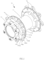
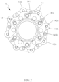
- FIGS. 1 to 3 are the three-dimensional state, front-view state, side-view half-section and partial enlarged state reference diagram of the bicycle hub structure of the present invention, which include:
- a hub 10 the hub 10 is provided with a hub body 11, a ratchet disc 13 and at least two hub disc sets 14, the hub disc sets 14 are respectively provided with an outer hub disc 140 and an inner hub disc 141, the outer diameter of the outer hub 140 is larger than the outer diameter of the inner hub 141, and the outer hub 140 is alternately provided with several fixed convex portions 140A and several recesses 140B, and the fixed convex portions 140A are respectively provided with an outer fixing hole 140a, the inner hub plate 141 is provided with an inner fixing hole 141a in the number of recesses 140B relative to the number of the outer hub plate 140, and the hub plate group 14 is respectively arranged on both sides of the hub body 11, and the ratchet plate 13 is arranged on the hub.
- the outer side of the hub disk assembly 14 on one side of the main body 11.
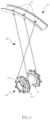
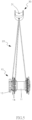
- FIGS 1 to 5 are the three-dimensional state, front-view state, side-view half-section and partial enlarged state of the bicycle hub structure of the present invention, the three-dimensional use state assembled with the spokes and the wheel frame, and the spokes and the wheel frame.
- the hub 10 is provided with hub disc sets 14 on both sides of the hub body 11.
- the hub disc set 14 is provided with an outer hub disc 140 and an inner hub disc 141 at intervals.
- 20 and the wheel frame 30 are assembled, one end of the number of wheel spokes 20 is fixedly combined with the wheel frame 30, and the other end of the number of wheel spokes 20 is fixedly combined with the outer hub disk 140 and the inner hub disk 141 respectively.
- the outer hub 140 and the inner hub 141 are subjected to force to prevent the outer hub 140 or the inner hub 141 from being subjected to excessive force, and the outer hub 140 and the inner hub 141 are arranged at intervals to allow the number of spokes 20.
- the parts will come into contact with each other, reducing friction and affecting the structural strength and service life, so as to achieve the effect of convenient use of the structure and good function of the structure.
- FIG. 3 is a side view of a half-section and a partial enlarged state reference view of the bicycle hub structure of the present invention.
- it further includes several spokes 20 and a wheel frame 30.
- the number of fixed convex portions 140A is provided with an inclined cut surface 140b relative to the side surface of the ratchet plate 14.
- One end of the number of spokes 20 is fixed to the wheel frame 30, and the other end of the number of spokes 20 is fixed to the outer hub 140.
- the outer fixing holes 140a are provided on the fixed convex portions 140A, and the inclined cut surface portion 140b provided on the fixing convex portion 140A prevents friction between the spokes 20 and the fixing convex portions 140A, thereby improving the rigidity and service life of the spokes 20.
- the multiple variability of the present invention is enhanced.
- FIG. 1 is a three-dimensional schematic diagram of the structure of the bicycle hub of the present invention.
- it further includes several spokes 20 and a wheel frame 30.
- the inner hub disk 141 has a fixed hole. Between 141a, there is an outwardly opening avoiding recess 141b, one end of several spokes 20 is fixed on the wheel frame 30, and the other end of the several spokes 20 is fixed on the outer hub 140.
- the avoidance concave portion 141b is used for avoidance when the spokes 20 of the wheel are assembled, so as to facilitate the assembly and fixation, so as to enhance the multiple variability of the present invention.
- FIG. 6 is a reference diagram of a state in which the depth of the troughs of the recesses provided in the inner hub is lower than the outer diameter of the outer fixing holes provided in the outer hub, in a preferred embodiment of the bicycle hub structure of the present invention.
- the recessed portion 141b of the inner hub 141 is provided with a trough 141c, and the depth of the trough 141c is lower than the outer diameter of the outer fixing hole 140a provided in the outer hub 140, when the spokes 20 are fixed on the outer fixing holes 140a of the fixed convex portions 140A of the outer hub 140, the valleys 141c of the recessed portions 141b are used to avoid the spokes 20 when they are assembled, so that the spokes 20 are not in contact with the inner hub 140.
- the contact between the hub disks 141 increases the endurance strength and service life of the spokes 20, so as to increase the multiple variability of the present invention.
- the present invention can indeed achieve the above-mentioned functions and purposes, so the present invention should meet the requirements for a patent application, and an application should be filed in accordance with the law.
Landscapes
- Engineering & Computer Science (AREA)
- Mechanical Engineering (AREA)
- Axle Suspensions And Sidecars For Cycles (AREA)
Abstract
Description
- The present invention relates to a bicycle wheel hub structure, especially a kind of wheel hub which is applied to disperse the force of the steel wire between the bicycle wheel frame and the wheel hub, enhance the pulling force and reduce the friction between the steel wires, which belongs to the technical field.
- Referring to
FIG. 7 , the structure of the conventional bicycle hub is shown therein. Thehub 10 includes ahub body 11 and at least twohub discs 12. Thehub discs 12 are oppositely disposed on both sides of thehub body 11 and are in the same direction as the edge of thehub body 11. Thehub 12 is provided with severalspoke fixing holes 120 at equal intervals. By fitting thehub 10 withseveral spokes 20 and awheel frame 30, thewheel frame 30 is provided with severalpositioning combining holes 31 at intervals. One end of thebar 20 is respectively fixed to the wheel spokefixing holes 120 provided in thehub plate 12, and the other ends of the plurality ofwheel spokes 20 are respectively fixed to the number of positioning and combiningholes 31 provided in thewheel frame 30, and thewheel spokes 20 are crossed. The state is set, and the middle sections of thespokes 20 of each wheel are in contact with each other, and then the weight and force are carried by the front and rear wheels respectively when the bicycle is in contact with the ground, and the overall force will be concentrated on thehub 12 combined with thespokes 20 of the wheels. The number of wheel spokefixing holes 120 is set, so the force around the wheel spoke fixingholes 120 is concentrated, and there is a problem of structural stability. In addition, the wheel spokes 20 in the crossed state contacting and abutting each other in the middle section will be affected by thehub body 11. The friction at the abutting position of thespokes 20 caused by the force also reduces the strength and service life of thespokes 20, so there is a need for improvement. - In view of the problems of insufficient structural stability, structural strength and service life of the conventional bicycle hub structure, the present invention completes the bicycle hub structure of the present invention.
- The main purpose of the present invention is to provide a bicycle wheel hub structure, wherein the wheel hub system includes a wheel hub body, a ratchet disk and at least two wheel hub disk sets. The outer diameter of the outer hub is larger than the outer diameter of the inner hub, and the outer hub is staggered with several fixed protrusions and several recesses, and the fixed protrusions are respectively provided with an outer fixing hole, and the inner hub is relatively outer. The number of hub discs is such that the recessed portions are respectively provided with an inner fixing hole, the hub disc sets are respectively arranged on two sides of the hub body, and the ratchet discs are arranged on the outer side of the hub disc set on one side of the hub body.
- In a preferred embodiment, it further comprises several wheel spokes and a wheel frame, the number of fixed convex portions of the outer hub disk is provided with an inclined cut surface relative to the side surface of the ratchet disk, and one end of the number of wheel spokes is fixed on the wheel frame, the other ends of the spokes are fixed on the outer fixing holes of the fixed convex part of the outer hub, and the inclined cut surface of the fixed convex part prevents the friction between the spokes and the fixed convex part, so as to increase the number of wheels. The rigidity and service life of the spoke structure enhances the multiple variability of the present invention.
- In a preferred embodiment, it further includes a number of spokes and a frame, the inner fixing holes of the inner hub are provided with an outwardly open avoidance recess, one end of the spokes is fixed on the frame, and the spokes are fixed on the frame. When the other end of the strip is fixed in the outer fixing hole of the fixed convex part of the outer wheel hub, the recessed part is used to avoid the several wheel spokes during assembly, which is convenient for assembling and fixing, so as to improve the multi-variability of the present invention.
- In a preferred embodiment, the avoidance recess of the inner hub is further provided with a trough, and the depth of the trough is lower than the outer diameter of the outer fixing hole provided in the outer hub, and the spokes are fixed on the outer hub. When the number of fixed convex parts of the disk are provided with external fixing holes, the valleys of the recessed parts are used to avoid the number of spokes during assembly, so that the spokes do not contact the inner hub disk, and the endurance strength and service life of the spokes are improved. Multiple variations of the invention are provided.
- The two sides of the hub body of the wheel hub are respectively provided with a hub disk group, and the wheel hub disk group is provided with an outer hub disk and an inner hub disk at intervals. The frame is fixedly combined, and the other ends of the spokes are fixedly combined with the outer hub and the inner hub respectively. The force generated by the scattered spokes is applied to the outer hub and the inner hub, so as to avoid the outer hub or the inner hub from being overburdened. The outer hub disc and the inner hub disc are arranged at intervals, so that the spokes of several wheels will come into contact with each other when they are assembled, reducing friction and affecting the strength and service life of the structure, so as to achieve the convenience and function of the structure.
-
- [
FIG. 1 ] is a three-dimensional schematic diagram of the structure of the bicycle wheel hub of the present invention. - [
Fig. 2 ] It is a schematic view of the bicycle wheel hub structure of the present invention as seen before. - [
FIG. 3 ] It is a side view half-section and a partial enlarged state reference view of the bicycle wheel hub structure of the present invention. - [
FIG. 4 ] It is a reference view of the three-dimensional use state of the bicycle hub structure of the present invention assembled with the spokes and the wheel frame. - [
FIG. 5 ] It is a side view of the use state reference diagram of the assembly of the spokes and the wheel frame of the bicycle hub structure of the present invention. - [
Fig. 6 ] is a reference diagram of the state in which the depth of the trough of the recessed portion provided in the inner hub is lower than the outer diameter of the outer fixing hole provided in the outer hub, according to the embodiment of the bicycle hub structure of the present invention. - [
FIG. 7 ] is a reference view of a three-dimensional state of a conventional bicycle hub structure of the bicycle hub structure of the present invention. - In order to enable your examiners to further understand the structure, features and other purposes of the present invention, the following preferred embodiments are described in detail with drawings as follows, but the embodiments described in the drawings are for illustrative purposes. Not the only limitation on patent applications.
- Reference is collectively made to
FIGS. 1 to 3 , which are the three-dimensional state, front-view state, side-view half-section and partial enlarged state reference diagram of the bicycle hub structure of the present invention, which include: - A
hub 10, thehub 10 is provided with ahub body 11, aratchet disc 13 and at least twohub disc sets 14, thehub disc sets 14 are respectively provided with anouter hub disc 140 and aninner hub disc 141, the outer diameter of theouter hub 140 is larger than the outer diameter of theinner hub 141, and theouter hub 140 is alternately provided with several fixedconvex portions 140A andseveral recesses 140B, and the fixedconvex portions 140A are respectively provided with anouter fixing hole 140a, theinner hub plate 141 is provided with aninner fixing hole 141a in the number ofrecesses 140B relative to the number of theouter hub plate 140, and thehub plate group 14 is respectively arranged on both sides of thehub body 11, and theratchet plate 13 is arranged on the hub. The outer side of thehub disk assembly 14 on one side of themain body 11. - Through the cooperation of the above structures, the bicycle wheel hub structure of the present invention is completed.
- Reference is next made to
FIGS 1 to 5 , which are the three-dimensional state, front-view state, side-view half-section and partial enlarged state of the bicycle hub structure of the present invention, the three-dimensional use state assembled with the spokes and the wheel frame, and the spokes and the wheel frame. Referring to the assembled side view of the use state, thehub 10 is provided withhub disc sets 14 on both sides of thehub body 11. Thehub disc set 14 is provided with anouter hub disc 140 and aninner hub disc 141 at intervals. 20 and thewheel frame 30 are assembled, one end of the number ofwheel spokes 20 is fixedly combined with thewheel frame 30, and the other end of the number ofwheel spokes 20 is fixedly combined with theouter hub disk 140 and theinner hub disk 141 respectively. Theouter hub 140 and theinner hub 141 are subjected to force to prevent theouter hub 140 or theinner hub 141 from being subjected to excessive force, and theouter hub 140 and theinner hub 141 are arranged at intervals to allow the number ofspokes 20. During assembly, the parts will come into contact with each other, reducing friction and affecting the structural strength and service life, so as to achieve the effect of convenient use of the structure and good function of the structure. - Reference is again made to
FIG. 3 , which is a side view of a half-section and a partial enlarged state reference view of the bicycle hub structure of the present invention. In a preferred embodiment, it further includesseveral spokes 20 and awheel frame 30. The number of fixedconvex portions 140A is provided with aninclined cut surface 140b relative to the side surface of theratchet plate 14. One end of the number ofspokes 20 is fixed to thewheel frame 30, and the other end of the number ofspokes 20 is fixed to theouter hub 140. Theouter fixing holes 140a are provided on the fixedconvex portions 140A, and the inclinedcut surface portion 140b provided on thefixing convex portion 140A prevents friction between thespokes 20 and the fixingconvex portions 140A, thereby improving the rigidity and service life of thespokes 20. The multiple variability of the present invention is enhanced. - Reference again made back to
FIG. 1 , which is a three-dimensional schematic diagram of the structure of the bicycle hub of the present invention. In a preferred embodiment, it further includesseveral spokes 20 and awheel frame 30. Theinner hub disk 141 has a fixed hole. Between 141a, there is an outwardlyopening avoiding recess 141b, one end ofseveral spokes 20 is fixed on thewheel frame 30, and the other end of theseveral spokes 20 is fixed on theouter hub 140. When thehole 140a is formed, the avoidanceconcave portion 141b is used for avoidance when thespokes 20 of the wheel are assembled, so as to facilitate the assembly and fixation, so as to enhance the multiple variability of the present invention. - Reference is made to
FIG. 6 , which is a reference diagram of a state in which the depth of the troughs of the recesses provided in the inner hub is lower than the outer diameter of the outer fixing holes provided in the outer hub, in a preferred embodiment of the bicycle hub structure of the present invention. Except that therecessed portion 141b of theinner hub 141 is provided with atrough 141c, and the depth of thetrough 141c is lower than the outer diameter of theouter fixing hole 140a provided in theouter hub 140, when thespokes 20 are fixed on theouter fixing holes 140a of the fixedconvex portions 140A of theouter hub 140, thevalleys 141c of the recessedportions 141b are used to avoid thespokes 20 when they are assembled, so that thespokes 20 are not in contact with theinner hub 140. The contact between thehub disks 141 increases the endurance strength and service life of thespokes 20, so as to increase the multiple variability of the present invention. - To sum up, the present invention can indeed achieve the above-mentioned functions and purposes, so the present invention should meet the requirements for a patent application, and an application should be filed in accordance with the law.
Claims (9)
- A bicycle wheel hub structure, comprising:
a hub(10), wherein the hub(10) is provided with a hub body(11), a ratchet disc(12) and at least two hub disc sets(13), the hub disc sets(13) are respectively provided with an outer hub disc(140) and an inner hub disc(141) at intervals, and the outer hub disc(140) is staggered with several fixing convex portions(140A) and the number of recessed parts(140B) is provided, and the fixing convex portions (140A) are respectively provided with an outer fixing hole(140a), and the number of recessed parts(140B) of the inner hub disc(141) relative to the outer hub disc(140) are respectively provided with an inner fixing hole(141a), and the hub disc sets(13) are respectively arranged on the two sides of the hub body(11), and the ratchet disc(12) is arranged on the outer side of the hub disc sets(13) on one side of the hub body(11). - The bicycle wheel hub structure as claim 1, wherein the number fixing convex portion(140A) of the outer hub(140) is provided with an inclined cut surface(140b) relative to the side surface of the ratchet plate(12).
- The bicycle wheel hub structure as claim 1, wherein the inner fixing holes(141a) of the inner hub(141) are provided with outwardly opening avoidance recesses(141b).
- The bicycle wheel hub structure as claim 1, wherein the outer diameter of the outer hub(140) is larger than the outer diameter of the inner hub(141).
- A bicycle wheel hub structure, comprising:a hub(10), the hub(10) is provided with a hub body(11), a ratchet disc(12) and at least two hub disc sets(13), the hub disc sets(13) are respectively provided with an outer hub disc(140) and an inner hub disc(141) at intervals, and the outer hub disc(140) is staggered with several fixing convex portions (140A) and the number of recessed parts(140B) is provided, and the fixed convex portions(140A) are respectively provided with an outer fixing hole(140a), and the number of recessed parts(140B) of the inner hub disc(141) relative to the outer hub disc(140a) are respectively provided with an inner fixing hole(141a), and the hub disc sets(13) are respectively arranged on the two sides of the hub body(11) , and the ratchet disc(12) is arranged on the outside of the hub disc sets(13) on one side of the hub body(11);a number of wheel spokes(20), one end of the wheel spokes(20) is respectively fixed to the outer fixing holes(140a) provided in the number of fixed convex portions (140A) of the outer hub disc(140) and the inner fixing holes(141a) provided in the inner hub disc(141); anda wheel frame(30), the inner space of the wheel frame(30) is fixed with the other ends of the spokes of several wheels(20).
- The bicycle wheel hub structure as claim 5, wherein, the number of fixed convex portions(140A) of the outer hub plate(140) is provided with an inclined cut surface(140b) relative to the side surface of the ratchet plate(12), one end of the number of spokes(20) is fixed on the wheel frame(30), and the other end of the number of spokes(20) is fixed on the number of fixed convex portions (140A) of the outer hub plate(140), the outer fixing holes(140a) are provided on the front part, and the inclined cut surface part(140b) provided on the number fixed convex portions (140A) prevents the contact between the number of wheel spokes(20) and the number fixed convex portions (140A) to generate friction.
- The bicycle wheel hub structure as claim 5, wherein, the inner fixing holes(141a) of the inner hub(141) are provided with outwardly opening avoidance recesses(141b), one end of the spokes(20) is fixed on the wheel frame(30), and the other ends of the spokes(20) are fixed on the fixed convex portions(140A) of the outer hub(140), when an external fixing hole(140a) is provided, the avoidance recess(141b) is used for avoidance when the spokes(20) of several wheels are assembled.
- The bicycle wheel hub structure as claim 5, wherein, the outer diameter of the outer hub(140) is larger than the outer diameter of the inner hub(141).
- The bicycle wheel hub structure as claim 5, wherein, the recessed portion(141b) of the inner hub(141) is further provided with a trough(141c), and the depth of the trough(141c) is lower than the outer diameter of the outer fixing hole(140a) provided on the outer hub(140), and the number of the spokes(20) fixed to the number of the fixed convex portions(140A) of the outer hub(140) is set, when the outer fixing hole(140a) is used, the trough(141c) of the avoidance recess(141b) is used for the avoidance of several spokes(20) during assembly, so that the spokes(20) do not contact the inner hub(141).
Applications Claiming Priority (1)
| Application Number | Priority Date | Filing Date | Title |
|---|---|---|---|
| TW111110723A TWI818480B (en) | 2022-01-11 | 2022-03-23 | Bicycle wheel hub structure |
Publications (3)
| Publication Number | Publication Date |
|---|---|
| EP4249284A1 true EP4249284A1 (en) | 2023-09-27 |
| EP4249284B1 EP4249284B1 (en) | 2025-12-17 |
| EP4249284C0 EP4249284C0 (en) | 2025-12-17 |
Family
ID=82820257
Family Applications (1)
| Application Number | Title | Priority Date | Filing Date |
|---|---|---|---|
| EP23150481.2A Active EP4249284B1 (en) | 2022-03-23 | 2023-01-05 | Bicycle wheel hub structure |
Country Status (3)
| Country | Link |
|---|---|
| US (1) | US20230322021A1 (en) |
| EP (1) | EP4249284B1 (en) |
| CN (1) | CN217227183U (en) |
Citations (4)
| Publication number | Priority date | Publication date | Assignee | Title |
|---|---|---|---|---|
| EP0896886A1 (en) * | 1997-08-13 | 1999-02-17 | Mavic S.A. | Spoke for bicycle wheel, bicycle wheel and production method |
| DE20009502U1 (en) * | 1999-05-28 | 2000-08-17 | Mavic S.A., Saint-Trivier Sur Moignans | Bicycle hub designed to be equipped with a brake disc |
| US20040222692A1 (en) * | 2003-04-25 | 2004-11-11 | Cheng-Hsun Chiang | Multiple-flange bicycle hubs |
| US20080309152A1 (en) * | 2007-06-12 | 2008-12-18 | Salomon S.A. | Wheel including a rim, a hub, and a device for coupling the rim to the hub |
Family Cites Families (6)
| Publication number | Priority date | Publication date | Assignee | Title |
|---|---|---|---|---|
| US586138A (en) * | 1897-07-13 | Means for fastening spokes to vehicle-wheels | ||
| US1601764A (en) * | 1922-05-05 | 1926-10-05 | Morgan William Henry | Metal wheel |
| US20070035176A1 (en) * | 2005-08-09 | 2007-02-15 | Yen-Jiun Lin | Hub for a bicycle |
| US20070241608A1 (en) * | 2006-04-13 | 2007-10-18 | Kun Teng Industry Co., Ltd. | Bicycle hub and assembly of bicycle hub and spokes |
| US20110084541A1 (en) * | 2009-05-30 | 2011-04-14 | Reynolds Cycling Llc | Tri-Flange Hub |
| TWM522862U (en) * | 2016-02-19 | 2016-06-01 | Hubsmith Co Ltd | Bicycle rim |
-
2022
- 2022-04-21 CN CN202220933781.XU patent/CN217227183U/en active Active
- 2022-05-19 US US17/748,874 patent/US20230322021A1/en not_active Abandoned
-
2023
- 2023-01-05 EP EP23150481.2A patent/EP4249284B1/en active Active
Patent Citations (4)
| Publication number | Priority date | Publication date | Assignee | Title |
|---|---|---|---|---|
| EP0896886A1 (en) * | 1997-08-13 | 1999-02-17 | Mavic S.A. | Spoke for bicycle wheel, bicycle wheel and production method |
| DE20009502U1 (en) * | 1999-05-28 | 2000-08-17 | Mavic S.A., Saint-Trivier Sur Moignans | Bicycle hub designed to be equipped with a brake disc |
| US20040222692A1 (en) * | 2003-04-25 | 2004-11-11 | Cheng-Hsun Chiang | Multiple-flange bicycle hubs |
| US20080309152A1 (en) * | 2007-06-12 | 2008-12-18 | Salomon S.A. | Wheel including a rim, a hub, and a device for coupling the rim to the hub |
Also Published As
| Publication number | Publication date |
|---|---|
| EP4249284B1 (en) | 2025-12-17 |
| US20230322021A1 (en) | 2023-10-12 |
| CN217227183U (en) | 2022-08-19 |
| EP4249284C0 (en) | 2025-12-17 |
Similar Documents
| Publication | Publication Date | Title |
|---|---|---|
| US4256346A (en) | Wheels for vehicles, such as motorcycles | |
| US6354668B2 (en) | Bicycle rim with wear indicator | |
| JP3344704B2 (en) | Spoke and rim assemblies, bicycle wheels, bicycle spokes and bicycle rims | |
| KR102609468B1 (en) | Assembled vehicle wheels and disc wheels for such assembled vehicle wheels and methods for producing such wheel discs and assembled vehicle wheels | |
| US4300804A (en) | Hub for a two or three wheel vehicle | |
| EP4249284A1 (en) | Bicycle wheel hub structure | |
| EP0916520A2 (en) | Bicycle wheel | |
| CN106915201B (en) | Half-surface wheel | |
| TWM628988U (en) | Bicycle wheel hub structure | |
| US20030080605A1 (en) | Fabricated vehicle wheel | |
| JPH0694241B2 (en) | Wheel hub | |
| TWI818480B (en) | Bicycle wheel hub structure | |
| JP2001514108A (en) | Bicycle tension spoked wheel assembly and hub therefor | |
| US6871915B2 (en) | Multiple-flange bicycle hubs | |
| US2702725A (en) | Spoke wheel and hub therefor | |
| US7029074B2 (en) | Wheel rim with anchor members connected to spokes | |
| US4585277A (en) | Wire wheel with spokes having crank shaped section | |
| JP7478125B2 (en) | Floating type brake disc and wheel for saddle-type vehicle | |
| CN214138105U (en) | Wheel and have its vehicle | |
| JP2012040947A (en) | Wheel for vehicle | |
| JPS62297549A (en) | brake disc | |
| CN222315743U (en) | Carbon ceramic brake disc suitable for new energy automobile | |
| US20070085413A1 (en) | Spoke assembling structure for a bicycle wheel | |
| CN220517883U (en) | Hub decorative cover and vehicle | |
| JP2024084578A (en) | tire |
Legal Events
| Date | Code | Title | Description |
|---|---|---|---|
| PUAI | Public reference made under article 153(3) epc to a published international application that has entered the european phase |
Free format text: ORIGINAL CODE: 0009012 |
|
| STAA | Information on the status of an ep patent application or granted ep patent |
Free format text: STATUS: THE APPLICATION HAS BEEN PUBLISHED |
|
| AK | Designated contracting states |
Kind code of ref document: A1 Designated state(s): AL AT BE BG CH CY CZ DE DK EE ES FI FR GB GR HR HU IE IS IT LI LT LU LV MC ME MK MT NL NO PL PT RO RS SE SI SK SM TR |
|
| STAA | Information on the status of an ep patent application or granted ep patent |
Free format text: STATUS: REQUEST FOR EXAMINATION WAS MADE |
|
| 17P | Request for examination filed |
Effective date: 20240305 |
|
| RBV | Designated contracting states (corrected) |
Designated state(s): AL AT BE BG CH CY CZ DE DK EE ES FI FR GB GR HR HU IE IS IT LI LT LU LV MC ME MK MT NL NO PL PT RO RS SE SI SK SM TR |
|
| STAA | Information on the status of an ep patent application or granted ep patent |
Free format text: STATUS: EXAMINATION IS IN PROGRESS |
|
| 17Q | First examination report despatched |
Effective date: 20241111 |
|
| GRAP | Despatch of communication of intention to grant a patent |
Free format text: ORIGINAL CODE: EPIDOSNIGR1 |
|
| STAA | Information on the status of an ep patent application or granted ep patent |
Free format text: STATUS: GRANT OF PATENT IS INTENDED |
|
| RIC1 | Information provided on ipc code assigned before grant |
Ipc: B60B 1/00 20060101AFI20250717BHEP Ipc: B60B 1/04 20060101ALI20250717BHEP Ipc: B60B 27/02 20060101ALI20250717BHEP Ipc: B60B 27/00 20060101ALN20250717BHEP |
|
| INTG | Intention to grant announced |
Effective date: 20250731 |
|
| GRAS | Grant fee paid |
Free format text: ORIGINAL CODE: EPIDOSNIGR3 |
|
| GRAA | (expected) grant |
Free format text: ORIGINAL CODE: 0009210 |
|
| STAA | Information on the status of an ep patent application or granted ep patent |
Free format text: STATUS: THE PATENT HAS BEEN GRANTED |
|
| AK | Designated contracting states |
Kind code of ref document: B1 Designated state(s): AL AT BE BG CH CY CZ DE DK EE ES FI FR GB GR HR HU IE IS IT LI LT LU LV MC ME MK MT NL NO PL PT RO RS SE SI SK SM TR |
|
| REG | Reference to a national code |
Ref country code: CH Ref legal event code: F10 Free format text: ST27 STATUS EVENT CODE: U-0-0-F10-F00 (AS PROVIDED BY THE NATIONAL OFFICE) Effective date: 20251217 Ref country code: GB Ref legal event code: FG4D |
|
| REG | Reference to a national code |
Ref country code: DE Ref legal event code: R096 Ref document number: 602023009658 Country of ref document: DE |
|
| U01 | Request for unitary effect filed |
Effective date: 20251222 |
|
| U07 | Unitary effect registered |
Designated state(s): AT BE BG DE DK EE FI FR IT LT LU LV MT NL PT RO SE SI Effective date: 20260109 |
|
| U20 | Renewal fee for the european patent with unitary effect paid |
Year of fee payment: 4 Effective date: 20251222 |
|
| PG25 | Lapsed in a contracting state [announced via postgrant information from national office to epo] |
Ref country code: NO Free format text: LAPSE BECAUSE OF FAILURE TO SUBMIT A TRANSLATION OF THE DESCRIPTION OR TO PAY THE FEE WITHIN THE PRESCRIBED TIME-LIMIT Effective date: 20260317 |
|
| PG25 | Lapsed in a contracting state [announced via postgrant information from national office to epo] |
Ref country code: HR Free format text: LAPSE BECAUSE OF FAILURE TO SUBMIT A TRANSLATION OF THE DESCRIPTION OR TO PAY THE FEE WITHIN THE PRESCRIBED TIME-LIMIT Effective date: 20251217 |
|
| PG25 | Lapsed in a contracting state [announced via postgrant information from national office to epo] |
Ref country code: RS Free format text: LAPSE BECAUSE OF FAILURE TO SUBMIT A TRANSLATION OF THE DESCRIPTION OR TO PAY THE FEE WITHIN THE PRESCRIBED TIME-LIMIT Effective date: 20260317 |