EP4249263A1 - Droplet discharge head and droplet discharge apparatus - Google Patents
Droplet discharge head and droplet discharge apparatus Download PDFInfo
- Publication number
- EP4249263A1 EP4249263A1 EP23162846.2A EP23162846A EP4249263A1 EP 4249263 A1 EP4249263 A1 EP 4249263A1 EP 23162846 A EP23162846 A EP 23162846A EP 4249263 A1 EP4249263 A1 EP 4249263A1
- Authority
- EP
- European Patent Office
- Prior art keywords
- droplet discharge
- shaft
- shaped member
- upper housing
- discharge head
- Prior art date
- Legal status (The legal status is an assumption and is not a legal conclusion. Google has not performed a legal analysis and makes no representation as to the accuracy of the status listed.)
- Granted
Links
Images




Classifications
-
- B—PERFORMING OPERATIONS; TRANSPORTING
- B41—PRINTING; LINING MACHINES; TYPEWRITERS; STAMPS
- B41J—TYPEWRITERS; SELECTIVE PRINTING MECHANISMS, i.e. MECHANISMS PRINTING OTHERWISE THAN FROM A FORME; CORRECTION OF TYPOGRAPHICAL ERRORS
- B41J2/00—Typewriters or selective printing mechanisms characterised by the printing or marking process for which they are designed
- B41J2/005—Typewriters or selective printing mechanisms characterised by the printing or marking process for which they are designed characterised by bringing liquid or particles selectively into contact with a printing material
- B41J2/01—Ink jet
- B41J2/135—Nozzles
- B41J2/14—Structure thereof only for on-demand ink jet heads
- B41J2/14201—Structure of print heads with piezoelectric elements
-
- B—PERFORMING OPERATIONS; TRANSPORTING
- B41—PRINTING; LINING MACHINES; TYPEWRITERS; STAMPS
- B41J—TYPEWRITERS; SELECTIVE PRINTING MECHANISMS, i.e. MECHANISMS PRINTING OTHERWISE THAN FROM A FORME; CORRECTION OF TYPOGRAPHICAL ERRORS
- B41J2202/00—Embodiments of or processes related to ink-jet or thermal heads
- B41J2202/01—Embodiments of or processes related to ink-jet heads
- B41J2202/05—Heads having a valve
Definitions
- Embodiments of the present disclosure relate to a droplet discharge head and a droplet discharge apparatus.
- a droplet discharge apparatus opens and closes minute nozzle orifices formed on a nozzle plate with respective valve elements each disposed at a tip end of a needle valve to discharge pressurized liquid inside the nozzle plate as liquid droplets from the nozzle orifices.
- a rear end of each of the needle valves is connected to a driver, i.e., an actuator, such as a piezoelectric element that extends and contracts.
- the driver extends and contracts to vibrate in a longitudinal direction of the needle valve to open and close the valve element. Accordingly, pressurized ink is discharged as liquid droplets from the nozzle orifice at a moment when the valve element opens.
- a driver that employs an electromagnetic solenoid as described in, for example, Japanese Unexamined Patent Application Publication No. 2020-199659
- a driver that employs a piezoelectric element to drive a needle valve is also known.
- Such a droplet discharge apparatus as described above is used in various fields, for example, to draw a graphic on a body of an automobile with high image quality, or to discharge liquid resist or a deoxyribonucleic acid (DNA) sample as droplets.
- DNA deoxyribonucleic acid
- a needle valve is extremely thin and has a constant length in accordance with a minute nozzle orifice.
- a valve element that serves to open and close the nozzle orifice is disposed at a tip end of the elongated needle valve. For this reason, preferably, the tip end of the needle valve is carefully handled to prevent an impact from the outside from acting on the tip end of the needle valve and prevent, for example, a foreign matter from adhering to the tip end of the needle valve.
- a tip end of a needle valve may be exposed to the outside, for example, in an assembly process or a transportation process of a droplet discharge head, or in an explosion-proof authentication test.
- the droplet discharge head and the needle valve of the droplet discharge head may be damaged.
- a lower housing of a droplet discharge apparatus is removed in an explosion-proof authentication test since the lower housing is a component that contacts solvent
- an object of the present disclosure is to allow a tip end of a needle valve to be housed inside a droplet discharge head as needed to prevent the droplet discharge head or the needle valve from being damaged.
- a droplet discharge head includes a lower housing, an upper housing, a nozzle plate, a shaft-shaped member, and a driver.
- the lower housing includes a flow channel.
- the upper housing is on the lower housing and detachable from the lower housing.
- the nozzle plate is on a lower surface of the lower housing.
- the shaft-shaped member includes a valve element at a tip end of the shaft-shaped member to open and close a nozzle orifice of the droplet discharge head.
- the shaft-shaped member is reciprocatable in the upper housing.
- the driver is disposed in the upper housing and reciprocates the shaft-shaped member in an axial direction of the shaft-shaped member.
- the shaft-shaped member is movable in the axial direction of the shaft-shaped member such that a length of the tip end of the shaft-shaped member protruding from the lower surface of the upper housing is shortened.
- a droplet discharge apparatus that includes the droplet discharge head.
- the tip end of the needle valve can be housed in the droplet discharge head as needed, and damage to the droplet discharge head or the needle valve can be prevented.
- FIG. 1A is a front view of the droplet discharge head 1 according to an embodiment of the present disclosure.
- FIG. 1B is a perspective view of the droplet discharge head 1, viewed from obliquely below.
- a housing 10 of the droplet discharge head 1 includes an upper housing 10a and a lower housing 10b.
- the upper housing 10a is disposed on the lower housing 10b and detachable from the lower housing 10b.
- a cover 20 is fitted onto the upper housing 10a and electrical components are arranged inside the cover 20.
- a connector 2, as an electrical component, is attached to an upper end of the cover 20.
- a nozzle plate 101 made of corrosion-resistant metal such as steel use stainless (SUS) is disposed on a lower surface of the lower housing 10b. Droplets are discharged from minute nozzle orifices 111 formed on the nozzle plate 101.
- SUS steel use stainless
- a flow channel 112 to flow liquid is formed inside the lower housing 10b.
- One end of the flow channel 112 communicates with a supply port 11, and the other end of the flow channel 112 communicates with a collection port 12 (see FIGS. 1A and 1B ).
- the supply port 11 and the collection port 12 are connected to each other via a circulation path L (see FIG. 1A ). Accordingly, pressurized liquid that has been pressurized by a pump P on the circulation path L is supplied to the supply port 11. The pressurized liquid that has not been discharged from the nozzle orifices 111 is collected from the collection port 12 and is then supplied again to the supply port 11 via the circulation path L and the pump P.
- each of the tip ends of the needle valves 113 as shaft-shaped members is exposed from a bearing 121 on a lower surface of the upper housing 10a, as illustrated in the FIGS. 2A and 2B .
- the needle valve 113 is made of corrosion-resistant metal such as steel use stainless (SUS) and is extremely thin, with a diameter of 1 mm or less in a thin portion and a diameter of about 2 mm in a thick portion of the needle valve 113.
- SUS steel use stainless
- a valve element 113a that opens and closes the nozzle orifice 111 is disposed at the tip end of the needle valve 113.
- An elastic O-ring 113b that serves as a sealer and a washer 113c that fixes the O-ring 113b to the needle valve 113 are disposed around the needle valve 113 above the valve element 113a.
- a droplet discharge head in the art, tip ends of needle valves are exposed from an upper housing of the droplet discharge head as illustrated in FIGS. 2A and 2B . For this reason, the droplet discharge head may be damaged, for example, in an assembly process, a transportation process of the droplet discharge head or in an explosion-proof authentication test.
- the tip end of the needle valve 113 is projectable from and retractable into the upper housing 10a. Accordingly, the tip end of the needle valve 113 can be pulled into the upper housing 10a in the assembly process, the transportation process, or the explosion-proof authentication test as needed.
- multiple piezoelectric elements 114 are disposed in the upper housing 10a. Each of the piezoelectric elements 114 drives corresponding one of the valve elements 113a and the needle valves 113. The piezoelectric element 114 is held in a central space 115a of a holder 115.
- the holder 115 includes springs at both an upper end and a lower end of the holder 115, and the piezoelectric element 114 is held such that the piezoelectric element 114 is compressed in an axial direction of the piezoelectric element 114 by the springs.
- a tip end 115b of the holder 115 and a rear end of the needle valve 113 are coupled to each other such that the piezoelectric element 114 and the needle valve 113 are coaxially disposed with each other. Accordingly, when the piezoelectric element 114 contracts in a longitudinal direction of the piezoelectric element 114, the holder 115 also contracts in a longitudinal direction of the holder 115.
- a biasing force acts on the needle valve 113 in a direction in which the nozzle orifice 111 opens.
- the piezoelectric element 114 operates in a d31 mode when a voltage is applied by a voltage application device to drive the needle valve 113 in the direction in which the nozzle orifice 111 opens. In other words, when the voltage is applied to the piezoelectric element 114, the needle valve 113 is driven in the direction in which the nozzle orifice 111 opens.
- the nozzle orifice 111 is closed by the needle valve 113. Accordingly, even when pressurized liquid is supplied to the flow channel 112, the liquid is not discharged from the nozzle orifice 111.
- the piezoelectric element 114 contracts to pull the needle valve 113 via the holder 115.
- the valve element 113a of the needle valve 113 is separated from the nozzle orifice 1 1 1 to open the nozzle orifice 111. Accordingly, the pressurized liquid supplied to the flow channel 112 is discharged as droplets from the nozzle orifice 111.
- the piezoelectric element 114 may operate in a d33 mode in which the piezoelectric element 114 extends in a direction in which the needle valve 113 is closed when a voltage is applied to the piezoelectric element 114.
- the valve element 113a of the needle valve 113 is pressed against the nozzle orifice 111 to close the nozzle orifice 111 in a state in which a voltage is applied to the piezoelectric element 114.
- the valve element 113a of the needle valve 113 moves in the direction in which the valve element 113a opens to open the nozzle orifice 111.
- the d33 mode of the piezoelectric element 114 has high responsiveness and large amount of displacement. Therefore, the d33 mode is suitable in the case where it is desired to enhance the responsiveness of the needle valve 113 when the needle valve 113 opens and closes and reduce variations in the droplet discharge speed and the amount of the droplets discharged from the nozzle orifice 111.
- Each of the holders 115 is disposed in the upper housing 10a such that the position of the holder 115 is adjustable in an up-and-down direction in FIGS. 3A and 3B .
- the holder 115 is biased upward by a compression spring 116 as a biasing member disposed in the upper housing 10a.
- the compression spring 116 moves the needle valve 113 upward as illustrated in FIG. 3B together with the holder 115 at a moment when a later-described securing screw 124 is loosened.
- the needle valve 113 may also be manually moved upward as illustrated in FIG. 3B without the compression spring 116.
- a rear end 115c of the holder 115 is positioned relative to and secured to the upper housing 10a by the securing screw 124.
- An internally-threaded hole 115d is disposed in the rear end 115c of each of the holders 115 in a direction orthogonal to the axial direction of the holder 115, and a tip end of the securing screw 124 is screwed into the internally-threaded hole 115d.
- a special screw such as a Torx (registered trademark) screw can be used as the securing screw 124 in a case in which it is desired to prevent the position of the needle valve 113 from being easily changed or in a case in which it is desired to allow only an operator having a specific authority to change the position of the needle valve 113.
- Torx registered trademark
- elongated holes 30 elongated in the axial direction of the holder 115 are formed, and the securing screws 124 are inserted through the respective elongated holes 30. Loosening the securing screw 124 allows the holder 115 to move in an up-and-down direction in FIGS. 4A and 4B .
- the securing screw 124 is fastened relative to and fixed to the elongated hole 30 at a position at which a predetermined clearance ⁇ is formed between the valve element 113a and the nozzle orifice 111, as illustrated in FIG. 3A .
- the droplet discharge head 1 is delivered as a product, in the state as described above.
- the securing screw 124 is loosened, as illustrated in FIGS. 3B and 4B , the securing screw 124 moves to and stops at the upper end of the elongated hole 30 by the biasing force of the compression spring 116.
- the valve element 113a at the tip end of the needle valve 113 can be quickly pulled into the bearing 121 to a position corresponding to the lower surface of the upper housing 10a as illustrated in FIG. 3B .
- the length of the tip end of the needle valve 113, including the valve element 113a, that protrudes from the lower surface of the upper housing 10a can be shortened.
- the tip end of the needle valve 113 and the valve element 113a are not damaged by, for example, an impact from outside.
- an object such as a foreign matter can be prevented from adhering to the valve element 113a.
- the holder 115 and the needle valve 113 are disposed such that the holder 115 and the needle valve 113 are movable in the axial direction of the holder 115 by moving the securing screw 124 when the piezoelectric element 114 is not driven. Accordingly, the positions of the holder 115 and the needle valve 113 can be adjusted without applying a voltage to the piezoelectric element 114.
- the tip end of the needle valve 113 is sufficiently retracted into the upper housing 10a as illustrated in FIG. 3B .
- a case in which the tip end of the needle valve 113 is partially retracted into the upper housing 10a from the state illustrated in FIG. 3A is also included in the scope of embodiments of the present disclosure.
- FIG. 5 is a perspective view of the droplet discharge apparatus 500 according to the present embodiment.
- FIG. 7 is a perspective view of a driver of the droplet discharge apparatus 500 according to the present embodiment.
- the droplet discharge apparatus 500 includes a movable frame unit 802 installed to face a print object 700 having a curved surface such as a hood of a vehicle.
- a movable unit 813 is attached to a right frame 811 and a left frame 810 of a frame unit 802 such that the movable unit 813 is bridged between the right frame 811 and the left frame 810.
- the movable unit 813 is movable in the vertical direction, i.e., a direction indicated by arrow Y in FIG. 5 .
- the movable unit 813 includes a driver 803 and a droplet discharger 501.
- the driver 803 includes a built-in motor to allow the driver 803 to be reciprocally movable on the movable unit 813 in a horizontal direction, i.e., a direction indicated by arrow X in FIG. 5 .
- the droplet discharger 501 is attached to the driver 803 and discharges liquid toward the print object 700.
- the droplet discharge apparatus 500 also includes a controller 805 and an information processing device 806 such as a personal computer (PC) that issues instructions to the controller 805.
- the controller 805 controls discharge of liquid from the droplet discharger 501, reciprocal movement of the driver 803, and lifting and lowering of the movable unit 813.
- the information processing device 806 is connected to a database (DB) unit 807 that records and stores data of the print object 700 such as a shape and a size of the print object 700.
- DB database
- the frame unit 802 further includes an upper frame 808, a lower frame 809, the right frame 811, and the left frame 810 that are formed of, for example, columnar metal.
- the frame unit 802 further includes a right leg 812b and a left leg 812a that are attached at right angles and horizontally to both sides of the lower frame 809 to cause the frame unit 802 stand by itself.
- the movable unit 813 bridged between the right frame 811 and the left frame 810 is movable in the vertical direction while supporting the driver 803.
- the print object 700 is disposed perpendicular to a liquid discharge direction indicated by arrow Z in FIG. 5 .
- the print object 700 is disposed to face a flat surface formed by the upper frame 808, the lower frame 809, the right frame 811, and the left frame 810 of the frame unit 802.
- the back side of a printing area of the print object 700 can be attracted and held at a predetermined position at which printing is to be performed by, for example, a chuck attached to a leading end of an arm of an articulated arm robot to locate the print object 700.
- a chuck attached to a leading end of an arm of an articulated arm robot to locate the print object 700.
- the driver 803 is disposed to be reciprocally movable in the horizontal direction, i.e., X direction, on the movable unit 813.
- the movable unit 813 includes a rail 830, a rack gear 831, a linear guide 832, a pinion gear unit 833, a motor 834, and a rotary encoder 835.
- the rail 830 horizontally extends between the right frame 811 and the left frame 810 of the frame unit 802.
- the rack gear 831 is disposed parallel to the rail 830.
- the linear guide 832 is externally fitted to a part of the rail 830 to be movable while sliding.
- the pinion gear unit 833 is connected to the linear guide 832 and meshed with the rack gear 831.
- the motor 834 is provided with a decelerator 836 and rotationally drives the pinion gear unit 833.
- the rotary encoder 835 detects a printing position.
- Driving the motor 834 to rotate forward or reverse causes the droplet discharger 501 to move in the right direction or the left direction along the movable unit 813.
- the driver 803 functions as a driving mechanism of the droplet discharger 501 in the X direction in FIGS. 5 and 7 .
- Limit switches 837a and 837b are attached to both sides of a housing of the decelerator 836.
- the droplet discharger 501 includes, for example, the multiple droplet discharge heads 1 that discharge liquid of different colors of black, cyan, magenta, yellow, and white, or a droplet discharge head 1 having multiple nozzle rows. Liquid of each color is supplied under pressure from a liquid tank to the corresponding one of the droplet discharge heads 1 of the droplet discharger 501 or corresponding one of nozzle rows of the droplet discharge head 1.
- the movable unit 813 is moved in the Y direction and the droplet discharger 501 is moved in the X direction to print a desired image on the print object 700.
- the above-described term "droplet discharge apparatus" is not limited to an apparatus that discharge liquid to visualize meaningful images, such as letters or figures.
- the droplet discharge apparatus may be an apparatus to form such as meaningless patterns, uniform layer of paint or fabricate three-dimensional images.
- the compression spring 116 that biases the needle valve 113 upward may be replaced with a plate spring having a similar biasing force or a driver using, for example, a motor.
- the housing closer to the nozzle plate 101 is defined as the lower housing 10b and the housing farther from the nozzle plate 101 is defined as the upper housing 10a.
- the terms “upper” and “lower” do not limit the relative positions and arrangement positions of components in the direction of gravity during manufacture and use of the droplet discharge head.
- the piezoelectric element 114 is replaceable with another driver that extends and contracts in the longitudinal direction.
- a piston that extends and contracts in the longitudinal direction by an electromagnetic solenoid may be used instead of the piezoelectric element 114.
Landscapes
- Coating Apparatus (AREA)
- Particle Formation And Scattering Control In Inkjet Printers (AREA)
Abstract
Description
- Embodiments of the present disclosure relate to a droplet discharge head and a droplet discharge apparatus.
- A droplet discharge apparatus is known that opens and closes minute nozzle orifices formed on a nozzle plate with respective valve elements each disposed at a tip end of a needle valve to discharge pressurized liquid inside the nozzle plate as liquid droplets from the nozzle orifices. A rear end of each of the needle valves is connected to a driver, i.e., an actuator, such as a piezoelectric element that extends and contracts. The driver extends and contracts to vibrate in a longitudinal direction of the needle valve to open and close the valve element. Accordingly, pressurized ink is discharged as liquid droplets from the nozzle orifice at a moment when the valve element opens.
- In addition to the driver that employs an electromagnetic solenoid as described in, for example,
Japanese Unexamined Patent Application Publication No. 2020-199659 - A needle valve is extremely thin and has a constant length in accordance with a minute nozzle orifice. A valve element that serves to open and close the nozzle orifice is disposed at a tip end of the elongated needle valve. For this reason, preferably, the tip end of the needle valve is carefully handled to prevent an impact from the outside from acting on the tip end of the needle valve and prevent, for example, a foreign matter from adhering to the tip end of the needle valve.
- However, a tip end of a needle valve may be exposed to the outside, for example, in an assembly process or a transportation process of a droplet discharge head, or in an explosion-proof authentication test. When an impact is applied to the tip end of the needle valve in a state in which the tip end of the needle valve is exposed to the outside, the droplet discharge head and the needle valve of the droplet discharge head may be damaged. A lower housing of a droplet discharge apparatus is removed in an explosion-proof authentication test since the lower housing is a component that contacts solvent
- In the explosion-proof authentication test, a steel ball is dropped onto the droplet discharge head from which the lower housing covering the tip end of the needle valve is removed to test impact resistance of the droplet discharge head. However, the tip end of the needle valve may be damaged by impact of the steel ball depending on how the steel ball is dropped onto the droplet discharge head.
- In light of the above-described disadvantages, an object of the present disclosure is to allow a tip end of a needle valve to be housed inside a droplet discharge head as needed to prevent the droplet discharge head or the needle valve from being damaged.
- To solve the above problem, according to an embodiment of the present disclosure, a droplet discharge head includes a lower housing, an upper housing, a nozzle plate, a shaft-shaped member, and a driver. The lower housing includes a flow channel. The upper housing is on the lower housing and detachable from the lower housing. The nozzle plate is on a lower surface of the lower housing. The shaft-shaped member includes a valve element at a tip end of the shaft-shaped member to open and close a nozzle orifice of the droplet discharge head. The shaft-shaped member is reciprocatable in the upper housing. The driver is disposed in the upper housing and reciprocates the shaft-shaped member in an axial direction of the shaft-shaped member. The shaft-shaped member is movable in the axial direction of the shaft-shaped member such that a length of the tip end of the shaft-shaped member protruding from the lower surface of the upper housing is shortened.
- According to an embodiment of the present disclosure, a droplet discharge apparatus that includes the droplet discharge head.
- According to embodiments of the present disclosure, the tip end of the needle valve can be housed in the droplet discharge head as needed, and damage to the droplet discharge head or the needle valve can be prevented.
- A more complete appreciation of the disclosure and many of the attendant advantages and features thereof can be readily obtained and understood from the following detailed description with reference to the accompanying drawings, wherein:
-
FIG. 1A is a front view of a droplet discharge head according to an embodiment of the present disclosure; -
FIG. 1B is a perspective view of the droplet discharge head ofFIG. 1A as viewed from obliquely below; -
FIG. 2A is a front view of the droplet discharge head ofFIG. 1A from which a lower housing of the droplet discharge head is detached; -
FIG. 2B is an enlarged perspective view of a lower end of the droplet discharge head ofFIG. 1A ; -
FIG. 3A is a cross-sectional view of a droplet discharge head, in which valve elements of the droplet discharge head are protruded, according to an embodiment of the present disclosure; -
FIG. 3B is a cross-sectional view of the droplet discharge head ofFIG. 3A , in which the valve elements of the droplet discharge head are retracted; -
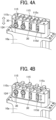
FIG. 4A is a perspective view of a rear end of a droplet discharge head in which the valve elements of the droplet discharge head are protruded, according to an embodiment of the present disclosure; -
FIG. 4B is a perspective view of the rear end of the droplet discharge head ofFIG. 4A in which the valve elements of the droplet discharge head are retracted, according to an embodiment of the present disclosure; -
FIG. 5 is a perspective view of a droplet discharge apparatus according to an embodiment of the present disclosure; -
FIG. 6 is a diagram illustrating a block diagram of a controller provided for the droplet discharge apparatus, according to an embodiment of the present disclosure; and -
FIG. 7 is a perspective view of a driver of the droplet discharge apparatus ofFIG. 5 , according to an embodiment of the present disclosure. - The accompanying drawings are intended to depict embodiments of the present invention and should not be interpreted to limit the scope thereof. The accompanying drawings are not to be considered as drawn to scale unless explicitly noted. Also, identical or similar reference numerals designate identical or similar components throughout the several views.
- In describing embodiments illustrated in the drawings, specific terminology is employed for the sake of clarity. However, the disclosure of this specification is not intended to be limited to the specific terminology so selected and it is to be understood that each specific element includes all technical equivalents that have a similar function, operate in a similar manner, and achieve a similar result.
- Referring now to the drawings, embodiments of the present disclosure are described below. As used herein, the singular forms "a," "an," and "the" are intended to include the plural forms as well, unless the context clearly indicates otherwise.
- Embodiments of the present disclosure are described below with reference to the attached drawings.
FIG. 1A is a front view of thedroplet discharge head 1 according to an embodiment of the present disclosure.FIG. 1B is a perspective view of thedroplet discharge head 1, viewed from obliquely below. - A
housing 10 of thedroplet discharge head 1 includes anupper housing 10a and alower housing 10b. Theupper housing 10a is disposed on thelower housing 10b and detachable from thelower housing 10b. Acover 20 is fitted onto theupper housing 10a and electrical components are arranged inside thecover 20. Aconnector 2, as an electrical component, is attached to an upper end of thecover 20. - A
nozzle plate 101 made of corrosion-resistant metal such as steel use stainless (SUS) is disposed on a lower surface of thelower housing 10b. Droplets are discharged fromminute nozzle orifices 111 formed on thenozzle plate 101. - As illustrated in
FIGS. 3A and 3B , aflow channel 112 to flow liquid is formed inside thelower housing 10b. One end of theflow channel 112 communicates with asupply port 11, and the other end of theflow channel 112 communicates with a collection port 12 (seeFIGS. 1A and 1B ). - The
supply port 11 and thecollection port 12 are connected to each other via a circulation path L (seeFIG. 1A ). Accordingly, pressurized liquid that has been pressurized by a pump P on the circulation path L is supplied to thesupply port 11. The pressurized liquid that has not been discharged from thenozzle orifices 111 is collected from thecollection port 12 and is then supplied again to thesupply port 11 via the circulation path L and the pump P. - When the above-described
lower housing 10b is detached from theupper housing 10a, each of the tip ends of theneedle valves 113 as shaft-shaped members is exposed from a bearing 121 on a lower surface of theupper housing 10a, as illustrated in theFIGS. 2A and 2B . Theneedle valve 113 is made of corrosion-resistant metal such as steel use stainless (SUS) and is extremely thin, with a diameter of 1 mm or less in a thin portion and a diameter of about 2 mm in a thick portion of theneedle valve 113. Each of thethin needle valves 113 is exposed from the bearing 121 on theupper housing 10a by, for example, 1 to 20 mm. - A
valve element 113a that opens and closes thenozzle orifice 111 is disposed at the tip end of theneedle valve 113. An elastic O-ring 113b that serves as a sealer and awasher 113c that fixes the O-ring 113b to theneedle valve 113 are disposed around theneedle valve 113 above thevalve element 113a. - In a droplet discharge head in the art, tip ends of needle valves are exposed from an upper housing of the droplet discharge head as illustrated in
FIGS. 2A and 2B . For this reason, the droplet discharge head may be damaged, for example, in an assembly process, a transportation process of the droplet discharge head or in an explosion-proof authentication test. - In the present embodiment, as illustrated in
FIGS. 3A and 3B , the tip end of theneedle valve 113 is projectable from and retractable into theupper housing 10a. Accordingly, the tip end of theneedle valve 113 can be pulled into theupper housing 10a in the assembly process, the transportation process, or the explosion-proof authentication test as needed. - As illustrated in
FIGS. 3A and 3B , multiplepiezoelectric elements 114 are disposed in theupper housing 10a. Each of thepiezoelectric elements 114 drives corresponding one of thevalve elements 113a and theneedle valves 113. Thepiezoelectric element 114 is held in acentral space 115a of aholder 115. - The
holder 115 includes springs at both an upper end and a lower end of theholder 115, and thepiezoelectric element 114 is held such that thepiezoelectric element 114 is compressed in an axial direction of thepiezoelectric element 114 by the springs. Atip end 115b of theholder 115 and a rear end of theneedle valve 113 are coupled to each other such that thepiezoelectric element 114 and theneedle valve 113 are coaxially disposed with each other. Accordingly, when thepiezoelectric element 114 contracts in a longitudinal direction of thepiezoelectric element 114, theholder 115 also contracts in a longitudinal direction of theholder 115. Thus, a biasing force acts on theneedle valve 113 in a direction in which thenozzle orifice 111 opens. - The
piezoelectric element 114 operates in a d31 mode when a voltage is applied by a voltage application device to drive theneedle valve 113 in the direction in which thenozzle orifice 111 opens. In other words, when the voltage is applied to thepiezoelectric element 114, theneedle valve 113 is driven in the direction in which thenozzle orifice 111 opens. - Accordingly, when no voltage is applied to the
piezoelectric element 114, thenozzle orifice 111 is closed by theneedle valve 113. Accordingly, even when pressurized liquid is supplied to theflow channel 112, the liquid is not discharged from thenozzle orifice 111. - When a voltage is applied to the
piezoelectric element 114, thepiezoelectric element 114 contracts to pull theneedle valve 113 via theholder 115. Thus, thevalve element 113a of theneedle valve 113 is separated from thenozzle orifice 1 1 1 to open thenozzle orifice 111. Accordingly, the pressurized liquid supplied to theflow channel 112 is discharged as droplets from thenozzle orifice 111. - The
piezoelectric element 114 may operate in a d33 mode in which thepiezoelectric element 114 extends in a direction in which theneedle valve 113 is closed when a voltage is applied to thepiezoelectric element 114. When thepiezoelectric element 114 operates in the d33 mode, thevalve element 113a of theneedle valve 113 is pressed against thenozzle orifice 111 to close thenozzle orifice 111 in a state in which a voltage is applied to thepiezoelectric element 114. - When droplets are discharged, application of a voltage to the
piezoelectric element 114 is stopped or the voltage is decreased. Accordingly, thevalve element 113a of theneedle valve 113 moves in the direction in which thevalve element 113a opens to open thenozzle orifice 111. The d33 mode of thepiezoelectric element 114 has high responsiveness and large amount of displacement. Therefore, the d33 mode is suitable in the case where it is desired to enhance the responsiveness of theneedle valve 113 when theneedle valve 113 opens and closes and reduce variations in the droplet discharge speed and the amount of the droplets discharged from thenozzle orifice 111. - Each of the
holders 115 is disposed in theupper housing 10a such that the position of theholder 115 is adjustable in an up-and-down direction inFIGS. 3A and 3B . Theholder 115 is biased upward by acompression spring 116 as a biasing member disposed in theupper housing 10a. Thecompression spring 116 moves theneedle valve 113 upward as illustrated inFIG. 3B together with theholder 115 at a moment when a later-described securingscrew 124 is loosened. Theneedle valve 113 may also be manually moved upward as illustrated inFIG. 3B without thecompression spring 116. - A
rear end 115c of theholder 115 is positioned relative to and secured to theupper housing 10a by the securingscrew 124. An internally-threadedhole 115d is disposed in therear end 115c of each of theholders 115 in a direction orthogonal to the axial direction of theholder 115, and a tip end of the securingscrew 124 is screwed into the internally-threadedhole 115d. Note that a special screw such as a Torx (registered trademark) screw can be used as the securingscrew 124 in a case in which it is desired to prevent the position of theneedle valve 113 from being easily changed or in a case in which it is desired to allow only an operator having a specific authority to change the position of theneedle valve 113. - In an upper end of the
upper housing 10a, as illustrated inFIGS. 4A and 4B ,elongated holes 30 elongated in the axial direction of theholder 115 are formed, and the securingscrews 124 are inserted through the respectiveelongated holes 30. Loosening the securingscrew 124 allows theholder 115 to move in an up-and-down direction inFIGS. 4A and 4B . - The securing
screw 124 is fastened relative to and fixed to theelongated hole 30 at a position at which a predetermined clearance δ is formed between thevalve element 113a and thenozzle orifice 111, as illustrated inFIG. 3A . Thedroplet discharge head 1 is delivered as a product, in the state as described above. When the securingscrew 124 is loosened, as illustrated inFIGS. 3B and4B , the securingscrew 124 moves to and stops at the upper end of theelongated hole 30 by the biasing force of thecompression spring 116. - Accordingly, the
valve element 113a at the tip end of theneedle valve 113 can be quickly pulled into the bearing 121 to a position corresponding to the lower surface of theupper housing 10a as illustrated inFIG. 3B . In other words, the length of the tip end of theneedle valve 113, including thevalve element 113a, that protrudes from the lower surface of theupper housing 10a can be shortened. For this reason, in a state as illustrated inFIG. 3B , even if thelower housing 10b is detached from theupper housing 10a, the tip end of theneedle valve 113 and thevalve element 113a are not damaged by, for example, an impact from outside. In addition, an object such as a foreign matter can be prevented from adhering to thevalve element 113a. - The
holder 115 and theneedle valve 113 are disposed such that theholder 115 and theneedle valve 113 are movable in the axial direction of theholder 115 by moving the securingscrew 124 when thepiezoelectric element 114 is not driven. Accordingly, the positions of theholder 115 and theneedle valve 113 can be adjusted without applying a voltage to thepiezoelectric element 114. - Preferably, the tip end of the
needle valve 113 is sufficiently retracted into theupper housing 10a as illustrated inFIG. 3B . However, a case in which the tip end of theneedle valve 113 is partially retracted into theupper housing 10a from the state illustrated inFIG. 3A is also included in the scope of embodiments of the present disclosure. - Next, a
droplet discharge apparatus 500 that employs thedroplet discharge head 1 ofFIG. 1A according to an embodiment of the present disclosure is described with reference toFIGS. 5, 6 and7 .FIG. 5 is a perspective view of thedroplet discharge apparatus 500 according to the present embodiment.FIG. 7 is a perspective view of a driver of thedroplet discharge apparatus 500 according to the present embodiment. - The
droplet discharge apparatus 500 includes amovable frame unit 802 installed to face aprint object 700 having a curved surface such as a hood of a vehicle. Amovable unit 813 is attached to aright frame 811 and aleft frame 810 of aframe unit 802 such that themovable unit 813 is bridged between theright frame 811 and theleft frame 810. Themovable unit 813 is movable in the vertical direction, i.e., a direction indicated by arrow Y inFIG. 5 . - The
movable unit 813 includes adriver 803 and adroplet discharger 501. Thedriver 803 includes a built-in motor to allow thedriver 803 to be reciprocally movable on themovable unit 813 in a horizontal direction, i.e., a direction indicated by arrow X inFIG. 5 . Thedroplet discharger 501 is attached to thedriver 803 and discharges liquid toward theprint object 700. - The
droplet discharge apparatus 500 also includes acontroller 805 and aninformation processing device 806 such as a personal computer (PC) that issues instructions to thecontroller 805. Thecontroller 805 controls discharge of liquid from thedroplet discharger 501, reciprocal movement of thedriver 803, and lifting and lowering of themovable unit 813. Theinformation processing device 806 is connected to a database (DB)unit 807 that records and stores data of theprint object 700 such as a shape and a size of theprint object 700. - The
frame unit 802 further includes anupper frame 808, alower frame 809, theright frame 811, and theleft frame 810 that are formed of, for example, columnar metal. Theframe unit 802 further includes aright leg 812b and aleft leg 812a that are attached at right angles and horizontally to both sides of thelower frame 809 to cause theframe unit 802 stand by itself. Themovable unit 813 bridged between theright frame 811 and theleft frame 810 is movable in the vertical direction while supporting thedriver 803. - The
print object 700 is disposed perpendicular to a liquid discharge direction indicated by arrow Z inFIG. 5 . In other words, theprint object 700 is disposed to face a flat surface formed by theupper frame 808, thelower frame 809, theright frame 811, and theleft frame 810 of theframe unit 802. In such a case, the back side of a printing area of theprint object 700 can be attracted and held at a predetermined position at which printing is to be performed by, for example, a chuck attached to a leading end of an arm of an articulated arm robot to locate theprint object 700. Using the above-described articulated arm robot allows theprint object 700 to be accurately located at a position at which printing is to be performed and the posture of theprint object 700 to be changed where appropriate. - As illustrated in
FIG. 5 , thedriver 803 is disposed to be reciprocally movable in the horizontal direction, i.e., X direction, on themovable unit 813. As illustrated inFIG. 7 , themovable unit 813 includes arail 830, arack gear 831, alinear guide 832, apinion gear unit 833, amotor 834, and arotary encoder 835. Therail 830 horizontally extends between theright frame 811 and theleft frame 810 of theframe unit 802. Therack gear 831 is disposed parallel to therail 830. Thelinear guide 832 is externally fitted to a part of therail 830 to be movable while sliding. Thepinion gear unit 833 is connected to thelinear guide 832 and meshed with therack gear 831. Themotor 834 is provided with adecelerator 836 and rotationally drives thepinion gear unit 833. Therotary encoder 835 detects a printing position. - Driving the
motor 834 to rotate forward or reverse causes thedroplet discharger 501 to move in the right direction or the left direction along themovable unit 813. Thedriver 803 functions as a driving mechanism of thedroplet discharger 501 in the X direction inFIGS. 5 and7 .Limit switches decelerator 836. - The
droplet discharger 501 includes, for example, the multiple droplet discharge heads 1 that discharge liquid of different colors of black, cyan, magenta, yellow, and white, or adroplet discharge head 1 having multiple nozzle rows. Liquid of each color is supplied under pressure from a liquid tank to the corresponding one of the droplet discharge heads 1 of thedroplet discharger 501 or corresponding one of nozzle rows of thedroplet discharge head 1. - In the
droplet discharge apparatus 500, themovable unit 813 is moved in the Y direction and thedroplet discharger 501 is moved in the X direction to print a desired image on theprint object 700. The above-described term "droplet discharge apparatus" is not limited to an apparatus that discharge liquid to visualize meaningful images, such as letters or figures. For example, the droplet discharge apparatus may be an apparatus to form such as meaningless patterns, uniform layer of paint or fabricate three-dimensional images. - Although some embodiments of the present disclosure have been described above, embodiments of the present disclosure are not limited to the embodiments described above, and a variety of modifications can be made within the scope of the present disclosure. For example, the
compression spring 116 that biases theneedle valve 113 upward may be replaced with a plate spring having a similar biasing force or a driver using, for example, a motor. - Note that in the above-described embodiments of the present disclosure, the housing closer to the
nozzle plate 101 is defined as thelower housing 10b and the housing farther from thenozzle plate 101 is defined as theupper housing 10a. However, the terms "upper" and "lower" do not limit the relative positions and arrangement positions of components in the direction of gravity during manufacture and use of the droplet discharge head. - Further, the
piezoelectric element 114 is replaceable with another driver that extends and contracts in the longitudinal direction. For example, a piston that extends and contracts in the longitudinal direction by an electromagnetic solenoid may be used instead of thepiezoelectric element 114. - The above-described embodiments are illustrative and do not limit the present disclosure. Thus, numerous additional modifications and variations are possible in light of the above teachings. For example, elements and/or features of different illustrative embodiments may be combined with each other and/or substituted for each other within the scope of the present disclosure.
Claims (7)
- A droplet discharge head (1) comprising:a lower housing (10b) including a flow channel (112);an upper housing (10a) on the lower housing (10b), the upper housing (10a) detachable from the lower housing (10b);a nozzle plate (101) on a lower surface of the lower housing (10b);a shaft-shaped member (113) including a valve element (113a) at a tip end of the shaft-shaped member (113) to open and close a nozzle orifice (111) of the droplet discharge head (1), the shaft-shaped member (113) being reciprocatable in the upper housing (10a); anda driver (114) in the upper housing (10a) to reciprocate the shaft-shaped member (113) in an axial direction of the shaft-shaped member (113),the shaft-shaped member (113) being movable in the axial direction of the shaft-shaped member (113) such that a length of the tip end of the shaft-shaped member (113) protruding from the lower surface of the upper housing (10a) is shortened.
- The droplet discharge head (1) according to claim 1, further comprising
a biasing member (116) to bias the shaft-shaped member (113) toward the upper housing (10a). - The droplet discharge head (1) according to claim 2,wherein the driver (114) includes a piezoelectric element (114) and a holder (115) to hold the piezoelectric element, andwherein the shaft-shaped member (113) is positioned when a rear end (115c) of the holder (115) is positioned relative to and secured to the upper housing (10a).
- The droplet discharge head (1) according to claim 3,wherein the upper housing (10a) includes an elongated hole (115d) at the rear end of the upper housing (10a), andwherein the holder (115) is positioned relative to and secured to the upper housing (10a) when a securing screw (124) inserted in the elongated hole (115d) is screwed into the rear end of the holder (115).
- The droplet discharge head (1) according to claim 4,
wherein the biasing member (116) biases the shaft-shaped member (113) such that the shaft-shaped member (113) moves toward the upper housing (10a) to shorten the length of the tip end of the shaft-shaped member (113) protruding from the lower surface of the upper housing (10a) when the securing screw (124) is loosened. - The droplet discharge head (1) according to any one of claims 1 to 5,
wherein the shaft-shaped member (113) is movable in the axial direction of the shaft-shaped member (113) when the driver (114) is not driven. - A droplet discharge apparatus (500) comprising
the droplet discharge head (1) according to any one of claims 1 to 6.
Applications Claiming Priority (1)
| Application Number | Priority Date | Filing Date | Title |
|---|---|---|---|
| JP2022045059A JP7825809B2 (en) | 2022-03-22 | 2022-03-22 | Droplet ejection head and droplet ejection device |
Publications (2)
| Publication Number | Publication Date |
|---|---|
| EP4249263A1 true EP4249263A1 (en) | 2023-09-27 |
| EP4249263B1 EP4249263B1 (en) | 2025-10-08 |
Family
ID=85704822
Family Applications (1)
| Application Number | Title | Priority Date | Filing Date |
|---|---|---|---|
| EP23162846.2A Active EP4249263B1 (en) | 2022-03-22 | 2023-03-20 | Droplet discharge head and droplet discharge apparatus |
Country Status (4)
| Country | Link |
|---|---|
| US (1) | US12325235B2 (en) |
| EP (1) | EP4249263B1 (en) |
| JP (1) | JP7825809B2 (en) |
| ES (1) | ES3054423T3 (en) |
Families Citing this family (1)
| Publication number | Priority date | Publication date | Assignee | Title |
|---|---|---|---|---|
| JP2024130575A (en) | 2023-03-15 | 2024-09-30 | 株式会社リコー | Liquid ejection head and liquid ejection device |
Citations (4)
| Publication number | Priority date | Publication date | Assignee | Title |
|---|---|---|---|---|
| EP0398000A1 (en) * | 1989-04-17 | 1990-11-22 | Komori Corporation | Method of controlling head in image recording apparatus |
| EP2732883A1 (en) * | 2011-07-11 | 2014-05-21 | Musashi Engineering, Inc. | Droplet discharge device and method |
| JP2020199659A (en) | 2019-06-07 | 2020-12-17 | セーレン株式会社 | Inkjet head and inkjet recording device |
| WO2021191728A1 (en) * | 2020-03-23 | 2021-09-30 | Ricoh Company, Ltd. | Discharge head, discharge unit, and liquid discharge apparatus |
Family Cites Families (6)
| Publication number | Priority date | Publication date | Assignee | Title |
|---|---|---|---|---|
| JPH08164611A (en) | 1995-06-23 | 1996-06-25 | Ricoh Co Ltd | Liquid jet recording method |
| US7378837B2 (en) | 2004-06-07 | 2008-05-27 | General Electric Company | Method and system for calibrating a micro-electromechanical system (MEMS) based sensor using tunneling current sensing |
| JP7326820B2 (en) | 2019-04-03 | 2023-08-16 | 株式会社リコー | Device for ejecting liquid |
| US11772384B2 (en) | 2020-12-15 | 2023-10-03 | Ricoh Company, Ltd. | Liquid discharge apparatus |
| JP7737629B2 (en) | 2020-12-15 | 2025-09-11 | 株式会社リコー | liquid discharge device |
| JP7637333B2 (en) | 2021-03-05 | 2025-02-28 | 株式会社リコー | DRIVE UNIT, DROPLET EJECTION HEAD AND DROPLET EJECTION DEVICE |
-
2022
- 2022-03-22 JP JP2022045059A patent/JP7825809B2/en active Active
-
2023
- 2023-03-20 ES ES23162846T patent/ES3054423T3/en active Active
- 2023-03-20 US US18/123,358 patent/US12325235B2/en active Active
- 2023-03-20 EP EP23162846.2A patent/EP4249263B1/en active Active
Patent Citations (4)
| Publication number | Priority date | Publication date | Assignee | Title |
|---|---|---|---|---|
| EP0398000A1 (en) * | 1989-04-17 | 1990-11-22 | Komori Corporation | Method of controlling head in image recording apparatus |
| EP2732883A1 (en) * | 2011-07-11 | 2014-05-21 | Musashi Engineering, Inc. | Droplet discharge device and method |
| JP2020199659A (en) | 2019-06-07 | 2020-12-17 | セーレン株式会社 | Inkjet head and inkjet recording device |
| WO2021191728A1 (en) * | 2020-03-23 | 2021-09-30 | Ricoh Company, Ltd. | Discharge head, discharge unit, and liquid discharge apparatus |
Also Published As
| Publication number | Publication date |
|---|---|
| US20230321979A1 (en) | 2023-10-12 |
| JP2023139496A (en) | 2023-10-04 |
| ES3054423T3 (en) | 2026-02-03 |
| EP4249263B1 (en) | 2025-10-08 |
| JP7825809B2 (en) | 2026-03-09 |
| US12325235B2 (en) | 2025-06-10 |
Similar Documents
| Publication | Publication Date | Title |
|---|---|---|
| CN115298033B (en) | Jet head, jet unit, and liquid jet apparatus | |
| US10987927B2 (en) | Liquid discharge head, head unit, apparatus for discharging liquid, and liquid discharging method | |
| JP7243396B2 (en) | Device for ejecting liquid | |
| KR102626157B1 (en) | Liquid discharger and liquid discharge device | |
| JP7310404B2 (en) | Liquid ejection head, head unit, device for ejecting liquid, and liquid ejection method | |
| TWI657938B (en) | Method and device for ejecting liquid material | |
| EP4249263B1 (en) | Droplet discharge head and droplet discharge apparatus | |
| KR20180103884A (en) | Liquid material discharge device | |
| US12350936B2 (en) | Liquid discharge head and liquid discharge apparatus | |
| KR20080005276A (en) | Integral printhead assembly | |
| JP2020168785A (en) | Device that discharges liquid | |
| EP4279281A1 (en) | Liquid discharge head, liquid discharge device, liquid discharge apparatus, and method of manufacturing liquid discharge head | |
| EP2765001B1 (en) | Apparatus and method for wiping an inkjet cartridge nozzle plate | |
| US12415353B2 (en) | Liquid discharge head and liquid discharge apparatus | |
| JP2023056112A (en) | Liquid discharge head and liquid discharge device | |
| US20250178355A1 (en) | Liquid discharge head and liquid discharge apparatus | |
| US12427782B2 (en) | Head unit and liquid discharge apparatus | |
| US12552162B2 (en) | Liquid discharge head and liquid discharge apparatus | |
| JP7828547B2 (en) | Liquid dispensing head, head unit, liquid dispensing device | |
| JP7797860B2 (en) | Liquid ejection device | |
| KR102663111B1 (en) | Substrate processing apparatus, and method of controlling the substrate processing apparatus | |
| WO2025114792A1 (en) | Liquid discharge head and liquid discharge apparatus | |
| CN120152854A (en) | Liquid discharge device and liquid discharge method | |
| CN117836143A (en) | Head driving device, liquid discharge device, liquid discharge apparatus and liquid discharge method |
Legal Events
| Date | Code | Title | Description |
|---|---|---|---|
| PUAI | Public reference made under article 153(3) epc to a published international application that has entered the european phase |
Free format text: ORIGINAL CODE: 0009012 |
|
| STAA | Information on the status of an ep patent application or granted ep patent |
Free format text: STATUS: REQUEST FOR EXAMINATION WAS MADE |
|
| 17P | Request for examination filed |
Effective date: 20230320 |
|
| AK | Designated contracting states |
Kind code of ref document: A1 Designated state(s): AL AT BE BG CH CY CZ DE DK EE ES FI FR GB GR HR HU IE IS IT LI LT LU LV MC ME MK MT NL NO PL PT RO RS SE SI SK SM TR |
|
| STAA | Information on the status of an ep patent application or granted ep patent |
Free format text: STATUS: EXAMINATION IS IN PROGRESS |
|
| 17Q | First examination report despatched |
Effective date: 20241121 |
|
| GRAP | Despatch of communication of intention to grant a patent |
Free format text: ORIGINAL CODE: EPIDOSNIGR1 |
|
| STAA | Information on the status of an ep patent application or granted ep patent |
Free format text: STATUS: GRANT OF PATENT IS INTENDED |
|
| INTG | Intention to grant announced |
Effective date: 20250612 |
|
| GRAS | Grant fee paid |
Free format text: ORIGINAL CODE: EPIDOSNIGR3 |
|
| P01 | Opt-out of the competence of the unified patent court (upc) registered |
Free format text: CASE NUMBER: UPC_APP_1185_4249263/2025 Effective date: 20250728 |
|
| GRAA | (expected) grant |
Free format text: ORIGINAL CODE: 0009210 |
|
| STAA | Information on the status of an ep patent application or granted ep patent |
Free format text: STATUS: THE PATENT HAS BEEN GRANTED |
|
| AK | Designated contracting states |
Kind code of ref document: B1 Designated state(s): AL AT BE BG CH CY CZ DE DK EE ES FI FR GB GR HR HU IE IS IT LI LT LU LV MC ME MK MT NL NO PL PT RO RS SE SI SK SM TR |
|
| REG | Reference to a national code |
Ref country code: GB Ref legal event code: FG4D Ref country code: CH Ref legal event code: F10 Free format text: ST27 STATUS EVENT CODE: U-0-0-F10-F00 (AS PROVIDED BY THE NATIONAL OFFICE) Effective date: 20251008 |
|
| REG | Reference to a national code |
Ref country code: DE Ref legal event code: R096 Ref document number: 602023007231 Country of ref document: DE |
|
| REG | Reference to a national code |
Ref country code: IE Ref legal event code: FG4D |
|
| REG | Reference to a national code |
Ref country code: ES Ref legal event code: FG2A Ref document number: 3054423 Country of ref document: ES Kind code of ref document: T3 Effective date: 20260203 |
|
| REG | Reference to a national code |
Ref country code: NL Ref legal event code: MP Effective date: 20251008 |
|
| REG | Reference to a national code |
Ref country code: AT Ref legal event code: MK05 Ref document number: 1844529 Country of ref document: AT Kind code of ref document: T Effective date: 20251008 |
|
| PG25 | Lapsed in a contracting state [announced via postgrant information from national office to epo] |
Ref country code: NL Free format text: LAPSE BECAUSE OF FAILURE TO SUBMIT A TRANSLATION OF THE DESCRIPTION OR TO PAY THE FEE WITHIN THE PRESCRIBED TIME-LIMIT Effective date: 20251008 |
|
| REG | Reference to a national code |
Ref country code: LT Ref legal event code: MG9D |
|
| PG25 | Lapsed in a contracting state [announced via postgrant information from national office to epo] |
Ref country code: NO Free format text: LAPSE BECAUSE OF FAILURE TO SUBMIT A TRANSLATION OF THE DESCRIPTION OR TO PAY THE FEE WITHIN THE PRESCRIBED TIME-LIMIT Effective date: 20260108 |
|
| PGFP | Annual fee paid to national office [announced via postgrant information from national office to epo] |
Ref country code: DE Payment date: 20260319 Year of fee payment: 4 |
|
| PG25 | Lapsed in a contracting state [announced via postgrant information from national office to epo] |
Ref country code: AT Free format text: LAPSE BECAUSE OF FAILURE TO SUBMIT A TRANSLATION OF THE DESCRIPTION OR TO PAY THE FEE WITHIN THE PRESCRIBED TIME-LIMIT Effective date: 20251008 Ref country code: FI Free format text: LAPSE BECAUSE OF FAILURE TO SUBMIT A TRANSLATION OF THE DESCRIPTION OR TO PAY THE FEE WITHIN THE PRESCRIBED TIME-LIMIT Effective date: 20251008 Ref country code: HR Free format text: LAPSE BECAUSE OF FAILURE TO SUBMIT A TRANSLATION OF THE DESCRIPTION OR TO PAY THE FEE WITHIN THE PRESCRIBED TIME-LIMIT Effective date: 20251008 |
|
| PG25 | Lapsed in a contracting state [announced via postgrant information from national office to epo] |
Ref country code: RS Free format text: LAPSE BECAUSE OF FAILURE TO SUBMIT A TRANSLATION OF THE DESCRIPTION OR TO PAY THE FEE WITHIN THE PRESCRIBED TIME-LIMIT Effective date: 20260108 |
|
| PG25 | Lapsed in a contracting state [announced via postgrant information from national office to epo] |
Ref country code: IS Free format text: LAPSE BECAUSE OF FAILURE TO SUBMIT A TRANSLATION OF THE DESCRIPTION OR TO PAY THE FEE WITHIN THE PRESCRIBED TIME-LIMIT Effective date: 20260208 |
|
| PGFP | Annual fee paid to national office [announced via postgrant information from national office to epo] |
Ref country code: FR Payment date: 20260323 Year of fee payment: 4 |
|
| PG25 | Lapsed in a contracting state [announced via postgrant information from national office to epo] |
Ref country code: PT Free format text: LAPSE BECAUSE OF FAILURE TO SUBMIT A TRANSLATION OF THE DESCRIPTION OR TO PAY THE FEE WITHIN THE PRESCRIBED TIME-LIMIT Effective date: 20260209 |
|
| PG25 | Lapsed in a contracting state [announced via postgrant information from national office to epo] |
Ref country code: PL Free format text: LAPSE BECAUSE OF FAILURE TO SUBMIT A TRANSLATION OF THE DESCRIPTION OR TO PAY THE FEE WITHIN THE PRESCRIBED TIME-LIMIT Effective date: 20251008 |
|
| PG25 | Lapsed in a contracting state [announced via postgrant information from national office to epo] |
Ref country code: LV Free format text: LAPSE BECAUSE OF FAILURE TO SUBMIT A TRANSLATION OF THE DESCRIPTION OR TO PAY THE FEE WITHIN THE PRESCRIBED TIME-LIMIT Effective date: 20251008 |
|
| PG25 | Lapsed in a contracting state [announced via postgrant information from national office to epo] |
Ref country code: BG Free format text: LAPSE BECAUSE OF FAILURE TO SUBMIT A TRANSLATION OF THE DESCRIPTION OR TO PAY THE FEE WITHIN THE PRESCRIBED TIME-LIMIT Effective date: 20251008 |