EP4249021A1 - Drug inhaler and counter mechanism - Google Patents
Drug inhaler and counter mechanism Download PDFInfo
- Publication number
- EP4249021A1 EP4249021A1 EP21894376.9A EP21894376A EP4249021A1 EP 4249021 A1 EP4249021 A1 EP 4249021A1 EP 21894376 A EP21894376 A EP 21894376A EP 4249021 A1 EP4249021 A1 EP 4249021A1
- Authority
- EP
- European Patent Office
- Prior art keywords
- counter
- inhaler
- gear
- blister
- rack gear
- Prior art date
- Legal status (The legal status is an assumption and is not a legal conclusion. Google has not performed a legal analysis and makes no representation as to the accuracy of the status listed.)
- Granted
Links
Images




Classifications
-
- A—HUMAN NECESSITIES
- A61—MEDICAL OR VETERINARY SCIENCE; HYGIENE
- A61M—DEVICES FOR INTRODUCING MEDIA INTO, OR ONTO, THE BODY; DEVICES FOR TRANSDUCING BODY MEDIA OR FOR TAKING MEDIA FROM THE BODY; DEVICES FOR PRODUCING OR ENDING SLEEP OR STUPOR
- A61M13/00—Insufflators for therapeutic or disinfectant purposes, i.e. devices for blowing a gas, powder or vapour into the body
-
- A—HUMAN NECESSITIES
- A61—MEDICAL OR VETERINARY SCIENCE; HYGIENE
- A61M—DEVICES FOR INTRODUCING MEDIA INTO, OR ONTO, THE BODY; DEVICES FOR TRANSDUCING BODY MEDIA OR FOR TAKING MEDIA FROM THE BODY; DEVICES FOR PRODUCING OR ENDING SLEEP OR STUPOR
- A61M15/00—Inhalators
-
- A—HUMAN NECESSITIES
- A61—MEDICAL OR VETERINARY SCIENCE; HYGIENE
- A61M—DEVICES FOR INTRODUCING MEDIA INTO, OR ONTO, THE BODY; DEVICES FOR TRANSDUCING BODY MEDIA OR FOR TAKING MEDIA FROM THE BODY; DEVICES FOR PRODUCING OR ENDING SLEEP OR STUPOR
- A61M15/00—Inhalators
- A61M15/0001—Details of inhalators; Constructional features thereof
- A61M15/0003—Details of inhalators; Constructional features thereof with means for dispensing more than one drug
-
- A—HUMAN NECESSITIES
- A61—MEDICAL OR VETERINARY SCIENCE; HYGIENE
- A61M—DEVICES FOR INTRODUCING MEDIA INTO, OR ONTO, THE BODY; DEVICES FOR TRANSDUCING BODY MEDIA OR FOR TAKING MEDIA FROM THE BODY; DEVICES FOR PRODUCING OR ENDING SLEEP OR STUPOR
- A61M15/00—Inhalators
- A61M15/0001—Details of inhalators; Constructional features thereof
- A61M15/0021—Mouthpieces therefor
- A61M15/0025—Mouthpieces therefor with caps
- A61M15/0026—Hinged caps
-
- A—HUMAN NECESSITIES
- A61—MEDICAL OR VETERINARY SCIENCE; HYGIENE
- A61M—DEVICES FOR INTRODUCING MEDIA INTO, OR ONTO, THE BODY; DEVICES FOR TRANSDUCING BODY MEDIA OR FOR TAKING MEDIA FROM THE BODY; DEVICES FOR PRODUCING OR ENDING SLEEP OR STUPOR
- A61M15/00—Inhalators
- A61M15/0028—Inhalators using prepacked dosages, one for each application, e.g. capsules to be perforated or broken-up
- A61M15/003—Inhalators using prepacked dosages, one for each application, e.g. capsules to be perforated or broken-up using capsules, e.g. to be perforated or broken-up
- A61M15/0043—Non-destructive separation of the package, e.g. peeling
-
- A—HUMAN NECESSITIES
- A61—MEDICAL OR VETERINARY SCIENCE; HYGIENE
- A61M—DEVICES FOR INTRODUCING MEDIA INTO, OR ONTO, THE BODY; DEVICES FOR TRANSDUCING BODY MEDIA OR FOR TAKING MEDIA FROM THE BODY; DEVICES FOR PRODUCING OR ENDING SLEEP OR STUPOR
- A61M15/00—Inhalators
- A61M15/0028—Inhalators using prepacked dosages, one for each application, e.g. capsules to be perforated or broken-up
- A61M15/0045—Inhalators using prepacked dosages, one for each application, e.g. capsules to be perforated or broken-up using multiple prepacked dosages on a same carrier, e.g. blisters
- A61M15/0046—Inhalators using prepacked dosages, one for each application, e.g. capsules to be perforated or broken-up using multiple prepacked dosages on a same carrier, e.g. blisters characterized by the type of carrier
- A61M15/0051—Inhalators using prepacked dosages, one for each application, e.g. capsules to be perforated or broken-up using multiple prepacked dosages on a same carrier, e.g. blisters characterized by the type of carrier the dosages being arranged on a tape, e.g. strips
-
- A—HUMAN NECESSITIES
- A61—MEDICAL OR VETERINARY SCIENCE; HYGIENE
- A61M—DEVICES FOR INTRODUCING MEDIA INTO, OR ONTO, THE BODY; DEVICES FOR TRANSDUCING BODY MEDIA OR FOR TAKING MEDIA FROM THE BODY; DEVICES FOR PRODUCING OR ENDING SLEEP OR STUPOR
- A61M15/00—Inhalators
- A61M15/0065—Inhalators with dosage or measuring devices
- A61M15/0068—Indicating or counting the number of dispensed doses or of remaining doses
- A61M15/007—Mechanical counters
- A61M15/0071—Mechanical counters having a display or indicator
- A61M15/0073—Mechanical counters having a display or indicator on a ring
-
- A—HUMAN NECESSITIES
- A61—MEDICAL OR VETERINARY SCIENCE; HYGIENE
- A61M—DEVICES FOR INTRODUCING MEDIA INTO, OR ONTO, THE BODY; DEVICES FOR TRANSDUCING BODY MEDIA OR FOR TAKING MEDIA FROM THE BODY; DEVICES FOR PRODUCING OR ENDING SLEEP OR STUPOR
- A61M15/00—Inhalators
- A61M15/0065—Inhalators with dosage or measuring devices
- A61M15/0068—Indicating or counting the number of dispensed doses or of remaining doses
- A61M15/007—Mechanical counters
- A61M15/0071—Mechanical counters having a display or indicator
- A61M15/0075—Mechanical counters having a display or indicator on a disc
-
- G—PHYSICS
- G06—COMPUTING OR CALCULATING; COUNTING
- G06M—COUNTING MECHANISMS; COUNTING OF OBJECTS NOT OTHERWISE PROVIDED FOR
- G06M1/00—Design features of general application
- G06M1/22—Design features of general application for visual indication of the result of count on counting mechanisms, e.g. by window with magnifying lens
- G06M1/24—Drums; Dials; Pointers
- G06M1/248—Discs
-
- A—HUMAN NECESSITIES
- A61—MEDICAL OR VETERINARY SCIENCE; HYGIENE
- A61M—DEVICES FOR INTRODUCING MEDIA INTO, OR ONTO, THE BODY; DEVICES FOR TRANSDUCING BODY MEDIA OR FOR TAKING MEDIA FROM THE BODY; DEVICES FOR PRODUCING OR ENDING SLEEP OR STUPOR
- A61M2202/00—Special media to be introduced, removed or treated
- A61M2202/06—Solids
- A61M2202/064—Powder
Definitions
- the present invention relates to an inhaler for inhaling powdered drug individually packed in a blister strip.
- the present invention includes a counter mechanism for presenting the number of remaining uses of a drug to a user.
- an inhaler for causing a patient to inhale a drug to suppress an inflammation of, for example, a respiratory tract, and accelerate extension of a bronchus (for example, Patent Documents 1 to 4). Since the drug inhaler is to directly administrate powdered drug to a respiratory tract and a lung as an inflamed affected part using inspiratory force of a patient himself/herself, there are advantageous in that even a small amount of drug can be concentratedly applied over the affected part, generation of a side effect can be inhibited, and expression of an effect quickens.
- a general inhale device is accommodated with one or a plurality of blister strips wound in a whirl shape.
- a strip-shaped blister strip 200 in which drugs are sealed is configured by bonding mutual inner surfaces of a long base portion sheet 210 and a backing sheet 220.
- the base portion sheet 210 includes a plurality of blisters 211 forming spaces to seal the drugs at constant intervals in its longitudinal direction.
- Each of the blisters 211 contains the desired drug by an amount appropriate for one administration.
- the backing sheet 220 is gradually torn off from the base portion sheet 210 such that the appropriate amount of drugs are exposed.
- the blister strip 200 in the inhaler seals a drug for a respiratory disease treatment, such as asthma, chronic obstructive pulmonary disease (COPD), bronchitis, or chest infection.
- a respiratory disease treatment such as asthma, chronic obstructive pulmonary disease (COPD), bronchitis, or chest infection.
- COPD chronic obstructive pulmonary disease
- bronchitis bronchitis
- chest infection a respiratory disease treatment
- Patent Document 2 discloses an inhaler that allows taking out drugs from two respective blister strips and mixing the drugs in a manifold.
- Patent Document 2 to Patent Document 4 disclose a counter mechanism for presenting the number of remaining drugs.
- the counter mechanism is in conjunction with a cover for opening and closing a suction port and a peeling mechanism for tearing off a backing sheet from a blister strip. Specifically, when the suction port cover is opened, the backing sheet is partially torn off from the blister strip by the peeling mechanism, and a drug by one dose amount is taken out from the blister strip. Then, simultaneously with this, the number of remains presented by the counter mechanism decreases by one.
- the counter mechanism disclosed in Patent Document 3 indicates ones place and tens place by different dials. That is, when the dial indicating the ones place rotates by one, the dial indicating the tens place is turned by a predetermined angle to carry the number indicated by the tens place by one.
- the structure of the counter mechanism is complicated and this inhibits downsizing of the inhaler.
- a problem that when a failure occurs in any one of the ones place dial and the tens place dial, the number of remains cannot be accurately presented is conceivable.
- the inhaler handles a fine powdered drug
- the number of dials or gears constituting the counter mechanism increases, microparticles of the drug are interposed between the respective dials and gears, and it is concerned that a failure that the counter mechanism fails to appropriately function occurs.
- a main object of the present invention is to provide a counter mechanism having a simple and compact configuration.
- a first aspect of the present invention relates to an inhaler of powdered drug.
- the inhaler according to the present invention includes blister opening means that tears off a backing sheet from a blister strip to open a blister.
- the blister opening means may tear off the backing sheet from the blister strip in conjunction with an open/close operation of a suction port cover that opens and closes a suction port, or may tear off the backing sheet from the blister strip in conjunction with a raise and lower operation of a lever disposed separately from the suction port cover.
- the inhaler gradually tears off the backing sheet from one or a plurality of the blister strips by the blister opening means and sequentially supplies powdered drug by one dose amount to a space configured to inhale through the suction port.
- the inhaler of the present invention may take out the drug by one dose amount from one blister strip, or may take out the drugs from the two or more respective blister strips and mix them to prepare one dose amount.
- the inhaler according to the present invention includes a counter mechanism for presenting the number of remaining drugs individually packed by the blister strip in conjunction with the operation of the blister opening means.
- the number of remains may be indicated by a countdown method that gradually decreases the number of remains to 0, or may be indicated by a count up method that gradually increases the number of remains from 0. Even with the count up method, the number of drugs is obviously limited and the maximum number is determined. Therefore, when the maximum number is preliminarily notified to a user, the number of remaining drugs can be presented to the user. Note that when the number of remaining blisters becomes 0, a counter dial may be disabled to rotate any further to stop a drive system.
- the counter mechanism of the inhaler includes the counter dial and a pinion gear.
- the counter dial has a disk shape, and has a back surface side on which the rack gear in a spiral pattern is formed and a front surface side on which information displaying the number of remaining drugs are aligned in a spiral pattern and represented along the rack gear.
- information presenting means such as number, a character, a drawing, a color, or a sign, only needs to be represented on the front surface of the counter dial by the publicly known representation method, such as printing or marking.
- the pinion gear is fitted to the rack gear and turns in a constant direction in conjunction with the operation of the blister opening means.
- a housing of the inhaler preferably includes a window portion for visually perceiving one piece of the information displaying the number of remaining drugs represented on the counter dial from outside the housing. This allows presenting the number of remaining drugs in an aspect of easily understood by the user.
- the counter mechanism preferably further includes a slide lane that restricts a movement direction of the counter dial to a constant direction when the pinion gear turns.
- a second aspect of the present invention relates to the counter mechanism.
- the counter mechanism according to the second aspect of the present invention can be widely used as means to present any number of uses, in addition to the counter mechanism for the inhaler.
- the counter mechanism includes a counter dial and a pinion gear.
- the counter dial has a back surface side on which a rack gear in a spiral pattern is formed and a front surface side on which information displaying the number of usages is aligned in a spiral pattern and represented along the rack gear.
- the pinion gear is fitted to the rack gear and turns in a constant direction in conjunction with a use operation.
- the counter mechanism having the simple and compact configuration can be provided.
- Fig. 1 illustrates an inhaler 100 of one embodiment according to the present invention.
- Two blister strips 200 are accommodated inside a housing 20 of the inhaler 100 illustrated in Fig. 1 .
- opening a suction port cover 10 mounted on the housing 20 exposes a suction port of a drug.
- an open/close operation of the suction port cover 10 is in conjunction with a peeling mechanism inside the housing 20.
- the blister opening means is configured by the suction port cover 10 and the peeling mechanism.
- Opening the suction port cover 10 partially tears off the backing sheet 220 of the two blister strips 200 by the peeling mechanism, and the powdered drug taken out from a blister 211 of the base portion sheet 210 is supplied to a manifold and is mixed inside of the manifold.
- the mixed drug can be inhaled through the suction port.
- the peeling mechanism in conjunction with the suction port cover 10 is already publicly known as described in, for example, Patent Document 1 to Patent Document 4, and various kinds of peeling mechanisms publicly-known at the time of application can be appropriately employed also in the inhaler 100 according to the present invention. In view of this, Description of this application omits the illustration and description of details of the peeling mechanism of the blister strip 200.
- the housing 20 is configured by combining a top cover 21 and a bottom cover 22 and forms an accommodation space of the blister strip 200 and another internal mechanism.
- the top cover 21 is a cover member covering the front surface side of the inhaler 100, and a window portion 21a penetrating the cover in a thickness direction is formed in a part of the top cover 21.
- a user can visually check the number of remaining drugs presented by the counter mechanism accommodated in the housing 20 through the window portion 21a of the top cover 21 (in the example illustrated in Fig. 1 , it is presented that the number of remaining drugs is "30").
- the counter mechanism is in conjunction with the above-described suction port cover 10 or peeling mechanism.
- the suction port cover 10 in the close state When the suction port cover 10 in the close state is opened, the number of remains presented by the counter mechanism is counted down (or counted up) by one.
- the present invention features in the counter mechanism presenting the number of remaining drugs or the like. Therefore, the following will describe the specific content of the present invention, mainly the counter mechanism, in detail.
- Fig. 2 illustrates a state in which the suction port cover 10 and the top cover 21 are removed from the inhaler 100 illustrated in Fig. 1 .
- the housing 20 internally includes a casing 30 mainly accommodating the two blister strips 200 and the peeling mechanism thereof, and a mouthpiece 40 including a suction port 41 communicating with a manifold 42 is disposed on the inhale side of the casing 30.
- a mouthpiece 40 including a suction port 41 communicating with a manifold 42 is disposed on the inhale side of the casing 30.
- an upper lid 31 positioned on the top cover 21 side and a bottom lid 32 positioned on the bottom cover 22 side are combined to configure the casing 30.
- opening the suction port cover 10 exposes the mouthpiece 40 in which the suction port 41 is formed. The user breathes in while taking the mouthpiece 40 into his/her mouth to ensure inhaling the two kinds of drugs mixed in the manifold 42 through the suction port 41.
- the mouthpiece 40 and the manifold 42 can be
- the inhaler 100 includes the counter mechanism for presenting the number of remaining drugs to the user.
- the counter mechanism is in conjunction with opening and closing the suction port cover 10.
- the suction port cover 10 By causing the suction port cover 10 to transition from the closed state to the open state, the number of remaining drugs is counted down (or counted up).
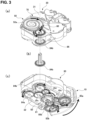
- Fig. 3(a) is a perspective view on the front surface side illustrating a state of removing the suction port cover 10 and the housing 20 from the inhaler 100
- Fig. 3(a) is a perspective view of the back side in the same state.
- Fig. 3(a) mainly illustrates the counter mechanism
- FIG. 3(b) illustrates a conjunction mechanism for causing the counter mechanism to coordinate with the operation of the suction port cover 10. Additionally, Fig. 4 extracts and schematically illustrates respective elements for clear illustration of operations of the respective elements constituting the counter mechanism.
- Fig. 4(a) mainly illustrates the front surface side of the counter mechanism, and Fig. 4(b) mainly transparently illustrates the back side of the counter mechanism.
- the counter mechanism includes a counter dial 50 and a pinion gear 60 as main components. Additionally, the counter mechanism includes a slide lane 70 as a preferred element. In this embodiment, the elements 50, 60, 70 constituting the counter mechanism are disposed on the upper lid 31 side of the casing 30, specifically, between the upper lid 31 of the casing 30 and the top cover 21 of the housing 20.
- the counter dial 50 is a disk-shaped member, has a front surface 51 on which information presenting means, such as numbers, characters, drawings, colors, or signs indicating the number of remaining drugs 51a, are aligned in a spiral pattern and represented, and a back surface 52 on which a rack gear 52a in a spiral pattern is formed corresponding to the alignment of the information presenting means.
- information presenting means such as numbers, characters, drawings, colors, or signs indicating the number of remaining drugs 51a
- a back surface 52 on which a rack gear 52a in a spiral pattern is formed corresponding to the alignment of the information presenting means.
- the maximum number of usages of the drug is "30”
- the number "0" (zero) is represented in the proximity of the center of the front surface 51 of the counter dial 50
- the numbers from"0" to "30” are aligned and represented from there so as to extend in a spiral pattern in the outer peripheral direction.
- the counter mechanism first presents "30" as the maximum number of usages of the drug to the user, and each time opening and closing of the suction port cover 10 are repeated, the number of remaining drugs presented by the counter mechanism is counted down to "0."
- the number "30" corresponding to the maximum number of usages can be represented in the proximity of the center of the counter dial 50, and the numbers from “30” to “0” can be aligned and represented from there so as to extend in a spiral pattern in the outer peripheral direction.
- the number of remains is counted up from "0" to "30.”
- the rack gear 52a in the spiral pattern is formed corresponding to the above-described row of the numbers on the back surface 52 of the counter dial 50. Specifically, when it is assumed that the numbers are connected with an imaginary line in the ascending order or the descending order, the rack gear 52a in the spiral pattern same as the spiral formed by the imaginary line is formed immediately below the imaginary line.
- the pinion gear 60 is a circular gear having a small bore fitted to the rack gear 52a formed on the back surface 52 of the counter dial 50.
- the pinion gear 60 is in conjunction with the suction port cover 10 by a conjunction mechanism described later, and turns in a constant direction in conjunction with the open/close operation of the suction port cover 10.
- the position of the pinion gear 60 itself is fixed in the inhaler 100, and although the pinion gear 60 turns in the constant direction with a rotation shaft as the center, the position of the rotation shaft does not change by the turning.
- the position of the counter dial 50 varies along the rack gear 52a.
- the variation direction of the position of the counter dial 50 is preferably restricted by the slide lane 70.
- the slide lane 70 is an element for restricting the movement direction of the counter dial 50 in the constant direction.
- the slide lane 70 is disposed on the upper lid 31 of the casing 30.
- the slide lane 70 is disposed at a position abutting on the outer peripheral edge of the counter dial 50.
- the counter dial 50 gradually moves in the direction of extending the slide lane 70 while sliding along the slide lane 70.
- the extending direction of the slide lane 70 only needs to be appropriately designed considering a space before and after the movement of the counter dial 50.
- the position of the window portion 21a formed in the top cover 21 of the housing 20 is immovable.
- the window portion 21a is preferably disposed immediately above the pinion gear 60.
- the window portion 21a can be disposed not limited to be immediately above the pinion gear 60.
- Fig. 4(a) and Fig. 4(b) schematically illustrate a state in which the relative positional relationship between the counter dial 50, the pinion gear 60, the slide lane 70, and the window portion 21a varies in accordance with the movement of the counter dial 50. From these drawings, a state in which the counter dial 50 moves in the constant direction while rotating along the slide lane 70 to count down the number of remaining drugs 51a by one visually perceived through the window portion 21a can be seen.
- the conjunction mechanism is configured by including a hub gear 81, a ratchet gear 82, two index wheels 83a, 83b, two base spools 84a, 84b, four idler gears 85a to 85d, and a relay gear 86.
- the suction port cover 10 when the suction port cover 10 is caused to transition from the closed state to the open state, the suction port cover 10 turns in the direction indicated by the arrow with a turning fulcrum as the center.
- the turning fulcrum of the suction port cover 10 is joined to the hub gear 81 disposed in the proximity of the center on the bottom lid 32 side of the casing 30.
- the hub gear 81 When the suction port cover 10 is turned at a constant angle, the hub gear 81 also turns at the same angle in the same direction as those of the suction port cover 10.
- the hub gear 81 is joined to the ratchet gear 82, and the ratchet gear 82 is fitted to the two idler gears (the first idler gear 85a and the third idler gear 85c).
- the ratchet gear 82 is configured so as to transmit the rotational motion in the constant direction of the hub gear 81 to the first and third idler gears 85a, 85c, but to idle to the two idler gears 85a, 85c and not to transmit the motion in the rotational motion in the opposite direction.
- the rotational motion of the hub gear 81 is transmitted to the first and third idler gears 85a, 85c via the ratchet gear 82.
- the rotational motion of the hub gear 81 is not transmitted to the two idler gears 85a, 85c.
- the ratchet gear 82 joined to the hub gear 81 is first coupled to the first index wheel 83a via the first idler gear 85a. That is, the rotational motion is transmitted in the order of the ratchet gear 82, the first idler gear 85a, and the first index wheel 83a. In view of this, while the first idler gear 85a turns in the opposite direction to the hub gear 81, the first index wheel 83a turns in the same direction as the hub gear 81. Additionally, the first idler gear 85a is coupled to the second index wheel 83b via the second idler gear 85b.
- the rotational motion is transmitted in the order of the ratchet gear 82, the first idler gear 85a, the second idler gear 85b, and the second index wheel 83b.
- the second idler gear 85b turns in the same direction as the hub gear 81
- the first idler gear 85a and the second index wheel 83b turn in the opposite direction to the hub gear 81.
- the two index wheels 83a, 83b turn in the directions opposite to one another.
- the index wheels 83a, 83b play a role in tearing off the backing sheet 220 from the blister strip 200.
- the rotation shafts of the respective index wheels 83a, 83b are engaged with the proximity of the starting end portion of the backing sheet 220 (or the base portion sheet 210) of the blister strips 200 in the casing 30.
- Turning the index wheels 83a, 83b provides tensile force for separating the backing sheet 220 from the base portion sheet 210 to the blister strip 200.
- the peeling mechanism is configured such that, by tearing off the backing sheet 220 from the two blister strips 200 approximately simultaneously by the two index wheels 83a, 83b, the drugs taken out from the blister strips 200 are mixed in the manifold 42.
- the ratchet gear 82 joined to the hub gear 81 is also coupled to the first base spool 84a via the third idler gear 85c. That is, the rotational motion is transmitted in the order from the ratchet gear 82, the third idler gear 85c, and the first base spool 84a.
- the third idler gear 85c turns in the opposite direction to the hub gear 81
- the first base spool 84a turns in the same direction as the hub gear 81.
- the third idler gear 85c is coupled to the second base spool 84b via the fourth idler gear 85d.
- the rotational motion is transmitted in the order from the ratchet gear 82, the third idler gear 85c, the fourth idler gear 85d, and the second base spool 84b.
- the fourth idler gear 85d turns in the same direction as the hub gear 81
- the third idler gear 85c and the second base spool 84b turn in the opposite direction to the hub gear 81.
- the two base spools 84a, 84b turn in the directions opposite to one another.
- the base spools 84a, 84b play a role in letting out the blister strip 200 toward the index wheels 83a, 83b side described above.
- the rotation shafts of the respective base spools 84a, 84b are engaged with the proximity of the terminating end portion of the blister strip 200 in the casing 30. Additionally, in the state before start of use, the long blister strip 200 is wound around the rotation shafts of the respective base spools 84a, 84b. Then, turning the base spools 84a, 84b in conjunction with the operation of opening the suction port cover 10 sends out the blister strip 200 to the index wheels 83a, 83b side.
- the proximity of the starting end portion of the backing sheet 220 of the blister strip 200 is mounted on the rotation shafts of the index wheels 83a, 83b, and the proximity of the terminating end portion of the blister strip 200 is mounted on the rotation shafts of the base spools 84a, 84b such that looseness does not occur by providing constant tensile force from the starting end portion to the terminating end portion.
- the rotation shaft of the second base spool 84b extends from the bottom lid 32 to the upper lid 31 of the casing 30 so as to penetrate in the thickness direction. Additionally, the rotation shaft of the second base spool 84b is joined to the center of the relay gear 86 disposed on the upper lid 31 side of the casing 30 to also function as the rotation shaft of the relay gear 86. Then, the relay gear 86 is fitted to the pinion gear 60 constituting the above-described counter mechanism.
- the suction port cover 10 coordinates with the counter mechanism and the peeling mechanism via the conjunction mechanism.
- the blister opening means of the present invention is not limited to this.
- a lever that can be manually raised or lowered is disposed, and the peeling mechanism can be caused to coordinate with the lever.
- the suction port cover 10 need not to be coordinated with the peeling mechanism.
- the suction port cover 10 may be opened to ensure inhaling the drug, or after the suction port cover 10 is opened, the lever may be lowered to drive the peeling mechanism to ensure inhaling the drug.
- the one coordinated with the peeling mechanism is not limited to the suction port cover 10 or the lever.
- a button type and a grip type can be employed.
- the present invention relates to an inhaler of powdered drug or a counter mechanism thereof. Accordingly, the present invention can be, for example, used in the pharmaceutical industry.
Landscapes
- Health & Medical Sciences (AREA)
- Engineering & Computer Science (AREA)
- Life Sciences & Earth Sciences (AREA)
- General Health & Medical Sciences (AREA)
- Veterinary Medicine (AREA)
- Biomedical Technology (AREA)
- Heart & Thoracic Surgery (AREA)
- Hematology (AREA)
- Anesthesiology (AREA)
- Animal Behavior & Ethology (AREA)
- Bioinformatics & Cheminformatics (AREA)
- Public Health (AREA)
- Pulmonology (AREA)
- Biophysics (AREA)
- Physics & Mathematics (AREA)
- General Physics & Mathematics (AREA)
- Theoretical Computer Science (AREA)
- Pharmacology & Pharmacy (AREA)
- Medical Preparation Storing Or Oral Administration Devices (AREA)
- Pharmaceuticals Containing Other Organic And Inorganic Compounds (AREA)
Abstract
Description
- The present invention relates to an inhaler for inhaling powdered drug individually packed in a blister strip. To describe specifically, the present invention includes a counter mechanism for presenting the number of remaining uses of a drug to a user.
- Conventionally, for example, there has been known an inhaler for causing a patient to inhale a drug to suppress an inflammation of, for example, a respiratory tract, and accelerate extension of a bronchus (for example, Patent Documents 1 to 4). Since the drug inhaler is to directly administrate powdered drug to a respiratory tract and a lung as an inflamed affected part using inspiratory force of a patient himself/herself, there are advantageous in that even a small amount of drug can be concentratedly applied over the affected part, generation of a side effect can be inhibited, and expression of an effect quickens.
- A general inhale device is accommodated with one or a plurality of blister strips wound in a whirl shape. As illustrated in
Fig. 5 , a strip-shaped blister strip 200 in which drugs are sealed is configured by bonding mutual inner surfaces of a longbase portion sheet 210 and abacking sheet 220. Additionally, thebase portion sheet 210 includes a plurality ofblisters 211 forming spaces to seal the drugs at constant intervals in its longitudinal direction. Each of theblisters 211 contains the desired drug by an amount appropriate for one administration. At the administration, thebacking sheet 220 is gradually torn off from thebase portion sheet 210 such that the appropriate amount of drugs are exposed. Note that theblister strip 200 in the inhaler seals a drug for a respiratory disease treatment, such as asthma, chronic obstructive pulmonary disease (COPD), bronchitis, or chest infection. Note that it is only necessary to use the publicly known drug. Especially,Patent Document 2 discloses an inhaler that allows taking out drugs from two respective blister strips and mixing the drugs in a manifold. - Additionally,
Patent Document 2 toPatent Document 4 disclose a counter mechanism for presenting the number of remaining drugs. The counter mechanism is in conjunction with a cover for opening and closing a suction port and a peeling mechanism for tearing off a backing sheet from a blister strip. Specifically, when the suction port cover is opened, the backing sheet is partially torn off from the blister strip by the peeling mechanism, and a drug by one dose amount is taken out from the blister strip. Then, simultaneously with this, the number of remains presented by the counter mechanism decreases by one. - Patent Document 1:
JP-T-2004-512147 - Patent Document 2:
JP-T-2009-502287 - Patent Document 3:
JP-T-2007-526562 - Patent Document 4:
JP-A-2014-113260 - For example, the counter mechanism disclosed in
Patent Document 3 indicates ones place and tens place by different dials. That is, when the dial indicating the ones place rotates by one, the dial indicating the tens place is turned by a predetermined angle to carry the number indicated by the tens place by one. However, when the number of remains of two digits is presented by the two dials, there are problems that the structure of the counter mechanism is complicated and this inhibits downsizing of the inhaler. Additionally, a problem that when a failure occurs in any one of the ones place dial and the tens place dial, the number of remains cannot be accurately presented is conceivable. Especially, while the inhaler handles a fine powdered drug, when the number of dials or gears constituting the counter mechanism increases, microparticles of the drug are interposed between the respective dials and gears, and it is concerned that a failure that the counter mechanism fails to appropriately function occurs. - In contrast to this, for example, as shown in
Patent Document 4, to simplify the structure of the counter mechanism, the number of remains of two or more digits can be represented in the proximity of an outer periphery of one dial. However, in the case, as the number of remains that should be represented increases, the diameter of the dial becomes large. As a result, a problem that the entire size of the inhaler increases and this greatly limits the design layout of the inhaler arises. - Therefore, a main object of the present invention is to provide a counter mechanism having a simple and compact configuration.
- As a result of serious examination of the solution for the problems accompanied by the conventional invention by the inventor of the present invention, knowledge that representation of information displaying the number of remaining drugs or the like in a spiral pattern on a disc-shaped dial allows presenting the large number of remains even with one dial having a small diameter has been obtained. Then, it has been conceived that, by disposing a mechanism to turn the dial according to, for example, an operation of blister opening means including a suction port cover, a lever, or the like, the simple and compact counter mechanism can be achieved, thus completing the present invention. To describe specifically, the present invention has the following configurations.
- A first aspect of the present invention relates to an inhaler of powdered drug. The inhaler according to the present invention includes blister opening means that tears off a backing sheet from a blister strip to open a blister. The blister opening means, for example, may tear off the backing sheet from the blister strip in conjunction with an open/close operation of a suction port cover that opens and closes a suction port, or may tear off the backing sheet from the blister strip in conjunction with a raise and lower operation of a lever disposed separately from the suction port cover. Thus, the inhaler gradually tears off the backing sheet from one or a plurality of the blister strips by the blister opening means and sequentially supplies powdered drug by one dose amount to a space configured to inhale through the suction port. That is, the inhaler of the present invention may take out the drug by one dose amount from one blister strip, or may take out the drugs from the two or more respective blister strips and mix them to prepare one dose amount. Additionally, the inhaler according to the present invention includes a counter mechanism for presenting the number of remaining drugs individually packed by the blister strip in conjunction with the operation of the blister opening means. Note that "the number of remains" may be indicated by a countdown method that gradually decreases the number of remains to 0, or may be indicated by a count up method that gradually increases the number of remains from 0. Even with the count up method, the number of drugs is obviously limited and the maximum number is determined. Therefore, when the maximum number is preliminarily notified to a user, the number of remaining drugs can be presented to the user. Note that when the number of remaining blisters becomes 0, a counter dial may be disabled to rotate any further to stop a drive system.
- The counter mechanism of the inhaler includes the counter dial and a pinion gear. The counter dial has a disk shape, and has a back surface side on which the rack gear in a spiral pattern is formed and a front surface side on which information displaying the number of remaining drugs are aligned in a spiral pattern and represented along the rack gear. Note that as the "information displaying the number of remaining drugs," information presenting means, such as number, a character, a drawing, a color, or a sign, only needs to be represented on the front surface of the counter dial by the publicly known representation method, such as printing or marking. The pinion gear is fitted to the rack gear and turns in a constant direction in conjunction with the operation of the blister opening means. Although a rotation shaft of the pinion gear is fixed and a position of the pinion gear is immovable, turning the pinion gear moves the counter dial. Thus, among a plurality of pieces of the information displaying the number of remains represented on the counter dial, the information that has reached a specific position (for example, immediately above the rotation shaft of the pinion gear) being the actual number of remains can be presented. Thus, in the present invention, the large number of numbers or the like is aligned in the spiral pattern and represented on the counter dial. Therefore, for example, even when the number of remains of two or more digits is presented, the number or the like can be consolidated to one counter dial having a small diameter to be represented. Since this eliminates the need for disposing two counter dials or disposing a dial having a large diameter to present the number of remains of two or more digits as in the prior art, simplification and downsizing of the structure of the counter mechanism can be achieved.
- In the inhaler according to the present invention, a housing of the inhaler preferably includes a window portion for visually perceiving one piece of the information displaying the number of remaining drugs represented on the counter dial from outside the housing. This allows presenting the number of remaining drugs in an aspect of easily understood by the user.
- In the inhaler according to the present invention, the counter mechanism preferably further includes a slide lane that restricts a movement direction of the counter dial to a constant direction when the pinion gear turns. Thus, by disposing the slide lane to restrict the movement direction of the counter dial, the number of remains can be stably presented and a blank space prepared in advance for movement of the counter dial can be minimized.
- A second aspect of the present invention relates to the counter mechanism. The counter mechanism according to the second aspect of the present invention can be widely used as means to present any number of uses, in addition to the counter mechanism for the inhaler. To describe specifically, the counter mechanism includes a counter dial and a pinion gear. The counter dial has a back surface side on which a rack gear in a spiral pattern is formed and a front surface side on which information displaying the number of usages is aligned in a spiral pattern and represented along the rack gear. The pinion gear is fitted to the rack gear and turns in a constant direction in conjunction with a use operation.
- With the present invention, the counter mechanism having the simple and compact configuration can be provided.
-
-
Fig. 1 is a perspective view illustrating an inhaler of one embodiment according to the present invention from a front surface side. -
Fig. 2 illustrates a state in which a suction port cover and a top cover are removed from the inhaler illustrated inFig. 1 . -
Fig. 3 illustrates an example of an internal structure around a counter mechanism of the inhaler of one embodiment according to the present invention. -
Fig. 4 schematically illustrates a structure of the counter mechanism of one embodiment according to the present invention. -
Fig. 5 illustrates an outline of a blister strip accommodated in the inhaler. - The following describes configurations to carry out the present invention using the drawings. The present invention is not limited to the configurations described below, but includes those appropriately changed from the configurations below by a person skilled in the art within an obvious range.
-
Fig. 1 illustrates aninhaler 100 of one embodiment according to the present invention. Two blister strips 200 (seeFig. 5 ) are accommodated inside ahousing 20 of theinhaler 100 illustrated inFig. 1 . In theinhaler 100, opening a suction port cover 10 mounted on thehousing 20 exposes a suction port of a drug. Additionally, an open/close operation of thesuction port cover 10 is in conjunction with a peeling mechanism inside thehousing 20. Thus, in this embodiment, the blister opening means is configured by thesuction port cover 10 and the peeling mechanism. Opening the suction port cover 10 partially tears off thebacking sheet 220 of the twoblister strips 200 by the peeling mechanism, and the powdered drug taken out from ablister 211 of thebase portion sheet 210 is supplied to a manifold and is mixed inside of the manifold. The mixed drug can be inhaled through the suction port. The peeling mechanism in conjunction with thesuction port cover 10 is already publicly known as described in, for example, Patent Document 1 toPatent Document 4, and various kinds of peeling mechanisms publicly-known at the time of application can be appropriately employed also in theinhaler 100 according to the present invention. In view of this, Description of this application omits the illustration and description of details of the peeling mechanism of theblister strip 200. - Additionally, as illustrated in
Fig. 1 , thehousing 20 is configured by combining atop cover 21 and abottom cover 22 and forms an accommodation space of theblister strip 200 and another internal mechanism. Thetop cover 21 is a cover member covering the front surface side of theinhaler 100, and awindow portion 21a penetrating the cover in a thickness direction is formed in a part of thetop cover 21. A user can visually check the number of remaining drugs presented by the counter mechanism accommodated in thehousing 20 through thewindow portion 21a of the top cover 21 (in the example illustrated inFig. 1 , it is presented that the number of remaining drugs is "30"). The counter mechanism is in conjunction with the above-described suction port cover 10 or peeling mechanism. When the suction port cover 10 in the close state is opened, the number of remains presented by the counter mechanism is counted down (or counted up) by one. The present invention features in the counter mechanism presenting the number of remaining drugs or the like. Therefore, the following will describe the specific content of the present invention, mainly the counter mechanism, in detail. -
Fig. 2 illustrates a state in which thesuction port cover 10 and thetop cover 21 are removed from theinhaler 100 illustrated inFig. 1 . As illustrated inFig. 2 , thehousing 20 internally includes acasing 30 mainly accommodating the twoblister strips 200 and the peeling mechanism thereof, and amouthpiece 40 including asuction port 41 communicating with a manifold 42 is disposed on the inhale side of thecasing 30. Note that anupper lid 31 positioned on thetop cover 21 side and abottom lid 32 positioned on thebottom cover 22 side are combined to configure thecasing 30. In theinhaler 100 of the present invention, opening thesuction port cover 10 exposes themouthpiece 40 in which thesuction port 41 is formed. The user breathes in while taking themouthpiece 40 into his/her mouth to ensure inhaling the two kinds of drugs mixed in the manifold 42 through thesuction port 41. Note that themouthpiece 40 and the manifold 42 can be different components or can be an integrated component. - Next, as illustrated in
Fig. 2 to Fig. 4 , theinhaler 100 includes the counter mechanism for presenting the number of remaining drugs to the user. Similarly to the peeling mechanism, the counter mechanism is in conjunction with opening and closing thesuction port cover 10. By causing the suction port cover 10 to transition from the closed state to the open state, the number of remaining drugs is counted down (or counted up).Fig. 3(a) is a perspective view on the front surface side illustrating a state of removing thesuction port cover 10 and thehousing 20 from theinhaler 100, andFig. 3(a) is a perspective view of the back side in the same state.Fig. 3(a) mainly illustrates the counter mechanism, andFig. 3(b) illustrates a conjunction mechanism for causing the counter mechanism to coordinate with the operation of thesuction port cover 10. Additionally,Fig. 4 extracts and schematically illustrates respective elements for clear illustration of operations of the respective elements constituting the counter mechanism.Fig. 4(a) mainly illustrates the front surface side of the counter mechanism, andFig. 4(b) mainly transparently illustrates the back side of the counter mechanism. - As illustrated in each drawing, the counter mechanism includes a
counter dial 50 and apinion gear 60 as main components. Additionally, the counter mechanism includes aslide lane 70 as a preferred element. In this embodiment, theelements upper lid 31 side of thecasing 30, specifically, between theupper lid 31 of thecasing 30 and thetop cover 21 of thehousing 20. - The
counter dial 50 is a disk-shaped member, has afront surface 51 on which information presenting means, such as numbers, characters, drawings, colors, or signs indicating the number of remainingdrugs 51a, are aligned in a spiral pattern and represented, and aback surface 52 on which arack gear 52a in a spiral pattern is formed corresponding to the alignment of the information presenting means. In the example illustrated inFig. 4 , the maximum number of usages of the drug is "30," the number "0" (zero) is represented in the proximity of the center of thefront surface 51 of thecounter dial 50, and the numbers from"0" to "30" are aligned and represented from there so as to extend in a spiral pattern in the outer peripheral direction. In this case, the counter mechanism first presents "30" as the maximum number of usages of the drug to the user, and each time opening and closing of thesuction port cover 10 are repeated, the number of remaining drugs presented by the counter mechanism is counted down to "0." On the contrary, the number "30" corresponding to the maximum number of usages can be represented in the proximity of the center of thecounter dial 50, and the numbers from "30" to "0" can be aligned and represented from there so as to extend in a spiral pattern in the outer peripheral direction. In this case, the number of remains is counted up from "0" to "30." Additionally, therack gear 52a in the spiral pattern is formed corresponding to the above-described row of the numbers on theback surface 52 of thecounter dial 50. Specifically, when it is assumed that the numbers are connected with an imaginary line in the ascending order or the descending order, therack gear 52a in the spiral pattern same as the spiral formed by the imaginary line is formed immediately below the imaginary line. - The
pinion gear 60 is a circular gear having a small bore fitted to therack gear 52a formed on theback surface 52 of thecounter dial 50. Thepinion gear 60 is in conjunction with thesuction port cover 10 by a conjunction mechanism described later, and turns in a constant direction in conjunction with the open/close operation of thesuction port cover 10. Thus, by fitting thepinion gear 60 and therack gear 52a in the spiral pattern, the rotational motion of thepinion gear 60 is transformed into a linear motion along therack gear 52a in the spiral pattern. The position of thepinion gear 60 itself is fixed in theinhaler 100, and although thepinion gear 60 turns in the constant direction with a rotation shaft as the center, the position of the rotation shaft does not change by the turning. On the other hand, in accordance with the turning of the fixedpinion gear 60, the position of thecounter dial 50 varies along therack gear 52a. The variation direction of the position of thecounter dial 50 is preferably restricted by theslide lane 70. - The
slide lane 70 is an element for restricting the movement direction of thecounter dial 50 in the constant direction. In this embodiment, theslide lane 70 is disposed on theupper lid 31 of thecasing 30. Theslide lane 70 is disposed at a position abutting on the outer peripheral edge of thecounter dial 50. In view of this, when thecounter dial 50 starts moving in accordance with the turning of thepinion gear 60, thecounter dial 50 gradually moves in the direction of extending theslide lane 70 while sliding along theslide lane 70. The extending direction of theslide lane 70 only needs to be appropriately designed considering a space before and after the movement of thecounter dial 50. - As illustrated in
Fig. 4(a) , the position of thewindow portion 21a formed in thetop cover 21 of thehousing 20 is immovable. For example, as illustrated inFig. 4 , thewindow portion 21a is preferably disposed immediately above thepinion gear 60. However, as long as thewindow portion 21a is at the position overlapping with thecounter dial 50 through before and after the movement of thecounter dial 50 and at the position overlapping on the imaginary line in the spiral pattern connecting the numbers of remainingdrugs 51a represented on thecounter dial 50, thewindow portion 21a can be disposed not limited to be immediately above thepinion gear 60. Thus, since the position of thewindow portion 21a is immovable, when thecounter dial 50 moves in the constant direction in accordance with the turning of thepinion gear 60, the number ofremains 51a that can be visually perceived through thewindow portion 21a changes. Specifically,Fig. 4(a) and Fig. 4(b) schematically illustrate a state in which the relative positional relationship between thecounter dial 50, thepinion gear 60, theslide lane 70, and thewindow portion 21a varies in accordance with the movement of thecounter dial 50. From these drawings, a state in which thecounter dial 50 moves in the constant direction while rotating along theslide lane 70 to count down the number of remainingdrugs 51a by one visually perceived through thewindow portion 21a can be seen. - Subsequently, with reference to
Fig. 3 , the conjunction mechanism that causes thesuction port cover 10 and the above-described counter mechanism to coordinate will be described in detail. Note that the conjunction mechanism illustrated inFig. 3 also plays a role in causing the peeling mechanism of the two blister strips and the suction port cover 10 to coordinate at the same time. The conjunction mechanism is configured by including ahub gear 81, aratchet gear 82, twoindex wheels base spools idler gears 85a to 85d, and arelay gear 86. - First, as illustrated in
Fig. 3(b) , when thesuction port cover 10 is caused to transition from the closed state to the open state, the suction port cover 10 turns in the direction indicated by the arrow with a turning fulcrum as the center. The turning fulcrum of thesuction port cover 10 is joined to thehub gear 81 disposed in the proximity of the center on thebottom lid 32 side of thecasing 30. When thesuction port cover 10 is turned at a constant angle, thehub gear 81 also turns at the same angle in the same direction as those of thesuction port cover 10. Thehub gear 81 is joined to theratchet gear 82, and theratchet gear 82 is fitted to the two idler gears (thefirst idler gear 85a and thethird idler gear 85c). Theratchet gear 82 is configured so as to transmit the rotational motion in the constant direction of thehub gear 81 to the first and third idler gears 85a, 85c, but to idle to the twoidler gears hub gear 81 is transmitted to the first and third idler gears 85a, 85c via theratchet gear 82. To cause the suction port cover 10 to transition from the open state to the closed state, the rotational motion of thehub gear 81 is not transmitted to the twoidler gears - The
ratchet gear 82 joined to thehub gear 81 is first coupled to thefirst index wheel 83a via thefirst idler gear 85a. That is, the rotational motion is transmitted in the order of theratchet gear 82, thefirst idler gear 85a, and thefirst index wheel 83a. In view of this, while thefirst idler gear 85a turns in the opposite direction to thehub gear 81, thefirst index wheel 83a turns in the same direction as thehub gear 81. Additionally, thefirst idler gear 85a is coupled to thesecond index wheel 83b via thesecond idler gear 85b. That is, the rotational motion is transmitted in the order of theratchet gear 82, thefirst idler gear 85a, thesecond idler gear 85b, and thesecond index wheel 83b. In view of this, while thesecond idler gear 85b turns in the same direction as thehub gear 81, thefirst idler gear 85a and thesecond index wheel 83b turn in the opposite direction to thehub gear 81. Thus, in conjunction with the operation of opening thesuction port cover 10, the twoindex wheels - The
index wheels backing sheet 220 from theblister strip 200. The rotation shafts of therespective index wheels casing 30. Turning theindex wheels backing sheet 220 from thebase portion sheet 210 to theblister strip 200. The peeling mechanism is configured such that, by tearing off thebacking sheet 220 from the twoblister strips 200 approximately simultaneously by the twoindex wheels manifold 42. - On the other hand, the
ratchet gear 82 joined to thehub gear 81 is also coupled to thefirst base spool 84a via thethird idler gear 85c. That is, the rotational motion is transmitted in the order from theratchet gear 82, thethird idler gear 85c, and thefirst base spool 84a. In view of this, while thethird idler gear 85c turns in the opposite direction to thehub gear 81, thefirst base spool 84a turns in the same direction as thehub gear 81. Thethird idler gear 85c is coupled to thesecond base spool 84b via thefourth idler gear 85d. That is, the rotational motion is transmitted in the order from theratchet gear 82, thethird idler gear 85c, thefourth idler gear 85d, and thesecond base spool 84b. In view of this, while thefourth idler gear 85d turns in the same direction as thehub gear 81, thethird idler gear 85c and thesecond base spool 84b turn in the opposite direction to thehub gear 81. Thus, in conjunction with the operation of opening thesuction port cover 10, the twobase spools - The base spools 84a, 84b play a role in letting out the
blister strip 200 toward theindex wheels respective base spools blister strip 200 in thecasing 30. Additionally, in the state before start of use, thelong blister strip 200 is wound around the rotation shafts of therespective base spools suction port cover 10 sends out theblister strip 200 to theindex wheels backing sheet 220 of theblister strip 200 is mounted on the rotation shafts of theindex wheels blister strip 200 is mounted on the rotation shafts of the base spools 84a, 84b such that looseness does not occur by providing constant tensile force from the starting end portion to the terminating end portion. - Additionally, as illustrated in
Fig. 3 , in this embodiment, the rotation shaft of thesecond base spool 84b extends from thebottom lid 32 to theupper lid 31 of thecasing 30 so as to penetrate in the thickness direction. Additionally, the rotation shaft of thesecond base spool 84b is joined to the center of therelay gear 86 disposed on theupper lid 31 side of thecasing 30 to also function as the rotation shaft of therelay gear 86. Then, therelay gear 86 is fitted to thepinion gear 60 constituting the above-described counter mechanism. In view of this, when thesecond base spool 84b turns in accordance with the operation of opening thesuction port cover 10, in conjunction with this, the turning motion is transmitted in the order of therelay gear 86, thepinion gear 60, and thecounter dial 50. Note that in the illustrated embodiment, thesecond base spool 84b and therelay gear 86 are connected, but thefirst base spool 84a and therelay gear 86 can be connected. Thus, in theinhaler 100 according to this embodiment, the suction port cover 10 coordinates with the counter mechanism and the peeling mechanism via the conjunction mechanism. Note that in this embodiment, it is adjusted that the operation of opening the suction port cover 10 once counts down (or counts up) the representation of the number of remains of thecounter dial 50 that can be visually perceived through thewindow portion 21a by one. This is easily achievable by appropriately adjusting the size of the gear and the interval of the number of remains represented on thecounter dial 50. - Note that in the above-described embodiments, an example in which the
suction port cover 10 is in conjunction with the peeling mechanism and this configures the blister opening means has been described, but the blister opening means of the present invention is not limited to this. For example, separately from thesuction port cover 10, a lever that can be manually raised or lowered is disposed, and the peeling mechanism can be caused to coordinate with the lever. In this case, the suction port cover 10 need not to be coordinated with the peeling mechanism. For how to use, after the lever is lowered to drive the peeling mechanism, thesuction port cover 10 may be opened to ensure inhaling the drug, or after thesuction port cover 10 is opened, the lever may be lowered to drive the peeling mechanism to ensure inhaling the drug. Besides, the one coordinated with the peeling mechanism is not limited to the suction port cover 10 or the lever. In addition to them, a button type and a grip type can be employed. - In Description of this application, the embodiments of the present invention have been described by referring to the drawings to express the contents of the present invention. However, the present invention is not limited to the embodiments described above, but includes changed configurations and improved configurations obvious to those skilled in the art based on the matters described in Description of this application.
- The present invention relates to an inhaler of powdered drug or a counter mechanism thereof. Accordingly, the present invention can be, for example, used in the pharmaceutical industry.
DESCRIPTION OF REFERENCE SIGNS 10 suction port cover 20 housing 21 top cover 21a window portion 22 bottom cover 30 casing 31 upper lid 32 bottom lid 40 mouthpiece 41 suction port 42 manifold 50 counter dial 51 front surface 51a the number of remains 52 back surface 52a rack gear 60 pinion gear 70 slide lane 81 hub gear 82 ratchet gear 83a, 83b index wheel 84a, 84b base spool 85a to 85d idler gear 86 relay gear 100 inhaler 200 blister strip 210 base portion sheet 211 blister 220 backing sheet
Claims (4)
- An inhaler for gradually tearing off a backing sheet from one or a plurality of blister strips by blister opening means and sequentially supplying powdered drug by one dose amount to a space configured to inhale through a suction port, the inhaler comprising:a counter mechanism for presenting a number of remaining drugs individually packed by the blister strip in conjunction with an operation of the blister opening means, whereinthe counter mechanism includes:a counter dial having a back surface side on which a rack gear in a spiral pattern is formed and a front surface side on which information displaying the number of remaining drugs is aligned in a spiral pattern and represented along the rack gear; anda pinion gear fitted to the rack gear and turning in a constant direction in conjunction with the operation of the blister opening means.
- The inhaler according to claim 1, wherein a housing of the inhaler includes a window portion for visually perceiving one piece of the information displaying the number of remaining drugs represented on the counter dial from outside the housing.
- The inhaler according to claim 1, wherein the counter mechanism further includes a slide lane that restricts a movement direction of the counter dial to a constant direction when the pinion gear turns.
- A counter mechanism comprising:a counter dial having a back surface side on which a rack gear in a spiral pattern is formed and a front surface side on which information displaying a number of usages is aligned in a spiral pattern and represented along the rack gear; anda pinion gear fitted to the rack gear and turning in a constant direction in conjunction with a use operation.
Applications Claiming Priority (2)
| Application Number | Priority Date | Filing Date | Title |
|---|---|---|---|
| JP2020192801A JP6901180B1 (en) | 2020-11-19 | 2020-11-19 | Drug inhaler and counter mechanism |
| PCT/JP2021/037783 WO2022107502A1 (en) | 2020-11-19 | 2021-10-12 | Drug inhaler and counter mechanism |
Publications (4)
| Publication Number | Publication Date |
|---|---|
| EP4249021A1 true EP4249021A1 (en) | 2023-09-27 |
| EP4249021A4 EP4249021A4 (en) | 2024-09-25 |
| EP4249021B1 EP4249021B1 (en) | 2025-12-03 |
| EP4249021C0 EP4249021C0 (en) | 2025-12-03 |
Family
ID=76753079
Family Applications (1)
| Application Number | Title | Priority Date | Filing Date |
|---|---|---|---|
| EP21894376.9A Active EP4249021B1 (en) | 2020-11-19 | 2021-10-12 | Counter mechanism and drug inhaler therewith |
Country Status (7)
| Country | Link |
|---|---|
| US (1) | US12582785B2 (en) |
| EP (1) | EP4249021B1 (en) |
| JP (1) | JP6901180B1 (en) |
| CN (1) | CN116507378B (en) |
| CA (1) | CA3200109A1 (en) |
| IL (1) | IL302863B2 (en) |
| WO (1) | WO2022107502A1 (en) |
Families Citing this family (3)
| Publication number | Priority date | Publication date | Assignee | Title |
|---|---|---|---|---|
| USD1065507S1 (en) * | 2020-02-18 | 2025-03-04 | Alfred Von Schuckmann | Inhaler |
| USD1067421S1 (en) * | 2021-12-17 | 2025-03-18 | Sandoz Ag | Inhaler |
| CN119158126B (en) * | 2024-10-28 | 2025-04-01 | 浩英生物科技(苏州)有限公司 | An inhaler with metering monitoring function |
Family Cites Families (19)
| Publication number | Priority date | Publication date | Assignee | Title |
|---|---|---|---|---|
| GB1282871A (en) * | 1968-08-08 | 1972-07-26 | Kent Meters Ltd | Apparatus for registering operation of rotary counter wheels |
| GB1336014A (en) * | 1971-05-28 | 1973-11-07 | Mettoy Co Ltd | Counting device |
| JPH09299597A (en) * | 1996-05-20 | 1997-11-25 | Mamiya Op Co Ltd | Ball lending machine and ball lending machine |
| JP2002535048A (en) * | 1999-01-22 | 2002-10-22 | グラクソ グループ リミテッド | Inhalation device |
| GB0026647D0 (en) | 2000-10-31 | 2000-12-13 | Glaxo Group Ltd | Medicament dispenser |
| AU2003287821A1 (en) * | 2002-12-09 | 2004-06-30 | Script Innovations Inc. | Universal pill counting device |
| FR2850192B1 (en) * | 2003-01-20 | 2005-05-06 | Tebro | DOSING INDICATOR FOR FLUID PRODUCT DISPENSING DEVICE. |
| FR2857769B1 (en) * | 2003-07-18 | 2005-10-21 | Valois Sa | IMPROVED DOSAGE INDICATOR FOR FLUID PRODUCT DISPENSING DEVICE. |
| US7100530B2 (en) * | 2003-12-15 | 2006-09-05 | Trudell Medical International, Inc. | Dose indicating device |
| US8113199B2 (en) | 2004-02-16 | 2012-02-14 | Glaxo Group Limited | Counter for use with a medicament dispenser |
| GB0515584D0 (en) | 2005-07-28 | 2005-09-07 | Glaxo Group Ltd | Medicament dispenser |
| AR058290A1 (en) * | 2005-12-12 | 2008-01-30 | Glaxo Group Ltd | MEDICINAL DISPENSER |
| AU2007210177C1 (en) * | 2006-01-31 | 2012-11-01 | Oriel Therapeutics, Inc. | Dry powder inhalers having spiral travel paths, unit dose microcartridges with dry powder, related devices and methods |
| CA2839044C (en) * | 2009-07-30 | 2016-07-26 | Ivax International B.V. | Dose counter for a metered-dose inhaler |
| JP2013523375A (en) * | 2010-04-13 | 2013-06-17 | ビルギチ,マフムト | Mouthpiece button of dry powder inhaler |
| ES2773375T3 (en) * | 2011-03-21 | 2020-07-10 | Simplified Solutions Sweden Ab | Powder substance inhaler |
| JP5350530B1 (en) * | 2012-12-07 | 2013-11-27 | ニップファーマ株式会社 | Drug inhalation device |
| EP3042681A4 (en) * | 2013-09-02 | 2017-05-17 | Daiwa Can Company | Inhaler |
| JP2015188513A (en) * | 2014-03-27 | 2015-11-02 | 大和製罐株式会社 | inhaler |
-
2020
- 2020-11-19 JP JP2020192801A patent/JP6901180B1/en active Active
-
2021
- 2021-10-12 CA CA3200109A patent/CA3200109A1/en active Pending
- 2021-10-12 US US18/253,216 patent/US12582785B2/en active Active
- 2021-10-12 EP EP21894376.9A patent/EP4249021B1/en active Active
- 2021-10-12 WO PCT/JP2021/037783 patent/WO2022107502A1/en not_active Ceased
- 2021-10-12 CN CN202180076985.4A patent/CN116507378B/en active Active
- 2021-10-12 IL IL302863A patent/IL302863B2/en unknown
Also Published As
| Publication number | Publication date |
|---|---|
| JP6901180B1 (en) | 2021-07-14 |
| WO2022107502A1 (en) | 2022-05-27 |
| JP2022081331A (en) | 2022-05-31 |
| IL302863A (en) | 2023-07-01 |
| US12582785B2 (en) | 2026-03-24 |
| CN116507378A (en) | 2023-07-28 |
| CN116507378B (en) | 2026-02-24 |
| CA3200109A1 (en) | 2022-05-27 |
| EP4249021B1 (en) | 2025-12-03 |
| IL302863B2 (en) | 2026-05-01 |
| IL302863B1 (en) | 2026-01-01 |
| EP4249021A4 (en) | 2024-09-25 |
| EP4249021C0 (en) | 2025-12-03 |
| US20240299679A1 (en) | 2024-09-12 |
Similar Documents
| Publication | Publication Date | Title |
|---|---|---|
| EP4249021B1 (en) | Counter mechanism and drug inhaler therewith | |
| JP5465185B2 (en) | Drug-containing dosing device having a display unit for presenting a mark to a user | |
| CN1030491C (en) | inhalation device | |
| DE60115699T2 (en) | DONATION FOR MEDICAMENT | |
| DE60214575T2 (en) | DISPOSABLE DEVICE FOR MEDICINAL PRODUCTS | |
| EP3852850B1 (en) | Dry powder inhaler | |
| US20120312714A1 (en) | Tactile and low-vision indication packaging system and apparatus | |
| US20150297841A1 (en) | Medicinal inhalation device | |
| CN107735134B (en) | Blister strip advancing mechanism | |
| KR20090120001A (en) | inspirator | |
| JP5385793B2 (en) | Metered inhaler kit | |
| EP2687253B1 (en) | Dose counter for a metered-dose inhaler | |
| US12083267B2 (en) | Inhaler | |
| RU2821394C1 (en) | Drug inhaler with dose counter mechanism | |
| EP4661942A2 (en) | Dose counter subassemblies for use in dry powder inhalers | |
| EP4284473A1 (en) | Medicament packaging | |
| EP4284474B1 (en) | Dry powder inhaler | |
| CN120053823A (en) | Compound medicine blister type dry powder inhaler |
Legal Events
| Date | Code | Title | Description |
|---|---|---|---|
| STAA | Information on the status of an ep patent application or granted ep patent |
Free format text: STATUS: THE INTERNATIONAL PUBLICATION HAS BEEN MADE |
|
| PUAI | Public reference made under article 153(3) epc to a published international application that has entered the european phase |
Free format text: ORIGINAL CODE: 0009012 |
|
| STAA | Information on the status of an ep patent application or granted ep patent |
Free format text: STATUS: REQUEST FOR EXAMINATION WAS MADE |
|
| 17P | Request for examination filed |
Effective date: 20230412 |
|
| AK | Designated contracting states |
Kind code of ref document: A1 Designated state(s): AL AT BE BG CH CY CZ DE DK EE ES FI FR GB GR HR HU IE IS IT LI LT LU LV MC MK MT NL NO PL PT RO RS SE SI SK SM TR |
|
| DAV | Request for validation of the european patent (deleted) | ||
| DAX | Request for extension of the european patent (deleted) | ||
| REG | Reference to a national code |
Ref country code: DE Ref legal event code: R079 Free format text: PREVIOUS MAIN CLASS: A61M0013000000 Ipc: A61M0015000000 Ref country code: DE Ref legal event code: R079 Ref document number: 602021043875 Country of ref document: DE Free format text: PREVIOUS MAIN CLASS: A61M0013000000 Ipc: A61M0015000000 |
|
| A4 | Supplementary search report drawn up and despatched |
Effective date: 20240826 |
|
| RIC1 | Information provided on ipc code assigned before grant |
Ipc: G01M 1/24 20060101ALI20240820BHEP Ipc: A61M 15/00 20060101AFI20240820BHEP |
|
| GRAP | Despatch of communication of intention to grant a patent |
Free format text: ORIGINAL CODE: EPIDOSNIGR1 |
|
| STAA | Information on the status of an ep patent application or granted ep patent |
Free format text: STATUS: GRANT OF PATENT IS INTENDED |
|
| RIC1 | Information provided on ipc code assigned before grant |
Ipc: G01M 1/24 20060101ALI20250507BHEP Ipc: A61M 15/00 20060101AFI20250507BHEP |
|
| INTG | Intention to grant announced |
Effective date: 20250516 |
|
| GRAS | Grant fee paid |
Free format text: ORIGINAL CODE: EPIDOSNIGR3 |
|
| GRAA | (expected) grant |
Free format text: ORIGINAL CODE: 0009210 |
|
| STAA | Information on the status of an ep patent application or granted ep patent |
Free format text: STATUS: THE PATENT HAS BEEN GRANTED |
|
| AK | Designated contracting states |
Kind code of ref document: B1 Designated state(s): AL AT BE BG CH CY CZ DE DK EE ES FI FR GB GR HR HU IE IS IT LI LT LU LV MC MK MT NL NO PL PT RO RS SE SI SK SM TR |
|
| REG | Reference to a national code |
Ref country code: CH Ref legal event code: F10 Free format text: ST27 STATUS EVENT CODE: U-0-0-F10-F00 (AS PROVIDED BY THE NATIONAL OFFICE) Effective date: 20251203 Ref country code: GB Ref legal event code: FG4D |
|
| REG | Reference to a national code |
Ref country code: CH Ref legal event code: R17 Free format text: ST27 STATUS EVENT CODE: U-0-0-R10-R17 (AS PROVIDED BY THE NATIONAL OFFICE) Effective date: 20251205 |
|
| REG | Reference to a national code |
Ref country code: DE Ref legal event code: R096 Ref document number: 602021043875 Country of ref document: DE |
|
| REG | Reference to a national code |
Ref country code: IE Ref legal event code: FG4D |
|
| U01 | Request for unitary effect filed |
Effective date: 20251210 |
|
| U07 | Unitary effect registered |
Designated state(s): AT BE BG DE DK EE FI FR IT LT LU LV MT NL PT RO SE SI Effective date: 20251217 |
|
| PG25 | Lapsed in a contracting state [announced via postgrant information from national office to epo] |
Ref country code: ES Free format text: LAPSE BECAUSE OF FAILURE TO SUBMIT A TRANSLATION OF THE DESCRIPTION OR TO PAY THE FEE WITHIN THE PRESCRIBED TIME-LIMIT Effective date: 20251203 |
|
| PG25 | Lapsed in a contracting state [announced via postgrant information from national office to epo] |
Ref country code: NO Free format text: LAPSE BECAUSE OF FAILURE TO SUBMIT A TRANSLATION OF THE DESCRIPTION OR TO PAY THE FEE WITHIN THE PRESCRIBED TIME-LIMIT Effective date: 20260303 |
|
| PG25 | Lapsed in a contracting state [announced via postgrant information from national office to epo] |
Ref country code: HR Free format text: LAPSE BECAUSE OF FAILURE TO SUBMIT A TRANSLATION OF THE DESCRIPTION OR TO PAY THE FEE WITHIN THE PRESCRIBED TIME-LIMIT Effective date: 20251203 |
|
| PG25 | Lapsed in a contracting state [announced via postgrant information from national office to epo] |
Ref country code: RS Free format text: LAPSE BECAUSE OF FAILURE TO SUBMIT A TRANSLATION OF THE DESCRIPTION OR TO PAY THE FEE WITHIN THE PRESCRIBED TIME-LIMIT Effective date: 20260303 |
|
| PG25 | Lapsed in a contracting state [announced via postgrant information from national office to epo] |
Ref country code: PL Free format text: LAPSE BECAUSE OF FAILURE TO SUBMIT A TRANSLATION OF THE DESCRIPTION OR TO PAY THE FEE WITHIN THE PRESCRIBED TIME-LIMIT Effective date: 20251203 |
|
| PG25 | Lapsed in a contracting state [announced via postgrant information from national office to epo] |
Ref country code: SM Free format text: LAPSE BECAUSE OF FAILURE TO SUBMIT A TRANSLATION OF THE DESCRIPTION OR TO PAY THE FEE WITHIN THE PRESCRIBED TIME-LIMIT Effective date: 20251203 |
|
| PG25 | Lapsed in a contracting state [announced via postgrant information from national office to epo] |
Ref country code: IS Free format text: LAPSE BECAUSE OF FAILURE TO SUBMIT A TRANSLATION OF THE DESCRIPTION OR TO PAY THE FEE WITHIN THE PRESCRIBED TIME-LIMIT Effective date: 20260403 |
|
| PG25 | Lapsed in a contracting state [announced via postgrant information from national office to epo] |
Ref country code: CZ Free format text: LAPSE BECAUSE OF FAILURE TO SUBMIT A TRANSLATION OF THE DESCRIPTION OR TO PAY THE FEE WITHIN THE PRESCRIBED TIME-LIMIT Effective date: 20251203 |
|
| PG25 | Lapsed in a contracting state [announced via postgrant information from national office to epo] |
Ref country code: SK Free format text: LAPSE BECAUSE OF FAILURE TO SUBMIT A TRANSLATION OF THE DESCRIPTION OR TO PAY THE FEE WITHIN THE PRESCRIBED TIME-LIMIT Effective date: 20251203 |