EP4248887A2 - Drill guide - Google Patents
Drill guide Download PDFInfo
- Publication number
- EP4248887A2 EP4248887A2 EP23184087.7A EP23184087A EP4248887A2 EP 4248887 A2 EP4248887 A2 EP 4248887A2 EP 23184087 A EP23184087 A EP 23184087A EP 4248887 A2 EP4248887 A2 EP 4248887A2
- Authority
- EP
- European Patent Office
- Prior art keywords
- arm
- probe
- drill guide
- guide
- drill
- Prior art date
- Legal status (The legal status is an assumption and is not a legal conclusion. Google has not performed a legal analysis and makes no representation as to the accuracy of the status listed.)
- Pending
Links
Images



Classifications
-
- A—HUMAN NECESSITIES
- A61—MEDICAL OR VETERINARY SCIENCE; HYGIENE
- A61B—DIAGNOSIS; SURGERY; IDENTIFICATION
- A61B17/00—Surgical instruments, devices or methods
- A61B17/16—Instruments for performing osteoclasis; Drills or chisels for bones; Trepans
- A61B17/17—Guides or aligning means for drills, mills, pins or wires
- A61B17/1717—Guides or aligning means for drills, mills, pins or wires for applying intramedullary nails or pins
-
- A—HUMAN NECESSITIES
- A61—MEDICAL OR VETERINARY SCIENCE; HYGIENE
- A61B—DIAGNOSIS; SURGERY; IDENTIFICATION
- A61B17/00—Surgical instruments, devices or methods
- A61B17/16—Instruments for performing osteoclasis; Drills or chisels for bones; Trepans
- A61B17/17—Guides or aligning means for drills, mills, pins or wires
- A61B17/1714—Guides or aligning means for drills, mills, pins or wires for applying tendons or ligaments
-
- A—HUMAN NECESSITIES
- A61—MEDICAL OR VETERINARY SCIENCE; HYGIENE
- A61B—DIAGNOSIS; SURGERY; IDENTIFICATION
- A61B17/00—Surgical instruments, devices or methods
- A61B17/16—Instruments for performing osteoclasis; Drills or chisels for bones; Trepans
- A61B17/17—Guides or aligning means for drills, mills, pins or wires
-
- A—HUMAN NECESSITIES
- A61—MEDICAL OR VETERINARY SCIENCE; HYGIENE
- A61B—DIAGNOSIS; SURGERY; IDENTIFICATION
- A61B17/00—Surgical instruments, devices or methods
- A61B17/16—Instruments for performing osteoclasis; Drills or chisels for bones; Trepans
- A61B17/17—Guides or aligning means for drills, mills, pins or wires
- A61B17/1739—Guides or aligning means for drills, mills, pins or wires specially adapted for particular parts of the body
- A61B17/1764—Guides or aligning means for drills, mills, pins or wires specially adapted for particular parts of the body for the knee
Definitions
- the present invention is directed generally to surgical tools and instruments and, more particularly, to a multi-axis drill guide assembly for precise drilling and guidewire placement.
- a drill guide is used to line-up the drill to ensure the drilled tunnel is in the appropriate location.
- Many bone surfaces to be drilled have severe contours that vary from patient to patient. Due to the contours, it can be difficult to properly seat the drill guide against the bone. This is particularly true when the drill guide is used to assist in drilling a tibial tunnel during ACL reconstruction.
- Embodiments of the present invention are directed to a multi-axis drill guide assembly for precise drilling and guidewire placement.
- the drill guide assembly includes a guide arm having a first end and a second end with a curved slot extending from the first end toward the second end.
- the drill guide assembly also includes a curved guide extension arm having a first end and a second end. The first end of the curved guide extension arm is slidable within the curved slot of the guide arm.
- the drill guide assembly additionally has a probe arm rotatably connected to the second end of the guide arm. The probe arm is rotatable to a position that is non-planar relative to the guide arm.
- the drill guide assembly includes a guide arm having a first end and a second end with a curved slot extending from the first end toward the second end.
- the drill guide assembly also includes a curved guide extension arm having a first end and a second end. The first end of the curved guide extension arm is slidable within the curved slot of the guide arm.
- the drill guide assembly additionally has a drill guide attached to the second end of the curved guide extension arm. The drill guide extends along a first axis.
- the drill guide assembly also includes a probe arm having a first end and a second end. The first end of the probe arm is rotatably connected to the second end of the guide arm. The probe arm is rotatable toward the curved guide extension arm.
- a probe is attached to the second end of the probe arm and the probe extends along a second axis.
- the first axis In a first configuration, the first axis is at a first angle relative to the second axis and in a second configuration, the first axis is at a second angle relative to the second axis. The first angle is different from the second angle.
- the drill guide assembly includes a guide arm having a first end and a second end with a curved slot extending from the first end toward the second end.
- the drill guide assembly also includes a curved guide extension arm having a first end and a second end. The first end of the curved guide extension arm is slidable within the curved slot of the guide arm.
- the drill guide assembly additionally has a probe arm having a first end and a second end. The first end of the probe arm is rotatably connected to the second end of the guide arm. A tapered probe is attached to the second end of the probe arm.
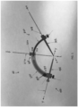
- FIG. 1 shows a side perspective view schematic representation of a drill guide assembly 100, according to an embodiment.
- the drill guide assembly 100 comprises a curved or bent guide arm 200.
- the guide arm 200 has a first end 202 connected to a probe assembly 300 and a second end 204 connected to a drill guide sub-assembly 400.
- the probe assembly 300 comprises a probe 302 extending along a longitudinal first axis x - x.
- a drill guide 408 is connected to the drill guide sub-assembly 400 and extends along a second axis y - y, which is transverse relative to the first axis x - x in the depicted embodiment.
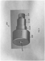
- the probe 302 comprises an elongated shaft 304 with a first end 306 and a second end 308.
- the probe 302 is tapered, decreasing in diameter from the first end 306 to the second end 308.
- the first end 306 of the probe 302 comprises a knurled cylindrical cap 310 for maintaining positioning of the probe 302, as described in detail below.
- the second end 308 of the probe 302 is rounded.
- the second end 308 of the probe 302 is spherical.
- a rounded or spherical second end 308 of the probe 302 protects any articular surfaces while advancing to the desired location in the joint.
- the rounded or spherical second end 308 comprises an outer surface 312 with a circumference.
- a spike 314 extends from the outer surface 312 of the rounded or spherical second end 308. As shown in FIG. 2 , the spike 314 extends to a point 316. The spike 314 extends at angle relative to the first axis x - x (through the probe 302). In the depicted embodiment, the spike 314 is approximately or equal to 90 degrees (i.e., substantially perpendicular) relative to the first axis x - x. The spike 314 is used to grip the bone while also providing a target for a drill pin location, as discussed below. In an embodiment, the probe 302 is cannulated such that the first end 306 and the second end 308 are open, allowing a first guidewire 318 ( FIG. 1 ) to pass through the probe 302 to further secure the position of the drill guide 408.
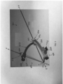
- FIG. 3 there is shown a top perspective view schematic representation of the drill guide assembly 100, according to an embodiment.
- the probe 302 is connected to the guide arm 200 via a probe arm 320.
- the probe arm 320 is curved or bent in a fashion similar to the guide arm 200.
- the probe arm 320 comprises a first end 322 and a second end 324.
- the first end 322 connects to the guide arm 200, as described in detail below.
- the second end 324 connects to the probe 302.
- the second end 324 of the probe arm 320 comprises a channel 326 extending therethrough along the first axis x - x.
- the channel 326 is sized and configured to accommodate movement of the probe 302 in and out of the channel 326.
- the cap 310 of the probe 302 functions as a stop and prevents the probe 302 from sliding entirely through the channel 326.
- the second end 324 of the probe arm 320 is cubic or otherwise rectangular. Although the second end 324 may have other geometries, the cubic or rectangular shape of the second end 324 accommodates a locking mechanism 328.
- the locking mechanism 328 is a locking screw.
- the locking screw 328 is extended into the channel 326 in the second end 324.
- the locking screw 328 is transverse to the first axis x - x.
- the locking screw 328 extends in a direction or along an axis that is substantially perpendicular to the first axis x - x.
- the locking screw 328 is tightened against the probe 302 within the channel 326.
- the first end 322 of the probe arm 320 is connected to the guide arm 200.
- the first end 322 of the probe arm 320 is rotatably attached to the guide arm 200 via a pivotable connector 206.
- the pivotable connector 206 is a pivot locking screw in the embodiment shown in FIG. 3 .
- the pivot locking screw 206 extends into the first end 202 of the guide arm 200, as shown in FIG. 1 .
- the probe arm 320 is preferably rotatable up to a total of 240 degrees about the pivot locking screw 206.
- probe arm 320 is rotatable more than a total of 240 degrees about the pivot locking screw 206 (e.g., up to and beyond 360 degrees in certain embodiments), as should be understood by a person of ordinary skill in the art in conjunction with a review of this disclosure.
- the pivot locking screw 206 comprises a first cylindrical portion 208 (with a first diameter) connected to threads 210, with one or more additional cylindrical portions 212A, 212B attached therebetween.
- the pivot locking screw 206 has the first cylindrical portion 208 with a first diameter connected to a second cylindrical portion 212A with a second diameter, the second cylindrical portion 212A connected to a third cylindrical portion 212B with a third diameter, and the third cylindrical portion 212B connected to the threads 210.
- the first diameter is larger than the second diameter
- the second diameter is larger than the third diameter
- the threads 210 have a diameter that is smaller than the third diameter.
- the first end 322 of the probe arm 320 extends around at least one of the additional cylindrical portions 212A, 212B, while the threads 210 are screwed into the guide arm 200 and a portion of the guide arm 200 extends around the first cylindrical portions 208 ( FIG. 1 ).
- the pivot locking screw 206 is cannulated, providing a channel 214 extending through the pivot locking screw 206, through the first cylindrical portion 308, additional cylindrical portions 212A, 212B, and the threads 210 for placement of a second guidewire 216 ( FIGs. 1 and 3 ).
- the second guidewire 216 extends along a third axis z - z, which is different than the first axis x - x and second axis y - y.
- the pivot locking screw 206 is used to join the probe arm 320 and the guide arm 200.
- the pivot locking screw 206 can also be used to lock the probe arm 320 in position after the desired angle has been achieved.
- the pivot locking screw 206 is passed through the first end 202 of the guide arm 200 and then through the probe arm 320.
- the pivot locking screw 206 is secured by screwing the threads 210 into the first end 202 of the drill guide arm 200. The locking action is achieved by tightening the pivot locking screw 206 in a clockwise direction, causing the guide arm 200 to compress the probe arm 320.
- FIGs. 5 and 6 show side perspective views schematic representations of the drill guide assembly 100 in a first configuration and a second configuration, respectively.
- the guide arm 200 comprises a curved or bent slot 218 extending along the length of the guide arm 200.
- the slot 218 begins at the second end 204 of the guide arm 200 and extends toward the first end 202 of the guide arm 200.
- the curved or bent slot 218 is sized and configured to slidably receive a drill guide extension arm 402 of the drill guide sub-assembly 400.
- the drill guide extension arm 402 is curved or bent to fit within the slot 218 in the drill guide arm 200.
- the drill guide extension arm 402 is free to slide within the slot 218 in the drill guide arm 200, while its second end 406 is connected to the drill guide 408.
- the guide arm 200 comprises a connector 205 (e.g., a lock screw) to secure or fix the drill guide extension arm 402 in a position within the slot 218.
- a connector 205 e.g., a lock screw
- the connector 205 extends into the second end 204 of the guide arm 200.
- the connector 205 locks the drill guide 408 at an angle relative to the second guidewire 216.
- the connector 205 locks the first axis x - x at an angle relative to the third axis z - z.
- FIG. 7 there is shown a close-up perspective view schematic representation of the drill guide 408, according to an embodiment.
- the second end 406 of the drill guide extension arm 402 is cubic or otherwise rectangular to accommodate a connector 410.
- the connector 410 is a lock screw that extends into the second end 406 of the drill guide extension arm 402 at an angle relative to the second axis y - y.
- the lock screw 410 extends in a direction or along an axis that is substantially perpendicular to the second axis y - y.
- the drill guide 408 has a tapered elongated shaft 412 connected to a cylindrical cap 414.
- the drill guide 408 is cannulated such that a drill pin 416 can be inserted through a channel 418 in the cap 414 and the elongated shaft 412.
- the drill guide 408 is cannulated to accept a .072 diameter drill pin 416 (but other sized drill pins can be used, as should be understood and appreciated by a person of ordinary skill in the art in conjunction with a review of this disclosure).
- the cap 414 has an external diameter larger than an internal diameter of the channel 418 such that the cap 414 prevents the drill guide 408 from sliding entirely through the channel 418 and into the surgical site.
- the elongated shaft 412 of the drill guide 408 comprises a crown 420 at a free end 422.
- the crown 420 is one or more jagged or otherwise sharp edges at the free end 422 of the drill guide 408.
- the probe 302 is first placed in the desired location and then the drill guide 408 is advanced until the crown 420 has made contact with the bone. Thereafter, the lock screw 410 is then tightened to secure the drill guide 408 in place.
- the drill guide extension arm 402 is at a first position within the slot 218 in the guide arm 200.
- the drill guide 408 is at a first angle relative to the probe 302.
- the first axis x - x is at a first angle relative to the second axis y - y.
- the drill guide extension arm 402 is moved (at least partially) within the slot 218 to a second position. In the second position, the drill guide 408 is at a second angle relative to the probe 302.
- the first axis x - x is at a second angle relative to the second axis y - y.
- the first angle is different than the second angle.
- the second angle is greater than the first angle.
- the first axis x - x is transverse with respect to the second axis y - y, although it is possible that the first axis x - x and the second axis y - y are the same axis.
- the probe 302 and the drill guide 408 meet at or extend toward a drill space 102.
- the second guidewire 216 extends through the pivot locking screw 206 and also meets at or extends toward the drill space 102.
- the first guidewire 318 extending through the probe 302 also meets at or extends toward the drill space 102.
- the first and second guidewires 216, 318 are optionally used to further secure the position of the drill guide 408.
- the movement described above with reference to FIGs. 5 and 6 is movement of the drill guide 408 within one plane to achieve a first configuration and second configuration.
- a third configuration can be achieved by rotating the probe arm 320 about the pivot locking screw 206 toward the drill guide sub-assembly 400, as shown in FIG. 3 .
- the drill guide assembly 100 is substantially planar, meaning that the drill guide arm 200 extends within approximately the same plane as the drill guide 408 (and drill guide extension arm 402) and the probe 302 (and the probe arm 320).
- the probe arm 320 is rotated about the pivot locking screw 206 and the third axis z - z such that the probe 302 and the probe arm 320 are no longer substantially planar with the drill guide arm 200 and the drill guide 408 (and drill guide extension arm 402), as shown in FIG. 3 .
- the probe 302 still meets at or extends to the drill space 102 with the drill guide 408.
- FIG. 1 the embodiment shown in FIG.
- the second guidewire 318 extends through the pivot locking screw 206 and also meets at or extends to the drill space 102 with the probe 302 and the drill guide 408.
- the probe 302 (and the first guidewire 318) and the drill guide 408 (and the drill pin 416), and in some instances, the second guidewire 216 all converge at the drill space 102.
- a method or device that "comprises”, “has”, “includes” or “contains” one or more steps or elements possesses those one or more features, but is not limited to possessing only those one or more features.
- a device or structure that is configured in a certain way is configured in at least that way, but may also be configured in ways that are not listed.
- a drill guide assembly comprises: a guide arm having a first end and a second end with a curved slot extending from the first end toward the second end; a curved guide extension arm comprising a first end and a second end, the first end slidable within the curved slot of the guide arm; a probe arm rotatably connected to the second end of the guide arm, wherein the probe arm is rotatable to a position that is non-planar relative to the guide arm.
- the probe arm may be rotatably connected to the second end of the guide arm via a pivot locking screw which may further be cannulated and configured to receive a guidewire therethrough.
- the probe arm may be rotatable up to and including at least 240 degrees.
- the drill guide assembly of the first aspect may further comprise a drill guide extending through the second end of the curved guide extension arm and my further comprise a probe extending through the probe arm. The probe and the drill guide may then converge at a drill space.
- a drill guide assembly comprises: a guide arm having a first end and a second end and a curved slot extending from the first end toward the second end; a curved guide extension arm having a first end and a second end, the first end slidable within the curved slot of the guide arm; a drill guide attached to the second end of the curved guide extension arm, the drill guide extending along a first axis; a probe arm having a first end and a second end, the first end rotatably connected to the second end of the guide arm; wherein the probe arm is rotatable toward the curved guide extension arm; and a probe attached to the second end of the probe arm, the probe extending along a second axis; wherein in a first configuration, the first axis is at a first angle relative to the second axis and in a second configuration, the first axis is at a second angle relative to the second axis; and wherein the first angle is different from the second angle.
- the curved guide extension arm may in the first configuration be at a first position within the curved slot and the curved guide extension arm may in the second configuration be at a second position within the curved slot, and the first and second positions are different.
- the first axis may also be transverse with respect to the second axis.
- the probe and the drill guide may also converge at a drill space.
- the drill guide may comprise a distal end having a crown or may be cannulated and configured to receive a drill pin therethrough. Also the probe may be cannulated and configured to receive a guidewire therethrough.
- a drill guide assembly comprises: a guide arm having a first end and a second end with a curved slot extending from the first end toward the second end; a curved guide extension arm having a first end and a second end, the first end slidable within the curved slot of the guide arm; a probe arm having a first end and a second end, the first end rotatably connected to the second end of the guide arm; and a tapered probe attached to the second end of the probe arm.
- the tapered probe may have a first end and a second end, decreasing in diameter from the first end toward the second end.
- the drill guide assembly may further comprise a cap at the first end of the tapered probe.
- the second end of the tapered probe may be spherical.
- the drill guide assembly may further comprise a spike extending from an outer surface of the spherical second end of the tapered probe, wherein the spike may further be substantially perpendicular to a longitudinal axis extending through the probe.
Landscapes
- Health & Medical Sciences (AREA)
- Surgery (AREA)
- Life Sciences & Earth Sciences (AREA)
- Orthopedic Medicine & Surgery (AREA)
- Medical Informatics (AREA)
- Molecular Biology (AREA)
- Oral & Maxillofacial Surgery (AREA)
- Engineering & Computer Science (AREA)
- Biomedical Technology (AREA)
- Heart & Thoracic Surgery (AREA)
- Dentistry (AREA)
- Nuclear Medicine, Radiotherapy & Molecular Imaging (AREA)
- Animal Behavior & Ethology (AREA)
- General Health & Medical Sciences (AREA)
- Public Health (AREA)
- Veterinary Medicine (AREA)
- Rheumatology (AREA)
- Surgical Instruments (AREA)
- Drilling And Boring (AREA)
- Drilling Tools (AREA)
Abstract
Description
- This application claims priority to
U.S. Provisional Patent Application Serial No. 62/768,299, filed on November 16, 2018 - The present invention is directed generally to surgical tools and instruments and, more particularly, to a multi-axis drill guide assembly for precise drilling and guidewire placement.
- During orthopedic surgeries, holes are often drilled in bones. In some procedures, a drill guide is used to line-up the drill to ensure the drilled tunnel is in the appropriate location. Many bone surfaces to be drilled have severe contours that vary from patient to patient. Due to the contours, it can be difficult to properly seat the drill guide against the bone. This is particularly true when the drill guide is used to assist in drilling a tibial tunnel during ACL reconstruction.
- Many conventional drill guide assemblies are used in conjunction with a guide arm and a drill guide sleeve. Conventional drill guide assemblies also require a threaded mechanism to prevent the guide arm from falling out of the drill guide assembly. Further, many traditional drill guide sleeves have a fixed geometry. These sleeves are malleted into place into the bone, which can cause misalignment.
- Therefore, there is a need for a drill guide with more than one type of feature for fixing the drill guide in place relative to the bone and a drill guide arm that provides a wide range of angles for drill placement.
- Description of the Related Art Section Disclaimer: To the extent that specific patents/publications/products are discussed above in this Description of the Related Art Section or elsewhere in this disclosure, these discussions should not be taken as an admission that the discussed patents/publications/products are prior art for patent law purposes. For example, some or all of the discussed patents/publications/products may not be sufficiently early in time, may not reflect subject matter developed early enough in time and/or may not be sufficiently enabling so as to amount to prior art for patent law purposes. To the extent that specific patents/publications/products are discussed above in this Description of the Related Art Section and/or throughout the application, the descriptions/disclosures of which are all hereby incorporated by reference into this document in their respective entirety(ies).
- The drill guide assembly of the present invention is defined in Claim 1. Further advantageous features are set out in the dependent claims.
- Embodiments of the present invention are directed to a multi-axis drill guide assembly for precise drilling and guidewire placement. According to one aspect, the drill guide assembly includes a guide arm having a first end and a second end with a curved slot extending from the first end toward the second end. The drill guide assembly also includes a curved guide extension arm having a first end and a second end. The first end of the curved guide extension arm is slidable within the curved slot of the guide arm. The drill guide assembly additionally has a probe arm rotatably connected to the second end of the guide arm. The probe arm is rotatable to a position that is non-planar relative to the guide arm.
- According to another aspect, the drill guide assembly includes a guide arm having a first end and a second end with a curved slot extending from the first end toward the second end. The drill guide assembly also includes a curved guide extension arm having a first end and a second end. The first end of the curved guide extension arm is slidable within the curved slot of the guide arm. The drill guide assembly additionally has a drill guide attached to the second end of the curved guide extension arm. The drill guide extends along a first axis. The drill guide assembly also includes a probe arm having a first end and a second end. The first end of the probe arm is rotatably connected to the second end of the guide arm. The probe arm is rotatable toward the curved guide extension arm. A probe is attached to the second end of the probe arm and the probe extends along a second axis. In a first configuration, the first axis is at a first angle relative to the second axis and in a second configuration, the first axis is at a second angle relative to the second axis. The first angle is different from the second angle.
- According to yet another aspect, the drill guide assembly includes a guide arm having a first end and a second end with a curved slot extending from the first end toward the second end. The drill guide assembly also includes a curved guide extension arm having a first end and a second end. The first end of the curved guide extension arm is slidable within the curved slot of the guide arm. The drill guide assembly additionally has a probe arm having a first end and a second end. The first end of the probe arm is rotatably connected to the second end of the guide arm. A tapered probe is attached to the second end of the probe arm.
- These and other aspects of the invention will be apparent from and elucidated with reference to the embodiment(s) described hereinafter.
- One or more aspects of the present invention are particularly pointed out and distinctly claimed as examples in the claims at the conclusion of the specification. The foregoing and other objects, features, and advantages of the invention are apparent from the following description taken in conjunction with the accompanying drawings in which:
-
FIG. 1 is a side perspective view schematic representation of a drill guide assembly, according to an embodiment; -
FIG. 2 is a perspective view schematic representation of the probe of the probe assembly, according to an embodiment; -
FIG. 3 is a top perspective view schematic representation of the drill guide assembly, according to an embodiment; -
FIG. 4 is a side perspective view schematic representation of the pivot locking screw, according to an embodiment; -
FIG. 5 is a side perspective view schematic representation of the drill guide assembly in a first configuration, according to an embodiment; -
FIG. 6 is a side perspective view schematic representation of the drill guide assembly in a second configuration, according to an embodiment; and -
FIG. 7 is a close-up perspective view schematic representation of the drill guide, according to an embodiment. - Aspects of the present invention and certain features, advantages, and details thereof, are explained more fully below with reference to the non-limiting examples illustrated in the accompanying drawings. Descriptions of well-known structures are omitted so as not to unnecessarily obscure the invention in detail. It should be understood, however, that the detailed description and the specific non-limiting examples, while indicating aspects of the invention, are given by way of illustration only, and are not by way of limitation. Various substitutions, modifications, additions, and/or arrangements, within the spirit and/or scope of the underlying inventive concepts will be apparent to those skilled in the art from this disclosure.
- Referring now to the figures, wherein like reference numerals refer to like parts throughout,
FIG. 1 shows a side perspective view schematic representation of adrill guide assembly 100, according to an embodiment. Thedrill guide assembly 100 comprises a curved orbent guide arm 200. Theguide arm 200 has afirst end 202 connected to aprobe assembly 300 and asecond end 204 connected to adrill guide sub-assembly 400. Theprobe assembly 300 comprises aprobe 302 extending along a longitudinal first axis x - x. Adrill guide 408 is connected to thedrill guide sub-assembly 400 and extends along a second axis y - y, which is transverse relative to the first axis x - x in the depicted embodiment. - Turning now to
FIG. 2 , there is shown a perspective view schematic representation of theprobe 302 of theprobe assembly 300, according to an embodiment. Theprobe 302 comprises anelongated shaft 304 with a first end 306 and asecond end 308. In the depicted embodiment, theprobe 302 is tapered, decreasing in diameter from the first end 306 to thesecond end 308. The first end 306 of theprobe 302 comprises a knurledcylindrical cap 310 for maintaining positioning of theprobe 302, as described in detail below. Thesecond end 308 of theprobe 302 is rounded. In the depicted embodiment, thesecond end 308 of theprobe 302 is spherical. A rounded or sphericalsecond end 308 of theprobe 302 protects any articular surfaces while advancing to the desired location in the joint. - Still referring to
FIG. 2 , the rounded or sphericalsecond end 308 comprises anouter surface 312 with a circumference. Aspike 314 extends from theouter surface 312 of the rounded or sphericalsecond end 308. As shown inFIG. 2 , thespike 314 extends to apoint 316. Thespike 314 extends at angle relative to the first axis x - x (through the probe 302). In the depicted embodiment, thespike 314 is approximately or equal to 90 degrees (i.e., substantially perpendicular) relative to the first axis x - x. Thespike 314 is used to grip the bone while also providing a target for a drill pin location, as discussed below. In an embodiment, theprobe 302 is cannulated such that the first end 306 and thesecond end 308 are open, allowing a first guidewire 318 (FIG. 1 ) to pass through theprobe 302 to further secure the position of thedrill guide 408. - Referring to
FIG. 3 , there is shown a top perspective view schematic representation of thedrill guide assembly 100, according to an embodiment. Theprobe 302 is connected to theguide arm 200 via aprobe arm 320. In the depicted embodiment, theprobe arm 320 is curved or bent in a fashion similar to theguide arm 200. Theprobe arm 320 comprises afirst end 322 and asecond end 324. Thefirst end 322 connects to theguide arm 200, as described in detail below. Thesecond end 324 connects to theprobe 302. - The
second end 324 of theprobe arm 320 comprises achannel 326 extending therethrough along the first axis x - x. Thechannel 326 is sized and configured to accommodate movement of theprobe 302 in and out of thechannel 326. Thecap 310 of theprobe 302 functions as a stop and prevents theprobe 302 from sliding entirely through thechannel 326. In the depicted embodiment, thesecond end 324 of theprobe arm 320 is cubic or otherwise rectangular. Although thesecond end 324 may have other geometries, the cubic or rectangular shape of thesecond end 324 accommodates alocking mechanism 328. - In the embodiment shown in
FIG. 3 , thelocking mechanism 328 is a locking screw. When theprobe 302 is in the desired position (i.e., at a particular depth within the channel 326), the lockingscrew 328 is extended into thechannel 326 in thesecond end 324. In the depicted embodiment, the lockingscrew 328 is transverse to the first axis x - x. Specifically, the lockingscrew 328 extends in a direction or along an axis that is substantially perpendicular to the first axis x - x. To secure theprobe 302 in place within thechannel 326, the lockingscrew 328 is tightened against theprobe 302 within thechannel 326. - As mentioned above, the
first end 322 of theprobe arm 320 is connected to theguide arm 200. In particular, thefirst end 322 of theprobe arm 320 is rotatably attached to theguide arm 200 via apivotable connector 206. Thepivotable connector 206 is a pivot locking screw in the embodiment shown inFIG. 3 . Thepivot locking screw 206 extends into thefirst end 202 of theguide arm 200, as shown inFIG. 1 . Theprobe arm 320 is preferably rotatable up to a total of 240 degrees about thepivot locking screw 206. However, in accordance with an alternative embodiment,probe arm 320 is rotatable more than a total of 240 degrees about the pivot locking screw 206 (e.g., up to and beyond 360 degrees in certain embodiments), as should be understood by a person of ordinary skill in the art in conjunction with a review of this disclosure. - Turning now to
FIG. 4 , there is shown a side perspective view schematic representation of thepivot locking screw 206, according to an embodiment. Thepivot locking screw 206 comprises a first cylindrical portion 208 (with a first diameter) connected tothreads 210, with one or more additionalcylindrical portions pivot locking screw 206 has the firstcylindrical portion 208 with a first diameter connected to a secondcylindrical portion 212A with a second diameter, the secondcylindrical portion 212A connected to a thirdcylindrical portion 212B with a third diameter, and the thirdcylindrical portion 212B connected to thethreads 210. In an embodiment, the first diameter is larger than the second diameter, the second diameter is larger than the third diameter, and thethreads 210 have a diameter that is smaller than the third diameter. - In use, the
first end 322 of theprobe arm 320 extends around at least one of the additionalcylindrical portions threads 210 are screwed into theguide arm 200 and a portion of theguide arm 200 extends around the first cylindrical portions 208 (FIG. 1 ). In the embodiment shown inFIG. 4 , thepivot locking screw 206 is cannulated, providing achannel 214 extending through thepivot locking screw 206, through the firstcylindrical portion 308, additionalcylindrical portions threads 210 for placement of a second guidewire 216 (FIGs. 1 and3 ). Thesecond guidewire 216 extends along a third axis z - z, which is different than the first axis x - x and second axis y - y. - Still referring to
FIG. 4 , thepivot locking screw 206 is used to join theprobe arm 320 and theguide arm 200. Thepivot locking screw 206 can also be used to lock theprobe arm 320 in position after the desired angle has been achieved. As stated above, thepivot locking screw 206 is passed through thefirst end 202 of theguide arm 200 and then through theprobe arm 320. Thepivot locking screw 206 is secured by screwing thethreads 210 into thefirst end 202 of thedrill guide arm 200. The locking action is achieved by tightening thepivot locking screw 206 in a clockwise direction, causing theguide arm 200 to compress theprobe arm 320. -
FIGs. 5 and6 show side perspective views schematic representations of thedrill guide assembly 100 in a first configuration and a second configuration, respectively. Theguide arm 200 comprises a curved orbent slot 218 extending along the length of theguide arm 200. In particular, theslot 218 begins at thesecond end 204 of theguide arm 200 and extends toward thefirst end 202 of theguide arm 200. The curved orbent slot 218 is sized and configured to slidably receive a drillguide extension arm 402 of thedrill guide sub-assembly 400. Accordingly, the drillguide extension arm 402 is curved or bent to fit within theslot 218 in thedrill guide arm 200. At itsfirst end 404, the drillguide extension arm 402 is free to slide within theslot 218 in thedrill guide arm 200, while itssecond end 406 is connected to thedrill guide 408. - The
guide arm 200 comprises a connector 205 (e.g., a lock screw) to secure or fix the drillguide extension arm 402 in a position within theslot 218. As shown inFIGs. 1 and3 , theconnector 205 extends into thesecond end 204 of theguide arm 200. Theconnector 205 locks thedrill guide 408 at an angle relative to thesecond guidewire 216. In other words, theconnector 205 locks the first axis x - x at an angle relative to the third axis z - z. - Turning briefly to
FIG. 7 , there is shown a close-up perspective view schematic representation of thedrill guide 408, according to an embodiment. In the depicted embodiment, thesecond end 406 of the drillguide extension arm 402 is cubic or otherwise rectangular to accommodate aconnector 410. In the depicted embodiment, theconnector 410 is a lock screw that extends into thesecond end 406 of the drillguide extension arm 402 at an angle relative to the second axis y - y. Specifically, thelock screw 410 extends in a direction or along an axis that is substantially perpendicular to the second axis y - y. - Still referring to
FIG. 7 , thedrill guide 408 has a taperedelongated shaft 412 connected to acylindrical cap 414. In an embodiment, thedrill guide 408 is cannulated such that adrill pin 416 can be inserted through achannel 418 in thecap 414 and theelongated shaft 412. In one example embodiment, thedrill guide 408 is cannulated to accept a .072 diameter drill pin 416 (but other sized drill pins can be used, as should be understood and appreciated by a person of ordinary skill in the art in conjunction with a review of this disclosure). Thecap 414 has an external diameter larger than an internal diameter of thechannel 418 such that thecap 414 prevents thedrill guide 408 from sliding entirely through thechannel 418 and into the surgical site. - As also shown in
FIG. 7 , theelongated shaft 412 of thedrill guide 408 comprises acrown 420 at afree end 422. Generally, thecrown 420 is one or more jagged or otherwise sharp edges at thefree end 422 of thedrill guide 408. In use, theprobe 302 is first placed in the desired location and then thedrill guide 408 is advanced until thecrown 420 has made contact with the bone. Thereafter, thelock screw 410 is then tightened to secure thedrill guide 408 in place. - Referring back to
FIG. 5 , in the first configuration, the drillguide extension arm 402 is at a first position within theslot 218 in theguide arm 200. When the drillguide extension arm 402 is in the first position, thedrill guide 408 is at a first angle relative to theprobe 302. Stated differently, the first axis x - x is at a first angle relative to the second axis y - y. To move to the second configuration, shown inFIG. 6 , the drillguide extension arm 402 is moved (at least partially) within theslot 218 to a second position. In the second position, thedrill guide 408 is at a second angle relative to theprobe 302. As follows, the first axis x - x is at a second angle relative to the second axis y - y. The first angle is different than the second angle. In the depicted embodiment, the second angle is greater than the first angle. In some instances, the first axis x - x is transverse with respect to the second axis y - y, although it is possible that the first axis x - x and the second axis y - y are the same axis. - Still referring to
FIGs. 5 and6 , in both the first and second configurations, theprobe 302 and thedrill guide 408 meet at or extend toward adrill space 102. In the depicted embodiment, thesecond guidewire 216 extends through thepivot locking screw 206 and also meets at or extends toward thedrill space 102. Thefirst guidewire 318 extending through theprobe 302 also meets at or extends toward thedrill space 102. The first andsecond guidewires drill guide 408. The movement described above with reference toFIGs. 5 and6 is movement of thedrill guide 408 within one plane to achieve a first configuration and second configuration. A third configuration can be achieved by rotating theprobe arm 320 about thepivot locking screw 206 toward thedrill guide sub-assembly 400, as shown inFIG. 3 . - In
FIGs. 5 and6 , thedrill guide assembly 100 is substantially planar, meaning that thedrill guide arm 200 extends within approximately the same plane as the drill guide 408 (and drill guide extension arm 402) and the probe 302 (and the probe arm 320). In the third configuration, theprobe arm 320 is rotated about thepivot locking screw 206 and the third axis z - z such that theprobe 302 and theprobe arm 320 are no longer substantially planar with thedrill guide arm 200 and the drill guide 408 (and drill guide extension arm 402), as shown inFIG. 3 . However, despite rotating theprobe 302 andprobe arm 320 into another plane, theprobe 302 still meets at or extends to thedrill space 102 with thedrill guide 408. In the embodiment shown inFIG. 3 , thesecond guidewire 318 extends through thepivot locking screw 206 and also meets at or extends to thedrill space 102 with theprobe 302 and thedrill guide 408. Thus, in the first, second, and third configurations, the probe 302 (and the first guidewire 318) and the drill guide 408 (and the drill pin 416), and in some instances, thesecond guidewire 216, all converge at thedrill space 102. - All definitions, as defined and used herein, should be understood to control over dictionary definitions, definitions in documents incorporated by reference, and/or ordinary meanings of the defined terms.
- While various embodiments have been described and illustrated herein, those of ordinary skill in the art will readily envision a variety of other means and/or structures for performing the function and/or obtaining the results and/or one or more of the advantages described herein, and each of such variations and/or modifications is deemed to be within the scope of the embodiments described herein. More generally, those skilled in the art will readily appreciate that all parameters, dimensions, materials, and configurations described herein are meant to be exemplary and that the actual parameters, dimensions, materials, and/or configurations will depend upon the specific application or applications for which the teachings is/are used. Those skilled in the art will recognize, or be able to ascertain using no more than routine experimentation, many equivalents to the specific embodiments described herein. It is, therefore, to be understood that the foregoing embodiments are presented by way of example only and that, within the scope of the appended claims and equivalents thereto, embodiments may be practiced otherwise than as specifically described and claimed. Embodiments of the present disclosure are directed to each individual feature, system, article, material, kit, and/or method described herein. In addition, any combination of two or more such features, systems, articles, materials, kits, and/or methods, if such features, systems, articles, materials, kits, and/or methods are not mutually inconsistent, is included within the scope of the present disclosure.
- The terminology used herein is for the purpose of describing particular embodiments only and is not intended to be limiting of the invention. As used herein, the singular forms "a", "an" and "the" are intended to include the plural forms as well, unless the context clearly indicates otherwise. It will be further understood that the terms "comprise" (and any form of comprise, such as "comprises" and "comprising"), "have" (and any form of have, such as, "has" and "having"), "include" (and any form of include, such as "includes" and "including"), and "contain" (any form of contain, such as "contains" and "containing") are open-ended linking verbs. As a result, a method or device that "comprises", "has", "includes" or "contains" one or more steps or elements. Likewise, a step of method or an element of a device that "comprises", "has", "includes" or "contains" one or more features possesses those one or more features, but is not limited to possessing only those one or more features. Furthermore, a device or structure that is configured in a certain way is configured in at least that way, but may also be configured in ways that are not listed.
- The corresponding structures, materials, acts and equivalents of all means or step plus function elements in the claims below, if any, are intended to include any structure, material or act for performing the function in combination with other claimed elements as specifically claimed. The description of the present invention has been presented for purposes of illustration and description, but is not intended to be exhaustive or limited to the invention in the form disclosed. Many modifications and variations will be apparent to those of ordinary skill in the art without departing from the scope and spirit of the invention. The embodiment was chosen and described in order to best explain the principles of one or more aspects of the invention and the practical application, and to enable others of ordinary skill in the art to understand one or more aspects of the present invention for various embodiments with various modifications as are suited to the particular use contemplated.
- The present invention further embraces the following aspects. According to a first aspect, a drill guide assembly comprises: a guide arm having a first end and a second end with a curved slot extending from the first end toward the second end; a curved guide extension arm comprising a first end and a second end, the first end slidable within the curved slot of the guide arm; a probe arm rotatably connected to the second end of the guide arm, wherein the probe arm is rotatable to a position that is non-planar relative to the guide arm. The probe arm may be rotatably connected to the second end of the guide arm via a pivot locking screw which may further be cannulated and configured to receive a guidewire therethrough.
- In the drill guide assembly of the first aspect, the probe arm may be rotatable up to and including at least 240 degrees. The drill guide assembly of the first aspect may further comprise a drill guide extending through the second end of the curved guide extension arm and my further comprise a probe extending through the probe arm. The probe and the drill guide may then converge at a drill space.
- A drill guide assembly according to a second aspect comprises: a guide arm having a first end and a second end and a curved slot extending from the first end toward the second end; a curved guide extension arm having a first end and a second end, the first end slidable within the curved slot of the guide arm; a drill guide attached to the second end of the curved guide extension arm, the drill guide extending along a first axis; a probe arm having a first end and a second end, the first end rotatably connected to the second end of the guide arm; wherein the probe arm is rotatable toward the curved guide extension arm; and a probe attached to the second end of the probe arm, the probe extending along a second axis; wherein in a first configuration, the first axis is at a first angle relative to the second axis and in a second configuration, the first axis is at a second angle relative to the second axis; and wherein the first angle is different from the second angle.
- In the drill guide assembly according to the second aspect, the curved guide extension arm may in the first configuration be at a first position within the curved slot and the curved guide extension arm may in the second configuration be at a second position within the curved slot, and the first and second positions are different. In the first configuration, the first axis may also be transverse with respect to the second axis. In the first configuration and the second configuration, the probe and the drill guide may also converge at a drill space. The drill guide may comprise a distal end having a crown or may be cannulated and configured to receive a drill pin therethrough. Also the probe may be cannulated and configured to receive a guidewire therethrough.
- A drill guide assembly according to a third aspect comprises: a guide arm having a first end and a second end with a curved slot extending from the first end toward the second end; a curved guide extension arm having a first end and a second end, the first end slidable within the curved slot of the guide arm; a probe arm having a first end and a second end, the first end rotatably connected to the second end of the guide arm; and a tapered probe attached to the second end of the probe arm.
- In the drill guide assembly according to the third aspect, the tapered probe may have a first end and a second end, decreasing in diameter from the first end toward the second end. The drill guide assembly may further comprise a cap at the first end of the tapered probe. The second end of the tapered probe may be spherical. The drill guide assembly may further comprise a spike extending from an outer surface of the spherical second end of the tapered probe, wherein the spike may further be substantially perpendicular to a longitudinal axis extending through the probe.
Claims (15)
- A drill guide assembly (100), comprising:a guide arm (200) having a first end (202) and a second end (204) ex-tending from the first end toward the second end; anda probe arm (320) having a first end (322) and a second end (324), the first end of the probe arm rotatably connected to the first end of the guide arm via a pivot locking screw (206), wherein:
the pivot locking screw is configured to allow the probe arm to rotate to a position that is non-planar relative to the guide arm and to prevent the probe arm from rotating with respect to the guide arm. - The drill guide assembly of claim 1, wherein the pivot locking screw (206) is cannulated and configured to receive a guidewire (318) therethrough.
- The drill guide assembly of claim 1 or 2, wherein the pivot locking screw (206) comprises a first cylindrical portion (208) connected to a threaded portion (210).
- The drill guide assembly of claim 3, wherein the pivot locking screw (206) further comprises a second cylindrical portion (212A) positioned between the first cylindrical portion (208) and the threaded portion (210).
- The drill guide assembly of claim 4, wherein the first cylindrical portion (208) has a first diameter and the second cylindrical portion (212A) has a sec-ond diameter wherein the first diameter is larger than the second diameter.
- The drill guide assembly of claim 5, wherein the threaded portion (210) has a third diameter wherein the third diameter is smaller than the second di-ameter.
- The drill guide assembly of claim 6, wherein the first end (202) of the guide arm (200) comprises a forked end with a first forked end arm and a sec-ond forked end arm forming a first space therebetween.
- The drill guide assembly of claim 7, wherein the first end (322) of the probe arm (320) is positioned within the first space.
- The drill guide assembly of claim 8, wherein the pivot locking screw (206) is positioned through the first forked end arm, the first space and the second forked end arm, and wherein the pivot locking screw is configured to compress the probe arm (320) positioned within the first space and between the first forked end arm and the second forked end arm.
- The drill guide assembly of claim 2 or 3, wherein the guide arm (200) in-cludes a curved slot (218).
- The drill guide assembly of claim 10, further comprising a curved guide extension arm (402) comprising a first end (404) and a second end (406), the first end of the curved guide extension arm being slidable within the curved slot (218) of the guide arm (200).
- The drill guide assembly of claim 11, further comprising a drill guide (408) extending through the second end (406) of the curved guide extension arm (402).
- The drill guide assembly of claim 12, further comprising a probe (302) attached to the second end (324) of the probe arm (320);
wherein the probe is cannulated and configured to receive a guidewire (318) therethrough and wherein, preferably, the probe arm is rotatably connect-ed to the second end (204) of the guide arm (200) via the pivot locking screw (206). - The drill guide assembly of claim 2 or 3, wherein the probe arm (320) is rotatable up to and including at least 240 degrees.
- The drill guide assembly of claim 13, wherein the probe (302) extends through the probe arm (320) and wherein, preferably, the probe and the drill guide (408) converge at a drill space (102).
Applications Claiming Priority (3)
| Application Number | Priority Date | Filing Date | Title |
|---|---|---|---|
| US201862768299P | 2018-11-16 | 2018-11-16 | |
| PCT/US2019/060707 WO2020102069A1 (en) | 2018-11-16 | 2019-11-11 | Drill guide |
| EP19817457.5A EP3880088B1 (en) | 2018-11-16 | 2019-11-11 | Drill guide |
Related Parent Applications (2)
| Application Number | Title | Priority Date | Filing Date |
|---|---|---|---|
| EP19817457.5A Division EP3880088B1 (en) | 2018-11-16 | 2019-11-11 | Drill guide |
| EP19817457.5A Division-Into EP3880088B1 (en) | 2018-11-16 | 2019-11-11 | Drill guide |
Publications (2)
| Publication Number | Publication Date |
|---|---|
| EP4248887A2 true EP4248887A2 (en) | 2023-09-27 |
| EP4248887A3 EP4248887A3 (en) | 2024-04-10 |
Family
ID=68835291
Family Applications (2)
| Application Number | Title | Priority Date | Filing Date |
|---|---|---|---|
| EP19817457.5A Active EP3880088B1 (en) | 2018-11-16 | 2019-11-11 | Drill guide |
| EP23184087.7A Pending EP4248887A3 (en) | 2018-11-16 | 2019-11-11 | Drill guide |
Family Applications Before (1)
| Application Number | Title | Priority Date | Filing Date |
|---|---|---|---|
| EP19817457.5A Active EP3880088B1 (en) | 2018-11-16 | 2019-11-11 | Drill guide |
Country Status (9)
| Country | Link |
|---|---|
| US (1) | US20220015779A1 (en) |
| EP (2) | EP3880088B1 (en) |
| JP (2) | JP7203972B2 (en) |
| KR (3) | KR102834052B1 (en) |
| CN (1) | CN113038889A (en) |
| AU (2) | AU2019379106B2 (en) |
| CA (1) | CA3119546A1 (en) |
| ES (1) | ES2964297T3 (en) |
| WO (1) | WO2020102069A1 (en) |
Families Citing this family (2)
| Publication number | Priority date | Publication date | Assignee | Title |
|---|---|---|---|---|
| CN116269627B (en) * | 2023-05-24 | 2023-08-11 | 杭州锐健马斯汀医疗器材有限公司 | Positioning device |
| US20250268610A1 (en) * | 2024-02-22 | 2025-08-28 | Skeletal Dynamics, Inc. | Drill guide system for interosseous ligament repair |
Citations (4)
| Publication number | Priority date | Publication date | Assignee | Title |
|---|---|---|---|---|
| US4722331A (en) * | 1985-09-03 | 1988-02-02 | Fox James M | Orthopaedic tool guide |
| US6120511A (en) * | 1997-11-18 | 2000-09-19 | Chan; Kwan-Ho | Drill guide assembly and method for producing a bone tunnel |
| US20120197259A1 (en) * | 2011-01-28 | 2012-08-02 | Graham Smith | Surgical aiming device |
| US20160302804A1 (en) * | 2011-06-27 | 2016-10-20 | Smith & Nephew, Inc. | Anatomic femoral guide |
Family Cites Families (15)
| Publication number | Priority date | Publication date | Assignee | Title |
|---|---|---|---|---|
| US5171244A (en) * | 1990-01-08 | 1992-12-15 | Caspari Richard B | Methods and apparatus for arthroscopic prosthetic knee replacement |
| US7651501B2 (en) * | 2004-03-05 | 2010-01-26 | Wright Medical Technology, Inc. | Instrument for use in minimally invasive hip surgery |
| EP1588668B1 (en) * | 2004-04-20 | 2008-12-10 | Finsbury (Development) Limited | Alignment guide for use in femoral head surgery |
| US7727234B2 (en) * | 2004-07-15 | 2010-06-01 | Thorsgard Eric O | Apparatus and method for anterior cruciate repair |
| ITPD20050232A1 (en) * | 2005-07-28 | 2007-01-29 | Mikai Spa | EXTERNAL FIXING SYSTEM OF THE PELVIC RING |
| US8491595B2 (en) * | 2006-10-30 | 2013-07-23 | Depuy Mitek, Llc | Methods and devices for ligament repair |
| US8292894B2 (en) * | 2008-02-21 | 2012-10-23 | Tyco Healthcare Group Lp | Device for orienting the tibial tunnel position during an ACL reconstruction |
| US20110034933A1 (en) * | 2008-04-30 | 2011-02-10 | Paulos Lonnie E | Ligament reconstruction guide assembly and methods of use |
| US20100121375A1 (en) * | 2008-11-13 | 2010-05-13 | Pandya Rajiv D | Suture anchoring system and method |
| KR102263818B1 (en) * | 2012-09-14 | 2021-06-15 | 신세스 게엠바하 | Multihole drill sleeve with protection sleeve |
| KR101562338B1 (en) * | 2013-06-05 | 2015-10-22 | 주식회사 인포피아 | Medicine management apparatus and catridge for the apparatus |
| JP5802729B2 (en) * | 2013-11-22 | 2015-11-04 | タキロン株式会社 | Guide pin piercing jig |
| TWI678184B (en) * | 2014-04-25 | 2019-12-01 | 德派信迪思產品公司 | Aiming device system |
| US20160256177A1 (en) * | 2014-08-14 | 2016-09-08 | Carlos A. Alvarado | 3-d femur orthopedic drill guide |
| US10213219B2 (en) * | 2015-06-16 | 2019-02-26 | Arthrex, Inc. | Targeting guide assembly |
-
2019
- 2019-11-11 EP EP19817457.5A patent/EP3880088B1/en active Active
- 2019-11-11 KR KR1020247031797A patent/KR102834052B1/en active Active
- 2019-11-11 AU AU2019379106A patent/AU2019379106B2/en active Active
- 2019-11-11 ES ES19817457T patent/ES2964297T3/en active Active
- 2019-11-11 EP EP23184087.7A patent/EP4248887A3/en active Pending
- 2019-11-11 KR KR1020217015151A patent/KR102573978B1/en active Active
- 2019-11-11 KR KR1020237029409A patent/KR102711223B1/en active Active
- 2019-11-11 CN CN201980075409.0A patent/CN113038889A/en active Pending
- 2019-11-11 CA CA3119546A patent/CA3119546A1/en active Pending
- 2019-11-11 WO PCT/US2019/060707 patent/WO2020102069A1/en not_active Ceased
- 2019-11-11 JP JP2021526251A patent/JP7203972B2/en active Active
- 2019-11-11 US US17/294,180 patent/US20220015779A1/en active Pending
-
2022
- 2022-12-27 JP JP2022209730A patent/JP7534381B2/en active Active
-
2023
- 2023-08-15 AU AU2023216782A patent/AU2023216782B2/en active Active
Patent Citations (4)
| Publication number | Priority date | Publication date | Assignee | Title |
|---|---|---|---|---|
| US4722331A (en) * | 1985-09-03 | 1988-02-02 | Fox James M | Orthopaedic tool guide |
| US6120511A (en) * | 1997-11-18 | 2000-09-19 | Chan; Kwan-Ho | Drill guide assembly and method for producing a bone tunnel |
| US20120197259A1 (en) * | 2011-01-28 | 2012-08-02 | Graham Smith | Surgical aiming device |
| US20160302804A1 (en) * | 2011-06-27 | 2016-10-20 | Smith & Nephew, Inc. | Anatomic femoral guide |
Also Published As
| Publication number | Publication date |
|---|---|
| JP7203972B2 (en) | 2023-01-13 |
| JP2022507376A (en) | 2022-01-18 |
| KR102573978B1 (en) | 2023-09-04 |
| AU2019379106A1 (en) | 2021-05-27 |
| ES2964297T3 (en) | 2024-04-05 |
| WO2020102069A1 (en) | 2020-05-22 |
| KR20230128592A (en) | 2023-09-05 |
| EP4248887A3 (en) | 2024-04-10 |
| JP2023030157A (en) | 2023-03-07 |
| KR102834052B1 (en) | 2025-07-17 |
| JP7534381B2 (en) | 2024-08-14 |
| CA3119546A1 (en) | 2020-05-22 |
| US20220015779A1 (en) | 2022-01-20 |
| EP3880088B1 (en) | 2023-08-30 |
| KR20210081390A (en) | 2021-07-01 |
| AU2023216782B2 (en) | 2025-01-30 |
| AU2019379106B2 (en) | 2023-05-18 |
| CN113038889A (en) | 2021-06-25 |
| KR20240145067A (en) | 2024-10-04 |
| EP3880088A1 (en) | 2021-09-22 |
| KR102711223B1 (en) | 2024-09-26 |
| AU2023216782A1 (en) | 2023-09-07 |
Similar Documents
| Publication | Publication Date | Title |
|---|---|---|
| US12558212B2 (en) | Fixation device and method of manufacture and use | |
| AU2023216782B2 (en) | Drill Guide | |
| US10159480B2 (en) | Surgical jig assembly for use in the manipulation and fixation of bony structures | |
| JP6946493B2 (en) | Separable guide device for anatomical implants | |
| EP2245999A1 (en) | Parallel drill guide | |
| US10603076B2 (en) | Dynamization device for orthopedic fixation device | |
| EP3410963B1 (en) | External fixation struts | |
| US20220192723A1 (en) | Bone fracture fixation device with transverse set screw and aiming guide | |
| CN102665576A (en) | Protective sleeve holds the device | |
| US20150313640A1 (en) | Surgical instrument with movable guide and sleeve | |
| US20220183702A1 (en) | Drill guide assembly | |
| CN110236637B (en) | Femur distal osteotomy guiding device for knee joint replacement | |
| CN112074245B (en) | Improved dynamization device for orthopedic fixation devices | |
| BR112020020513B1 (en) | IMPROVED DYNAMIZING DEVICE FOR ORTHOPEDIC FIXATION DEVICE |
Legal Events
| Date | Code | Title | Description |
|---|---|---|---|
| PUAI | Public reference made under article 153(3) epc to a published international application that has entered the european phase |
Free format text: ORIGINAL CODE: 0009012 |
|
| STAA | Information on the status of an ep patent application or granted ep patent |
Free format text: STATUS: REQUEST FOR EXAMINATION WAS MADE |
|
| 17P | Request for examination filed |
Effective date: 20230707 |
|
| AC | Divisional application: reference to earlier application |
Ref document number: 3880088 Country of ref document: EP Kind code of ref document: P |
|
| AK | Designated contracting states |
Kind code of ref document: A2 Designated state(s): AL AT BE BG CH CY CZ DE DK EE ES FI FR GB GR HR HU IE IS IT LI LT LU LV MC MK MT NL NO PL PT RO RS SE SI SK SM TR |
|
| PUAL | Search report despatched |
Free format text: ORIGINAL CODE: 0009013 |
|
| AK | Designated contracting states |
Kind code of ref document: A3 Designated state(s): AL AT BE BG CH CY CZ DE DK EE ES FI FR GB GR HR HU IE IS IT LI LT LU LV MC MK MT NL NO PL PT RO RS SE SI SK SM TR |
|
| RIC1 | Information provided on ipc code assigned before grant |
Ipc: A61B 17/17 20060101AFI20240304BHEP |
|
| RBV | Designated contracting states (corrected) |
Designated state(s): AL AT BE BG CH CY CZ DE DK EE ES FI FR GB GR HR HU IE IS IT LI LT LU LV MC MK MT NL NO PL PT RO RS SE SI SK SM TR |
|
| STAA | Information on the status of an ep patent application or granted ep patent |
Free format text: STATUS: EXAMINATION IS IN PROGRESS |
|
| 17Q | First examination report despatched |
Effective date: 20241114 |
|
| GRAP | Despatch of communication of intention to grant a patent |
Free format text: ORIGINAL CODE: EPIDOSNIGR1 |
|
| STAA | Information on the status of an ep patent application or granted ep patent |
Free format text: STATUS: GRANT OF PATENT IS INTENDED |
|
| INTG | Intention to grant announced |
Effective date: 20260311 |