EP4248816A1 - A vacuum cleaner for interior of vehicle - Google Patents
A vacuum cleaner for interior of vehicle Download PDFInfo
- Publication number
- EP4248816A1 EP4248816A1 EP22164558.3A EP22164558A EP4248816A1 EP 4248816 A1 EP4248816 A1 EP 4248816A1 EP 22164558 A EP22164558 A EP 22164558A EP 4248816 A1 EP4248816 A1 EP 4248816A1
- Authority
- EP
- European Patent Office
- Prior art keywords
- vacuum cleaner
- vehicle
- flexible hose
- thermal control
- control system
- Prior art date
- Legal status (The legal status is an assumption and is not a legal conclusion. Google has not performed a legal analysis and makes no representation as to the accuracy of the status listed.)
- Granted
Links
Images
Classifications
-
- B—PERFORMING OPERATIONS; TRANSPORTING
- B60—VEHICLES IN GENERAL
- B60S—SERVICING, CLEANING, REPAIRING, SUPPORTING, LIFTING, OR MANOEUVRING OF VEHICLES, NOT OTHERWISE PROVIDED FOR
- B60S1/00—Cleaning of vehicles
- B60S1/62—Other vehicle fittings for cleaning
- B60S1/64—Other vehicle fittings for cleaning for cleaning vehicle interiors, e.g. built-in vacuum cleaners
-
- A—HUMAN NECESSITIES
- A47—FURNITURE; DOMESTIC ARTICLES OR APPLIANCES; COFFEE MILLS; SPICE MILLS; SUCTION CLEANERS IN GENERAL
- A47L—DOMESTIC WASHING OR CLEANING; SUCTION CLEANERS IN GENERAL
- A47L5/00—Structural features of suction cleaners
- A47L5/12—Structural features of suction cleaners with power-driven air-pumps or air-compressors, e.g. driven by motor vehicle engine vacuum
-
- A—HUMAN NECESSITIES
- A47—FURNITURE; DOMESTIC ARTICLES OR APPLIANCES; COFFEE MILLS; SPICE MILLS; SUCTION CLEANERS IN GENERAL
- A47L—DOMESTIC WASHING OR CLEANING; SUCTION CLEANERS IN GENERAL
- A47L5/00—Structural features of suction cleaners
- A47L5/12—Structural features of suction cleaners with power-driven air-pumps or air-compressors, e.g. driven by motor vehicle engine vacuum
- A47L5/22—Structural features of suction cleaners with power-driven air-pumps or air-compressors, e.g. driven by motor vehicle engine vacuum with rotary fans
- A47L5/36—Suction cleaners with hose between nozzle and casing; Suction cleaners for fixing on staircases; Suction cleaners for carrying on the back
-
- A—HUMAN NECESSITIES
- A47—FURNITURE; DOMESTIC ARTICLES OR APPLIANCES; COFFEE MILLS; SPICE MILLS; SUCTION CLEANERS IN GENERAL
- A47L—DOMESTIC WASHING OR CLEANING; SUCTION CLEANERS IN GENERAL
- A47L7/00—Suction cleaners adapted for additional purposes; Tables with suction openings for cleaning purposes; Containers for cleaning articles by suction; Suction cleaners adapted to cleaning of brushes; Suction cleaners adapted to taking-up liquids
- A47L7/0076—Suction cleaners adapted for additional purposes; Tables with suction openings for cleaning purposes; Containers for cleaning articles by suction; Suction cleaners adapted to cleaning of brushes; Suction cleaners adapted to taking-up liquids adapted for vehicle cleaning
-
- A—HUMAN NECESSITIES
- A47—FURNITURE; DOMESTIC ARTICLES OR APPLIANCES; COFFEE MILLS; SPICE MILLS; SUCTION CLEANERS IN GENERAL
- A47L—DOMESTIC WASHING OR CLEANING; SUCTION CLEANERS IN GENERAL
- A47L9/00—Details or accessories of suction cleaners, e.g. mechanical means for controlling the suction or for effecting pulsating action; Storing devices specially adapted to suction cleaners or parts thereof; Carrying-vehicles specially adapted for suction cleaners
- A47L9/10—Filters; Dust separators; Dust removal; Automatic exchange of filters
- A47L9/14—Bags or the like; Rigid filtering receptacles; Attachment of, or closures for, bags or receptacles
- A47L9/1409—Rigid filtering receptacles
-
- A—HUMAN NECESSITIES
- A47—FURNITURE; DOMESTIC ARTICLES OR APPLIANCES; COFFEE MILLS; SPICE MILLS; SUCTION CLEANERS IN GENERAL
- A47L—DOMESTIC WASHING OR CLEANING; SUCTION CLEANERS IN GENERAL
- A47L9/00—Details or accessories of suction cleaners, e.g. mechanical means for controlling the suction or for effecting pulsating action; Storing devices specially adapted to suction cleaners or parts thereof; Carrying-vehicles specially adapted for suction cleaners
- A47L9/10—Filters; Dust separators; Dust removal; Automatic exchange of filters
- A47L9/14—Bags or the like; Rigid filtering receptacles; Attachment of, or closures for, bags or receptacles
- A47L9/149—Emptying means; Reusable bags
-
- A—HUMAN NECESSITIES
- A47—FURNITURE; DOMESTIC ARTICLES OR APPLIANCES; COFFEE MILLS; SPICE MILLS; SUCTION CLEANERS IN GENERAL
- A47L—DOMESTIC WASHING OR CLEANING; SUCTION CLEANERS IN GENERAL
- A47L9/00—Details or accessories of suction cleaners, e.g. mechanical means for controlling the suction or for effecting pulsating action; Storing devices specially adapted to suction cleaners or parts thereof; Carrying-vehicles specially adapted for suction cleaners
- A47L9/24—Hoses or pipes; Hose or pipe couplings
- A47L9/242—Hose or pipe couplings
-
- A—HUMAN NECESSITIES
- A47—FURNITURE; DOMESTIC ARTICLES OR APPLIANCES; COFFEE MILLS; SPICE MILLS; SUCTION CLEANERS IN GENERAL
- A47L—DOMESTIC WASHING OR CLEANING; SUCTION CLEANERS IN GENERAL
- A47L9/00—Details or accessories of suction cleaners, e.g. mechanical means for controlling the suction or for effecting pulsating action; Storing devices specially adapted to suction cleaners or parts thereof; Carrying-vehicles specially adapted for suction cleaners
- A47L9/24—Hoses or pipes; Hose or pipe couplings
- A47L9/248—Parts, details or accessories of hoses or pipes
-
- B—PERFORMING OPERATIONS; TRANSPORTING
- B60—VEHICLES IN GENERAL
- B60H—ARRANGEMENTS OF HEATING, COOLING, VENTILATING OR OTHER AIR-TREATING DEVICES SPECIALLY ADAPTED FOR PASSENGER OR GOODS SPACES OF VEHICLES
- B60H3/00—Other air-treating devices
- B60H3/06—Filtering
-
- B—PERFORMING OPERATIONS; TRANSPORTING
- B60—VEHICLES IN GENERAL
- B60S—SERVICING, CLEANING, REPAIRING, SUPPORTING, LIFTING, OR MANOEUVRING OF VEHICLES, NOT OTHERWISE PROVIDED FOR
- B60S3/00—Vehicle cleaning apparatus not integral with vehicles
- B60S3/008—Vehicle cleaning apparatus not integral with vehicles for interiors of land vehicles
Definitions
- the invention relates to a portable vacuum cleaner for interior of vehicle and truck equipped with a portable vacuum cleaner according to the invention.
- the invention can be applied in heavy-duty vehicles, such as trucks, buses and construction equipment. Although the invention will be described with respect to a truck, the invention is not restricted to this particular vehicle and also may be used in car.
- An object of the invention is to provide a high performance, low cost, portable hoover that is easy to use in the cab or interior of a vehicle.
- a vacuum cleaner comprising connecting device to a thermal control system of a vehicle, flexible hose with a connection end to connecting device for creating suction into flexible hose dust collecting box mounted onto flexible hose.
- Simple structure of vacuum cleaner according to the invention reduces its cost.
- vacuum is created by the air conditioning system of the vehicle. Then, there is no additional energy consummation.
- dust collecting box comprises a removable filter for cleaning or maintenance.
- dust collecting box is removable for cleaning or maintenance.
- connection device comprises attachment element to an inlet blower of thermal control system of a vehicle.
- attachment element comprises sealing element to ensure airtight between connection device and thermal control system of a vehicle.
- flexible hose comprise a vacuum head.
- a thermal unit 10 of vehicle can typically include a fan 11, a heater 12 and a cooler 13.
- the fan 11 By means of the fan 11, outside air can be sucked in a channel 14, can enter the thermal unit 10 and pass through the heater 12 and the cooler 13. Therefore, the thermal unit 10 can provide a heated or cooled air flow F which will be directed towards the user compartment of the vehicle.
- the heater 12 can be a radiator
- the cooler 13 can be an evaporator forming part of a refrigerant circuit of an air conditioning system.
- Such a refrigerant circuit typically carries a refrigerant in a loop through a compressor, a condenser, an expander and an evaporator capable of cooling an air flow directed towards the user compartment.
- the thermal control system 10 also comprises air circuits connected to the thermal unit 10 and designed to carry some of the air flow towards various locations in the cabin and to blow it inside the user compartment.
- Figure 1 shows one air circuit 15 which has an inlet 16 connected to the thermal unit 10 and two outlets 17, 18 through which an air sub flow is blown towards the user compartment.
- the outlets may be located near each one of the cabin side walls.
- the air circuit 15 can include:
- Part of the air blown through outlets 17, 18 could also be directed towards the corresponding adjacent side wall. Although this is not illustrated, the air circuit 15 could be provided with more ducts and/or more outlets.
- the thermal control system 1 may comprise other air circuits (not shown), such as: an air conduit for blowing air towards the windscreen and/or the head of the cabin occupant(s); an air conduit for blowing air towards the feet of the cabin occupant(s) and/or the area located along the lower part of the side walls.
- portable vacuum cleaner 2 comprises a connecting device 20 to the external air duct 14 of the vehicle thermal control system 1.
- the portable vacuum cleaner 2 also comprises a flexible hose 21 connected to the connection device and the other end of which is equipped with a suction head 24.
- the portable vacuum cleaner 2 also comprises a dust collection tray 22 mounted on the flexible hose 21.
- the dust collection tray 22 may comprise a dust filter 23.
- the dust filter 23 is, for example, removably mounted in dust tray 22
- the dust tray 22 is, for example, removably mounted on the flexible hose 21.
- the hose 21 and the dust container comprise connecting elements for maintaining an airtight seal between the hose 22 and the dust container 22.
- the connecting elements comprise a sleeve mounted on the hose 21 and a hole in the dust container 22. The sleeve is then pressed into the dust container opening 22. A seal may be present in the dust container opening 22 to ensure a seal between the hose sleeve 21 and the dust container 22.
- connection device 20 of portable vacuum cleaner 2 may comprise locking elements for holding on portable vacuum cleaner 2 upstream of the fan 11 of the thermal control device 1.
- the locking elements also allow the Vacuum cleaner 2 to be disengaged from the thermal control device 1 when vacuum cleaner 2 is no longer in use.
Landscapes
- Engineering & Computer Science (AREA)
- Mechanical Engineering (AREA)
- Electric Vacuum Cleaner (AREA)
Abstract
Description
- The invention relates to a portable vacuum cleaner for interior of vehicle and truck equipped with a portable vacuum cleaner according to the invention.
- The invention can be applied in heavy-duty vehicles, such as trucks, buses and construction equipment. Although the invention will be described with respect to a truck, the invention is not restricted to this particular vehicle and also may be used in car.
- When driving a truck over long distances, the driver may have to sleep, eat or rest in the truck cab. In order to maintain a satisfactory driving and living environment in the cab, regular cleaning of the canine is desirable. The current solutions for this cleaning consist either in going to cleaning stations equipped with hoovers, or possibly in using a portable hoover powered via the cab's electrical circuit. These solutions are not entirely satisfactory. Indeed, access to cleaning stations is not always possible for trucks. The cost of a portable hoover is significant. In addition, the performance of portable hoovers compatible with operation on the electrical circuit of the truck cab is poor.
- An object of the invention is to provide a high performance, low cost, portable hoover that is easy to use in the cab or interior of a vehicle.
- The object is achieved by a vacuum cleaner comprising connecting device to a thermal control system of a vehicle, flexible hose with a connection end to connecting device for creating suction into flexible hose dust collecting box mounted onto flexible hose.
- Simple structure of vacuum cleaner according to the invention reduces its cost. In addition, vacuum is created by the air conditioning system of the vehicle. Then, there is no additional energy consummation.
- According to one embodiment, dust collecting box comprises a removable filter for cleaning or maintenance.
- According to one embodiment, dust collecting box is removable for cleaning or maintenance.
- According to one embodiment, connection device comprises attachment element to an inlet blower of thermal control system of a vehicle.
- According to one embodiment, attachment element comprises sealing element to ensure airtight between connection device and thermal control system of a vehicle.
- According to one embodiment, flexible hose comprise a vacuum head.
- Further advantages and advantageous features of the invention are disclosed in the following description and in the dependent claims.
- With reference to the appended drawings, below follows a more detailed description of embodiments of the invention cited as examples.
- In the drawings:
-
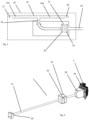
Fig. 1 is a schematic view of a thermal unit of a vehicle that could be use with vacuum cleaner of the invention, and -
Fig. 2 is a schematic view of a vacuum cleaner according to the invention. - In reference to
figure 1 , athermal unit 10 of vehicle can typically include afan 11, aheater 12 and acooler 13. By means of thefan 11, outside air can be sucked in achannel 14, can enter thethermal unit 10 and pass through theheater 12 and thecooler 13. Therefore, thethermal unit 10 can provide a heated or cooled air flow F which will be directed towards the user compartment of the vehicle. In practice, theheater 12 can be a radiator, and thecooler 13 can be an evaporator forming part of a refrigerant circuit of an air conditioning system. Such a refrigerant circuit typically carries a refrigerant in a loop through a compressor, a condenser, an expander and an evaporator capable of cooling an air flow directed towards the user compartment. - The
thermal control system 10 also comprises air circuits connected to thethermal unit 10 and designed to carry some of the air flow towards various locations in the cabin and to blow it inside the user compartment. -
Figure 1 shows oneair circuit 15 which has aninlet 16 connected to thethermal unit 10 and twooutlets air circuit 15 can include: - a
first duct 15a having afirst outlet 17 which opens towards driver seat, for blowing air towards the driver's torso; - and a
second duct 15b having asecond outlet 18 which opens towards the passenger seat, for blowing air towards the passenger's torso; - Part of the air blown through
outlets air circuit 15 could be provided with more ducts and/or more outlets. - In
figure 2 , Thethermal control system 1 may comprise other air circuits (not shown), such as: an air conduit for blowing air towards the windscreen and/or the head of the cabin occupant(s); an air conduit for blowing air towards the feet of the cabin occupant(s) and/or the area located along the lower part of the side walls. - With reference to
figure 2 ,portable vacuum cleaner 2 according to the invention comprises a connectingdevice 20 to theexternal air duct 14 of the vehiclethermal control system 1. Theportable vacuum cleaner 2 also comprises aflexible hose 21 connected to the connection device and the other end of which is equipped with asuction head 24. - The
portable vacuum cleaner 2 according to the invention also comprises adust collection tray 22 mounted on theflexible hose 21. Thedust collection tray 22 may comprise adust filter 23. Thedust filter 23 is, for example, removably mounted indust tray 22 Thedust tray 22 is, for example, removably mounted on theflexible hose 21. For this purpose, thehose 21 and the dust container comprise connecting elements for maintaining an airtight seal between thehose 22 and thedust container 22. For example, the connecting elements comprise a sleeve mounted on thehose 21 and a hole in thedust container 22. The sleeve is then pressed into the dust container opening 22. A seal may be present in the dust container opening 22 to ensure a seal between thehose sleeve 21 and thedust container 22. - The
connection device 20 ofportable vacuum cleaner 2 according to the invention may comprise locking elements for holding onportable vacuum cleaner 2 upstream of thefan 11 of thethermal control device 1. The locking elements also allow theVacuum cleaner 2 to be disengaged from thethermal control device 1 whenvacuum cleaner 2 is no longer in use. - It is to be understood that the present invention is not limited to the embodiments described above and illustrated in the drawings; rather, the skilled person will recognize that many changes and modifications may be made within the scope of the appended claims.
Claims (6)
- Vacuum cleaner comprising a connecting device (20) to a thermal control system (1) of a vehicle, a flexible hose (21) with a connection end to connecting device (20) for creating suction into flexible hose, a dust collecting box (20) mounted onto flexible hose (21).
- Vacuum cleaner according to claim 1 in which dust collecting box (22) comprises a removable filter (23) for cleaning or maintenance.
- Vacuum cleaner according to claim 1 or 2 in which dust collecting box (22) is removable for cleaning or maintenance.
- Vacuum cleaner according to any of claims 1 to 3 in which connection device (20) comprises attachment element to an inlet blower (14) of thermal control system (1) of a vehicle.
- Vacuum cleaner according to claim 4 in which attachment element comprises sealing element to ensure airtight between connection device (20) and thermal control system (1) of a vehicle.
- Vacuum cleaner according to any of claims 1 to 5 in which flexible hose (21) comprise a vacuum head (24).
Priority Applications (3)
| Application Number | Priority Date | Filing Date | Title |
|---|---|---|---|
| EP22164558.3A EP4248816B1 (en) | 2022-03-25 | 2022-03-25 | A vacuum cleaner for interior of vehicle |
| US18/122,479 US20230301475A1 (en) | 2022-03-25 | 2023-03-16 | Vacuum cleaner for interior of vehicle |
| CN202310254710.6A CN116803773A (en) | 2022-03-25 | 2023-03-16 | A vacuum cleaner for vehicle interiors |
Applications Claiming Priority (1)
| Application Number | Priority Date | Filing Date | Title |
|---|---|---|---|
| EP22164558.3A EP4248816B1 (en) | 2022-03-25 | 2022-03-25 | A vacuum cleaner for interior of vehicle |
Publications (3)
| Publication Number | Publication Date |
|---|---|
| EP4248816A1 true EP4248816A1 (en) | 2023-09-27 |
| EP4248816C0 EP4248816C0 (en) | 2024-11-13 |
| EP4248816B1 EP4248816B1 (en) | 2024-11-13 |
Family
ID=80952129
Family Applications (1)
| Application Number | Title | Priority Date | Filing Date |
|---|---|---|---|
| EP22164558.3A Active EP4248816B1 (en) | 2022-03-25 | 2022-03-25 | A vacuum cleaner for interior of vehicle |
Country Status (3)
| Country | Link |
|---|---|
| US (1) | US20230301475A1 (en) |
| EP (1) | EP4248816B1 (en) |
| CN (1) | CN116803773A (en) |
Citations (3)
| Publication number | Priority date | Publication date | Assignee | Title |
|---|---|---|---|---|
| KR20040052071A (en) * | 2002-12-13 | 2004-06-19 | 현대모비스 주식회사 | A Cleaning Device For Motors Having The Filter |
| US20190184944A1 (en) * | 2017-12-15 | 2019-06-20 | Hyundai Motor Company | Air conditioning device for vehicle having vacuum cleaning function and control method thereof |
| WO2021181431A1 (en) * | 2020-03-13 | 2021-09-16 | D.A.J.T. Sas Di Bianucci Giacomo Davide | Motorized vehicle integrating a suction system acting in a compartment of said vehicle |
Family Cites Families (6)
| Publication number | Priority date | Publication date | Assignee | Title |
|---|---|---|---|---|
| CN1065043A (en) * | 1991-03-20 | 1992-10-07 | 陈永康 | Cleaning dust remover for automobile |
| RU2175519C1 (en) * | 2000-08-31 | 2001-11-10 | Адамович Борис Андреевич | Car vacuum cleaner |
| KR20030096911A (en) * | 2002-06-18 | 2003-12-31 | 황영출 | A Vacuum Cleaner Use OfA Heater And An Air Conditioner to Air Handling Unit From A Car |
| KR200330511Y1 (en) * | 2003-07-08 | 2003-10-17 | 문태주 | Vacuum cleaner for vehicle |
| CN104828022A (en) * | 2014-06-25 | 2015-08-12 | 北汽福田汽车股份有限公司 | Automobile |
| US11654868B2 (en) * | 2016-07-19 | 2023-05-23 | Shop Vac Corporation | Vacuum cleaner to be installed in a vehicle |
-
2022
- 2022-03-25 EP EP22164558.3A patent/EP4248816B1/en active Active
-
2023
- 2023-03-16 CN CN202310254710.6A patent/CN116803773A/en active Pending
- 2023-03-16 US US18/122,479 patent/US20230301475A1/en not_active Abandoned
Patent Citations (3)
| Publication number | Priority date | Publication date | Assignee | Title |
|---|---|---|---|---|
| KR20040052071A (en) * | 2002-12-13 | 2004-06-19 | 현대모비스 주식회사 | A Cleaning Device For Motors Having The Filter |
| US20190184944A1 (en) * | 2017-12-15 | 2019-06-20 | Hyundai Motor Company | Air conditioning device for vehicle having vacuum cleaning function and control method thereof |
| WO2021181431A1 (en) * | 2020-03-13 | 2021-09-16 | D.A.J.T. Sas Di Bianucci Giacomo Davide | Motorized vehicle integrating a suction system acting in a compartment of said vehicle |
Also Published As
| Publication number | Publication date |
|---|---|
| CN116803773A (en) | 2023-09-26 |
| EP4248816C0 (en) | 2024-11-13 |
| US20230301475A1 (en) | 2023-09-28 |
| EP4248816B1 (en) | 2024-11-13 |
Similar Documents
| Publication | Publication Date | Title |
|---|---|---|
| US8869547B2 (en) | Air conditioner of track system vehicle | |
| US7096925B2 (en) | Modular electric HVAC systems for vehicles | |
| US20110061414A1 (en) | Rooftop mounted air conditioner | |
| CN102958721B (en) | The agri-vehicle operator's compartment of HVAC system is installed | |
| US20140299076A1 (en) | Vehicle front portion structure | |
| AU4004199A (en) | Modular low pressure delivery vehicle air conditioning system | |
| CN105522887B (en) | Air conditioner for motor vehicle | |
| US20190184944A1 (en) | Air conditioning device for vehicle having vacuum cleaning function and control method thereof | |
| EP4248816B1 (en) | A vacuum cleaner for interior of vehicle | |
| CN103963603B (en) | Heating, ventilation and air conditioning pressure fan | |
| EP3932707A1 (en) | Isolated evaporator coil for a transport climate control system | |
| HU226705B1 (en) | Rail vehicle with an air-conditioned driver's cabin | |
| KR101554255B1 (en) | Vehicle air conditioning system | |
| US20170120727A1 (en) | Air shower device and air conditioning device | |
| CN115230425A (en) | Air conditioning equipment and vehicles | |
| CN214728058U (en) | Air duct type air conditioner structure for off-highway vehicle | |
| US11453268B2 (en) | Air conditioner system | |
| US20110016900A1 (en) | Cooling system for a motor vehicle | |
| JP6767341B2 (en) | Vehicle air conditioner | |
| JP2017140911A (en) | Air conditioner for vehicles | |
| JPH0550848A (en) | Air conditioner for vehicle | |
| EP4520931A1 (en) | Exhaust assembly for a prime mover of a transport power system | |
| JPS6342014Y2 (en) | ||
| JPH0140800Y2 (en) | ||
| JPH0450022A (en) | Aspirator structure of automatic air conditioning device |
Legal Events
| Date | Code | Title | Description |
|---|---|---|---|
| PUAI | Public reference made under article 153(3) epc to a published international application that has entered the european phase |
Free format text: ORIGINAL CODE: 0009012 |
|
| STAA | Information on the status of an ep patent application or granted ep patent |
Free format text: STATUS: THE APPLICATION HAS BEEN PUBLISHED |
|
| AK | Designated contracting states |
Kind code of ref document: A1 Designated state(s): AL AT BE BG CH CY CZ DE DK EE ES FI FR GB GR HR HU IE IS IT LI LT LU LV MC MK MT NL NO PL PT RO RS SE SI SK SM TR |
|
| STAA | Information on the status of an ep patent application or granted ep patent |
Free format text: STATUS: REQUEST FOR EXAMINATION WAS MADE |
|
| 17P | Request for examination filed |
Effective date: 20240326 |
|
| RBV | Designated contracting states (corrected) |
Designated state(s): AL AT BE BG CH CY CZ DE DK EE ES FI FR GB GR HR HU IE IS IT LI LT LU LV MC MK MT NL NO PL PT RO RS SE SI SK SM TR |
|
| GRAP | Despatch of communication of intention to grant a patent |
Free format text: ORIGINAL CODE: EPIDOSNIGR1 |
|
| STAA | Information on the status of an ep patent application or granted ep patent |
Free format text: STATUS: GRANT OF PATENT IS INTENDED |
|
| INTG | Intention to grant announced |
Effective date: 20240807 |
|
| GRAS | Grant fee paid |
Free format text: ORIGINAL CODE: EPIDOSNIGR3 |
|
| GRAA | (expected) grant |
Free format text: ORIGINAL CODE: 0009210 |
|
| STAA | Information on the status of an ep patent application or granted ep patent |
Free format text: STATUS: THE PATENT HAS BEEN GRANTED |
|
| AK | Designated contracting states |
Kind code of ref document: B1 Designated state(s): AL AT BE BG CH CY CZ DE DK EE ES FI FR GB GR HR HU IE IS IT LI LT LU LV MC MK MT NL NO PL PT RO RS SE SI SK SM TR |
|
| REG | Reference to a national code |
Ref country code: GB Ref legal event code: FG4D |
|
| REG | Reference to a national code |
Ref country code: CH Ref legal event code: EP |
|
| REG | Reference to a national code |
Ref country code: IE Ref legal event code: FG4D |
|
| REG | Reference to a national code |
Ref country code: DE Ref legal event code: R096 Ref document number: 602022007609 Country of ref document: DE |
|
| U01 | Request for unitary effect filed |
Effective date: 20241211 |
|
| U07 | Unitary effect registered |
Designated state(s): AT BE BG DE DK EE FI FR IT LT LU LV MT NL PT RO SE SI Effective date: 20241219 |
|
| PG25 | Lapsed in a contracting state [announced via postgrant information from national office to epo] |
Ref country code: HR Free format text: LAPSE BECAUSE OF FAILURE TO SUBMIT A TRANSLATION OF THE DESCRIPTION OR TO PAY THE FEE WITHIN THE PRESCRIBED TIME-LIMIT Effective date: 20241113 Ref country code: IS Free format text: LAPSE BECAUSE OF FAILURE TO SUBMIT A TRANSLATION OF THE DESCRIPTION OR TO PAY THE FEE WITHIN THE PRESCRIBED TIME-LIMIT Effective date: 20250313 |
|
| PG25 | Lapsed in a contracting state [announced via postgrant information from national office to epo] |
Ref country code: ES Free format text: LAPSE BECAUSE OF FAILURE TO SUBMIT A TRANSLATION OF THE DESCRIPTION OR TO PAY THE FEE WITHIN THE PRESCRIBED TIME-LIMIT Effective date: 20241113 |
|
| PG25 | Lapsed in a contracting state [announced via postgrant information from national office to epo] |
Ref country code: NO Free format text: LAPSE BECAUSE OF FAILURE TO SUBMIT A TRANSLATION OF THE DESCRIPTION OR TO PAY THE FEE WITHIN THE PRESCRIBED TIME-LIMIT Effective date: 20250213 |
|
| PG25 | Lapsed in a contracting state [announced via postgrant information from national office to epo] |
Ref country code: GR Free format text: LAPSE BECAUSE OF FAILURE TO SUBMIT A TRANSLATION OF THE DESCRIPTION OR TO PAY THE FEE WITHIN THE PRESCRIBED TIME-LIMIT Effective date: 20250214 |
|
| PG25 | Lapsed in a contracting state [announced via postgrant information from national office to epo] |
Ref country code: PL Free format text: LAPSE BECAUSE OF FAILURE TO SUBMIT A TRANSLATION OF THE DESCRIPTION OR TO PAY THE FEE WITHIN THE PRESCRIBED TIME-LIMIT Effective date: 20241113 |
|
| PG25 | Lapsed in a contracting state [announced via postgrant information from national office to epo] |
Ref country code: RS Free format text: LAPSE BECAUSE OF FAILURE TO SUBMIT A TRANSLATION OF THE DESCRIPTION OR TO PAY THE FEE WITHIN THE PRESCRIBED TIME-LIMIT Effective date: 20250213 |
|
| U20 | Renewal fee for the european patent with unitary effect paid |
Year of fee payment: 4 Effective date: 20250325 |
|
| PG25 | Lapsed in a contracting state [announced via postgrant information from national office to epo] |
Ref country code: SM Free format text: LAPSE BECAUSE OF FAILURE TO SUBMIT A TRANSLATION OF THE DESCRIPTION OR TO PAY THE FEE WITHIN THE PRESCRIBED TIME-LIMIT Effective date: 20241113 |
|
| PG25 | Lapsed in a contracting state [announced via postgrant information from national office to epo] |
Ref country code: SK Free format text: LAPSE BECAUSE OF FAILURE TO SUBMIT A TRANSLATION OF THE DESCRIPTION OR TO PAY THE FEE WITHIN THE PRESCRIBED TIME-LIMIT Effective date: 20241113 |
|
| PG25 | Lapsed in a contracting state [announced via postgrant information from national office to epo] |
Ref country code: CZ Free format text: LAPSE BECAUSE OF FAILURE TO SUBMIT A TRANSLATION OF THE DESCRIPTION OR TO PAY THE FEE WITHIN THE PRESCRIBED TIME-LIMIT Effective date: 20241113 |
|
| PLBE | No opposition filed within time limit |
Free format text: ORIGINAL CODE: 0009261 |
|
| STAA | Information on the status of an ep patent application or granted ep patent |
Free format text: STATUS: NO OPPOSITION FILED WITHIN TIME LIMIT |
|
| PG25 | Lapsed in a contracting state [announced via postgrant information from national office to epo] |
Ref country code: MC Free format text: LAPSE BECAUSE OF FAILURE TO SUBMIT A TRANSLATION OF THE DESCRIPTION OR TO PAY THE FEE WITHIN THE PRESCRIBED TIME-LIMIT Effective date: 20241113 |
|
| 26N | No opposition filed |
Effective date: 20250814 |
|
| REG | Reference to a national code |
Ref country code: CH Ref legal event code: H13 Free format text: ST27 STATUS EVENT CODE: U-0-0-H10-H13 (AS PROVIDED BY THE NATIONAL OFFICE) Effective date: 20251023 |
|
| PG25 | Lapsed in a contracting state [announced via postgrant information from national office to epo] |
Ref country code: CH Free format text: LAPSE BECAUSE OF NON-PAYMENT OF DUE FEES Effective date: 20250331 |
|
| PG25 | Lapsed in a contracting state [announced via postgrant information from national office to epo] |
Ref country code: IE Free format text: LAPSE BECAUSE OF NON-PAYMENT OF DUE FEES Effective date: 20250325 |
|
| U20 | Renewal fee for the european patent with unitary effect paid |
Year of fee payment: 5 Effective date: 20260323 |