EP4248257B1 - Fiber positioning unit for telescopes - Google Patents
Fiber positioning unit for telescopes Download PDFInfo
- Publication number
- EP4248257B1 EP4248257B1 EP21827648.3A EP21827648A EP4248257B1 EP 4248257 B1 EP4248257 B1 EP 4248257B1 EP 21827648 A EP21827648 A EP 21827648A EP 4248257 B1 EP4248257 B1 EP 4248257B1
- Authority
- EP
- European Patent Office
- Prior art keywords
- focal plate
- alpha
- motor
- beta
- fpu
- Prior art date
- Legal status (The legal status is an assumption and is not a legal conclusion. Google has not performed a legal analysis and makes no representation as to the accuracy of the status listed.)
- Active
Links
Images


Classifications
-
- G—PHYSICS
- G02—OPTICS
- G02B—OPTICAL ELEMENTS, SYSTEMS OR APPARATUS
- G02B26/00—Optical devices or arrangements for the control of light using movable or deformable optical elements
- G02B26/08—Optical devices or arrangements for the control of light using movable or deformable optical elements for controlling the direction of light
- G02B26/10—Scanning systems
- G02B26/103—Scanning systems having movable or deformable optical fibres, light guides or waveguides as scanning elements
-
- G—PHYSICS
- G02—OPTICS
- G02B—OPTICAL ELEMENTS, SYSTEMS OR APPARATUS
- G02B6/00—Light guides; Structural details of arrangements comprising light guides and other optical elements, e.g. couplings
- G02B6/24—Coupling light guides
- G02B6/36—Mechanical coupling means
- G02B6/3604—Rotary joints allowing relative rotational movement between opposing fibre or fibre bundle ends
Definitions
- the present invention relates to a Fibre Positioning Unit (FPU) for telescopes. It more precisely concerns a FPU of the SCARA type.
- FPU Fibre Positioning Unit
- a FPU of the SCARA type uses two parallel rotary joints to position a fibre free end within an annular workspace (see figure 1 ).
- the FPU are fixed to a focal plate.
- Figure 3 represents a front view of a focal plate.
- Pitch distance center to center
- FPU diameter the pitch between two adjacent FPU
- the graph of figure 4 shows the number of FPU for a focal plate of 800mm in diameter with respect to the positioner pitch.
- Figure 5 shows an FPU according to the state of the art.
- the FPU design is made of a single part.
- the optical fibre and the beta motor wires must be bent to pass on the side of the alpha motor. Any bending of the optical fibre fiber reduces the system performance from an optical point of view.
- Figure 6 shows a tentative to miniaturize an FPU, with a diameter of approx. 7 mm.
- Such a relatively small object requires the use of an extremely small motor, typically 2 mm in diameter. This affects, i.e. reduces, the system performances (torque, precision, repeatability and robustness).
- a FPU of the SCARA type usually comprises an alpha and a beta mechanism; the alpha mechanism successively comprising a motor, a driving shaft and a rotatable shaft (often a hollow shaft), the rotation of the rotatable shaft being carried out by the alpha motor via the driving shaft.
- the beta mechanism comprises a motor and a fibre holding element that may be rotated by the beta motor 4. Both mechanisms are mechanically connected in a way to allow a rotation of the beta mechanism by the rotatable shaft.
- the rotatable shaft is located within or above a focal plate.
- the FPU disclosed in Chinese patent documents CN1095085C and CN2344786Y notably reduces the bending of the optical effect (see figure 7 ).
- Another FPU mechanism is disclosed by MONTGOMERY DAVID ET AL: "Development of the fibre positioning unit of MOONS", PROCEEDINGS OF SPIE; ISSN 0277-786X VOLUME 10524 ], SPIE, US, vol. 9908, 4 August 2016 (2016-08-04), pages 990895-990895, DOI: 10.1117/12.2234183ISBN: 978-1-5106-1533-5 .
- FPU have been designed in a single part, that integrates the two motors.
- the FPU is mounted in one step on the focal plate (see figure 8 ).
- the FPU according to the invention is essentially made in two separated parts and may be mounted on the focal plate in two distinct and independent steps.
- the central axis of the FPU and the alpha motor are not concentric. With such a configuration, the optical fibre may be maintained essentially straight along the FPU body.
- This configuration also allows the use of motors with a diameter very close to the diameter of the pitch for the rotatable shaft, typically of 6mm, which results in an increase of the FPU density on the focal plate.
- the use of an alpha motor and gearbox with a diameter very close to the pitch makes the complete design more robust and precise for a given pitch.
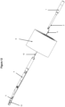
- Figure 9 shows an example of a FPU according to the invention with the optical fibre 10 being straight and placed between two adjacent alpha motors 1.
Landscapes
- Physics & Mathematics (AREA)
- General Physics & Mathematics (AREA)
- Optics & Photonics (AREA)
- Optical Couplings Of Light Guides (AREA)
- Seal Device For Vehicle (AREA)
- Prostheses (AREA)
- Manipulator (AREA)
- Surgical Instruments (AREA)
Description
- The present invention relates to a Fibre Positioning Unit (FPU) for telescopes. It more precisely concerns a FPU of the SCARA type.
- A FPU of the SCARA type uses two parallel rotary joints to position a fibre free end within an annular workspace (see
figure 1 ). - Examples of existing FPU are shown in
figure 2 ,5 and6 . - The FPU are fixed to a focal plate.
Figure 3 represents a front view of a focal plate. Nowadays, a maximum densification of FPU on the focal plate is desired, to increase the instrument throughput. Thus, the pitch between two adjacent FPU (Pitch = distance center to center), and therefore the FPU diameter, should be minimized. - The graph of
figure 4 shows the number of FPU for a focal plate of 800mm in diameter with respect to the positioner pitch. -
Figure 5 shows an FPU according to the state of the art. The FPU design is made of a single part. The optical fibre and the beta motor wires must be bent to pass on the side of the alpha motor. Any bending of the optical fibre fiber reduces the system performance from an optical point of view. -
Figure 6 shows a tentative to miniaturize an FPU, with a diameter of approx. 7 mm. - Such a relatively small object requires the use of an extremely small motor, typically 2 mm in diameter. This affects, i.e. reduces, the system performances (torque, precision, repeatability and robustness).
- A FPU of the SCARA type usually comprises an alpha and a beta mechanism; the alpha mechanism successively comprising a motor, a driving shaft and a rotatable shaft (often a hollow shaft), the rotation of the rotatable shaft being carried out by the alpha motor via the driving shaft. The beta mechanism comprises a motor and a fibre holding element that may be rotated by the beta motor 4. Both mechanisms are mechanically connected in a way to allow a rotation of the beta mechanism by the rotatable shaft. The rotatable shaft is located within or above a focal plate.
- The FPU disclosed in Chinese patent documents
CN1095085C andCN2344786Y notably reduces the bending of the optical effect (seefigure 7 ). Another FPU mechanism is disclosed by MONTGOMERY DAVID ET AL: "Development of the fibre positioning unit of MOONS", PROCEEDINGS OF SPIE; ISSN 0277-786X VOLUME 10524], SPIE, US, vol. 9908, 4 August 2016 (2016-08-04), pages 990895-990895, DOI: 10.1117/12.2234183ISBN: 978-1-5106-1533-5. - Until now, FPU have been designed in a single part, that integrates the two motors.
- The FPU is mounted in one step on the focal plate (see
figure 8 ). - Prior art FPU, in particular the previous ones cited in the previous cited Chinese patent documents, do however pose some challenges and/or problems, such as:
- A focal plate needs to be precise on both sides in order to position the ball bearings.
- A complex assembly has to be done directly on and within the focal plate: 1) Press fitting of the ball bearings from both sides. 2) Insertion of the FPU. 3) Insertion and fixation of a gear (by gluing or laser welding) on the rotatable shaft. 4) fixation of the motor. Such an assembly cannot be made for a high FPU density configuration.
- The rotatable shaft is in the focal plate, which means that a relatively large bore has to be drilled through the focal plate reducing its rigidity (which is critical with the mass of thousands of FPUs)
- It is impossible to test the performances of the FPU before its fixation to the focal plate. The assembly process into the focal plate being irreversible, if bad performances of a positioner are detected at this stage, it compromises the complete telescope performances. This simply prohibits the use of such approach for high density FPU telescopes.
- There is therefore a need to improve the existing FPU to obtain a higher FPU density and a stronger stability of the general structure.
- The problems mentioned in the previous chapter are solved with the FPU of present invention. The invention is defined in the appended claims.
- The FPU according to the invention is essentially made in two separated parts and may be mounted on the focal plate in two distinct and independent steps. The central axis of the FPU and the alpha motor are not concentric. With such a configuration, the optical fibre may be maintained essentially straight along the FPU body. This configuration also allows the use of motors with a diameter very close to the diameter of the pitch for the rotatable shaft, typically of 6mm, which results in an increase of the FPU density on the focal plate. The use of an alpha motor and gearbox with a diameter very close to the pitch makes the complete design more robust and precise for a given pitch.
-
-
Figure 1 : Prior art FPU of the SCARA type -
Figure 2 : Other example of a prior art FPU -
Figure 3 : Front view of a prior art focal plate -
Figure 4 : Graph showing the density of FPU on a focal plate -
Figure 5 : Other example of a prior art FPU -
Figure 6 : Other example of a prior art FPU -
Figure 7 : Other example of a prior art FPU -
Figure 8 : Mounting of a FPU on a focal plate -
Figure 9 : Example of a FPU according to the invention -
Figure 10 :Front view of a focal plate according to the invention -
Figure 11 : Other view of the FPU offigure 9 -
Figure 12 : Other view of the FPU offigure 9 -
- 1. Alpha motor
- 2. Driving shaft
- 3. Hollow rotatable shaft
- 4. Beta motor
- 5. Fibre holding element
- 6. Focal plate
- 7. Driving shaft passage
- 8. Optic fibre passage
- 9. Electric wire passage
- 10. Optical fibre
- 11. Beta motor electric wire
-
Figure 9 shows an example of a FPU according to the invention with theoptical fibre 10 being straight and placed between twoadjacent alpha motors 1. - The FPU according to the present invention provides the following advantages:
- The
focal plate 6 may be more easily manufactured. - Assembling the FPUs on the
focal plate 6 does not require any complex process. - FPUs are preferably screwed, the
alpha motor 1 being inserted on one side of thefocal plate 6 and held in position by friction and thebeta mechanism 4,11 being positioned and fixed on the other side of thefocal plate 6. A press fitted pin may be advantageously used to avoid rotation of the motor. (No glue or laser welding are required). - The alpha rotatable shaft 3 and the
beta mechanism 4,11 are on the same side of thefocal plate 6, thepassages focal plate 6 are therefore relatively small, which results in a more robust structure. - It is possible to test the performances of each positioner before assembling it on the
focal plate 6.
Claims (7)
- Fiber positioning unit of SCARA type comprising an alpha (1,2,3) and a beta mechanism (4,5); the alpha mechanism successively comprising a motor (1), a driving shaft (2) and a rotatable shaft (3), the rotation of the rotatable shaft (3) being carried out by the alpha motor (1) via the driving shaft (2); the beta mechanism comprising a motor (4) and a fiber holding element (5) that may be rotated by the beta motor (4); both mechanisms being mechanically connected in a way to allow a rotation of the beta mechanism (4,5) by the rotatable shaft (3); the alpha mechanism (1,2,3) being furthermore adapted to be partially located within a focal plate (6), characterized by the fact that the alpha motor (1) is adapted to be located on one side of the focal plate (6) while the alpha rotatable shaft (3) and the beta mechanism (4,5) are adapted to be located mainly on the other side of the focal plate (6).
- Fiber positioning unit according to claim 1 wherein the rotatable shaft (3) at least partially extends through the focal plate (6).
- Fiber positioning unit according to claim 1 wherein the motor diameter (alpha or beta) is comprised between 2 and 6 mm.
- Assembly comprising a focal plate and several fiber positioning units as defined in claim 1, 2 or 3, the focal plate (6) comprising passages (7,8,9) with different diameters, wherein the greatest diameter is approximatively equivalent to the diameter of the driving shaft (2).
- Assembly according to claim 4 wherein said focal plate consists of a plurality of sub-modules.
- Method for assembling fiber positioning units as defined in claim 1 on a focal plate wherein the alpha motor (1) is inserted and fixed on one side of the focal plate and wherein the beta mechanism (4,5) is positioned and fixed on the other side of the focal plate (6).
- Method according to claim 8 wherein the alpha motor (1) and the beta mechanism (4,5) are mounted on the focal plate (6) in two distinct and independent steps.
Applications Claiming Priority (2)
| Application Number | Priority Date | Filing Date | Title |
|---|---|---|---|
| IB2020060955 | 2020-11-20 | ||
| PCT/IB2021/060564 WO2022106983A2 (en) | 2020-11-20 | 2021-11-15 | Fiber positioning unit for telescopes |
Publications (3)
| Publication Number | Publication Date |
|---|---|
| EP4248257A2 EP4248257A2 (en) | 2023-09-27 |
| EP4248257C0 EP4248257C0 (en) | 2025-04-09 |
| EP4248257B1 true EP4248257B1 (en) | 2025-04-09 |
Family
ID=78957955
Family Applications (1)
| Application Number | Title | Priority Date | Filing Date |
|---|---|---|---|
| EP21827648.3A Active EP4248257B1 (en) | 2020-11-20 | 2021-11-15 | Fiber positioning unit for telescopes |
Country Status (5)
| Country | Link |
|---|---|
| US (1) | US12339439B2 (en) |
| EP (1) | EP4248257B1 (en) |
| CN (1) | CN116888441A (en) |
| AU (1) | AU2021381704A1 (en) |
| WO (1) | WO2022106983A2 (en) |
Families Citing this family (2)
| Publication number | Priority date | Publication date | Assignee | Title |
|---|---|---|---|---|
| CN117182900B (en) * | 2023-09-12 | 2026-01-27 | 中国科学技术大学 | Anti-collision operation planning method for optical fiber operation of multi-target optical fiber spectrum astronomical telescope |
| WO2025074195A1 (en) | 2023-10-04 | 2025-04-10 | Mps Micro Precision Systems Ag | System for positioning optical fibres in a telescope |
Family Cites Families (5)
| Publication number | Priority date | Publication date | Assignee | Title |
|---|---|---|---|---|
| CN1095085C (en) * | 1997-03-11 | 2002-11-27 | 中国科学技术大学 | Fibre-optical unit positioning apparatus for astronomy spectrotelescope |
| CN2344786Y (en) | 1998-11-16 | 1999-10-20 | 中国科学技术大学 | Double-rotating fiber optic unit positioning device for spectroscopic astronomical telescope |
| EP1259841A4 (en) * | 2000-02-01 | 2005-09-07 | Soquel Technology Inc | SINGLE CHANNEL M x N OPTICAL FIBER SWITCH |
| US7304296B2 (en) * | 2005-10-05 | 2007-12-04 | Raytheon Company | Optical fiber assembly wrapped across gimbal axes |
| US8373852B2 (en) * | 2007-11-26 | 2013-02-12 | Exfo Inc. | Optical waveguide rotator mechanism, birefringence-inducing element and polarization control devices employing either or both and methods of using same |
-
2021
- 2021-11-15 AU AU2021381704A patent/AU2021381704A1/en active Pending
- 2021-11-15 EP EP21827648.3A patent/EP4248257B1/en active Active
- 2021-11-15 CN CN202180077884.9A patent/CN116888441A/en active Pending
- 2021-11-15 US US18/253,821 patent/US12339439B2/en active Active
- 2021-11-15 WO PCT/IB2021/060564 patent/WO2022106983A2/en not_active Ceased
Also Published As
| Publication number | Publication date |
|---|---|
| WO2022106983A2 (en) | 2022-05-27 |
| EP4248257C0 (en) | 2025-04-09 |
| US20240004187A1 (en) | 2024-01-04 |
| US12339439B2 (en) | 2025-06-24 |
| AU2021381704A1 (en) | 2023-06-08 |
| CN116888441A (en) | 2023-10-13 |
| EP4248257A2 (en) | 2023-09-27 |
| WO2022106983A3 (en) | 2022-07-21 |
| AU2021381704A9 (en) | 2025-03-20 |
Similar Documents
| Publication | Publication Date | Title |
|---|---|---|
| US12339439B2 (en) | Fiber positioning unit for telescopes | |
| US6636664B2 (en) | Single channel M x N optical fiber switch | |
| US7764856B2 (en) | Device for injecting light into an optical wave guide | |
| WO2012172869A1 (en) | Optical fiber connection method and optical fiber connection structure | |
| US5800069A (en) | Compound bearing assembly | |
| US6796720B2 (en) | Optical component | |
| CN1448747A (en) | Optical fiber array and method of manufacturing the same | |
| EP3540486B1 (en) | Compact multichannel optical rotary joint | |
| US11314019B2 (en) | Capillary-type lens array and capillary-type lens array composite component | |
| WO2022013275A1 (en) | Optical rotary transmitter, method for manufacture, test method and use | |
| US6302593B1 (en) | Fiber optic connector with micro-alignable lenses and associated fabrication method | |
| US4711521A (en) | Method of manufacturing a terminal device for an optical fiber, and device thus obtained | |
| JP7513127B2 (en) | Optical Switch | |
| US20030202737A1 (en) | Optical switch | |
| EP1450188B1 (en) | Optic fiber terminus indexer | |
| CN1095085C (en) | Fibre-optical unit positioning apparatus for astronomy spectrotelescope | |
| US11513296B2 (en) | Optical component, optical connection component with graded index lens, and method of manufacturing optical component | |
| JP3268541B2 (en) | Optical coupling method | |
| US7689091B1 (en) | Unitary fiber clamp with flexible members and a member mover | |
| US7231126B2 (en) | Flexure arrangements | |
| CN223582204U (en) | An optical path structure and optical module for wavelength division multiplexing (WDM) integrated optical components | |
| US6704389B1 (en) | Support device for a polycapillary optic | |
| US6666588B1 (en) | Collimator array having precisely aligned optical beams and method of assembling same | |
| KR20010094690A (en) | Photo Switch and Moter Control Switch Using Photo Element and Holder | |
| JP2001042160A (en) | Different diameter ferrule combining alignment sleeve |
Legal Events
| Date | Code | Title | Description |
|---|---|---|---|
| STAA | Information on the status of an ep patent application or granted ep patent |
Free format text: STATUS: UNKNOWN |
|
| STAA | Information on the status of an ep patent application or granted ep patent |
Free format text: STATUS: THE INTERNATIONAL PUBLICATION HAS BEEN MADE |
|
| PUAI | Public reference made under article 153(3) epc to a published international application that has entered the european phase |
Free format text: ORIGINAL CODE: 0009012 |
|
| STAA | Information on the status of an ep patent application or granted ep patent |
Free format text: STATUS: REQUEST FOR EXAMINATION WAS MADE |
|
| 17P | Request for examination filed |
Effective date: 20230601 |
|
| AK | Designated contracting states |
Kind code of ref document: A2 Designated state(s): AL AT BE BG CH CY CZ DE DK EE ES FI FR GB GR HR HU IE IS IT LI LT LU LV MC MK MT NL NO PL PT RO RS SE SI SK SM TR |
|
| DAV | Request for validation of the european patent (deleted) | ||
| DAX | Request for extension of the european patent (deleted) | ||
| RIC1 | Information provided on ipc code assigned before grant |
Ipc: G02B 6/36 20060101ALI20240930BHEP Ipc: G01J 3/02 20060101ALI20240930BHEP Ipc: G02B 7/00 20210101ALI20240930BHEP Ipc: G02B 23/26 20060101ALI20240930BHEP Ipc: G02B 7/183 20210101ALI20240930BHEP Ipc: G02B 26/10 20060101AFI20240930BHEP |
|
| GRAP | Despatch of communication of intention to grant a patent |
Free format text: ORIGINAL CODE: EPIDOSNIGR1 |
|
| STAA | Information on the status of an ep patent application or granted ep patent |
Free format text: STATUS: GRANT OF PATENT IS INTENDED |
|
| INTG | Intention to grant announced |
Effective date: 20241114 |
|
| GRAS | Grant fee paid |
Free format text: ORIGINAL CODE: EPIDOSNIGR3 |
|
| GRAA | (expected) grant |
Free format text: ORIGINAL CODE: 0009210 |
|
| STAA | Information on the status of an ep patent application or granted ep patent |
Free format text: STATUS: THE PATENT HAS BEEN GRANTED |
|
| AK | Designated contracting states |
Kind code of ref document: B1 Designated state(s): AL AT BE BG CH CY CZ DE DK EE ES FI FR GB GR HR HU IE IS IT LI LT LU LV MC MK MT NL NO PL PT RO RS SE SI SK SM TR |
|
| REG | Reference to a national code |
Ref country code: GB Ref legal event code: FG4D |
|
| REG | Reference to a national code |
Ref country code: CH Ref legal event code: EP |
|
| REG | Reference to a national code |
Ref country code: DE Ref legal event code: R096 Ref document number: 602021029026 Country of ref document: DE |
|
| REG | Reference to a national code |
Ref country code: IE Ref legal event code: FG4D |
|
| U01 | Request for unitary effect filed |
Effective date: 20250429 |
|
| U07 | Unitary effect registered |
Designated state(s): AT BE BG DE DK EE FI FR IT LT LU LV MT NL PT RO SE SI Effective date: 20250507 |
|
| PG25 | Lapsed in a contracting state [announced via postgrant information from national office to epo] |
Ref country code: ES Free format text: LAPSE BECAUSE OF FAILURE TO SUBMIT A TRANSLATION OF THE DESCRIPTION OR TO PAY THE FEE WITHIN THE PRESCRIBED TIME-LIMIT Effective date: 20250409 |
|
| PG25 | Lapsed in a contracting state [announced via postgrant information from national office to epo] |
Ref country code: NO Free format text: LAPSE BECAUSE OF FAILURE TO SUBMIT A TRANSLATION OF THE DESCRIPTION OR TO PAY THE FEE WITHIN THE PRESCRIBED TIME-LIMIT Effective date: 20250709 Ref country code: GR Free format text: LAPSE BECAUSE OF FAILURE TO SUBMIT A TRANSLATION OF THE DESCRIPTION OR TO PAY THE FEE WITHIN THE PRESCRIBED TIME-LIMIT Effective date: 20250710 |
|
| PG25 | Lapsed in a contracting state [announced via postgrant information from national office to epo] |
Ref country code: PL Free format text: LAPSE BECAUSE OF FAILURE TO SUBMIT A TRANSLATION OF THE DESCRIPTION OR TO PAY THE FEE WITHIN THE PRESCRIBED TIME-LIMIT Effective date: 20250409 |
|
| PG25 | Lapsed in a contracting state [announced via postgrant information from national office to epo] |
Ref country code: HR Free format text: LAPSE BECAUSE OF FAILURE TO SUBMIT A TRANSLATION OF THE DESCRIPTION OR TO PAY THE FEE WITHIN THE PRESCRIBED TIME-LIMIT Effective date: 20250409 |
|
| PG25 | Lapsed in a contracting state [announced via postgrant information from national office to epo] |
Ref country code: RS Free format text: LAPSE BECAUSE OF FAILURE TO SUBMIT A TRANSLATION OF THE DESCRIPTION OR TO PAY THE FEE WITHIN THE PRESCRIBED TIME-LIMIT Effective date: 20250709 |
|
| PG25 | Lapsed in a contracting state [announced via postgrant information from national office to epo] |
Ref country code: IS Free format text: LAPSE BECAUSE OF FAILURE TO SUBMIT A TRANSLATION OF THE DESCRIPTION OR TO PAY THE FEE WITHIN THE PRESCRIBED TIME-LIMIT Effective date: 20250809 |
|
| REG | Reference to a national code |
Ref country code: CH Ref legal event code: U11 Free format text: ST27 STATUS EVENT CODE: U-0-0-U10-U11 (AS PROVIDED BY THE NATIONAL OFFICE) Effective date: 20251201 |
|
| U20 | Renewal fee for the european patent with unitary effect paid |
Year of fee payment: 5 Effective date: 20251127 |
|
| PGFP | Annual fee paid to national office [announced via postgrant information from national office to epo] |
Ref country code: GB Payment date: 20251121 Year of fee payment: 5 |
|
| PG25 | Lapsed in a contracting state [announced via postgrant information from national office to epo] |
Ref country code: SM Free format text: LAPSE BECAUSE OF FAILURE TO SUBMIT A TRANSLATION OF THE DESCRIPTION OR TO PAY THE FEE WITHIN THE PRESCRIBED TIME-LIMIT Effective date: 20250409 |
|
| PGFP | Annual fee paid to national office [announced via postgrant information from national office to epo] |
Ref country code: CH Payment date: 20251201 Year of fee payment: 5 |
|
| PG25 | Lapsed in a contracting state [announced via postgrant information from national office to epo] |
Ref country code: CZ Free format text: LAPSE BECAUSE OF FAILURE TO SUBMIT A TRANSLATION OF THE DESCRIPTION OR TO PAY THE FEE WITHIN THE PRESCRIBED TIME-LIMIT Effective date: 20250409 |
|
| PG25 | Lapsed in a contracting state [announced via postgrant information from national office to epo] |
Ref country code: SK Free format text: LAPSE BECAUSE OF FAILURE TO SUBMIT A TRANSLATION OF THE DESCRIPTION OR TO PAY THE FEE WITHIN THE PRESCRIBED TIME-LIMIT Effective date: 20250409 |
|
| PLBE | No opposition filed within time limit |
Free format text: ORIGINAL CODE: 0009261 |
|
| STAA | Information on the status of an ep patent application or granted ep patent |
Free format text: STATUS: NO OPPOSITION FILED WITHIN TIME LIMIT |
|
| REG | Reference to a national code |
Ref country code: CH Ref legal event code: L10 Free format text: ST27 STATUS EVENT CODE: U-0-0-L10-L00 (AS PROVIDED BY THE NATIONAL OFFICE) Effective date: 20260218 |
|
| 26N | No opposition filed |
Effective date: 20260112 |
|
| U1N | Appointed representative for the unitary patent procedure changed after the registration of the unitary effect |
Representative=s name: MARKS & CLERK LLP; GB |