EP4247213B1 - Gutter broom - Google Patents
Gutter broom Download PDFInfo
- Publication number
- EP4247213B1 EP4247213B1 EP21831144.7A EP21831144A EP4247213B1 EP 4247213 B1 EP4247213 B1 EP 4247213B1 EP 21831144 A EP21831144 A EP 21831144A EP 4247213 B1 EP4247213 B1 EP 4247213B1
- Authority
- EP
- European Patent Office
- Prior art keywords
- carrier
- bristle
- aspects
- mandrel
- gutter broom
- Prior art date
- Legal status (The legal status is an assumption and is not a legal conclusion. Google has not performed a legal analysis and makes no representation as to the accuracy of the status listed.)
- Active
Links
Images










Classifications
-
- A—HUMAN NECESSITIES
- A46—BRUSHWARE
- A46B—BRUSHES
- A46B3/00—Brushes characterised by the way in which the bristles are fixed or joined in or on the brush body or carrier
- A46B3/08—Brushes characterised by the way in which the bristles are fixed or joined in or on the brush body or carrier by clamping
- A46B3/10—Brushes characterised by the way in which the bristles are fixed or joined in or on the brush body or carrier by clamping into rings or the like
- A46B3/14—Brushes characterised by the way in which the bristles are fixed or joined in or on the brush body or carrier by clamping into rings or the like specially adapted for street-cleaning or rail-cleaning brooms
-
- A—HUMAN NECESSITIES
- A46—BRUSHWARE
- A46B—BRUSHES
- A46B7/00—Bristle carriers arranged in the brush body
- A46B7/04—Bristle carriers arranged in the brush body interchangeably removable bristle carriers
- A46B7/042—Clip or snap connection for bristle carriers
-
- A—HUMAN NECESSITIES
- A46—BRUSHWARE
- A46B—BRUSHES
- A46B13/00—Brushes with driven brush bodies or carriers
- A46B13/008—Disc-shaped brush bodies
-
- A—HUMAN NECESSITIES
- A46—BRUSHWARE
- A46B—BRUSHES
- A46B3/00—Brushes characterised by the way in which the bristles are fixed or joined in or on the brush body or carrier
- A46B3/16—Brushes characterised by the way in which the bristles are fixed or joined in or on the brush body or carrier by wires or other anchoring means, specially for U-shaped bristle tufts
-
- A—HUMAN NECESSITIES
- A46—BRUSHWARE
- A46B—BRUSHES
- A46B7/00—Bristle carriers arranged in the brush body
- A46B7/04—Bristle carriers arranged in the brush body interchangeably removable bristle carriers
- A46B7/044—Sliding connections for bristle carriers
-
- A—HUMAN NECESSITIES
- A46—BRUSHWARE
- A46B—BRUSHES
- A46B9/00—Arrangements of the bristles in the brush body
- A46B9/02—Position or arrangement of bristles in relation to surface of the brush body, e.g. inclined, in rows, in groups
-
- A—HUMAN NECESSITIES
- A46—BRUSHWARE
- A46D—MANUFACTURE OF BRUSHES
- A46D1/00—Bristles; Selection of materials for bristles
- A46D1/02—Bristles details
- A46D1/0207—Bristles characterised by the choice of material, e.g. metal
-
- E—FIXED CONSTRUCTIONS
- E01—CONSTRUCTION OF ROADS, RAILWAYS, OR BRIDGES
- E01H—STREET CLEANING; CLEANING OF PERMANENT WAYS; CLEANING BEACHES; DISPERSING OR PREVENTING FOG IN GENERAL CLEANING STREET OR RAILWAY FURNITURE OR TUNNEL WALLS
- E01H1/00—Removing undesirable matter from roads or like surfaces, with or without moistening of the surface
- E01H1/02—Brushing apparatus, e.g. with auxiliary instruments for mechanically loosening dirt
- E01H1/05—Brushing apparatus, e.g. with auxiliary instruments for mechanically loosening dirt with driven brushes
- E01H1/053—Brushing apparatus, e.g. with auxiliary instruments for mechanically loosening dirt with driven brushes having vertical axes
-
- A—HUMAN NECESSITIES
- A46—BRUSHWARE
- A46B—BRUSHES
- A46B2200/00—Brushes characterized by their functions, uses or applications
- A46B2200/30—Brushes for cleaning or polishing
- A46B2200/3066—Brush specifically designed for use with street cleaning machinery
Definitions
- the present disclosure relates to sweepers for cleaning surfaces.
- gutter brooms for cleaning roads, streets, and other surfaces.
- Sweepers can be used to remove debris and particulate matter from various surfaces.
- a gutter broom can be used to clean roads, streets, and other surfaces and can be mounted onto a surface cleaning vehicle to move across the surface.
- the gutter broom can also approach a curb or a side of a building to remove debris.
- the gutter broom can include a brush mount that receives brush bristles for sweeping.
- FR 2479713 A1 (Reislander KG Fabrik Tech) published 9 October 1981 discloses a circular brush with bristles, bent over at the centre, of each bristle tuft are gripped, in the bent-over region, in an elongate sleeve, said sleeves being pushed into retaining profiles.
- the retaining profiles each exhibit, corresponding to the outer shape of the sleeves, a hollow cross-section which is rounded out widely to the side in the bent-over region and is constricted to form a narrow neck part in the region of the outlet cross-section.
- the sleeve ends run approximately parallel to one another and extend beyond the neck part in the region of the free bristle ends.
- JP 2009108632 A published 21 May 2009 discloses a rotary brush for a road sweeper in which the rotary brush need not be removed with a rotation shaft from the road sweeper even when brush members are abraded.
- the brush members are fixed by a screw through a presser plate at eight positions in the circumferential direction of a cylindrical shaft member in such a way as to be deflected from each other along the length of the shaft member by specified length in a zigzag way to be fixed along the whole shaft member to form a main brush. Since the brush members are fastened by the screw, the brush member can be removed by removing the screw as the shaft member is installed on a bearing on the road sweeper.
- the invention relates to a gutter broom as defined in the appended claims.
- the gutter broom can rotate around its central axis (i.e., its axis of rotation) to clean a surface along its path.
- the gutter broom includes a mandrel (i.e., a driven plate), one or more carriers, and one or more bristle strips (i.e., strips, broom segments, broom attachments, brush, bristles, etc.).
- the mandrel can be positioned approximately parallel to a horizontal direction and can rotate about a vertical axis.
- the mandrel can be circular or arced and can support approximately 20 bristle strips and carriers that extend downward from the mandrel.
- Each carrier is removably coupled to the mandrel in a channel extending through a radial outer end of the mandrel.
- the channel extends outwardly from a radial inner edge.
- the channel extends at an angle relative to a centerline of the mandrel.
- Detent tabs along the outer end of the mandrel can secure the carriers in the radial direction.
- Tabs along each side of the carriers can secure the carriers to the mandrel in the lateral direction.
- Each bristle strip can similarly be removably coupled to the mandrel and secured in both the radial and the lateral directions. Aspects provide that bristle strips can be inserted into the carriers and can be secured in the lateral and/or radial direction by, for example, a press fit, snap fit, interference fit, adhesive, a lock, or another attachment method.
- Roadway surfaces can be made of different materials (e.g., concrete, cobblestone, brick, etc.) and/or amass debris (e.g., growth, mud, non-natural debris, etc.), thus requiring cleaning applications that vary in contact pressure, time, or other parameters.
- bristle strips can extend down from the carriers to contact surfaces for cleaning.
- Aspects provide bristle strips that can be made of steel and/or another material (e.g., metals, plastics, composites, natural materials, etc.), and that can vary in dimensions, stiffness, geometry, or other properties for cleaning a variety of surfaces.
- bristle strips can be composed of steel (e.g., steel wire). Steel can be sufficiently rigid to break down and/or move debris.
- bristle strips can be composed of 100% recyclable steel. Accordingly, the gutter broom having recyclable steel bristle strips can be environmentally conscious. Other aspects provide that bristle strips can be composed of other materials, or a blend of materials. For example, a bristle strip can have a steel and polypropylene mix. In some aspects, the mandrel can also be composed of 100% recyclable steel.
- the carriers can be injection molded plastic in some aspects.
- the gutter broom described herein is modular.
- the arrangement of the mandrel, carriers, and bristle strips can be modified both at initial assembly and during the life and operation of the gutter broom.
- Operators can customize the gutter broom to target the specific needs of a surface, e.g., by varying the number of bristle strips having specific characteristics.
- a gutter broom can include a first type of bristle strips that provide fine contact and a second type of bristle strips that provide more aggressive contact. This can help to target surfaces having tough debris, such as growth, while also limiting the overall abrasive contact of the gutter broom so that roadway surfaces are not damaged.
- Modularity can also streamline assembly of the gutter broom and later replacement of the bristles. Instead of delivering a gutter broom that is at least partially assembled, which can increase packaging and delivery costs, modular components can be delivered compactly in fewer and smaller bundles (e.g., flat-packed or densely packed into two boxes).
- the modular components can be individually manufactured to support custom servicing. For example, if an operator requires a replacement carrier or bristle strip, they can source components instead of obtaining an entirely new gutter broom to acquire new parts. In some aspects, the gutter broom can cycle through many component replacements in its lifetime. Components can be individually sourced to replace damaged or worn components. Similarly, components can be exchanged between gutter brooms to support customization and servicing. In an aspect, modularity can also support the cleaning of each component to prevent contamination by, for example, mud or sand.
- a lock on each carrier can be opened, for example by pivoting the lock away from its locked position. This can allow radial movement of the bristle strips positioned in the carriers such that they can slide out of the carrier for replacement or servicing. Because the locks are simply pivoted away from their locked position to replace bristle strips, the gutter broom can remain mounted onto the vehicle during replacement. In this way, operators can easily complete replacement on the side of the road or a stopping area.
- the gutter broom described herein can additionally be efficiently manufactured because each component can be discretely produced and distributed. Further, including bristle strips of varying properties (e.g., stiffness) can reduce the weight of the gutter broom, which can support manufacturing efficiency. Increased manufacturing efficiency can significantly reduce the cost of the gutter broom. Cost savings can additionally progress beyond manufacturing; e.g., the lower weight of the gutter broom can support extended motor life and limited operating costs. Accordingly, bristle strip selection can be a function of surface type to both effectively clean and prevent damage from continuous abrasive contact, along with operating device motor considerations.
- bristle strip selection can be a function of surface type to both effectively clean and prevent damage from continuous abrasive contact, along with operating device motor considerations.
- FIGS. 1A-B A gutter broom 100 is shown in FIGS. 1A-B . While gutter broom 100 is described herein, it is to be appreciated that its components can be used in other gutter brooms or gutter broom systems, e.g., for retrofit, customization by exchange of components, etc.
- gutter broom 100 can be mounted onto a vehicle 10 (e.g., a truck, tractor, or a compact vehicle). Vehicle 10 can guide gutter broom 100 along a variety of surfaces. Gutter broom 100 can be positioned at a side of vehicle 10 to move along curbs or the sides of buildings for cleaning (e.g., sweeping, debris and/or particulate matter removal, etc.) where debris can collect. Vehicle 10 can also move gutter broom 100 along floors in, for example, manufacturing areas or retail environments. Vehicle 10 can support a driver 12 and a drive plate 14. Driver 12 can rotate drive plate 14 and gutter broom 100 supported by drive plate 50 (e.g., via an electric or a hydraulic motor).
- vehicle 10 e.g., a truck, tractor, or a compact vehicle.
- Vehicle 10 can guide gutter broom 100 along a variety of surfaces.
- Gutter broom 100 can be positioned at a side of vehicle 10 to move along curbs or the sides of buildings for cleaning (e.g., sweeping, debris
- gutter broom 100 includes a mandrel 200 (i.e., a driven plate) that supports one or more carriers 300 and one or more bristle strips 500 (i.e., strips, broom segments, broom attachments, brush, bristles, etc.). Each carrier 300 retains and supports a bristle strip 500. In this way, carriers 300 can be sleeves or receptacles for bristle strips 500.
- a mandrel 200 i.e., a driven plate
- bristle strips 500 i.e., strips, broom segments, broom attachments, brush, bristles, etc.
- Gutter broom 100 can have an upper end 101 and a lower end 102.
- Upper end 101 of gutter broom 100 can include mandrel 200, which can be fixedly attached to drive plate 14 (e.g., via bolts, adhesive, welding, etc.).
- mandrel 200 can be directly connected to broom driver 12 such that drive plate 14 is not needed.
- mandrel 200 can be removable such that it is modular.
- Lower end 102 of gutter broom 100 can include bristle strips 500 and can contact surfaces for cleaning.
- gutter broom 100 can be suspended from drive plate 14 such that only lower end 102 of gutter broom 100 can contact surfaces, debris, or other materials.
- mandrel 200 includes an interior 210, an outer end 220, one or more first outer edges 230, one or more second outer edges 240, one or more channels 250, one or more channel ends 255, an interior edge 260, an inner edge 270 of outer end 220, a tubular portion 280, and one or more carrier detent tabs 290.
- Interior edge 260 and inner edge 270 can define a tubular portion 280 of mandrel 200.
- channels 250 are formed by attaching (e.g., by welding) pieces having first outer edges 230 and second outer edges 240 onto tubular portion 280 of mandrel 200. Accordingly, in some aspects, mandrel 200 is not a unitary piece.
- a carrier detent tab 290 can extend into a channel 250 by extending from one or both of first outer edge 230 and second outer edge 240 into channel 250.
- each channel 250 can extend from a channel end 255. Each channel end 255 can meet each first outer edge 230 at inner edge 270 of outer end 220.
- channel 250 can extend outwardly from inner edge 270 along a channel axis 16.
- channel axis 16 can be at a channel angle, ⁇ , from a centerline 15 of mandrel 200.
- the channel angle, ⁇ can range from approximately 5 degrees to approximately 85 degrees, such as approximately 20 degrees to approximately 60 degrees, such as approximately 30 degrees.
- the angled arrangement of channels 250 can reduce contact between adjacent bristle strips 500 while rotating such that bristle strips 500 can be positioned to operate effectively.
- interior 210 defined by interior edge 260, can be sized to prevent bristle strips 500 from bending inwardly while rotating in gutter broom 100 around central axis 20.
- interior 210 defined by interior edge 260 can be sized to prevent each of bristle strips 500 from contacting any adjacent bristle strips 500 while rotating.
- a larger interior 210 can allow for bristle strips 500 to be spaced farther apart such that contact between adjacent bristle strips 500 is reduced while rotating such that bristle strips 500 can be positioned to operate effectively.
- the distance between interior edge 260 and inner edge 270 of outer end 220 can be a distance D3, which is the difference between D1 and D2. This distance can define tubular portion 280 of outer end 220.
- positioning bristle strips 500 farther outwardly from interior 210 can distance adjacent bristle strips 500.
- tubular portion 280 between interior edge 260 and inner edge 270 of outer end 220 can reduce contact between adjacent bristle strips 500 while rotating such that bristle strips 500 can be positioned to operate effectively.
- tubular portion 280 can support outer end 220 and limit its lateral displacement (e.g., as a result of applied weight when mandrel 200 is at least partially filled with carriers 300 and bristle strips 500).
- each carrier 300 can be arranged in a channel 250 such that lower cavity 340 and or upper cavity 330 of carrier 300 can be oriented obliquely with respect to channel 250 such that bristle strips 500 extend downward from mandrel 200 at an angle.
- lower cavity 340 and or upper cavity 330 of carrier 300 can extend from mandrel 200 in a lateral direction generally parallel to an axis 22 ( FIG. 6 ).
- axis 22 can be at an angle, ⁇ , from axis 21.
- carriers 300 can extend from mandrel 200 at an angle, ⁇ , from axis 21.
- the angle, ⁇ can range from approximately 15 degrees to approximately 90 degrees, such as approximately 30 degrees to approximately 75 degrees, such as approximately 60 degrees.
- each carrier 300 can be arranged at an offset with respect to an adjacent carrier 300.
- Each carrier 300 includes left rails 370. The space between left rails 370 defines left slot 390. Similarly each carrier 300 includes right rails 380. The space between right rails 380 defines right slot 420. Carrier 300 can be disposed in channel 250 and removably coupled to mandrel 200 such that first outer edge 230 can be disposed in left slot 390 between left rails 370, and second outer edge 240 can be disposed in right slot 420 between right rails 380.
- carrier 300 can surround first outer edge 230 and second outer edge 240 such that carrier 300 extends across mandrel 200 in a tangential direction generally parallel to an axis 21 (i.e., a length of carrier 300 is generally perpendicular to a radial edge of mandrel 200).
- left rails 370 and right rails 380 can retain carrier 300 in channel 250 in a lateral direction generally parallel to axis 22. In this way, carrier 300 can be maintained in channel 250 in the lateral direction while rotating in gutter broom 100 around central axis 20 because left rails 370 and right rails 380 can prevent lateral movement.
- Carriers 300 extend radially outward from mandrel 200. Each carrier 300 can be slidably arranged in a channel 250. Left slot 390 and right slot 420 allow carrier 300 to slide over first outer edge 230 and second outer edge 240. In an aspect, pushing or sliding carrier 300 over carrier detent tabs 290 for approximately a distance D4 represents the extent to which carrier 300 can be radially disposed in channel 250. Channel end 255 can provide an abutment at this most forward radial position of carrier 300 in channel 250. With reference to FIG. 8 , in some aspects, first end 350 of carrier 300 can abut channel end 255 at this most forward radial position of carrier 300 in channel 250.
- locking member 430 can be cantilevered.
- locking member 430 can have an attached end 431 and a free end 432.
- attached end 431 can secure locking member 430 to a surface of carrier 300.
- Free end 432 can be unattached and can extend away from first end 350 of carrier 300 towards second end 360.
- free end 432 can include ridges and or knurling to allow a user to better grip free end 432 during removal and installation of a bristle strip 500.
- lock extension 440 of locking member 430 can extend transversally from free end 432. In this aspect, lock extension 440 can extend across second end 360 of carrier 300.
- lock extension 440 can extend across second end 360 in a tangential direction generally parallel to axis 21 (i.e., lock extension 440 is positioned generally perpendicular to second end 360, which extends generally parallel to axis 22). In this way, lock extension 440 can prevent bristle strip 500 positioned in carrier 300 from moving radially outwardly. Conversely, lock extension 440 can be pivoted away from second end 360 to allow bristle strip 500 to move radially outwardly, e.g., for servicing or replacement.
- a bristle strip 500 can include an upper end 510, a lower end 520, a first end 530, a second end 540, and an insert 550.
- bristle strip 500 can be manufactured continuously in a roll forming operation.
- each bristle strip 500 can include, for example, approximately fifteen to approximately thirty individual bristles.
- each bristle strip 500 can include bristles folded over a cable.
- the bristle strip 500 can comprise flattened steel wire folded over a steel cable.
- the bristles can be folded in half over a cable of approximately 13 cm (5 in) in length, In other aspects, the bristles can instead be folded over a composite "core" (i.e., a center mass).
- bristle strip 500 can comprise bristles of approximately 13 cm (5 in) in length.
- individual bristles of bristle strip 500 can be approximately 0.2 cm to approximately 0.4 cm wide, and approximately 0.05 cm to approximately 0.11 cm hardened spring steel.
- the bristles can be compacted cable between approximately 0.3 cm and approximately 1.2 cm in diameter.
- the bristles and cable can further be encased, such as in steel.
- the encasement can be insert 550.
- insert 500 can prevent bristles from contacting surfaces.
- the encasement for insert 550 can be cut every six inches.
- the bristles can be wrapped in a steel casing that is approximately 0.05 cm to approximately 0.26 cm thick sheet steel.
- bristle strip 500 can be 100% recyclable steel.
- upper end 510 of each bristle strip 500 can have a larger cross-sectional area due to the cable. The larger cross-sectional area can allow bristle strip 500 to fit tightly into insert 550.
- each bristle strip 500 can extend down from upper end 510 and can be unattached (i.e., not coupled to any other component).
- lower end 520 can have a sharp leading edge to better move and/or break down debris along the path of gutter broom 100.
- bristle strips 500 can comprise one or more of metals, plastics, composites, ceramics, polymers, natural fibers, etc.
- bristle strips 500 can comprise steel, aluminum, nylon, polyester, polypropylene, PVC, vegetable fibers, or hairs.
- Other aspects provide that bristle strips 500 can be composed of other materials, or a blend of materials.
- a bristle strip 500 can have a steel and polypropylene mix.
- the bristles can comprise polyurethane or other composite material that is approximately 0.1 cm to approximately 0.21 cm in diameter.
- the bristles can be round, and straight or crimped.
- one or more bristle strips 500 can have different properties based on the types of bristles contained in bristle strip 500. For example, including different types of bristle strips 500 having different properties in gutter broom 100 can advance and customize cleaning for one or more specific surfaces.
- gutter brooms generally can be used outdoors to clean streets that require different types or levels of contact (e.g., abrasive or fine). Streets can vary in granularity and can be made from various materials, e.g., concrete, brick, cobblestone, and/or asphalt, each requiring different cleaning methods. Streets can also include growth, such as patches of grass or weeds.
- streets can have other natural debris, such as sand, mud, and rocks, or non-natural debris, such as trash and recyclables. Accordingly, cleaning by gutter broom 100 can be enhanced to effectively clean these distinct surfaces, growth, and/or debris.
- Gutter broom 100 can also be customized by including fewer bristle strips 500.
- bristle strips 500 can be omitted from mandrel 200 to create a paddle-type contact with surfaces, e.g., to clean around snow.
- bristle strips 500 can vary in bristle length (e.g., bristles in bristle strip 500 can have different lengths), which can improve cleaning of intermediate surfaces.
- the surface contacting profile of bristle strip 500 can be customized to clean one or more surfaces.
- gutter broom 100 can include bristle strips 500 of different materials to advance and customize cleaning.
- bristle strips 500 of different materials can be included in gutter broom 100 to leverage properties of each material.
- bristle strips 500 can be blended, such as by including both steel and polypropylene.
- bristle strips 500 can vary in stiffness to advance and customize cleaning. For example, bristle strips 500 having a greater stiffness can provide abrasive contact to better target certain debris, such as growth along streets and compacted mud. Accordingly, bristle strips 500 can be useful for aggressive cleaning to target debris that can be tougher to move and/or break down (i.e., cut), such as growth, compacted mud, rocks, etc. The higher stiffness can reduce buckling and provide an inertial impact to move tougher debris. Bristle strips 500 having a higher stiffness that are arranged together (e.g., grouped or adjacently) can grip and/or break down tougher debris more effectively.
- bristle strips 500 can be removably coupled to carriers 300, for example, by sliding bristle strips 500 into carriers 300.
- each bristle strip 500 can be arranged in carrier 300 such that bristle strip 500 can also be oriented obliquely with respect to mandrel 200 and channel 250.
- bristle strips 500 can be pushed or slid into carriers 300 in a radial direction generally parallel to axis 23. Accordingly, similar to carriers 300, when bristle strips 500 are removable coupled to carriers 300, bristle strips 500 can extend both upward and downward from mandrel 200 in a lateral direction generally parallel to axis 22.
- gutter broom 100 To initially assemble gutter broom 100, the operator can slide one or more carriers 300 onto mandrel 200, as shown in step 1910. The operator can repeat this step for each of up to approximately 30 carriers 300. For gutter broom 1000, this step can include pivoting carriers 3000 inward and sliding them onto mandrel 2000. Once carrier detent tabs 2900 are cleared, carriers 3000 can be pivoted outward toward their biased position to engage with carrier detent tabs 2900 and secure onto mandrel 2000.
- the operator can slide one or more bristle strips 500 into the one or more carriers 300. The operator can repeat this step for as many carriers, such as up to approximately 20 carriers 300 or 3000, that are removably coupled to mandrel 200. Assembly and servicing can additionally be simple, requiring no tools. A full gutter broom 100 can be seen in FIG. 20 .
Landscapes
- Engineering & Computer Science (AREA)
- Architecture (AREA)
- Civil Engineering (AREA)
- Structural Engineering (AREA)
- Brushes (AREA)
- Cleaning Implements For Floors, Carpets, Furniture, Walls, And The Like (AREA)
- Slot Machines And Peripheral Devices (AREA)
- Nozzles (AREA)
- Paper (AREA)
Description
- The present disclosure relates to sweepers for cleaning surfaces. In particular, gutter brooms for cleaning roads, streets, and other surfaces.
- Sweepers can be used to remove debris and particulate matter from various surfaces. In particular, a gutter broom can be used to clean roads, streets, and other surfaces and can be mounted onto a surface cleaning vehicle to move across the surface. The gutter broom can also approach a curb or a side of a building to remove debris. The gutter broom can include a brush mount that receives brush bristles for sweeping.
-
FR 2479713 A1 (Reislander KG Fabrik Tech) published 9 October 1981 -
JP 2009108632 A (Kowa Co) published 21 May 2009 -
US 2 565 047 A discloses a floor brush used in factories comprising a floor broom comprising (i) a mandrel including a channel that extends outwardly from an inner radial edge at a non-zero angle relative to a centerline of the mandrel, (ii) a retaining carrier positioned in the channel and coupled to the mandrel, the retaining carrier comprising a slot to receive the mandrel; and (iii) a bristle strip coupled to the carrier such that it is retained, the bristle strip extending down from the carrier. - The invention relates to a gutter broom as defined in the appended claims.
- The accompanying drawings, which form part of the specification, illustrate embodiments of the invention and, together with the description, further serve to explain the principles of the embodiments and to enable a person skilled in the relevant art(s) to make and use the embodiments.
-
FIG. 1A is a perspective view of a vehicle with a gutter broom according to various aspects. -
FIG. 1B is an enlarged view of the gutter broom inFIG. 1A according to various aspects. -
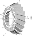
FIG. 2 is a perspective view of a gutter broom according to various aspects. -
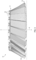
FIG. 3 is a side view of a gutter broom according to various aspects. -
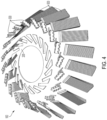
FIG. 4 is an exploded view of a gutter broom according to various aspects. -
FIG. 5 is a top view of a mandrel according to various aspects. -
FIG. 6 is a side view of a carrier according to various aspects. -
FIG. 7 is a perspective view of a portion of a gutter broom according to various aspects. -
FIG. 8 is a top view of a carrier according to various aspects. -
FIG. 9 is a side view of a bristle strip according to various aspects. -
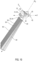
FIG. 10 is a perspective view of a carrier and bristle strip according to various aspects. -
FIG. 11 is a perspective view of a gutter broom according to various aspects. -
FIG. 12 is a perspective view of a carrier according to various aspects. -
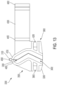
FIG. 13 is a side view of a carrier according to various aspects. -
FIG. 14 is a side view of a carrier according to various aspects. -
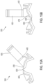
FIGS. 15A-B are front views of a carrier according to various aspects. -
FIG. 16 is a perspective view of a carrier according to various aspects. -
FIG. 17 is a perspective view of a bristle strip according to various aspects. -
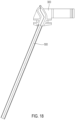
FIG. 18 is a side view of a carrier and bristle strip according to various aspects. -
FIG. 19 is an example method of assembling and maintaining a gutter broom, which does not form part of the invention. -
FIG. 20 is a perspective view of a gutter broom according to various aspects. -
FIG. 21 is a perspective view of a gutter broom according to various aspects. -
FIG. 22 is a perspective view of a gutter broom according to various aspects. - The features and advantages of the aspects will become more apparent from the detail description set forth below when taken in conjunction with the drawings, in which like reference characters identify corresponding elements throughout. In the drawings like reference numbers generally indicate identical, functionally similar, and/or structurally similar elements.
- The present invention will now be described in detail with reference to aspects thereof as illustrated in the accompanying drawings. References to "one aspect," "an aspect," "an exemplary aspect," etc., indicate that the aspect described may include a particular feature, structure, or characteristic, but every aspect may not necessarily include the particular feature, structure, or characteristic. Moreover, such phrases are not necessarily referring to the same aspect. Further, when a particular feature, structure, or characteristic is described in connection with an aspect, it is submitted that it is within the knowledge of one skilled in the art to affect such feature, structure, or characteristic in connection with other aspects whether or not explicitly described.
- The following examples are illustrative, but not limiting, of the present aspects. Other suitable modifications and adaptations of the variety of conditions and parameters normally encountered in the field, and which would be apparent to those skilled in the art, are within the scope of the disclosure.
- Aspects of the present disclosure discuss a gutter broom. The gutter broom can rotate around its central axis (i.e., its axis of rotation) to clean a surface along its path. The gutter broom, as described herein, includes a mandrel (i.e., a driven plate), one or more carriers, and one or more bristle strips (i.e., strips, broom segments, broom attachments, brush, bristles, etc.). The mandrel can be positioned approximately parallel to a horizontal direction and can rotate about a vertical axis. The mandrel can be circular or arced and can support approximately 20 bristle strips and carriers that extend downward from the mandrel. Each carrier is removably coupled to the mandrel in a channel extending through a radial outer end of the mandrel. The channel extends outwardly from a radial inner edge. The channel extends at an angle relative to a centerline of the mandrel. Detent tabs along the outer end of the mandrel can secure the carriers in the radial direction. Tabs along each side of the carriers can secure the carriers to the mandrel in the lateral direction. Each bristle strip can similarly be removably coupled to the mandrel and secured in both the radial and the lateral directions. Aspects provide that bristle strips can be inserted into the carriers and can be secured in the lateral and/or radial direction by, for example, a press fit, snap fit, interference fit, adhesive, a lock, or another attachment method.
- Roadway surfaces can be made of different materials (e.g., concrete, cobblestone, brick, etc.) and/or amass debris (e.g., growth, mud, non-natural debris, etc.), thus requiring cleaning applications that vary in contact pressure, time, or other parameters. In the gutter broom, bristle strips can extend down from the carriers to contact surfaces for cleaning. Aspects provide bristle strips that can be made of steel and/or another material (e.g., metals, plastics, composites, natural materials, etc.), and that can vary in dimensions, stiffness, geometry, or other properties for cleaning a variety of surfaces. For example, bristle strips can be composed of steel (e.g., steel wire). Steel can be sufficiently rigid to break down and/or move debris. Aspects provide that bristle strips can be composed of 100% recyclable steel. Accordingly, the gutter broom having recyclable steel bristle strips can be environmentally conscious. Other aspects provide that bristle strips can be composed of other materials, or a blend of materials. For example, a bristle strip can have a steel and polypropylene mix. In some aspects, the mandrel can also be composed of 100% recyclable steel. The carriers can be injection molded plastic in some aspects.
- The gutter broom described herein is modular. For example, the arrangement of the mandrel, carriers, and bristle strips can be modified both at initial assembly and during the life and operation of the gutter broom. Operators can customize the gutter broom to target the specific needs of a surface, e.g., by varying the number of bristle strips having specific characteristics. For example, a gutter broom can include a first type of bristle strips that provide fine contact and a second type of bristle strips that provide more aggressive contact. This can help to target surfaces having tough debris, such as growth, while also limiting the overall abrasive contact of the gutter broom so that roadway surfaces are not damaged. Modularity can also streamline assembly of the gutter broom and later replacement of the bristles. Instead of delivering a gutter broom that is at least partially assembled, which can increase packaging and delivery costs, modular components can be delivered compactly in fewer and smaller bundles (e.g., flat-packed or densely packed into two boxes).
- The modular components can be individually manufactured to support custom servicing. For example, if an operator requires a replacement carrier or bristle strip, they can source components instead of obtaining an entirely new gutter broom to acquire new parts. In some aspects, the gutter broom can cycle through many component replacements in its lifetime. Components can be individually sourced to replace damaged or worn components. Similarly, components can be exchanged between gutter brooms to support customization and servicing. In an aspect, modularity can also support the cleaning of each component to prevent contamination by, for example, mud or sand.
- Bristle strips can be arranged on the gutter broom in the carriers at an angle. In this way, each adjacent bristle strip can be offset. The angled arrangement of the bristle strips on the gutter broom can support distributed contact with a surface such that each bristle strip wears evenly as compared to other bristle strips assembled at the same time and having the same properties. A mandrel having a larger interior can also support this aspect. Because of the distributed wear, the bristle strips assembled at the same time and having the same properties can be replaced together. According to aspects, each bristle strip can last for approximately 80 to approximately 150 hours without needing servicing or replacement of the bristle strips.
- Servicing can also be simple such that no tools are required. For example, bristle strips can be positioned into carriers and easily removed in the same way, mechanically and without using tools. Accordingly, fewer and/or less skilled operators can assemble and service the gutter broom and replace worn bristle strips. Furthermore, assembly and replacement of bristle strips can occur in reduced time, e.g., minutes compared to hours. In some aspects, while the gutter broom is mounted onto a vehicle, a lock on each carrier can be opened, for example by pivoting the lock away from its locked position. This can allow radial movement of the bristle strips positioned in the carriers such that they can slide out of the carrier for replacement or servicing. Because the locks are simply pivoted away from their locked position to replace bristle strips, the gutter broom can remain mounted onto the vehicle during replacement. In this way, operators can easily complete replacement on the side of the road or a stopping area.
- The gutter broom described herein can additionally be efficiently manufactured because each component can be discretely produced and distributed. Further, including bristle strips of varying properties (e.g., stiffness) can reduce the weight of the gutter broom, which can support manufacturing efficiency. Increased manufacturing efficiency can significantly reduce the cost of the gutter broom. Cost savings can additionally progress beyond manufacturing; e.g., the lower weight of the gutter broom can support extended motor life and limited operating costs. Accordingly, bristle strip selection can be a function of surface type to both effectively clean and prevent damage from continuous abrasive contact, along with operating device motor considerations.
- A
gutter broom 100 is shown inFIGS. 1A-B . Whilegutter broom 100 is described herein, it is to be appreciated that its components can be used in other gutter brooms or gutter broom systems, e.g., for retrofit, customization by exchange of components, etc. - In some aspects,
gutter broom 100 can be mounted onto a vehicle 10 (e.g., a truck, tractor, or a compact vehicle). Vehicle 10 can guidegutter broom 100 along a variety of surfaces.Gutter broom 100 can be positioned at a side of vehicle 10 to move along curbs or the sides of buildings for cleaning (e.g., sweeping, debris and/or particulate matter removal, etc.) where debris can collect. Vehicle 10 can also movegutter broom 100 along floors in, for example, manufacturing areas or retail environments. Vehicle 10 can support a driver 12 and a drive plate 14. Driver 12 can rotate drive plate 14 andgutter broom 100 supported by drive plate 50 (e.g., via an electric or a hydraulic motor).Gutter broom 100 can rotate about its central axis 20 (i.e., its axis of rotation) to move and/or break down debris or other matter along its path (e.g., weeds, grass, mud, dirt, sand, trash, etc.).Central axis 20 can be generally perpendicular to the path along whichgutter broom 100 moves (e.g., surfaces to be cleaned). In an aspect,central axis 20 can be generally vertical.Gutter broom 100 can be positioned to be generally horizontal as it rotates about the generally verticalcentral axis 20. - As shown in
FIGS. 2-3 ,gutter broom 100 includes a mandrel 200 (i.e., a driven plate) that supports one ormore carriers 300 and one or more bristle strips 500 (i.e., strips, broom segments, broom attachments, brush, bristles, etc.). Eachcarrier 300 retains and supports abristle strip 500. In this way,carriers 300 can be sleeves or receptacles for bristle strips 500. -
Gutter broom 100 can have anupper end 101 and alower end 102.Upper end 101 ofgutter broom 100 can includemandrel 200, which can be fixedly attached to drive plate 14 (e.g., via bolts, adhesive, welding, etc.). In an aspect,mandrel 200 can be directly connected to broom driver 12 such that drive plate 14 is not needed. In some aspects,mandrel 200 can be removable such that it is modular.Lower end 102 ofgutter broom 100 can include bristlestrips 500 and can contact surfaces for cleaning. In an aspect,gutter broom 100 can be suspended from drive plate 14 such that onlylower end 102 ofgutter broom 100 can contact surfaces, debris, or other materials. - Bristle strips 500 can comprise material to withstand contact with various surfaces (e.g., concrete and unpaved roads) and debris (e.g., rocks, mud, growth, etc.). In an aspect, each bristle
strip 500 can comprise flattened steel wire folded over a steel cable to form the bristles. In some aspects, each bristlestrip 500 can include, for example, approximately fifteen to approximately thirty individual wires. The flattened steel wire and/or steel cable can further be encased in steel. In an aspect, the portion of each bristlestrip 500 that contacts surfaces can be the steel encasement such that the flattened steel wire does not contact surfaces or debris. In an aspect, the 100% steel composition of the bristle strips 500 can provide a stiffness that supports breaking down and movement of debris along the path ofgutter broom 100 while being fully recyclable.Bristle strip 500 will be described in further detail below. - With reference to
FIG. 4 , in some aspects,gutter broom 100 can support approximately 10 to approximately 35carriers 300 and bristlestrips 500, such as approximately 15 to approximately 30carriers 300 and bristlestrips 500, such as approximately 20carriers 300 and bristle strips 500. Eachcarrier 300 can be removably coupled togutter broom 100. Each bristlestrip 500 can be removably coupled to one of thecarriers 300 ongutter broom 100. In this way,carriers 300 and bristlestrips 500 can be modular. In another aspect,carriers 300 can be integrally formed withmandrel 200. In a further aspect,carriers 300 can be integrally formed with bristle strips 500. - As shown in
FIG. 5 ,mandrel 200 includes an interior 210, anouter end 220, one or more firstouter edges 230, one or more secondouter edges 240, one ormore channels 250, one or more channel ends 255, aninterior edge 260, aninner edge 270 ofouter end 220, atubular portion 280, and one or morecarrier detent tabs 290. - In some aspects,
mandrel 200 can be circular or arced. In an aspect,mandrel 200 can be of a standard size known in the industry. In some aspects,mandrel 200 can comprise one or more of metals, plastics, composites, ceramics, polymers, natural fibers, etc. For example,mandrel 200 can comprise steel. In an aspect,mandrel 200 can comprise 100% recyclable steel. - In some aspects, interior 210 can be defined by
interior edge 260.Interior edge 260 can be a radially interior edge ofmandrel 200 at a diameter D2 ofmandrel 200. Diameter D2 can be within a range of approximately 50 cm to approximately 127 cm.Outer end 220 can extend radially outwardly frominterior edge 260.Outer end 220 can include the one ormore channels 250. In some aspects, achannel 250 can be the opening between a firstouter edge 230 and a secondouter edge 240. Accordingly,outer end 220 can include one or more firstouter edges 230 and corresponding secondouter edges 240, with each firstouter edge 230 and secondouter edge 240 defining thechannels 250. In some aspects, firstouter edges 230 and secondouter edges 240 extend throughouter end 220. In some aspects, firstouter edges 230 and secondouter edges 240 extend radially outwardly from aninner edge 270 ofouter end 220. In an aspect,inner edge 270 can be a radial edge ofmandrel 200 at a diameter D1 ofmandrel 200. Diameter D1 can be within a range of approximately 50 cm to approximately 127 cm. -
Interior edge 260 andinner edge 270 can define atubular portion 280 ofmandrel 200. In some aspects,channels 250 are formed by attaching (e.g., by welding) pieces having firstouter edges 230 and secondouter edges 240 ontotubular portion 280 ofmandrel 200. Accordingly, in some aspects,mandrel 200 is not a unitary piece. In some aspects, acarrier detent tab 290 can extend into achannel 250 by extending from one or both of firstouter edge 230 and secondouter edge 240 intochannel 250. In some aspects, eachchannel 250 can extend from achannel end 255. Eachchannel end 255 can meet each firstouter edge 230 atinner edge 270 ofouter end 220. - In some aspects,
channel 250 can extend outwardly frominner edge 270 along achannel axis 16. In an aspect,channel axis 16 can be at a channel angle, θ, from acenterline 15 ofmandrel 200. In some aspects, the channel angle, θ, can range from approximately 5 degrees to approximately 85 degrees, such as approximately 20 degrees to approximately 60 degrees, such as approximately 30 degrees. In some aspects, the angled arrangement ofchannels 250 can reduce contact between adjacent bristle strips 500 while rotating such that bristlestrips 500 can be positioned to operate effectively. - In some aspects, interior 210, defined by
interior edge 260, can be sized to prevent bristlestrips 500 from bending inwardly while rotating ingutter broom 100 aroundcentral axis 20. In some aspects, interior 210 defined byinterior edge 260 can be sized to prevent each of bristle strips 500 from contacting any adjacent bristle strips 500 while rotating. For example, a larger interior 210 can allow for bristle strips 500 to be spaced farther apart such that contact between adjacent bristle strips 500 is reduced while rotating such that bristlestrips 500 can be positioned to operate effectively. - In some aspects, the distance between
interior edge 260 andinner edge 270 ofouter end 220 can be a distance D3, which is the difference between D1 and D2. This distance can definetubular portion 280 ofouter end 220. In some aspects, positioning bristlestrips 500 farther outwardly from interior 210 can distance adjacent bristle strips 500. Accordingly, in some aspects,tubular portion 280 betweeninterior edge 260 andinner edge 270 ofouter end 220 can reduce contact between adjacent bristle strips 500 while rotating such that bristlestrips 500 can be positioned to operate effectively. In some aspects,tubular portion 280 can supportouter end 220 and limit its lateral displacement (e.g., as a result of applied weight whenmandrel 200 is at least partially filled withcarriers 300 and bristle strips 500). - With reference to
FIGS. 6-7 , in some aspects, eachcarrier 300 includes afirst end 350, asecond end 360, leftrails 370,right rails 380, aleft slot 390, and aright slot 420. In some aspects,carrier 300 can include anupper end 310, alower end 320, an upper cavity 330, alower cavity 340, a lockingmember 430 and alock extension 440.Carriers 300 can be injection molded plastic, in some aspects. -
Carriers 300 are positioned inchannels 250 inmandrel 200 and removably coupled tomandrel 200 along firstouter edges 230 and secondouter edges 240. Eachcarrier 300 can be positioned at a channel angle θ fromcenterline 15. In an aspect, eachcarrier 300 can be positioned at the same channel angle θ. In another aspect,carriers 300 can be positioned at different channel angles θ. In an aspect, eachcarrier 300 can be arranged in achannel 250 such thatlower cavity 340 ofcarrier 300 can be oriented perpendicular to channel 250 such that bristlestrips 500 extend downward frommandrel 200 in a generally vertical direction. In another aspect, eachcarrier 300 can be arranged in achannel 250 such thatlower cavity 340 and or upper cavity 330 ofcarrier 300 can be oriented obliquely with respect to channel 250 such that bristlestrips 500 extend downward frommandrel 200 at an angle. For example,lower cavity 340 and or upper cavity 330 ofcarrier 300 can extend frommandrel 200 in a lateral direction generally parallel to an axis 22 (FIG. 6 ). In some aspects,axis 22 can be at an angle, α, fromaxis 21. Accordingly,carriers 300 can extend frommandrel 200 at an angle, α, fromaxis 21. In some aspects, the angle, α, can range from approximately 15 degrees to approximately 90 degrees, such as approximately 30 degrees to approximately 75 degrees, such as approximately 60 degrees. Accordingly, eachcarrier 300 can be arranged at an offset with respect to anadjacent carrier 300. - With reference to
FIG. 7 , in some aspects, acarrier 300 is positioned in achannel 250.Carrier detent tabs 290 can engage and retaincarrier 300 inchannel 250 in a radial direction generally parallel to anaxis 23. The engagement ofcarrier detent tabs 290 andcarrier 300 can create a snap fit or an interference fit to retaincarrier 300 inchannel 250. In some aspects,carrier detent tabs 290 onmandrel 200 can elastically deform a portion ofcarrier 300 inchannel 250 during installation, e.g., by pushing or slidingcarrier 300 overcarrier detent tabs 290 in a radial direction generally parallel to axis 23 (see alsoFIG. 10 ). Once engaged,carrier detent tabs 290 can prevent radial outward movement ofcarrier 300 fromchannel 250. - Each
carrier 300 includes left rails 370. The space betweenleft rails 370 defines leftslot 390. Similarly eachcarrier 300 includesright rails 380. The space betweenright rails 380 definesright slot 420.Carrier 300 can be disposed inchannel 250 and removably coupled tomandrel 200 such that firstouter edge 230 can be disposed inleft slot 390 betweenleft rails 370, and secondouter edge 240 can be disposed inright slot 420 betweenright rails 380. Accordingly,carrier 300 can surround firstouter edge 230 and secondouter edge 240 such thatcarrier 300 extends acrossmandrel 200 in a tangential direction generally parallel to an axis 21 (i.e., a length ofcarrier 300 is generally perpendicular to a radial edge of mandrel 200). In some aspects, leftrails 370 andright rails 380 can retaincarrier 300 inchannel 250 in a lateral direction generally parallel toaxis 22. In this way,carrier 300 can be maintained inchannel 250 in the lateral direction while rotating ingutter broom 100 aroundcentral axis 20 becauseleft rails 370 andright rails 380 can prevent lateral movement. -
Carriers 300 extend radially outward frommandrel 200. Eachcarrier 300 can be slidably arranged in achannel 250.Left slot 390 andright slot 420 allowcarrier 300 to slide over firstouter edge 230 and secondouter edge 240. In an aspect, pushing or slidingcarrier 300 overcarrier detent tabs 290 for approximately a distance D4 represents the extent to whichcarrier 300 can be radially disposed inchannel 250.Channel end 255 can provide an abutment at this most forward radial position ofcarrier 300 inchannel 250. With reference toFIG. 8 , in some aspects,first end 350 ofcarrier 300 can abut channelend 255 at this most forward radial position ofcarrier 300 inchannel 250. - As shown in
FIG. 8 , in some aspects, lockingmember 430 can be cantilevered. In an aspect, lockingmember 430 can have an attachedend 431 and afree end 432. In an aspect, attachedend 431 can secure lockingmember 430 to a surface ofcarrier 300.Free end 432 can be unattached and can extend away fromfirst end 350 ofcarrier 300 towardssecond end 360. In an aspect,free end 432 can include ridges and or knurling to allow a user to better gripfree end 432 during removal and installation of abristle strip 500. In some aspects,lock extension 440 of lockingmember 430 can extend transversally fromfree end 432. In this aspect,lock extension 440 can extend acrosssecond end 360 ofcarrier 300. Accordingly,lock extension 440 can extend acrosssecond end 360 in a tangential direction generally parallel to axis 21 (i.e.,lock extension 440 is positioned generally perpendicular tosecond end 360, which extends generally parallel to axis 22). In this way,lock extension 440 can prevent bristlestrip 500 positioned incarrier 300 from moving radially outwardly. Conversely,lock extension 440 can be pivoted away fromsecond end 360 to allow bristlestrip 500 to move radially outwardly, e.g., for servicing or replacement. - As shown in
FIG. 9 , abristle strip 500 can include anupper end 510, alower end 520, afirst end 530, asecond end 540, and aninsert 550. In some aspects, bristlestrip 500 can be manufactured continuously in a roll forming operation. - In some aspects, each bristle
strip 500 can include, for example, approximately fifteen to approximately thirty individual bristles. As discussed above, in an aspect, each bristlestrip 500 can include bristles folded over a cable. For example, thebristle strip 500 can comprise flattened steel wire folded over a steel cable. In some aspects, the bristles can be folded in half over a cable of approximately 13 cm (5 in) in length, In other aspects, the bristles can instead be folded over a composite "core" (i.e., a center mass). In an aspect, bristlestrip 500 can comprise bristles of approximately 13 cm (5 in) in length. In one aspect, individual bristles ofbristle strip 500 can be approximately 0.2 cm to approximately 0.4 cm wide, and approximately 0.05 cm to approximately 0.11 cm hardened spring steel. In another aspect, the bristles can be compacted cable between approximately 0.3 cm and approximately 1.2 cm in diameter. - The bristles and cable can further be encased, such as in steel. The encasement can be
insert 550. In some aspects, insert 500 can prevent bristles from contacting surfaces. In some aspects, the encasement forinsert 550 can be cut every six inches. In some aspects, the bristles can be wrapped in a steel casing that is approximately 0.05 cm to approximately 0.26 cm thick sheet steel. As discussed above, bristlestrip 500 can be 100% recyclable steel. In some aspects,upper end 510 of each bristlestrip 500 can have a larger cross-sectional area due to the cable. The larger cross-sectional area can allow bristlestrip 500 to fit tightly intoinsert 550. In an aspect,lower end 520 of each bristlestrip 500 can extend down fromupper end 510 and can be unattached (i.e., not coupled to any other component). In an aspect,lower end 520 can have a sharp leading edge to better move and/or break down debris along the path ofgutter broom 100. - In some aspects, bristle
strips 500 can comprise one or more of metals, plastics, composites, ceramics, polymers, natural fibers, etc. For example, bristlestrips 500 can comprise steel, aluminum, nylon, polyester, polypropylene, PVC, vegetable fibers, or hairs. Other aspects provide that bristle strips 500 can be composed of other materials, or a blend of materials. For example, abristle strip 500 can have a steel and polypropylene mix. In another aspect, the bristles can comprise polyurethane or other composite material that is approximately 0.1 cm to approximately 0.21 cm in diameter. In some aspects, the bristles can be round, and straight or crimped. - In some aspects, one or more bristle
strips 500 can have different properties based on the types of bristles contained inbristle strip 500. For example, including different types of bristle strips 500 having different properties ingutter broom 100 can advance and customize cleaning for one or more specific surfaces. For example, gutter brooms generally can be used outdoors to clean streets that require different types or levels of contact (e.g., abrasive or fine). Streets can vary in granularity and can be made from various materials, e.g., concrete, brick, cobblestone, and/or asphalt, each requiring different cleaning methods. Streets can also include growth, such as patches of grass or weeds. In another example, streets can have other natural debris, such as sand, mud, and rocks, or non-natural debris, such as trash and recyclables. Accordingly, cleaning bygutter broom 100 can be enhanced to effectively clean these distinct surfaces, growth, and/or debris.Gutter broom 100 can also be customized by including fewer bristle strips 500. For example, bristlestrips 500 can be omitted frommandrel 200 to create a paddle-type contact with surfaces, e.g., to clean around snow. In another aspect, bristlestrips 500 can vary in bristle length (e.g., bristles inbristle strip 500 can have different lengths), which can improve cleaning of intermediate surfaces. In this aspect, the surface contacting profile ofbristle strip 500 can be customized to clean one or more surfaces. - In some aspects,
gutter broom 100 can include bristlestrips 500 of different materials to advance and customize cleaning. In some aspects, bristlestrips 500 of different materials can be included ingutter broom 100 to leverage properties of each material. In other aspects, bristlestrips 500 can be blended, such as by including both steel and polypropylene. - In some aspects, bristle
strips 500 can vary in stiffness to advance and customize cleaning. For example, bristlestrips 500 having a greater stiffness can provide abrasive contact to better target certain debris, such as growth along streets and compacted mud. Accordingly, bristlestrips 500 can be useful for aggressive cleaning to target debris that can be tougher to move and/or break down (i.e., cut), such as growth, compacted mud, rocks, etc. The higher stiffness can reduce buckling and provide an inertial impact to move tougher debris. Bristle strips 500 having a higher stiffness that are arranged together (e.g., grouped or adjacently) can grip and/or break down tougher debris more effectively. Bristle strips 500 having a lower stiffness can provide can provide a finer contact. Accordingly, bristlestrips 500 can be useful for finer cleaning to target separations between various surfaces. Greater movement and flexibility can be realized at impact such that first bristle strips 500 can buckle to reach crevices, granularity, gaps, etc. Additionally, bristlestrips 500 can better target lighter debris (e.g., sand) and particulate matter. In some aspects,gutter broom 100 can include bristlestrips 500 having varying stiffness to provide both abrasive and fine contact with surfaces. Stiffness can be determined by material, diameter, cross-sectional area, cross-section geometry, wall thickness, outer layers, coatings for reinforcement, ribbing, elasticity openings, etc. For example, bristlestrips 500 comprising steel can be crimped to provide greater stiffness. Bristle strips 500 can have a cross-sectional geometry that is circular, elliptical, rectangular, or a star, plus sign, etc. - With reference to
FIGS. 9-10 , bristlestrips 500 can be removably coupled tocarriers 300, for example, by sliding bristle strips 500 intocarriers 300. In some aspects, each bristlestrip 500 can be arranged incarrier 300 such that bristlestrip 500 can also be oriented obliquely with respect tomandrel 200 andchannel 250. In some aspects, bristlestrips 500 can be pushed or slid intocarriers 300 in a radial direction generally parallel toaxis 23. Accordingly, similar tocarriers 300, when bristle strips 500 are removable coupled tocarriers 300, bristlestrips 500 can extend both upward and downward frommandrel 200 in a lateral direction generally parallel toaxis 22. In this way, bristlestrips 500 can extend frommandrel 200 at angle, α, fromaxis 21 such that each bristlestrip 500 can be arranged at an offset with respect to anadjacent bristle strip 500. The offset of each bristlestrip 500 can prevent each of bristle strips 500 from contacting anadjacent bristle strip 500 while rotating ingutter broom 100 aroundcentral axis 20. Additionally, as discussed above, in an aspect, because of the angled arrangement of bristle strips 500, asgutter broom 100 rotates aboutcentral axis 20, each bristlestrip 500 can wear more evenly. Because of the distributed wear, bristlestrips 500 having similar properties can require replacement at the same time. - With reference to
FIGS. 7 and10 , in some aspects,carrier 300 can be slidably arranged inchannel 250 by surrounding firstouter edge 230 and secondouter edge 240 ofmandrel 200.Carrier 300 can slide over firstouter edge 230 and secondouter edge 240 ofmandrel 200 such thatupper end 310 ofcarrier 300 can extend upward frommandrel 200 andlower end 320 ofcarrier 300 can extend downward frommandrel 200. In an aspect,upper end 310 ofcarrier 300 can include lockingmember 430. The space withinupper end 310 can include upper cavity 330.Lower end 320, can define the opposing end ofcarrier 300 fromupper end 310, and similarly can includelower cavity 340. - In some aspects, each of bristle strips 500 can be received within upper cavity 330 and
lower cavity 340 of one ofcarriers 300. In an aspect,upper end 510 ofbristle strip 500 can be received within upper cavity 330, andlower end 520 ofbristle strip 500 can be received withinlower cavity 340. - With reference to
FIGS. 9-10 , in an aspect,upper end 510, having a larger cross-sectional area, can fill upper cavity 330. This can create a press fit such thatupper end 510 can be secured within upper cavity 330 and, consequently, bristlestrip 500 can be secured incarrier 300. In other aspects, bristlestrip 500 can be secured incarrier 300 by snaps, adhesive, or another attachment method. In some aspects, bristlestrip 500 can be secured incarrier 300 such thatfirst end 530 ofbristle strip 500 can abutfirst end 350 ofcarrier 300, which, as discussed above, can abut channelend 255.Second end 540 can define the opposing end offirst end 530 and similarly abutsecond end 360 ofcarrier 300. In some aspects,upper end 510 ofbristle strip 500, having a larger cross-sectional area, can expand within upper cavity 330 ofcarrier 300 such that movement ofbristle strip 500 in a lateral direction generally parallel toaxis 22 can be prevented. In some aspects,lock extension 440 can extend acrossupper end 310 ofcarrier 300, and, consequently, upper cavity 330 ofcarrier 300. Accordingly, ifbristle strip 500 is secured incarrier 300,lock extension 440 can extend acrosssecond end 360 ofcarrier 300 andsecond end 540 ofbristle strip 500. This can prevent movement ofbristle strip 500 in a radial direction generally parallel toaxis 23. - As shown in
FIG. 11 in another example, in some aspects, agutter broom 1000 includes amandrel 2000 that can support one ormore carriers 3000 and one or more bristle strips 5000.Gutter broom 1000 and its components can be similar togutter broom 100 discussed above. - With reference to
FIGS. 12-13 , in some aspects, eachcarrier 3000 include aleft slot 3900, and aright slot 4200. In some aspects,carrier 3000 can include anupper end 3100, alower end 3200, anupper cavity 3300, alower cavity 3400, afirst end 3500, asecond end 3600, aleft side 4600, aright side 4700, acarrier hinge 4500, alock 4300, alock hinge 4400, alock end 4800, and alock tab 4900.Carriers 3000 can be injection molded plastic, in some aspects.Carriers 3000 can be removably coupled ontogutter broom 1000 similar tocarriers 300 ongutter broom 100. - With reference to
FIGS. 11 and14 , in some aspects,carriers 3000 can be oriented obliquely with respect tomandrel 2000. For example,carriers 3000 can extend upward in a lateral direction generally parallel to anaxis 25. In some aspects,axis 25 can be at an angle, β, fromaxis 24. Accordingly,carriers 3000 can extend upward frommandrel 2000 at an angle, β, fromaxis 24. Similarly,carriers 3000 can extend downward frommandrel 2000 in a lateral direction generally parallel to anaxis 26. In some aspects,axis 26 can be at an angle, γ, fromaxis 24. Accordingly,carriers 3000 can extend downward frommandrel 2000 at an angle, γ, fromaxis 24. In some aspects, the angle, β, and the angle, γ, fromaxis 24 can range from approximately 15 degrees to approximately 90 degrees, such as approximately 30 degrees to approximately 75 degrees, such as approximately 60 degrees. In this way,upper end 3100 andlower end 3200 of eachcarrier 3000 can be offset with respect to anadjacent carrier 3000upper end 3100 andlower end 3200, respectively. In some aspects,carrier 3000 can be disposed in channel 2500 and removably coupled tomandrel 2000 vialeft slot 3900 onleft side 4600 andright slot 4200 onright side 4700. In an aspect, leftslot 3900 andright slot 4200 can allowcarrier 3000 to slide overmandrel 2000. In some aspects,left side 4600 andright side 4700 surroundingmandrel 2000 disposed inleft slot 3900 andright slot 4200 can retaincarrier 300 in channel 2500 in a lateral direction generally parallel toaxis 25 oraxis 26. Accordingly,carrier 3000 can be maintained in channel 2500 in the lateral direction while rotating ingutter broom 1000. In other aspects,carrier 3000 can be coupled tomandrel 2000 by snaps, adhesive, or another attachment method. In an aspect,carrier 3000 can surroundmandrel 2000 such that it extends acrossmandrel 200 in a tangential direction generally parallel to an axis 24 (i.e., a length ofcarrier 3000 is generally perpendicular to a radial edge of mandrel 2000). - As shown in
FIGS. 15A-B , in some aspects,left side 4600 andright side 4700 can be hingedly attached to each other viacarrier hinge 4500. Accordingly,carrier 3000 can be a clamshell such that leftside 4600 andright side 4700 can pivot relative to each other. Due to manufacturing constraints, this hinged carrier can allow for more complex internal geometries to better couple tomandrel 2000 and/or bristlestrip 5000. In another aspect,carrier 3000 can be additively manufactured such thathinge 4500 is not necessary. - With reference to
FIGS. 11 and16 , to disposecarrier 3000 in channel 2500, leftside 4600 andright side 4700 can pivot inwardly abouthinge 4500 and slide overmandrel 2000 vialeft slot 3900 andright slot 4200. The inward pivot can allowcarrier 3000 to clear carrier detent tabs 2900 (seeFIG. 5 for carrier detent tabs 290) such thatfirst end 3500 ofcarrier 3000 can be radially inward of carrier detent tabs 2900 whencarrier 3000 is disposed in channel 2500. In some aspects,left side 4600 andright side 4700 can be biased to pivot outwardly. Accordingly, oncecarrier 3000 is disposed in channel 2500, leftside 4600 andright side 4700 can pivot outwardly and engage with carrier detent tabs 2900 vialeft slot 3900 andright slot 4200. The engagement can retaincarrier 3000 in channel 2500. In this way,carrier 3000 can be secured in a radial direction generally parallel toaxis 27. In some aspects,carriers 3000 can include an additional securing mechanism, such as a tab similar to carrier detent tabs 2900 that can contactmandrel 2000 and maintaincarrier 3000 in channel 2500. - With reference to
FIG. 14 , in some aspects,lock 4300 can extend acrosscarrier 3000 in a tangential direction generally parallel to axis 24 (i.e.,lock 4300 is positioned generally perpendicular tosecond end 3600, which extends generally parallel toaxes 25 and 26). In this way,lock 4300 can prevent bristlestrip 5000 positioned incarrier 3000 from moving radially outwardly. Conversely,lock 4300 can be pivoted away fromsecond end 3600 to allowbristle strip 5000 to move radially outwardly, e.g., for servicing or replacement. - With reference to
FIGS. 15A-16 , in this aspect,lock 4300 can extend acrosssecond end 3600 ofcarrier 3000, which can be at the opposite end ofcarrier 3000 fromfirst end 3500. In some aspects,lock end 4800 can engage withlock tab 4900 ofcarrier 3000 to securely close acrosssecond end 3600 ofcarrier 3000. In an aspect,lock end 4800 can be clipped or snapped ontolock tab 4900 of carrier 3000 (or otherwise latched). Because of the engagement betweenlock end 4800 andlock tab 4900,lock 4300 can be secured in a radial direction generally parallel toaxis 27. In an aspect,lock 4300 can pivot away fromsecond end 3600 ofcarrier 3000 via lock hinge 4400 (i.e.,lock 4300 can be released).Lock 4300 can be moved away fromsecond end 3600 ofcarrier 3000 at any time during the life ofgutter broom 1000, including whencarrier 3000 is coupled tomandrel 2000 and whengutter broom 1000 is mounted to and suspended from a vehicle (e.g., vehicle 10). In this way, bristlestrips 5000 can be accessed for replacement when needed. - As shown in
FIG. 17 , bristlestrip 5000 forgutter broom 1000 can be pre-folded (e.g., bent or curved prior to being inserted into carrier 3000). In this wayupper end 3100 andlower end 3200 can extend relative to each other such that bristlestrip 5000 does not extend generally alongaxis 25 oraxis 26 in its entirety. This geometry can increase friction betweenbristle strip 5000 andcarrier 3000 when bristlestrip 5000 is positioned incarrier 3000 for better retention ofbristle strip 5000 withincarrier 3000. - With reference to
FIGS. 11 and17-18 , bristlestrips 5000 can be removably coupled tocarriers 3000. In some aspects, each bristlestrip 5000 can be arranged incarrier 3000 such that bristlestrip 5000 can also be oriented obliquely with respect tomandrel 2000 and channel 2500. In some aspects, bristlestrips 5000 can be pushed or slid intocarriers 3000 in a radial direction generally parallel toaxis 27. Accordingly, similar tocarriers 3000, when bristle strips 5000 are removable coupled tocarriers 3000, bristlestrips 5000 can extend both upward and downward frommandrel 2000 in a lateral direction generally parallel toaxis 25 andaxis 26, respectively. Specifically,upper end 3100 ofcarrier 3000 can extend upward frommandrel 2000 andlower end 3200 ofcarrier 3000 can extend downward frommandrel 2000. In aspects, a portion ofbristle strips 5000 can extend frommandrel 2000 upward at angle, β, fromaxis 24, and another portion can extend downward at angle, γ, fromaxis 24. In this way, each bristlestrip 5000 can be arranged at an offset with respect to anadjacent bristle strip 5000. The offset of each bristlestrip 5000 can prevent each ofbristle strips 5000 from contacting any adjacent bristle strips 5000 while rotating ingutter broom 1000. - With reference to
FIGS. 16-18 , in an aspect,upper end 3100 ofcarrier 3000 can includelock 4300. The space withinupper end 3100 can includeupper cavity 3300.Lower end 3200, can define the opposing end ofcarrier 3000 fromupper end 3100, and similarly can includelower cavity 3400. In some aspects, each ofbristle strips 5000 can be received withinupper cavity 3300 andlower cavity 3400 of one ofcarriers 3000. In an aspect,upper end 5100 ofbristle strip 5000 can be received withinupper cavity 3300, andlower end 5200 ofbristle strip 5000 can be received withinlower cavity 3400. In an aspect, bristlestrip 5000 can be bent such that when bristlestrip 5000 is slid intocarrier 3000,upper end 3100 can fit the shape ofupper cavity 3300 andlower end 3200 can fit the shape oflower cavity 3400 such that bristlestrip 5000 can be press fit intocarrier 3000. Accordingly, movement ofbristle strip 5000 in a lateral direction generally parallel toaxis 25 oraxis 26 can be prevented. In this way, whenleft side 4600 andright side 4700 ofcarrier 3000 pivot outwardly to engage carrier detent tabs 2900,upper cavity 3300 andlower cavity 3400 can be shaped to receive and retain bristlestrip 5000. The friction between and geometry ofcarrier 3000 and bristlestrip 5000 can laterally retainbristle strip 5000. - In some aspects,
lock 4300 can extend acrosssecond end 3600 ofcarrier 3000, and, consequently,upper cavity 3300 ofcarrier 3000. Accordingly, ifbristle strip 5000 is secured incarrier 3000,lock 4300 can extend acrosssecond end 3600 ofcarrier 3000 andsecond end 5400 ofbristle strip 5000. This can prevent movement ofbristle strip 5000 in a radial direction generally parallel to axis 27 (FIG. 17 ). In some aspects,lock 4300 can completely extend acrosssecond end 3600 atupper cavity 3300 to prevent movement ofbristle strip 5000 in a radial direction generally parallel toaxis 27.Second end 3600 atupper cavity 3300 can be completely covered to retainbristle strip 5000. In other aspects, bristlestrip 5000 can be coupled tocarrier 3000 by snaps, adhesive, or another attachment method. - In some aspects,
lock 4300 can be pivoted away fromsecond end 3600 ofcarrier 3000 vialock hinge 4400. Accordingly, becauselock 4300 is not preventing movement ofbristle strip 5000 in a radial outward direction, bristlestrip 5000 can be removed fromcarrier 3000 for servicing or replacement. - An example method of assembly and replacement is shown in
FIG. 19 . The method, which does not form part of the claimed invention, will be described particularly with reference togutter broom 100, however, it will be appreciated that the method can be applied togutter broom 1000, as well as other gutter brooms contemplated. - For initial assembly, an operator can receive modular components of
gutter broom 100, includingmandrel 200,carriers 300, and bristle strips 500. Due to their generally flat shape, bristlestrips 500 can be efficiently packaged and shipped. Bristle strips 500 can be received according to the operator's needs. For example, the operator can require bristlestrips 500 comprising steel wire and/or polypropylene and receive bristlestrips 500 accordingly. - To initially assemble
gutter broom 100, the operator can slide one ormore carriers 300 ontomandrel 200, as shown instep 1910. The operator can repeat this step for each of up to approximately 30carriers 300. Forgutter broom 1000, this step can include pivotingcarriers 3000 inward and sliding them ontomandrel 2000. Once carrier detent tabs 2900 are cleared,carriers 3000 can be pivoted outward toward their biased position to engage with carrier detent tabs 2900 and secure ontomandrel 2000. Instep 1920, the operator can slide one or more bristlestrips 500 into the one ormore carriers 300. The operator can repeat this step for as many carriers, such as up to approximately 20carriers mandrel 200. Assembly and servicing can additionally be simple, requiring no tools. Afull gutter broom 100 can be seen inFIG. 20 . - As shown in
FIG. 19 , instep 1930, the operator can the remove at least one bristlestrip 500. This can be to replace or repair bristlestrips 500, or to better adaptgutter broom 100 to a particular surface, e.g., to provide a less abrasive contact. To remove bristlestrips 500, the operator can push the cantilevered lockingmember 430 aside and slide out bristlestrip 500.Second end 360 ofcarrier 300 can be open such that bristlestrip 500 can be slid out when lockingmember 430 is pushed aside.Gutter broom 100 with abristle strip 500 removed can be seen inFIG. 21 . Forgutter broom 1000,lock 4300 can be pivoted away fromsecond end 3600 ofcarrier 3000 by unclippinglock end 4800 fromlock tab 4900 of carrier 3000 (i.e., releasing lock 4300).Bristle strip 5000 can be slid out oncelock 4300 is cleared fromsecond end 3600 ofcarrier 3000. As discussed above, asgutter broom 100 rotates aboutcentral axis 20, each bristlestrip 500 can wear more evenly. Because of the distributed wear, bristlestrips 500 having the same properties and that are assembled together can require replacement at the same time. - In an aspect, steps 1920 and 1930 can be performed more regularly than
steps gutter broom 100. Thus, replacement of bristle strips 500 is considered to be high frequency maintenance, while replacement ofcarriers 300 is considered to be low frequency maintenance. - In some aspects, bristle
strip 500 can be removably coupled tocarrier 300 prior tocarrier 300 being removably coupled tomandrel 200 and disposed inchannel 250 ofmandrel 200.Bristle strip 500 can alternatively be removably coupled tocarrier 300 oncecarrier 300 is removably coupled tomandrel 200 and disposed inchannel 250. Accordingly, bristlestrip 500 can be removed fromcarrier 300 both before and aftercarrier 300 is removably coupled tomandrel 200 and disposed inchannel 250. - Typically, only bristle
strips 500 need to be replaced due to wear, but occasionallycarrier 300 might need to be replaced due to damage or wear. As shown inFIG. 19 , instep 1940, the operator can remove at least onecarrier 300 that receives abristle strip 500.Carrier 300 cannot be removed while it contains abristle strip 500. So bristle strip 500 (step 1930) must be removed prior to removing carrier 300 (step 1940). To removecarriers 300, the operator can slidecarriers 300 over firstouter edges 230 and secondouter edges 240, including overcarrier detent tabs 290 for approximately a distance D4 (FIG. 7 ).Gutter broom 100 with acarrier 300 removed can be seen inFIG. 22 . In some aspects,carrier 300 can be removed frommandrel 200 whilebristle strip 500 is removably coupled tocarrier 300. Accordingly,carrier 300 and abristle strip 500 received incarrier 300 can be removed frommandrel 200 at once. - In an aspect,
carrier 300 can contact surfaces and/or debris with less frequency than bristlestrip 500. Accordingly, in an aspect,carrier 300 can have a lower replacement frequency than bristlestrip 500. In an aspect,mandrel 200 can have a lower replacement frequency than bothcarrier 300 and bristlestrip 500.Mandrel 200 and/orcarrier 300 can be replaced if either experiences significant damage or wear. Replacement ofmandrel 200,carrier 300, and/or bristlestrip 500 can also require no tools. - It is to be appreciated that the Detailed Description section, and not the Summary and Abstract sections, is intended to be used to interpret the claims.
- The present invention has been described above with the aid of functional building blocks illustrating the implementation of specified functions and relationships thereof. The boundaries of these functional building blocks have been arbitrarily defined herein for the convenience of the description. Alternate boundaries can be defined so long as the specified functions and relationships thereof are appropriately performed.
- The foregoing description of the specific aspects will so fully reveal the general nature of the invention that others can, by applying knowledge within the skill of the art, readily modify and/or adapt for various applications such specific aspects, without undue experimentation, without departing from the general concept of the present invention. Therefore, such adaptations and modifications are intended to be within the scope of the invention, based on the teaching and guidance presented herein. It is to be understood that the phraseology or terminology herein is for the purpose of description and not of limitation, such that the terminology or phraseology of the present specification is to be interpreted by the skilled artisan in light of the teachings and guidance.
- The breadth and scope of the present invention should not be limited by any of the above-described exemplary aspects, but should be defined only in accordance with the following claims.
Claims (11)
- A gutter broom (100), comprising:a mandrel (200) including a channel (250) that extends outwardly from an inner radial edge (270) at a non-zero angle relative to a centerline (15) of the mandrel (200);a retaining carrier (300) positioned in the channel (250) and coupled to the mandrel (200), the retaining carrier (300) comprising a left slot (390) and a right slot (420) to receive the mandrel (200); anda bristle strip (500) coupled to the carrier (300) such that it is retained, the bristle strip (500) extending down from the carrier (300).
- The gutter broom (100) of claim 1, wherein the bristle strip (500) comprises:a cable; andbristles folded around the cable.
- The gutter broom (100) of claim 2, wherein the cable is positioned within a cavity of the carrier (300) to couple the bristle strip (500) to the carrier (300).
- The gutter broom (100) of claim 1, wherein the bristle strip (500) comprises an upper end (510) having a first cross-sectional area and a lower end (520) having a second cross-sectional area, the first cross-sectional area greater than the second cross-sectional area.
- The gutter broom (100) of claim 4, wherein the bristle strip (500) is coupled to the carrier (300) at the upper end (510).
- The gutter broom (100) of claim 1, wherein the carrier (300) is oriented obliquely with respect to the channel (250).
- The gutter broom (100) of claim 1, wherein the carrier (300) comprises a lock (430) to retain the bristle strip (500).
- The gutter broom of claim 7, wherein the lock includes a cantilevered portion.
- The gutter broom (100) of claim 7, wherein the lock (430) extends across one or more sides of the carrier (300).
- The gutter broom (100) of claim 7, wherein the lock (430) prevents radial outward movement of the bristle strip (500) coupled to the carrier (300).
- The gutter broom (100) of claim 1, wherein the angle is 30 degrees.
Applications Claiming Priority (2)
| Application Number | Priority Date | Filing Date | Title |
|---|---|---|---|
| US202063116263P | 2020-11-20 | 2020-11-20 | |
| PCT/US2021/060121 WO2022109290A1 (en) | 2020-11-20 | 2021-11-19 | Gutter broom |
Publications (2)
| Publication Number | Publication Date |
|---|---|
| EP4247213A1 EP4247213A1 (en) | 2023-09-27 |
| EP4247213B1 true EP4247213B1 (en) | 2025-07-09 |
Family
ID=79025049
Family Applications (1)
| Application Number | Title | Priority Date | Filing Date |
|---|---|---|---|
| EP21831144.7A Active EP4247213B1 (en) | 2020-11-20 | 2021-11-19 | Gutter broom |
Country Status (9)
| Country | Link |
|---|---|
| US (3) | US11523676B2 (en) |
| EP (1) | EP4247213B1 (en) |
| JP (1) | JP7830465B2 (en) |
| CN (1) | CN116568180A (en) |
| AU (1) | AU2021383822A1 (en) |
| CA (1) | CA3197785A1 (en) |
| ES (1) | ES3037934T3 (en) |
| MX (1) | MX2023005898A (en) |
| WO (1) | WO2022109290A1 (en) |
Families Citing this family (3)
| Publication number | Priority date | Publication date | Assignee | Title |
|---|---|---|---|---|
| JP2024519914A (en) * | 2021-05-27 | 2024-05-21 | ザ マリッシュ コーポレイション | Abrasive Brush System |
| CN116728459B (en) * | 2023-06-29 | 2025-12-12 | 中山大学 | A biomimetic multi-linkage irregular bristle filter hand and robotic arm |
| US20250031932A1 (en) * | 2023-07-29 | 2025-01-30 | Keystone Plastics Inc. | Brush Assembly |
Citations (1)
| Publication number | Priority date | Publication date | Assignee | Title |
|---|---|---|---|---|
| US2565047A (en) * | 1946-08-12 | 1951-08-21 | Fuller Brush Co | Brush with flat wire elements |
Family Cites Families (23)
| Publication number | Priority date | Publication date | Assignee | Title |
|---|---|---|---|---|
| US2923958A (en) * | 1960-02-09 | lechene | ||
| GB859157A (en) * | 1959-11-02 | 1961-01-18 | Leo Leon Leohene | Street gutter broom |
| US3243832A (en) | 1963-11-15 | 1966-04-05 | Electrolux Corp | Rotary brush |
| DE8009273U1 (en) * | 1980-04-03 | 1980-07-31 | Jakob Reislaender Kg, Fabrik Techn. Buersten, 8000 Muenchen | PLATE BROOMS AS RECEIVER OR GUTTER BRUSHES FOR STREET SWEEPERS |
| US4409702A (en) | 1981-06-12 | 1983-10-18 | Milliken Research Corporation | Universal brush plate assembly |
| DE8718053U1 (en) | 1987-04-02 | 1993-03-04 | Jakob Reisländer Fabrik technischer Bürsten GmbH, 8000 München | Disc brushes, especially gutter brushes for street sweepers |
| FR2614188A1 (en) | 1987-04-27 | 1988-10-28 | Rozier Henry | Cleaning brush, particularly for a vehicle such as a road sweeper |
| US5045091A (en) * | 1987-06-26 | 1991-09-03 | Minnesota Mining And Manufacturing Company | Method of making rotary brush with removable brush elements |
| US5445438A (en) * | 1991-10-17 | 1995-08-29 | Drumm; Arthur E. | Strip brush for mounting on a rotary drum |
| US5438728A (en) | 1994-03-18 | 1995-08-08 | Minnesota Mining And Manufacturing Company | Rotary brush with segmented fiber sections |
| CA2141528A1 (en) * | 1995-01-25 | 1996-07-26 | Frances Gould | Broom having improved brush arrangement |
| US6026533A (en) | 1997-05-13 | 2000-02-22 | Prohoroff; Phillip W. | Rotary brush plate apparatus |
| NL1021923C2 (en) | 2002-11-14 | 2004-05-17 | Clemens Jacobus Franc Jorissen | Brushing device and method for manufacturing a brushing device. |
| FI114966B (en) * | 2003-04-03 | 2005-02-15 | Sajakorpi Oy | Dish Brush |
| EP1623652A1 (en) | 2004-07-23 | 2006-02-08 | Koti Onroerend Goed b.v. | Rotating disc-shaped brush for sweeping machines |
| CN2858763Y (en) | 2006-01-19 | 2007-01-17 | 刘晓贤 | Rotary type road brush cleaner and cleaning device thereof |
| JP2009108632A (en) * | 2007-10-31 | 2009-05-21 | Kowa Co Ltd | Rotating brush for road sweeper and road sweeper |
| JP2009131386A (en) * | 2007-11-29 | 2009-06-18 | Kowa Co Ltd | Side brush for road sweeper and road sweeper |
| GB2465381A (en) * | 2008-11-14 | 2010-05-19 | Applied Sweepers Ltd | Rotary brush |
| DK177159B1 (en) * | 2009-05-18 | 2012-03-05 | Poul Erik Jespersen | Grinding head, adapter list and use of an adapter list |
| ES2395270B1 (en) | 2011-02-08 | 2013-12-20 | Juan Ignacio MARTÍNEZ BARAGAÑO | BRUSH FOR ROAD SWEEPERS WITH REPLACABLE RUBBER OR POLYURETHANE SWEEP SHEETS. |
| WO2016043152A1 (en) | 2014-09-17 | 2016-03-24 | コニカミノルタ株式会社 | Brush for sunlight-reflection mirror, and method and device for cleaning sunlight-reflection mirror |
| US10188201B1 (en) * | 2014-10-14 | 2019-01-29 | Gordon Brush Mfg. Co., Inc. | Broom |
-
2021
- 2021-11-19 WO PCT/US2021/060121 patent/WO2022109290A1/en not_active Ceased
- 2021-11-19 MX MX2023005898A patent/MX2023005898A/en unknown
- 2021-11-19 ES ES21831144T patent/ES3037934T3/en active Active
- 2021-11-19 AU AU2021383822A patent/AU2021383822A1/en active Pending
- 2021-11-19 US US17/531,001 patent/US11523676B2/en active Active
- 2021-11-19 JP JP2023530802A patent/JP7830465B2/en active Active
- 2021-11-19 CA CA3197785A patent/CA3197785A1/en active Pending
- 2021-11-19 CN CN202180078105.7A patent/CN116568180A/en active Pending
- 2021-11-19 EP EP21831144.7A patent/EP4247213B1/en active Active
-
2022
- 2022-12-09 US US18/064,041 patent/US11759004B2/en active Active
-
2023
- 2023-06-07 US US18/330,977 patent/US12029312B2/en active Active
Patent Citations (1)
| Publication number | Priority date | Publication date | Assignee | Title |
|---|---|---|---|---|
| US2565047A (en) * | 1946-08-12 | 1951-08-21 | Fuller Brush Co | Brush with flat wire elements |
Also Published As
| Publication number | Publication date |
|---|---|
| ES3037934T3 (en) | 2025-10-08 |
| US20230172350A1 (en) | 2023-06-08 |
| CN116568180A (en) | 2023-08-08 |
| EP4247213A1 (en) | 2023-09-27 |
| US11759004B2 (en) | 2023-09-19 |
| US12029312B2 (en) | 2024-07-09 |
| AU2021383822A1 (en) | 2023-06-22 |
| US20220160118A1 (en) | 2022-05-26 |
| CA3197785A1 (en) | 2022-05-27 |
| JP7830465B2 (en) | 2026-03-16 |
| JP2023550478A (en) | 2023-12-01 |
| US20230309683A1 (en) | 2023-10-05 |
| US11523676B2 (en) | 2022-12-13 |
| MX2023005898A (en) | 2023-08-28 |
| WO2022109290A1 (en) | 2022-05-27 |
Similar Documents
| Publication | Publication Date | Title |
|---|---|---|
| US12029312B2 (en) | Gutter broom | |
| USRE50797E1 (en) | Cable broom | |
| KR101257308B1 (en) | A broom brush | |
| CA2176090C (en) | Vehicle-mountable push broom | |
| EP0265407B1 (en) | Motor driven brush assembly for a vacuum cleaner | |
| US10244859B2 (en) | Broom attachment, broom assembly and method for use thereof | |
| CA2262470C (en) | Brush ring | |
| US20040019992A1 (en) | Agitator construction | |
| EP0855156A2 (en) | Tesselated cylindrical brush | |
| HK40098245A (en) | Gutter broom | |
| WO1991004691A1 (en) | Brush roller for a street sweeper | |
| EP1266590A2 (en) | Modular roller for industrial rotary cylindrical brushes, particularly for outdoor use | |
| WO2026076371A1 (en) | Gutter broom | |
| KR200379211Y1 (en) | Roller-brush for street cleaning car | |
| US4375116A (en) | Vehicle washing brush | |
| EP1428456B1 (en) | Roller for rotating cylindrical brushes applicable in any industrial, road-related or other sector | |
| CA2928328A1 (en) | Broom attachment, broom assembly and method for use thereof | |
| RU2344736C2 (en) | Plate brush fabrication method and plate brush proper | |
| EP2532788A2 (en) | A brush assembly | |
| EP0140852A2 (en) | Brush-holder element | |
| KR20220001932U (en) | Brush module for street cleaning vehicle | |
| WO2025029699A1 (en) | Brush assembly | |
| CN110387852B (en) | Anti-breaking efficient snow sweeping brush | |
| CA2141528A1 (en) | Broom having improved brush arrangement | |
| KR20110022782A (en) | Broom Brush for Cleaning Cars |
Legal Events
| Date | Code | Title | Description |
|---|---|---|---|
| STAA | Information on the status of an ep patent application or granted ep patent |
Free format text: STATUS: UNKNOWN |
|
| STAA | Information on the status of an ep patent application or granted ep patent |
Free format text: STATUS: THE INTERNATIONAL PUBLICATION HAS BEEN MADE |
|
| PUAI | Public reference made under article 153(3) epc to a published international application that has entered the european phase |
Free format text: ORIGINAL CODE: 0009012 |
|
| STAA | Information on the status of an ep patent application or granted ep patent |
Free format text: STATUS: REQUEST FOR EXAMINATION WAS MADE |
|
| 17P | Request for examination filed |
Effective date: 20230615 |
|
| AK | Designated contracting states |
Kind code of ref document: A1 Designated state(s): AL AT BE BG CH CY CZ DE DK EE ES FI FR GB GR HR HU IE IS IT LI LT LU LV MC MK MT NL NO PL PT RO RS SE SI SK SM TR |
|
| DAV | Request for validation of the european patent (deleted) | ||
| DAX | Request for extension of the european patent (deleted) | ||
| STAA | Information on the status of an ep patent application or granted ep patent |
Free format text: STATUS: EXAMINATION IS IN PROGRESS |
|
| 17Q | First examination report despatched |
Effective date: 20240524 |
|
| GRAP | Despatch of communication of intention to grant a patent |
Free format text: ORIGINAL CODE: EPIDOSNIGR1 |
|
| STAA | Information on the status of an ep patent application or granted ep patent |
Free format text: STATUS: GRANT OF PATENT IS INTENDED |
|
| INTG | Intention to grant announced |
Effective date: 20250214 |
|
| RAP3 | Party data changed (applicant data changed or rights of an application transferred) |
Owner name: OLD DOMINION BRUSH COMPANY |
|
| GRAS | Grant fee paid |
Free format text: ORIGINAL CODE: EPIDOSNIGR3 |
|
| GRAA | (expected) grant |
Free format text: ORIGINAL CODE: 0009210 |
|
| STAA | Information on the status of an ep patent application or granted ep patent |
Free format text: STATUS: THE PATENT HAS BEEN GRANTED |
|
| AK | Designated contracting states |
Kind code of ref document: B1 Designated state(s): AL AT BE BG CH CY CZ DE DK EE ES FI FR GB GR HR HU IE IS IT LI LT LU LV MC MK MT NL NO PL PT RO RS SE SI SK SM TR |
|
| REG | Reference to a national code |
Ref country code: GB Ref legal event code: FG4D |
|
| REG | Reference to a national code |
Ref country code: CH Ref legal event code: EP |
|
| REG | Reference to a national code |
Ref country code: IE Ref legal event code: FG4D |
|
| REG | Reference to a national code |
Ref country code: DE Ref legal event code: R096 Ref document number: 602021033928 Country of ref document: DE |
|
| P01 | Opt-out of the competence of the unified patent court (upc) registered |
Free format text: CASE NUMBER: UPC_APP_0002_4247213/2025 Effective date: 20250708 |
|
| REG | Reference to a national code |
Ref country code: ES Ref legal event code: FG2A Ref document number: 3037934 Country of ref document: ES Kind code of ref document: T3 Effective date: 20251008 |
|
| PGFP | Annual fee paid to national office [announced via postgrant information from national office to epo] |
Ref country code: FR Payment date: 20250909 Year of fee payment: 5 |
|
| REG | Reference to a national code |
Ref country code: NL Ref legal event code: MP Effective date: 20250709 |
|
| PG25 | Lapsed in a contracting state [announced via postgrant information from national office to epo] |
Ref country code: PT Free format text: LAPSE BECAUSE OF FAILURE TO SUBMIT A TRANSLATION OF THE DESCRIPTION OR TO PAY THE FEE WITHIN THE PRESCRIBED TIME-LIMIT Effective date: 20251110 |
|
| PG25 | Lapsed in a contracting state [announced via postgrant information from national office to epo] |
Ref country code: NL Free format text: LAPSE BECAUSE OF FAILURE TO SUBMIT A TRANSLATION OF THE DESCRIPTION OR TO PAY THE FEE WITHIN THE PRESCRIBED TIME-LIMIT Effective date: 20250709 |
|
| REG | Reference to a national code |
Ref country code: AT Ref legal event code: MK05 Ref document number: 1810974 Country of ref document: AT Kind code of ref document: T Effective date: 20250709 |
|
| PG25 | Lapsed in a contracting state [announced via postgrant information from national office to epo] |
Ref country code: IS Free format text: LAPSE BECAUSE OF FAILURE TO SUBMIT A TRANSLATION OF THE DESCRIPTION OR TO PAY THE FEE WITHIN THE PRESCRIBED TIME-LIMIT Effective date: 20251109 |
|
| PGFP | Annual fee paid to national office [announced via postgrant information from national office to epo] |
Ref country code: DE Payment date: 20251118 Year of fee payment: 5 |
|
| PGFP | Annual fee paid to national office [announced via postgrant information from national office to epo] |
Ref country code: GB Payment date: 20251002 Year of fee payment: 5 |
|
| PG25 | Lapsed in a contracting state [announced via postgrant information from national office to epo] |
Ref country code: NO Free format text: LAPSE BECAUSE OF FAILURE TO SUBMIT A TRANSLATION OF THE DESCRIPTION OR TO PAY THE FEE WITHIN THE PRESCRIBED TIME-LIMIT Effective date: 20251009 |
|
| REG | Reference to a national code |
Ref country code: LT Ref legal event code: MG9D |
|
| PG25 | Lapsed in a contracting state [announced via postgrant information from national office to epo] |
Ref country code: AT Free format text: LAPSE BECAUSE OF FAILURE TO SUBMIT A TRANSLATION OF THE DESCRIPTION OR TO PAY THE FEE WITHIN THE PRESCRIBED TIME-LIMIT Effective date: 20250709 |
|
| PG25 | Lapsed in a contracting state [announced via postgrant information from national office to epo] |
Ref country code: FI Free format text: LAPSE BECAUSE OF FAILURE TO SUBMIT A TRANSLATION OF THE DESCRIPTION OR TO PAY THE FEE WITHIN THE PRESCRIBED TIME-LIMIT Effective date: 20250709 |
|
| PGFP | Annual fee paid to national office [announced via postgrant information from national office to epo] |
Ref country code: IT Payment date: 20251009 Year of fee payment: 5 |
|
| PG25 | Lapsed in a contracting state [announced via postgrant information from national office to epo] |
Ref country code: HR Free format text: LAPSE BECAUSE OF FAILURE TO SUBMIT A TRANSLATION OF THE DESCRIPTION OR TO PAY THE FEE WITHIN THE PRESCRIBED TIME-LIMIT Effective date: 20250709 |
|
| PG25 | Lapsed in a contracting state [announced via postgrant information from national office to epo] |
Ref country code: GR Free format text: LAPSE BECAUSE OF FAILURE TO SUBMIT A TRANSLATION OF THE DESCRIPTION OR TO PAY THE FEE WITHIN THE PRESCRIBED TIME-LIMIT Effective date: 20251010 |
|
| PG25 | Lapsed in a contracting state [announced via postgrant information from national office to epo] |
Ref country code: SE Free format text: LAPSE BECAUSE OF FAILURE TO SUBMIT A TRANSLATION OF THE DESCRIPTION OR TO PAY THE FEE WITHIN THE PRESCRIBED TIME-LIMIT Effective date: 20250709 |
|
| PG25 | Lapsed in a contracting state [announced via postgrant information from national office to epo] |
Ref country code: LV Free format text: LAPSE BECAUSE OF FAILURE TO SUBMIT A TRANSLATION OF THE DESCRIPTION OR TO PAY THE FEE WITHIN THE PRESCRIBED TIME-LIMIT Effective date: 20250709 |
|
| PG25 | Lapsed in a contracting state [announced via postgrant information from national office to epo] |
Ref country code: PL Free format text: LAPSE BECAUSE OF FAILURE TO SUBMIT A TRANSLATION OF THE DESCRIPTION OR TO PAY THE FEE WITHIN THE PRESCRIBED TIME-LIMIT Effective date: 20250709 Ref country code: BG Free format text: LAPSE BECAUSE OF FAILURE TO SUBMIT A TRANSLATION OF THE DESCRIPTION OR TO PAY THE FEE WITHIN THE PRESCRIBED TIME-LIMIT Effective date: 20250709 |
|
| PG25 | Lapsed in a contracting state [announced via postgrant information from national office to epo] |
Ref country code: RS Free format text: LAPSE BECAUSE OF FAILURE TO SUBMIT A TRANSLATION OF THE DESCRIPTION OR TO PAY THE FEE WITHIN THE PRESCRIBED TIME-LIMIT Effective date: 20251009 |
|
| PGFP | Annual fee paid to national office [announced via postgrant information from national office to epo] |
Ref country code: ES Payment date: 20251201 Year of fee payment: 5 |
|
| PG25 | Lapsed in a contracting state [announced via postgrant information from national office to epo] |
Ref country code: RO Free format text: LAPSE BECAUSE OF FAILURE TO SUBMIT A TRANSLATION OF THE DESCRIPTION OR TO PAY THE FEE WITHIN THE PRESCRIBED TIME-LIMIT Effective date: 20250709 |
|
| PG25 | Lapsed in a contracting state [announced via postgrant information from national office to epo] |
Ref country code: SM Free format text: LAPSE BECAUSE OF FAILURE TO SUBMIT A TRANSLATION OF THE DESCRIPTION OR TO PAY THE FEE WITHIN THE PRESCRIBED TIME-LIMIT Effective date: 20250709 |
|
| PG25 | Lapsed in a contracting state [announced via postgrant information from national office to epo] |
Ref country code: DK Free format text: LAPSE BECAUSE OF FAILURE TO SUBMIT A TRANSLATION OF THE DESCRIPTION OR TO PAY THE FEE WITHIN THE PRESCRIBED TIME-LIMIT Effective date: 20250709 |
|
| PG25 | Lapsed in a contracting state [announced via postgrant information from national office to epo] |
Ref country code: CZ Free format text: LAPSE BECAUSE OF FAILURE TO SUBMIT A TRANSLATION OF THE DESCRIPTION OR TO PAY THE FEE WITHIN THE PRESCRIBED TIME-LIMIT Effective date: 20250709 |
|
| PG25 | Lapsed in a contracting state [announced via postgrant information from national office to epo] |
Ref country code: SK Free format text: LAPSE BECAUSE OF FAILURE TO SUBMIT A TRANSLATION OF THE DESCRIPTION OR TO PAY THE FEE WITHIN THE PRESCRIBED TIME-LIMIT Effective date: 20250709 Ref country code: EE Free format text: LAPSE BECAUSE OF FAILURE TO SUBMIT A TRANSLATION OF THE DESCRIPTION OR TO PAY THE FEE WITHIN THE PRESCRIBED TIME-LIMIT Effective date: 20250709 |
|
| PLBE | No opposition filed within time limit |
Free format text: ORIGINAL CODE: 0009261 |
|
| STAA | Information on the status of an ep patent application or granted ep patent |
Free format text: STATUS: NO OPPOSITION FILED WITHIN TIME LIMIT |