EP4247125A1 - Electronic device having floating support structure - Google Patents
Electronic device having floating support structure Download PDFInfo
- Publication number
- EP4247125A1 EP4247125A1 EP21896250.4A EP21896250A EP4247125A1 EP 4247125 A1 EP4247125 A1 EP 4247125A1 EP 21896250 A EP21896250 A EP 21896250A EP 4247125 A1 EP4247125 A1 EP 4247125A1
- Authority
- EP
- European Patent Office
- Prior art keywords
- circuit board
- electronic component
- floating support
- electronic device
- assembly
- Prior art date
- Legal status (The legal status is an assumption and is not a legal conclusion. Google has not performed a legal analysis and makes no representation as to the accuracy of the status listed.)
- Pending
Links
Images


Classifications
-
- H—ELECTRICITY
- H05—ELECTRIC TECHNIQUES NOT OTHERWISE PROVIDED FOR
- H05K—PRINTED CIRCUITS; CASINGS OR CONSTRUCTIONAL DETAILS OF ELECTRIC APPARATUS; MANUFACTURE OF ASSEMBLAGES OF ELECTRICAL COMPONENTS
- H05K7/00—Constructional details common to different types of electric apparatus
- H05K7/20—Modifications to facilitate cooling, ventilating, or heating
- H05K7/20845—Modifications to facilitate cooling, ventilating, or heating for automotive electronic casings
- H05K7/20854—Heat transfer by conduction from internal heat source to heat radiating structure
-
- H—ELECTRICITY
- H05—ELECTRIC TECHNIQUES NOT OTHERWISE PROVIDED FOR
- H05K—PRINTED CIRCUITS; CASINGS OR CONSTRUCTIONAL DETAILS OF ELECTRIC APPARATUS; MANUFACTURE OF ASSEMBLAGES OF ELECTRICAL COMPONENTS
- H05K1/00—Printed circuits
- H05K1/02—Details
- H05K1/0201—Thermal arrangements, e.g. for cooling, heating or preventing overheating
- H05K1/0203—Cooling of mounted components
-
- B—PERFORMING OPERATIONS; TRANSPORTING
- B60—VEHICLES IN GENERAL
- B60R—VEHICLES, VEHICLE FITTINGS, OR VEHICLE PARTS, NOT OTHERWISE PROVIDED FOR
- B60R16/00—Electric or fluid circuits specially adapted for vehicles and not otherwise provided for; Arrangement of elements of electric or fluid circuits specially adapted for vehicles and not otherwise provided for
- B60R16/02—Electric or fluid circuits specially adapted for vehicles and not otherwise provided for; Arrangement of elements of electric or fluid circuits specially adapted for vehicles and not otherwise provided for electric constitutive elements
- B60R16/023—Electric or fluid circuits specially adapted for vehicles and not otherwise provided for; Arrangement of elements of electric or fluid circuits specially adapted for vehicles and not otherwise provided for electric constitutive elements for transmission of signals between vehicle parts or subsystems
-
- H—ELECTRICITY
- H05—ELECTRIC TECHNIQUES NOT OTHERWISE PROVIDED FOR
- H05K—PRINTED CIRCUITS; CASINGS OR CONSTRUCTIONAL DETAILS OF ELECTRIC APPARATUS; MANUFACTURE OF ASSEMBLAGES OF ELECTRICAL COMPONENTS
- H05K1/00—Printed circuits
- H05K1/18—Printed circuits structurally associated with non-printed electric components
- H05K1/181—Printed circuits structurally associated with non-printed electric components associated with surface mounted components
-
- H—ELECTRICITY
- H05—ELECTRIC TECHNIQUES NOT OTHERWISE PROVIDED FOR
- H05K—PRINTED CIRCUITS; CASINGS OR CONSTRUCTIONAL DETAILS OF ELECTRIC APPARATUS; MANUFACTURE OF ASSEMBLAGES OF ELECTRICAL COMPONENTS
- H05K7/00—Constructional details common to different types of electric apparatus
- H05K7/02—Arrangements of circuit components or wiring on supporting structure
- H05K7/12—Resilient or clamping means for holding component to structure
-
- H—ELECTRICITY
- H05—ELECTRIC TECHNIQUES NOT OTHERWISE PROVIDED FOR
- H05K—PRINTED CIRCUITS; CASINGS OR CONSTRUCTIONAL DETAILS OF ELECTRIC APPARATUS; MANUFACTURE OF ASSEMBLAGES OF ELECTRICAL COMPONENTS
- H05K7/00—Constructional details common to different types of electric apparatus
- H05K7/20—Modifications to facilitate cooling, ventilating, or heating
- H05K7/2039—Modifications to facilitate cooling, ventilating, or heating characterised by the heat transfer by conduction from the heat generating element to a dissipating body
-
- H—ELECTRICITY
- H05—ELECTRIC TECHNIQUES NOT OTHERWISE PROVIDED FOR
- H05K—PRINTED CIRCUITS; CASINGS OR CONSTRUCTIONAL DETAILS OF ELECTRIC APPARATUS; MANUFACTURE OF ASSEMBLAGES OF ELECTRICAL COMPONENTS
- H05K7/00—Constructional details common to different types of electric apparatus
- H05K7/20—Modifications to facilitate cooling, ventilating, or heating
- H05K7/2039—Modifications to facilitate cooling, ventilating, or heating characterised by the heat transfer by conduction from the heat generating element to a dissipating body
- H05K7/20436—Inner thermal coupling elements in heat dissipating housings, e.g. protrusions or depressions integrally formed in the housing
- H05K7/2049—Pressing means used to urge contact, e.g. springs
-
- H—ELECTRICITY
- H05—ELECTRIC TECHNIQUES NOT OTHERWISE PROVIDED FOR
- H05K—PRINTED CIRCUITS; CASINGS OR CONSTRUCTIONAL DETAILS OF ELECTRIC APPARATUS; MANUFACTURE OF ASSEMBLAGES OF ELECTRICAL COMPONENTS
- H05K2201/00—Indexing scheme relating to printed circuits covered by H05K1/00
- H05K2201/06—Thermal details
Definitions
- This application relates to a support heat dissipation structure of an electronic component in an electronic device, and in particular, to an electronic device having a floating support structure.
- Computing power of an electronic component in an existing electronic device is increasingly powerful. Therefore, power consumption of the electronic component is increased, and a heat generating capacity is also increased.
- a heat generating capacity is also increased.
- a vehicle-mounted intelligent computing platform needs to connect to a plurality of types of sensors. Each sensor (such as a camera or a laser radar) generates data of 20 M Byte to 100 M Byte per second. A large amount of data generated by the plurality of sensors needs to be analyzed and processed in real time within dozens of milliseconds.
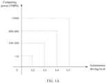
- L2 autonomous driving requires >10 TOPS (where one trillion operations are performed per second) computing power
- L3 autonomous driving requires 100 TOPS to 200 TOPS computing power
- L4 autonomous driving requires 400 TOPS to 600 TOPS computing power
- L5 autonomous driving requires >3000 TOPS computing power.
- power consumption of the vehicle-mounted intelligent computing platform and a chip thereof is continuously increased.
- power consumption of the vehicle-mounted intelligent computing platform that implements the L5 autonomous driving exceeds 370 W
- power consumption of a master chip exceeds 200 W.
- FIG. 2A shows an electronic device for implementing a heat dissipation solution for an electronic component.
- the electronic device includes a housing assembly 10, a circuit board 20, and an electronic component 30.
- the housing assembly 10 includes an upper housing 101 and a bottom housing 102 that are assembled together.
- Installation space for installing the circuit board 20 and the electronic component 30 is formed by encircling the upper housing 101 and the bottom housing 102, and a plurality of protruding parts 101P that protrude towards the bottom housing 102 and that are located in the installation space are further formed on the upper housing 101.
- the circuit board (for example, a printed circuit board) 20 is fastened to the upper housing 101 through the plurality of protruding parts 101P, and the electronic component (for example, a chip) 30 is fastened to and installed on the circuit board 20 and is located between the circuit board 20 and the upper housing 101.
- the electronic device further includes a thermally conductive material layer (for example, a gel layer) that is disposed between the electronic component 30 and the upper housing 101 and that is configured to conduct heat.
- the thermally conductive material layer is configured to absorb a dimension chain tolerance of two installation structures, in a height direction T, in which the circuit board 20 is installed in the upper housing 101 and the electronic component 30 is installed on the circuit board 20.
- the electronic component 30 can transfer heat to the upper housing 101 through the thermally conductive material layer, so that the electronic component 30 can dissipate heat through the upper housing 101.
- a tolerance range of the dimension chain tolerance is usually ⁇ 0.35 mm, and a thickness of the thermally conductive material layer is not less than 0.2 mm, a maximum thickness of the thermally conductive material layer reaches about 0.9 mm. Therefore, the thermally conductive material layer has a large thickness and a high thermal resistance, and therefore is not suitable for heat dissipation of the electronic component 30 with high power consumption and high heat density.
- FIG. 2B shows an electronic device for implementing another heat dissipation solution for the electronic component.
- the electronic device further includes a temperature equalization plate 40 (for example, a vacuum temperature equalization plate).
- the temperature equalization plate 40 is disposed between the electronic component 30 and the upper housing 101, and silicone grease is filled between the temperature equalization plate 40 and the electronic component 30 to improve a heat conduction capability.
- the thermally conductive material layer (for example, a gel layer) is disposed between the temperature equalization plate 40 and the upper housing 101. In this way, compared with that in the heat dissipation solution shown in FIG.
- a contact area between the temperature equalization plate 40 and the upper housing 101 is larger (greater than a contact area between the electronic component 30 and the upper housing 101 in FIG. 2A ), and both the thermally conductive material layer and the temperature equalization plate 40 have high thermal conductivity. Therefore, compared with the heat dissipation solution shown in FIG. 2A , this solution improves a heat dissipation capability of the electronic component 30.
- the temperature equalization plate 40 is added to an electronic chip, adversely affecting the dimension chain tolerance. Therefore, when the thermally conductive material layer is used in the electronic device to compensate for the dimension chain tolerance, the thickness of the thermally conductive material layer may be further increased, and may reach 1.2 mm at most.
- FIG. 2C shows an electronic device for implementing still another heat dissipation solution for the electronic component.
- a difference between the electronic device and the electronic device in FIG. 2A lies in that a floating heat sink 50 is installed on the upper housing 101 in the electronic device.
- the floating heat sink 50 is in contact with the electronic component 30 through an opening of the upper housing 101, and silicone grease is filled between the electronic component 30 and the floating heat sink 50.
- a floating feature of the floating heat sink 50 is used to absorb the dimension chain tolerance in the height direction T, and the floating heat sink 50 can effectively dissipate heat for the electronic component 30.
- this heat dissipation solution a heat transfer path between the electronic component 30 and the upper housing 101 is shorter, and heat dissipation effect is better, so that this heat dissipation solution can be better applied to heat dissipation of the electronic component 30 that has high power consumption and high heat density and that has a high heat dissipation requirement.
- the floating heat sink 50 is disposed outside the housing assembly 10, and the opening needs to be provided on the upper housing 101 to enable the floating heat sink 50 to be in contact with the electronic component 30. Therefore, this heat dissipation solution cannot meet a requirement of a standard such as IP67 and has a high risk in shielding and anti-corrosion of the electronic component 30, and costs are high.
- an electronic device having a floating support structure can implement a floating support solution for an electronic component, so that the electronic component abuts against a housing assembly, to better implement heat dissipation of the electronic component with high power consumption and high heat density through the housing assembly.
- the electronic device can easily meet a requirement of a related standard such as dustproof and anti-corrosion.
- an embodiment of this application provides an electronic device having a floating support structure.
- the electronic device includes: a housing assembly, where installation space is formed in the housing assembly; a circuit board, where the circuit board is accommodated in the installation space and installed in the housing assembly; an electronic component, where the electronic component is accommodated in the installation space and supported by the circuit board, and the electronic component is in signal communication with the circuit board; and a floating support assembly, where the floating support assembly is accommodated in the installation space, and the floating support assembly is disposed on the circuit board to support the electronic component or disposed in the housing assembly to support the circuit board, so that the electronic component abuts against the housing assembly under an action of a pre-loading force of the floating support assembly.
- the floating support assembly can abut the electronic component against the housing assembly, to implement heat dissipation of the electronic component through the housing assembly.
- the floating support assembly can replace a thermally conductive material layer to compensate for a dimension chain tolerance of the electronic device, to avoid affecting heat dissipation of the electronic component due to an excessive thickness of the thermally conductive material layer.
- the circuit board is fastened to and installed on the housing assembly.
- the floating support assembly includes: a daughter board, where the electronic component is fastened to and installed on the daughter board, and the daughter board is located between the circuit board and the electronic component; and an elastic support piece, where the elastic support piece is disposed between the daughter board and the circuit board, to apply the pre-loading force to the daughter board from an opposite side of a side that is of the daughter board and on which the electronic component is installed.
- the daughter board expands a layout range of a chip and improves layout flexibility of the chip.
- the elastic support piece is disposed, so that magnitude of the pre-loading force can be flexibly adjusted.
- the floating support assembly further includes a connecting piece, where the connecting piece passes through the daughter board and extends to the circuit board, to enable the daughter board to be connected to the circuit board; and in a state in which the daughter board is connected to the circuit board through the connecting piece, the daughter board and the circuit board can move relative to each other within a predetermined range.
- the daughter board can appropriately adjust a location relative to the circuit board when the pre-loading force is applied, to ensure that the electronic component always abuts against the housing assembly.
- the elastic support piece is a coil spring, and the coil spring is sleeved on the connecting piece.
- the elastic floating is implemented in a simpler structure, and installation and fastening between the elastic support piece and the connecting piece are easily implemented.
- the daughter board has a daughter board connection end; and the circuit board has a circuit board connection end corresponding to the daughter board connection end.
- the daughter board connection end and the circuit board connection end are inserted to each other, so that the signal communication between the electronic component and the circuit board is implemented through the daughter board, the daughter board connection end, and the circuit board connection end.
- the daughter board connection end and the circuit board connection end can move relative to each other with a relative movement between the daughter board and the circuit board.
- the electronic component is fastened to and installed on the circuit board.
- the floating support assembly includes a plurality of elastic support pieces, the plurality of elastic support pieces are disposed between an end face of the circuit board and the housing assembly, and the plurality of elastic support pieces are configured to apply the pre-loading force to the end face of the circuit board.
- the floating support assembly is implemented in a simpler structure and a more flexible manner.
- a plurality of protruding parts facing the installation space are formed on the housing assembly, and the plurality of protruding parts extend towards the circuit board and pass through the circuit board.
- Each elastic support piece is sleeved on a part that is of the protruding part and that is located on one side of the circuit board, so that the elastic support piece generates the pre-loading force to abut the electronic device disposed on the other side of the circuit board against the housing assembly.
- the floating support assembly is implemented in a simpler structure.
- each protruding part includes a main body part and a flange part, the main body part extends through the circuit board from one side of the circuit board, and the flange part is disposed on a part that is of the main body part and that is located on the other side of the circuit board.
- the elastic support piece is a coil spring, one end of the coil spring abuts against the circuit board, and the other end abuts against the flange part.
- the floating support assembly is implemented in a simpler structure.
- the electronic component is fastened to and installed on the circuit board.
- the floating support assembly includes a plurality of elastic support pieces, the plurality of elastic support pieces are disposed between an outer peripheral part of the circuit board and the housing assembly, and the plurality of elastic support pieces are configured to apply the pre-loading force to the outer peripheral part of the circuit board.
- the floating support assembly is implemented in a simpler structure and a more flexible manner.
- the elastic support pieces are elastic sheets.
- the elastic sheets are arranged at intervals around the outer peripheral part of the circuit board, one end of each elastic sheet is connected to the outer peripheral part, and the other end is connected to the housing assembly.
- the floating support assembly is implemented in a simpler structure.
- the housing assembly includes an upper housing and a bottom housing, and the upper housing is fastened to the bottom housing in a detachable manner.
- the electronic component abuts against the upper housing.
- the upper housing has a top and a side wall part that extends from the top to the bottom housing, and the electronic component abuts against the top.
- heat dissipation effect of the electronic component through the housing assembly is better, and a force-bearing condition of the electronic component is better.
- the electronic device further includes a thermally conductive material layer, where the thermally conductive material layer is disposed between the upper housing and the electronic component.
- heat dissipation effect of the electronic component through the housing assembly is better.
- the circuit board is a board or a coupling board
- the electronic component is a chip
- example herein means “used as an example, embodiment or illustration”. Any embodiment described as an “example” is not necessarily explained as being superior to or better than other embodiments.
- the "height direction” is a height direction of a housing assembly, and is also consistent with a thickness direction of each of a circuit board and a chip in example embodiments of specific implementations.
- the electronic device having the floating support structure includes a housing assembly 1, a circuit board 2, an electronic component 3, and a floating support assembly 4 that are assembled together.
- Installation space is formed in the housing assembly 1, and the circuit board 2, the electronic component 3, and the floating support assembly 4 are all accommodated in the installation space of the housing assembly 1.
- the floating support assembly 4 is disposed on the circuit board 2 to be supported by the circuit board 2, and the electronic component 3 is disposed on the floating support assembly 4 to be supported by the floating support assembly 4. Therefore, the floating support assembly 4 is located between the circuit board 2 and the electronic component 3.
- the housing assembly 1 includes an upper housing 11 and a bottom housing 12 that are assembled together.
- the upper housing 11 is fastened to the bottom housing 12 in a detachable manner.
- the upper housing 11 has a plate-shaped top 111 and a side wall part 112 that extends from a peripheral part of the top 111 towards the bottom housing 12.
- the bottom housing 12 has a plate-shaped structure, to seal an opening formed by the side wall part 112 of the upper housing 11. Therefore, the installation space of the housing assembly 1 is formed by encircling the top 111, the side wall part 112, and the bottom housing 12 of the upper housing 11.
- first protruding parts 11P protruding towards the bottom housing 12 are formed on the top 111 of the upper housing 11.
- the first protruding parts 11P do not extend to the bottom housing 12, but sufficient space is reserved between free ends of the first protruding parts 11P and the bottom housing 12. In this way, the circuit board 2 can be installed at the free ends of the first protruding parts 11P, so that the circuit board 2 is fastened to the upper housing 11.
- the entire circuit board 2 has a rectangular flat-plate shape and is a printed circuit board in a board form.
- the circuit board 2 is accommodated in the installation space and is fastened to the first protruding parts 11P of the upper housing 11 in a manner in which the circuit board 2 is approximately parallel to the top 111 of the upper housing 11, and sufficient space is reserved between the circuit board 2 and the top 111 of the upper housing 11 for disposing the electronic component 3 and the floating support assembly 4.
- circuit board 2 is further provided with a circuit board connection end 2c that is configured to connect to a daughter board connection end 41c of a daughter board 41 of the floating support assembly 4 in a matched manner.
- the circuit board connection end 2c protrudes from the circuit board 2 towards an upper part in FIG. 3A and forms a socket part for inserting the daughter board connection end 41c.
- the electronic component 3 is a chip and is fastened to and installed on the daughter board 41 of the floating support assembly 4. Under an action of an elastic support piece 43 of the floating support assembly 4, the electronic component 3 abuts against the top 111 of the upper housing 11 from a lower part in FIG. 3A , so that the electronic component 3 can dissipate heat through the top 111 of the upper housing 11.
- the floating support assembly 4 in a height direction T (namely, an up-down direction in FIG. 3A ), the floating support assembly 4 is disposed between the electronic component 3 and the circuit board 2, and the electronic component 3 abuts against the top 111 of the upper housing 11 under support of a pre-loading force of the floating support assembly 4.
- the floating support assembly 4 includes the daughter board 41, a connecting piece 42, and the elastic support piece 43 that are assembled together.
- the entire daughter board 41 has a rectangular flat-plate shape and is located below the electronic component 3, and the electronic component 3 is fastened to and installed on a pre-designed location of the daughter board 41 for installing the electronic component 3.
- An area of the daughter board 41 is less than an area of the circuit board 2, and therefore the daughter board 41 and the circuit board 2 completely overlap in the height direction T.
- the daughter board 41 has the daughter board connection end 41c that matches the circuit board connection end 2c of the circuit board 2.
- the daughter board connection end 41c can be inserted into the socket part of the circuit board connection end 2c, to implement signal communication between the daughter board connection end 41c and the circuit board connection end 2c.
- signal communication between the circuit board 2 and the electronic component 3 can be implemented through the daughter board 41, the daughter board connection end 41c, and the circuit board connection end 2c, and the signal communication implemented through the daughter board connection end 41c and the circuit board connection end 2c has features such as a large through-current capacity and a multi-signal transmission capability.
- the connecting piece 42 is, for example, a bolt or a pin.
- the connecting piece 42 passes through a through hole formed by four corners of the daughter board 41, to extend to the circuit board 2 and connect to a corresponding part of the circuit board 2.
- the daughter board 41 and the circuit board 2 can move relative to each other within a predetermined range in a direction (namely, the up-down direction in FIG. 3A ) in which the pre-loading force is applied.
- the daughter board connection end 41c and the circuit board connection end 2c can move relative to each other with a relative movement of the daughter board 41 and the circuit board 2. In this way, even if the daughter board connection end 41c and the circuit board connection end 2c move relative to each other, a connection relationship between the daughter board connection end 41c and the circuit board connection end 2c is not affected, so that signal quality and connection reliability are ensured.
- the elastic support piece 43 may be, for example, a cylindrical coil spring and sleeved on a part that is of the connecting piece 42 and that is located between the daughter board 41 and the circuit board 2. One axial end of the cylindrical coil spring abuts against the daughter board 41, and the other end abuts against the circuit board 2. In this way, the elastic support piece 43 applies the pre-loading force to the daughter board 41 from a side (namely, a lower side in FIG. 3A ) opposite to the side (namely, an upper side in FIG. 3A ) that is of the daughter board 41 and on which the electronic component 3 is installed, to further apply the pre-loading force to the electronic component 3.
- a side namely, a lower side in FIG. 3A
- the side namely, an upper side in FIG. 3A
- the floating support assembly 4 is disposed between the circuit board 2 and the electronic component 3.
- the electronic component 3 can abut against the top 111 of the upper housing 11 under an action of the pre-loading force of the floating support assembly 4, to ensure that heat generated by the electronic component 3 is transferred to the top 111 of the housing through a shortest heat transfer path when the electronic component 3 transfers the heat to the upper housing 11. Therefore, a thermal resistance is significantly reduced, and a heat dissipation capability of the electronic component 3 is effectively improved.
- a thermally conductive material layer between the electronic component 3 and the top 111 of the upper housing 11 is replaced, and the floating support assembly 4 can further support the daughter board 41 in a manner in which the daughter board 41 floats up and down relative to the circuit board 2 (in other words, relatively moves in the height direction T), to compensate for a dimension chain tolerance in the height direction T.
- the floating support assembly 4 is disposed on first protruding parts 11P of the upper housing 11, and the electronic component 3 is directly fastened to and installed on a corresponding part of the circuit board 2.
- the floating support assembly 4 includes a plurality of elastic support pieces 43 that are disposed on a lower end face of the circuit board 2 and that are sleeved on the first protruding parts 11P, and the elastic support pieces 43 may all be cylindrical coil springs.
- the electronic component 3 is located above the circuit board 2, and the plurality of elastic support pieces 43 are located below the circuit board 2. Therefore, the electronic component 3 and the plurality of elastic support pieces 43 are located on an opposite side of the circuit board 2.
- One end of each elastic support piece 43 abuts against the circuit board 2, and the other end abuts against the first protruding part 11P, so that each elastic support piece 43 is configured to apply a pre-loading force facing upward to the circuit board 2.
- the plurality of first protruding parts 11P of the upper housing 11 that protrude towards the circuit board 2 pass through the circuit board 2, and each elastic support piece 43 is sleeved on a part that is of the first protruding part 11P and that is located below the circuit board 2, so that the electronic component 3 disposed above the circuit board 2 abuts against the top 111 of the upper housing 11 under an action of the pre-loading force generated by the elastic support piece 43.
- each first protruding part 11P includes a main body part 11P1 that is fastened to each other and that has a cylindrical shape and a flange part 11P2 that is located in the main body part 11P1 and that is away from a free end of the upper housing 11.
- the main body part 11P 1 extends through the circuit board 2 from the upper part of the circuit board 2, the flange part 11P2 is disposed on a part that is of the main body part 11P1 and that is located below the circuit board 2, and an outer diameter of the flange part 11P2 is greater than an outer diameter of the main body part 11P1.
- the flange part 11P2 may be connected to the main body part 11P1 through various means.
- the flange part 11P2 may be connected to the main body part 11P1 through a screw.
- the entire first protruding part 11P may be located above the circuit board 2, and the circuit board 2 may be connected to the first protruding part 11P through a support piece or a connecting piece such as a screw.
- the support piece or the connecting piece such as a screw is connected to the first protruding part 11P through a corresponding hole in the circuit board 2.
- One end of an elastic piece such as a coil spring abuts against the circuit board 2, and the other end abuts against a lower end (namely, a flange) of the support piece or the connecting piece such as a screw.
- the floating support assembly 4 is disposed on second protruding parts 12P of the bottom housing 12, and the electronic component 3 is directly fastened to and installed on a corresponding part of the circuit board 2.
- the floating support assembly 4 includes a plurality of elastic support pieces 43 disposed between a lower end face of the circuit board 2 and the second protruding parts 12P, and the elastic support pieces 43 may all be cylindrical coil springs.
- the electronic component 3 is located above the circuit board 2, and the plurality of elastic support pieces 43 are located below the circuit board 2. Therefore, the electronic component 3 and the plurality of elastic support pieces 43 are located on an opposite side of the circuit board 2.
- One end of each elastic support piece 43 abuts against the circuit board 2, and the other end abuts against the second protruding part 12P, so that each elastic support piece 43 is configured to apply a pre-loading force to the circuit board 2.
- circuit board 2 may be connected to the second protruding part 12P through a support piece or a connecting piece such as a screw, the circuit board 2 may move relative to the support piece or the connecting piece in the height direction T, and the elastic support piece 43 may be sleeved on the support piece or the connecting piece.
- the first protruding parts 11P of the upper housing 11 are omitted.
- the plurality of second protruding parts 12P protruding towards the circuit board 2 are formed on the upper housing 11, and each elastic support piece 43 is disposed on the second protruding part 12P, so that the elastic support piece 43 applies the pre-loading force to the circuit board 2.
- the floating support assembly 4 is disposed on first protruding parts 11P of the upper housing 11, and the electronic component 3 is directly installed on a corresponding part of the circuit board 2.
- the floating support assembly 4 includes a plurality of elastic support pieces 43' disposed between an outer peripheral part of the circuit board 2 and the first protruding parts 11P of the upper housing 11, and the plurality of elastic support pieces 43' are configured to apply pre-loading forces to the circuit board 2.
- the elastic support pieces 43' may be elastic sheets.
- the plurality of elastic sheets are arranged at intervals around the outer peripheral part of the circuit board 2, one end of each elastic sheet is connected to the outer peripheral part of the circuit board 2, and the other end is connected to the first protruding part 11P of the upper housing 11. In this way, the pre-loading force is applied to the circuit board 2 by using a structure of the elastic sheet.
- floating support assemblies 4 having different structures are described in the foregoing embodiments, it may be understood that the floating support assemblies 4 described in the second example embodiment to the fourth example embodiment can implement same effect as the floating support assembly 4 in the first example embodiment.
- the foregoing describes example embodiments of specific implementations of this application and a related variation example. The following provides supplementary description.
- the solutions in this application have a simple structure and low costs, and support various types of heat dissipation solutions such as air cooling and liquid cooling.
Landscapes
- Engineering & Computer Science (AREA)
- Microelectronics & Electronic Packaging (AREA)
- Physics & Mathematics (AREA)
- Thermal Sciences (AREA)
- Mechanical Engineering (AREA)
- Cooling Or The Like Of Electrical Apparatus (AREA)
Abstract
Description
- This application claims priority to
Chinese Patent Application No. 202011355048.6, filed with the China National Intellectual Property Administration on November 27, 2020 - This application relates to a support heat dissipation structure of an electronic component in an electronic device, and in particular, to an electronic device having a floating support structure.
- Computing power of an electronic component in an existing electronic device is increasingly powerful. Therefore, power consumption of the electronic component is increased, and a heat generating capacity is also increased. For example, as shown in
FIG. 1A to FIG. 1D , in an intelligent vehicle, as an autonomous driving level continuously increases, power consumption and a heat generating capacity of a chip (an example of the electronic component) configured to implement autonomous driving are continuously increased. As a core of autonomous driving, a vehicle-mounted intelligent computing platform needs to connect to a plurality of types of sensors. Each sensor (such as a camera or a laser radar) generates data of 20 M Byte to 100 M Byte per second. A large amount of data generated by the plurality of sensors needs to be analyzed and processed in real time within dozens of milliseconds. Therefore, a requirement on chip performance of the vehicle-mounted intelligent computing platform is very high. Generally, L2 autonomous driving requires >10 TOPS (where one trillion operations are performed per second) computing power, L3 autonomous driving requires 100 TOPS to 200 TOPS computing power, L4 autonomous driving requires 400 TOPS to 600 TOPS computing power, and L5 autonomous driving requires >3000 TOPS computing power. As a requirement on the computing power continuously increases, power consumption of the vehicle-mounted intelligent computing platform and a chip thereof is continuously increased. In the future, power consumption of the vehicle-mounted intelligent computing platform that implements the L5 autonomous driving exceeds 370 W, and power consumption of a master chip exceeds 200 W. Therefore, to ensure a stable and normal operation of electronic components such as the master chip of the vehicle-mounted intelligent computing platform, effective heat dissipation of the electronic components needs to be ensured. Therefore, a technical person uses different heat dissipation solutions for such an electronic component. -
FIG. 2A shows an electronic device for implementing a heat dissipation solution for an electronic component. As shown inFIG. 2A , the electronic device includes ahousing assembly 10, acircuit board 20, and anelectronic component 30. Thehousing assembly 10 includes anupper housing 101 and abottom housing 102 that are assembled together. Installation space for installing thecircuit board 20 and theelectronic component 30 is formed by encircling theupper housing 101 and thebottom housing 102, and a plurality of protrudingparts 101P that protrude towards thebottom housing 102 and that are located in the installation space are further formed on theupper housing 101. The circuit board (for example, a printed circuit board) 20 is fastened to theupper housing 101 through the plurality of protrudingparts 101P, and the electronic component (for example, a chip) 30 is fastened to and installed on thecircuit board 20 and is located between thecircuit board 20 and theupper housing 101. In addition, the electronic device further includes a thermally conductive material layer (for example, a gel layer) that is disposed between theelectronic component 30 and theupper housing 101 and that is configured to conduct heat. In an aspect, the thermally conductive material layer is configured to absorb a dimension chain tolerance of two installation structures, in a height direction T, in which thecircuit board 20 is installed in theupper housing 101 and theelectronic component 30 is installed on thecircuit board 20. In another aspect, theelectronic component 30 can transfer heat to theupper housing 101 through the thermally conductive material layer, so that theelectronic component 30 can dissipate heat through theupper housing 101. In the electronic device, because a tolerance range of the dimension chain tolerance is usually ±0.35 mm, and a thickness of the thermally conductive material layer is not less than 0.2 mm, a maximum thickness of the thermally conductive material layer reaches about 0.9 mm. Therefore, the thermally conductive material layer has a large thickness and a high thermal resistance, and therefore is not suitable for heat dissipation of theelectronic component 30 with high power consumption and high heat density. -
FIG. 2B shows an electronic device for implementing another heat dissipation solution for the electronic component. As shown inFIG. 2B , a difference between the electronic device and the electronic device inFIG. 2A lies in that the electronic device further includes a temperature equalization plate 40 (for example, a vacuum temperature equalization plate). Thetemperature equalization plate 40 is disposed between theelectronic component 30 and theupper housing 101, and silicone grease is filled between thetemperature equalization plate 40 and theelectronic component 30 to improve a heat conduction capability. The thermally conductive material layer (for example, a gel layer) is disposed between thetemperature equalization plate 40 and theupper housing 101. In this way, compared with that in the heat dissipation solution shown inFIG. 2A , a contact area between thetemperature equalization plate 40 and theupper housing 101 is larger (greater than a contact area between theelectronic component 30 and theupper housing 101 inFIG. 2A ), and both the thermally conductive material layer and thetemperature equalization plate 40 have high thermal conductivity. Therefore, compared with the heat dissipation solution shown inFIG. 2A , this solution improves a heat dissipation capability of theelectronic component 30. However, thetemperature equalization plate 40 is added to an electronic chip, adversely affecting the dimension chain tolerance. Therefore, when the thermally conductive material layer is used in the electronic device to compensate for the dimension chain tolerance, the thickness of the thermally conductive material layer may be further increased, and may reach 1.2 mm at most. In addition, a heat transfer path between theelectronic component 30 and theupper housing 101 becomes longer, resulting in a larger thermal resistance between theelectronic component 30 and theupper housing 101. Therefore, compared with the heat dissipation solution shown inFIG. 2A , this solution has limited improvement on heat dissipation effect of theelectronic component 30 with high power consumption and high heat density. -
FIG. 2C shows an electronic device for implementing still another heat dissipation solution for the electronic component. As shown inFIG. 2C , a difference between the electronic device and the electronic device inFIG. 2A lies in that afloating heat sink 50 is installed on theupper housing 101 in the electronic device. The floatingheat sink 50 is in contact with theelectronic component 30 through an opening of theupper housing 101, and silicone grease is filled between theelectronic component 30 and the floatingheat sink 50. In this way, a floating feature of the floatingheat sink 50 is used to absorb the dimension chain tolerance in the height direction T, and thefloating heat sink 50 can effectively dissipate heat for theelectronic component 30. Therefore, in this heat dissipation solution, a heat transfer path between theelectronic component 30 and theupper housing 101 is shorter, and heat dissipation effect is better, so that this heat dissipation solution can be better applied to heat dissipation of theelectronic component 30 that has high power consumption and high heat density and that has a high heat dissipation requirement. However, in this heat dissipation solution, the floatingheat sink 50 is disposed outside thehousing assembly 10, and the opening needs to be provided on theupper housing 101 to enable the floatingheat sink 50 to be in contact with theelectronic component 30. Therefore, this heat dissipation solution cannot meet a requirement of a standard such as IP67 and has a high risk in shielding and anti-corrosion of theelectronic component 30, and costs are high. - In view of this, an electronic device having a floating support structure is provided. The electronic device can implement a floating support solution for an electronic component, so that the electronic component abuts against a housing assembly, to better implement heat dissipation of the electronic component with high power consumption and high heat density through the housing assembly. In addition, the electronic device can easily meet a requirement of a related standard such as dustproof and anti-corrosion.
- According to a first aspect, an embodiment of this application provides an electronic device having a floating support structure. The electronic device includes: a housing assembly, where installation space is formed in the housing assembly; a circuit board, where the circuit board is accommodated in the installation space and installed in the housing assembly; an electronic component, where the electronic component is accommodated in the installation space and supported by the circuit board, and the electronic component is in signal communication with the circuit board; and a floating support assembly, where the floating support assembly is accommodated in the installation space, and the floating support assembly is disposed on the circuit board to support the electronic component or disposed in the housing assembly to support the circuit board, so that the electronic component abuts against the housing assembly under an action of a pre-loading force of the floating support assembly.
- According to the technical solution, the floating support assembly can abut the electronic component against the housing assembly, to implement heat dissipation of the electronic component through the housing assembly. In addition, the floating support assembly can replace a thermally conductive material layer to compensate for a dimension chain tolerance of the electronic device, to avoid affecting heat dissipation of the electronic component due to an excessive thickness of the thermally conductive material layer.
- According to the first aspect, in a first possible implementation of the electronic device, the circuit board is fastened to and installed on the housing assembly. The floating support assembly includes: a daughter board, where the electronic component is fastened to and installed on the daughter board, and the daughter board is located between the circuit board and the electronic component; and an elastic support piece, where the elastic support piece is disposed between the daughter board and the circuit board, to apply the pre-loading force to the daughter board from an opposite side of a side that is of the daughter board and on which the electronic component is installed.
- According to the technical solution, the daughter board expands a layout range of a chip and improves layout flexibility of the chip. In addition, the elastic support piece is disposed, so that magnitude of the pre-loading force can be flexibly adjusted.
- According to the first possible implementation of the first aspect, the floating support assembly further includes a connecting piece, where the connecting piece passes through the daughter board and extends to the circuit board, to enable the daughter board to be connected to the circuit board; and in a state in which the daughter board is connected to the circuit board through the connecting piece, the daughter board and the circuit board can move relative to each other within a predetermined range.
- According to the technical solution, the daughter board can appropriately adjust a location relative to the circuit board when the pre-loading force is applied, to ensure that the electronic component always abuts against the housing assembly.
- According to the first possible implementation of the first aspect or based on any implementation of the first possible implementation, the elastic support piece is a coil spring, and the coil spring is sleeved on the connecting piece. According to the technical solution, the elastic floating is implemented in a simpler structure, and installation and fastening between the elastic support piece and the connecting piece are easily implemented.
- According to the first possible implementation of the first aspect, or based on any implementation the first possible implementation, the daughter board has a daughter board connection end; and the circuit board has a circuit board connection end corresponding to the daughter board connection end. The daughter board connection end and the circuit board connection end are inserted to each other, so that the signal communication between the electronic component and the circuit board is implemented through the daughter board, the daughter board connection end, and the circuit board connection end.
- According to the technical solution, effective signal communication between the electronic component and the circuit board can be ensured.
- According to the first possible implementation of the first aspect, or based on any implementation the first possible implementation, the daughter board connection end and the circuit board connection end can move relative to each other with a relative movement between the daughter board and the circuit board.
- According to the technical solution, even if the daughter board and the circuit board move relative to each other under floating support of the floating support assembly, the effective signal communication between the electronic component and the circuit board can be ensured.
- According to the first aspect, in a second possible implementation of the electronic device, the electronic component is fastened to and installed on the circuit board. The floating support assembly includes a plurality of elastic support pieces, the plurality of elastic support pieces are disposed between an end face of the circuit board and the housing assembly, and the plurality of elastic support pieces are configured to apply the pre-loading force to the end face of the circuit board.
- According to the technical solution, the floating support assembly is implemented in a simpler structure and a more flexible manner.
- According to the second possible implementation of the first aspect, a plurality of protruding parts facing the installation space are formed on the housing assembly, and the plurality of protruding parts extend towards the circuit board and pass through the circuit board. Each elastic support piece is sleeved on a part that is of the protruding part and that is located on one side of the circuit board, so that the elastic support piece generates the pre-loading force to abut the electronic device disposed on the other side of the circuit board against the housing assembly.
- According to the technical solution, the floating support assembly is implemented in a simpler structure.
- According to the second possible implementation of the first aspect, or based on any implementation of the second possible implementation, each protruding part includes a main body part and a flange part, the main body part extends through the circuit board from one side of the circuit board, and the flange part is disposed on a part that is of the main body part and that is located on the other side of the circuit board. The elastic support piece is a coil spring, one end of the coil spring abuts against the circuit board, and the other end abuts against the flange part.
- According to the technical solution, the floating support assembly is implemented in a simpler structure.
- According to the first aspect, in a third possible implementation of the electronic device, the electronic component is fastened to and installed on the circuit board. The floating support assembly includes a plurality of elastic support pieces, the plurality of elastic support pieces are disposed between an outer peripheral part of the circuit board and the housing assembly, and the plurality of elastic support pieces are configured to apply the pre-loading force to the outer peripheral part of the circuit board.
- According to the technical solution, the floating support assembly is implemented in a simpler structure and a more flexible manner.
- According to the third possible implementation of the first aspect, the elastic support pieces are elastic sheets. The elastic sheets are arranged at intervals around the outer peripheral part of the circuit board, one end of each elastic sheet is connected to the outer peripheral part, and the other end is connected to the housing assembly.
- According to the technical solution, the floating support assembly is implemented in a simpler structure.
- According to any one of the first aspect or the possible implementations of the first aspect, the housing assembly includes an upper housing and a bottom housing, and the upper housing is fastened to the bottom housing in a detachable manner. The electronic component abuts against the upper housing.
- According to the technical solution, layouts of the electronic component and the circuit board can be more flexible. According to any one of the first aspect or the possible implementations of the first aspect, the upper housing has a top and a side wall part that extends from the top to the bottom housing, and the electronic component abuts against the top.
- According to the technical solution, heat dissipation effect of the electronic component through the housing assembly is better, and a force-bearing condition of the electronic component is better.
- According to any one of the first aspect or the possible implementations of the first aspect, the electronic device further includes a thermally conductive material layer, where the thermally conductive material layer is disposed between the upper housing and the electronic component.
- According to the technical solution, heat dissipation effect of the electronic component through the housing assembly is better.
- According to any one of the first aspect or the possible implementations of the first aspect, the circuit board is a board or a coupling board, and the electronic component is a chip.
- According to the technical solution, an application scope of the solutions in this application is wider.
- These aspects and other aspects of this application are more concise and more comprehensive in descriptions of the following (a plurality of) embodiments.
- The accompanying drawings included in this specification and constituting a part of this specification and this specification jointly show example embodiments, features, and aspects of this application, and are intended to explain the principles of this application.
-
FIG. 1A is a curve diagram depicting a requirement trend of computing power required for implementing different levels of autonomous driving of an intelligent vehicle; -
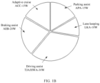
FIG. 1B is a schematic diagram depicting functions and power consumption of an L2/ADAS (advanced driver assistance system); -
FIG. 1C is a distribution diagram of functions of an autonomous driving domain controller of an intelligent vehicle; -
FIG. 1D is a table depicting computing power and power consumption that are required for implementing different levels of autonomous driving of an intelligent vehicle; -
FIG. 2A is a schematic sectional view of an electronic device for implementing a heat dissipation solution for an electronic component;FIG. 2B is a schematic sectional view of an electronic device for implementing another heat dissipation solution for an electronic component; andFIG. 2C is a schematic sectional view of an electronic device for implementing still another heat dissipation solution for an electronic component; -
FIG. 3A is a schematic sectional view of an electronic device having a floating support structure according to a first example embodiment of this application; andFIG. 3B is a schematic diagram of an exploded structure of the electronic device inFIG. 3A ; -
FIG. 4 is a schematic sectional view of an electronic device having a floating support structure according to a second example embodiment of this application; -
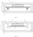
FIG. 5 is a schematic sectional view of an electronic device having a floating support structure according to a third example embodiment of this application; -
FIG. 6 is a schematic sectional view of an electronic device having a floating support structure according to a fourth example embodiment of this application; and -
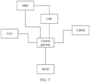
FIG. 7 is a schematic diagram of a connection structure of domain controllers of an intelligent vehicle, where the technical solutions in this application may be applied to support and heat dissipation of chips of the domain controllers. -
- 10: housing assembly; 101: upper housing; 101P: protruding part; 102: bottom housing; 20: circuit board; 30: electronic component; 40: temperature equalization plate; 50: floating heat sink;
- 1: housing assembly; 11: upper housing; 111: top; 112: side wall part; 11P: first protruding part; 11P1: main body part; 11P2: flange part; 12: bottom housing; 12P: second protruding part; 2: circuit board; 2c: circuit board connection end; 3: electronic component; 4: floating support assembly; 41: daughter board; 41c: daughter board connection end; 42: connecting piece; 43 or 43': elastic support piece; and
- T: height direction.
- The following describes various example embodiments, features, and aspects of this application in detail with reference to the accompanying drawings. Identical reference signs in the accompanying drawings indicate elements that have same or similar functions. Although various aspects of embodiments are illustrated in the accompanying drawing, the accompanying drawings are not necessarily drawn in proportion unless otherwise specified.
- The specific term "example" herein means "used as an example, embodiment or illustration". Any embodiment described as an "example" is not necessarily explained as being superior to or better than other embodiments.
- In addition, to better describe this application, many specific details are provided in the following specific embodiments. A person skilled in the art should understand that this application can also be implemented without some specific details. In some embodiments, methods, means, and elements that are well-known to a person skilled in the art are not described in detail, so that a main purpose of this application is highlighted.
- In this application, unless otherwise specified, the "height direction" is a height direction of a housing assembly, and is also consistent with a thickness direction of each of a circuit board and a chip in example embodiments of specific implementations.
- The following describes a specific structure of an electronic device having a floating support structure according to a first example embodiment of this application with reference to the accompanying drawings of this specification.
- As shown in
FIG. 3A andFIG. 3B , the electronic device having the floating support structure according to the first example embodiment of this application includes ahousing assembly 1, acircuit board 2, anelectronic component 3, and a floatingsupport assembly 4 that are assembled together. Installation space is formed in thehousing assembly 1, and thecircuit board 2, theelectronic component 3, and the floatingsupport assembly 4 are all accommodated in the installation space of thehousing assembly 1. The floatingsupport assembly 4 is disposed on thecircuit board 2 to be supported by thecircuit board 2, and theelectronic component 3 is disposed on the floatingsupport assembly 4 to be supported by the floatingsupport assembly 4. Therefore, the floatingsupport assembly 4 is located between thecircuit board 2 and theelectronic component 3. - Specifically, in this embodiment, the
housing assembly 1 includes anupper housing 11 and abottom housing 12 that are assembled together. Theupper housing 11 is fastened to thebottom housing 12 in a detachable manner. Theupper housing 11 has a plate-shapedtop 111 and aside wall part 112 that extends from a peripheral part of the top 111 towards thebottom housing 12. Thebottom housing 12 has a plate-shaped structure, to seal an opening formed by theside wall part 112 of theupper housing 11. Therefore, the installation space of thehousing assembly 1 is formed by encircling the top 111, theside wall part 112, and thebottom housing 12 of theupper housing 11. - It should be understood that, although descriptions such as the "upper housing" and the "bottom housing" are used in this application, a use status or posture of the electronic device in this application is not limited to the case shown in
FIG. 3A , and the electronic device in this application may be used in various statuses or postures. - In addition, a plurality of first protruding
parts 11P protruding towards thebottom housing 12 are formed on the top 111 of theupper housing 11. The first protrudingparts 11P do not extend to thebottom housing 12, but sufficient space is reserved between free ends of the first protrudingparts 11P and thebottom housing 12. In this way, thecircuit board 2 can be installed at the free ends of the first protrudingparts 11P, so that thecircuit board 2 is fastened to theupper housing 11. - In this embodiment, the
entire circuit board 2 has a rectangular flat-plate shape and is a printed circuit board in a board form. Thecircuit board 2 is accommodated in the installation space and is fastened to the first protrudingparts 11P of theupper housing 11 in a manner in which thecircuit board 2 is approximately parallel to the top 111 of theupper housing 11, and sufficient space is reserved between thecircuit board 2 and the top 111 of theupper housing 11 for disposing theelectronic component 3 and the floatingsupport assembly 4. - In addition, the
circuit board 2 is further provided with a circuitboard connection end 2c that is configured to connect to a daughterboard connection end 41c of adaughter board 41 of the floatingsupport assembly 4 in a matched manner. The circuit board connection end 2c protrudes from thecircuit board 2 towards an upper part inFIG. 3A and forms a socket part for inserting the daughterboard connection end 41c. - In this embodiment, the
electronic component 3 is a chip and is fastened to and installed on thedaughter board 41 of the floatingsupport assembly 4. Under an action of anelastic support piece 43 of the floatingsupport assembly 4, theelectronic component 3 abuts against the top 111 of theupper housing 11 from a lower part inFIG. 3A , so that theelectronic component 3 can dissipate heat through the top 111 of theupper housing 11. - In this embodiment, in a height direction T (namely, an up-down direction in
FIG. 3A ), the floatingsupport assembly 4 is disposed between theelectronic component 3 and thecircuit board 2, and theelectronic component 3 abuts against the top 111 of theupper housing 11 under support of a pre-loading force of the floatingsupport assembly 4. In this embodiment, the floatingsupport assembly 4 includes thedaughter board 41, a connectingpiece 42, and theelastic support piece 43 that are assembled together. - Specifically, the
entire daughter board 41 has a rectangular flat-plate shape and is located below theelectronic component 3, and theelectronic component 3 is fastened to and installed on a pre-designed location of thedaughter board 41 for installing theelectronic component 3. An area of thedaughter board 41 is less than an area of thecircuit board 2, and therefore thedaughter board 41 and thecircuit board 2 completely overlap in the height direction T. In addition, thedaughter board 41 has the daughterboard connection end 41c that matches the circuit board connection end 2c of thecircuit board 2. The daughterboard connection end 41c can be inserted into the socket part of the circuitboard connection end 2c, to implement signal communication between the daughterboard connection end 41c and the circuitboard connection end 2c. In this way, signal communication between thecircuit board 2 and theelectronic component 3 can be implemented through thedaughter board 41, the daughterboard connection end 41c, and the circuitboard connection end 2c, and the signal communication implemented through the daughterboard connection end 41c and the circuitboard connection end 2c has features such as a large through-current capacity and a multi-signal transmission capability. - The connecting
piece 42 is, for example, a bolt or a pin. The connectingpiece 42 passes through a through hole formed by four corners of thedaughter board 41, to extend to thecircuit board 2 and connect to a corresponding part of thecircuit board 2. In this way, in a state in which thedaughter board 41 is connected to thecircuit board 2 through the connectingpiece 42, thedaughter board 41 and thecircuit board 2 can move relative to each other within a predetermined range in a direction (namely, the up-down direction inFIG. 3A ) in which the pre-loading force is applied. Further, it may be understood that the daughterboard connection end 41c and the circuitboard connection end 2c can move relative to each other with a relative movement of thedaughter board 41 and thecircuit board 2. In this way, even if the daughterboard connection end 41c and the circuitboard connection end 2c move relative to each other, a connection relationship between the daughterboard connection end 41c and the circuitboard connection end 2c is not affected, so that signal quality and connection reliability are ensured. - The
elastic support piece 43 may be, for example, a cylindrical coil spring and sleeved on a part that is of the connectingpiece 42 and that is located between thedaughter board 41 and thecircuit board 2. One axial end of the cylindrical coil spring abuts against thedaughter board 41, and the other end abuts against thecircuit board 2. In this way, theelastic support piece 43 applies the pre-loading force to thedaughter board 41 from a side (namely, a lower side inFIG. 3A ) opposite to the side (namely, an upper side inFIG. 3A ) that is of thedaughter board 41 and on which theelectronic component 3 is installed, to further apply the pre-loading force to theelectronic component 3. - In the technical solution of the first embodiment, the floating
support assembly 4 is disposed between thecircuit board 2 and theelectronic component 3. In this way, theelectronic component 3 can abut against the top 111 of theupper housing 11 under an action of the pre-loading force of the floatingsupport assembly 4, to ensure that heat generated by theelectronic component 3 is transferred to the top 111 of the housing through a shortest heat transfer path when theelectronic component 3 transfers the heat to theupper housing 11. Therefore, a thermal resistance is significantly reduced, and a heat dissipation capability of theelectronic component 3 is effectively improved. In addition, a thermally conductive material layer between theelectronic component 3 and the top 111 of theupper housing 11 is replaced, and the floatingsupport assembly 4 can further support thedaughter board 41 in a manner in which thedaughter board 41 floats up and down relative to the circuit board 2 (in other words, relatively moves in the height direction T), to compensate for a dimension chain tolerance in the height direction T. - The following describes a specific structure of an electronic device having a floating support structure according to a second example embodiment of this application with reference to the accompanying drawings of this specification. (The structure of the electronic device having the floating support structure according to the second example embodiment of this application)
- For ease of description, in this embodiment, details about a part that is the same as the structure in the first example embodiment shown in
FIG. 3A andFIG. 3B are omitted. The following mainly describes a structure that is in this embodiment and that is different from that in the first embodiment. - In this embodiment, as shown in
FIG. 4 , the floatingsupport assembly 4 is disposed on first protrudingparts 11P of theupper housing 11, and theelectronic component 3 is directly fastened to and installed on a corresponding part of thecircuit board 2. - Further, the floating
support assembly 4 includes a plurality ofelastic support pieces 43 that are disposed on a lower end face of thecircuit board 2 and that are sleeved on the first protrudingparts 11P, and theelastic support pieces 43 may all be cylindrical coil springs. InFIG. 4 , theelectronic component 3 is located above thecircuit board 2, and the plurality ofelastic support pieces 43 are located below thecircuit board 2. Therefore, theelectronic component 3 and the plurality ofelastic support pieces 43 are located on an opposite side of thecircuit board 2. One end of eachelastic support piece 43 abuts against thecircuit board 2, and the other end abuts against the first protrudingpart 11P, so that eachelastic support piece 43 is configured to apply a pre-loading force facing upward to thecircuit board 2. - In cooperation with the structure in which the
elastic support pieces 43 are disposed, the plurality of first protrudingparts 11P of theupper housing 11 that protrude towards thecircuit board 2 pass through thecircuit board 2, and eachelastic support piece 43 is sleeved on a part that is of the first protrudingpart 11P and that is located below thecircuit board 2, so that theelectronic component 3 disposed above thecircuit board 2 abuts against the top 111 of theupper housing 11 under an action of the pre-loading force generated by theelastic support piece 43. More specifically, each first protrudingpart 11P includes a main body part 11P1 that is fastened to each other and that has a cylindrical shape and a flange part 11P2 that is located in the main body part 11P1 and that is away from a free end of theupper housing 11. Themain 1 extends through thebody part 11Pcircuit board 2 from the upper part of thecircuit board 2, the flange part 11P2 is disposed on a part that is of the main body part 11P1 and that is located below thecircuit board 2, and an outer diameter of the flange part 11P2 is greater than an outer diameter of the main body part 11P1. In this way, one end of theelastic support piece 43 sleeved on the main body part 11P1 abuts against thecircuit board 2, and the other end abuts against the flange part 11P2, so that theelastic support piece 43 can generate the expected pre-loading force. Herein, the flange part 11P2 may be connected to the main body part 11P1 through various means. For example, the flange part 11P2 may be connected to the main body part 11P1 through a screw. - In a variation example of the second example embodiment, the entire first protruding
part 11P may be located above thecircuit board 2, and thecircuit board 2 may be connected to the first protrudingpart 11P through a support piece or a connecting piece such as a screw. The support piece or the connecting piece such as a screw is connected to the first protrudingpart 11P through a corresponding hole in thecircuit board 2. One end of an elastic piece such as a coil spring abuts against thecircuit board 2, and the other end abuts against a lower end (namely, a flange) of the support piece or the connecting piece such as a screw. - The following describes a specific structure of an electronic device having a floating support structure according to a third example embodiment of this application with reference to the accompanying drawings of this specification. (The structure of the electronic device having the floating support structure according to the third example embodiment of this application)
- For ease of description, in this embodiment, details about a part that is the same as the structure in the second example embodiment shown in
FIG. 4 are omitted. The following mainly describes a structure that is in this embodiment and that is different from that in the second embodiment. - In this embodiment, as shown in
FIG. 5 , the floatingsupport assembly 4 is disposed on second protrudingparts 12P of thebottom housing 12, and theelectronic component 3 is directly fastened to and installed on a corresponding part of thecircuit board 2. - Further, the floating
support assembly 4 includes a plurality ofelastic support pieces 43 disposed between a lower end face of thecircuit board 2 and the second protrudingparts 12P, and theelastic support pieces 43 may all be cylindrical coil springs. Theelectronic component 3 is located above thecircuit board 2, and the plurality ofelastic support pieces 43 are located below thecircuit board 2. Therefore, theelectronic component 3 and the plurality ofelastic support pieces 43 are located on an opposite side of thecircuit board 2. One end of eachelastic support piece 43 abuts against thecircuit board 2, and the other end abuts against the second protrudingpart 12P, so that eachelastic support piece 43 is configured to apply a pre-loading force to thecircuit board 2. - It may be understood that the
circuit board 2 may be connected to the second protrudingpart 12P through a support piece or a connecting piece such as a screw, thecircuit board 2 may move relative to the support piece or the connecting piece in the height direction T, and theelastic support piece 43 may be sleeved on the support piece or the connecting piece. - In this embodiment, the first protruding
parts 11P of theupper housing 11 are omitted. Instead, the plurality of second protrudingparts 12P protruding towards thecircuit board 2 are formed on theupper housing 11, and eachelastic support piece 43 is disposed on the second protrudingpart 12P, so that theelastic support piece 43 applies the pre-loading force to thecircuit board 2. - The following describes a specific structure of an electronic device having a floating support structure according to a fourth example embodiment of this application with reference to the accompanying drawings of this specification. (The structure of the electronic device having the floating support structure according to the fourth example embodiment of this application)
- For ease of description, in this embodiment, details about a part that is the same as the structure in the second example embodiment shown in
FIG. 4 are omitted. The following mainly describes a structure that is in this embodiment and that is different from that in the second embodiment. - In this embodiment, as shown in
FIG. 6 , the floatingsupport assembly 4 is disposed on first protrudingparts 11P of theupper housing 11, and theelectronic component 3 is directly installed on a corresponding part of thecircuit board 2. The floatingsupport assembly 4 includes a plurality of elastic support pieces 43' disposed between an outer peripheral part of thecircuit board 2 and the first protrudingparts 11P of theupper housing 11, and the plurality of elastic support pieces 43' are configured to apply pre-loading forces to thecircuit board 2. In this embodiment, the elastic support pieces 43' may be elastic sheets. The plurality of elastic sheets are arranged at intervals around the outer peripheral part of thecircuit board 2, one end of each elastic sheet is connected to the outer peripheral part of thecircuit board 2, and the other end is connected to the first protrudingpart 11P of theupper housing 11. In this way, the pre-loading force is applied to thecircuit board 2 by using a structure of the elastic sheet. - Although the floating
support assemblies 4 having different structures are described in the foregoing embodiments, it may be understood that the floatingsupport assemblies 4 described in the second example embodiment to the fourth example embodiment can implement same effect as the floatingsupport assembly 4 in the first example embodiment. The foregoing describes example embodiments of specific implementations of this application and a related variation example. The following provides supplementary description. - i. Although not clearly described in the foregoing specific implementations, it may be understood that, to improve a capability of the
electronic component 3 to transfer heat to the top 111 of theupper housing 11, the electronic device may further include a thermally conductive material layer disposed between theupper housing 11 and theelectronic component 3. The thermally conductive material layer may be a highly conductive TIM (namely, a thermally conductive interface material) such as silicone grease or a phase change film. - ii. Although it is described in the foregoing specific implementations that the
circuit board 2 is a printed circuit board in the board form, the present invention is not limited thereto. Thecircuit board 2 may alternatively be a printed circuit board in a coupling board form. - iii. Although it is described in the foregoing specific implementations that the
elastic support piece 43 or 43' is a spring or an elastic sheet, this application is not limited thereto. The elastic support piece may alternatively be a spring of another type or an elastic piece of another form. - iv. Although it is described in the foregoing specific implementations, for example, the first example embodiment and the fourth example embodiment, that the
circuit board 2 is installed on theupper housing 11, it may be understood that, in the two example embodiments, thecircuit board 2 may alternatively be installed on thebottom housing 12. - v. In addition, in an assembly process of the electronic device in the foregoing embodiments, preferably, the floating
support assembly 4 can apply a sufficient pre-loading force towards the top 111 of theupper housing 11 to theelectronic component 3, so that theelectronic component 3 is closely attached to the top 111 of theupper housing 11, to meet a heat dissipation requirement and a pressure bearing capability requirement of theelectronic component 3. - vi. It may be understood that the technical solutions in this application may be applied to various fields.
FIG. 7 is a schematic diagram of a connection structure of domain controllers of an intelligent vehicle, where the technical solutions in this application may be applied to support and heat dissipation of chips of the domain controllers. Specifically, an electronic and electrical architecture of a vehicle continuously evolves from a conventional distributed architecture to a centralized domain controller architecture. The domain controller divides functions of each part of the vehicle electronics into several domains, such as a power drive domain, a vehicle body electronic domain, and an intelligent driving domain, and then uses a powerful core processor to control most functions that originally belong to ECUs (electronic control units) in the domains, to replace the conventional distributed architecture.FIG. 7 shows a typical architecture. The vehicle electronic architecture includes four domain controllers, a central gateway, and a T-BOX. An MDC is an intelligent driving domain controller, a BCM is a vehicle body domain controller, a VCU is a vehicle power domain controller, a CDC is an intelligent cockpit domain controller, and the T-BOX is a remote information processor (namely, a telecommunication box). Because the domain controller requires a powerful core processor, there is an extremely high requirement on a heat dissipation capability of a system, especially the core processor. In particular, as the intelligent driving domain controller, the MDC requires a powerful chip to provide powerful computing power. Therefore, the technical solutions in this application can be applied to vehicles such as an intelligent vehicle or a new energy vehicle. The technical solutions in this application may be used for support and heat dissipation of the chip of the MDC, and certainly may also be used for support and heat dissipation of chips of other domain controllers. In addition to the foregoing application examples, the technical solutions in this application may further be applied to various electronic components in the IT and communication fields. - vii. It may be understood that, in the first example embodiment, compared with a communication solution implemented through a flexible circuit board, the communication solution implemented by connecting the daughter
board connection end 41c and the circuitboard connection end 2c to each other improves a communication capability and reduces costs. In addition, a disposition location of theelectronic component 3 may be changed on thedaughter board 41, so that theelectronic component 3 may be disposed at any location on thedaughter board 41, to effectively improve layout flexibility of theelectronic component 3. Further, in all example embodiments of this application, because the floatingsupport assembly 4 is not disposed above theelectronic component 3, impact of a weight of the floatingsupport assembly 4 on theelectronic component 3 is avoided, and a stress problem in theelectronic component 3 under the impact is avoided. In addition, in this application, a heat sink opening does not need to be disposed on the housing of the electronic device, so that the electronic device can meet requirements of various protection standards. - In addition, the solutions in this application have a simple structure and low costs, and support various types of heat dissipation solutions such as air cooling and liquid cooling.
- Although this application is described with reference to embodiments, in a process of implementing this application that claims protection, a person skilled in the art may understand and implement another variation of the disclosed embodiments by viewing the accompanying drawings, disclosed content, and the accompanying claims. In the claims, "comprising" does not exclude another component or another step, and "a" or "one" does not exclude a meaning of plurality. Some measures are recorded in dependent claims that are different from each other, but this does not mean that these measures cannot be combined to produce a better effect.
- Embodiments of this application are described above. The foregoing descriptions are examples, are not exhaustive, and are not limited to the disclosed embodiments. Many modifications and changes are apparent to a person of ordinary skill in the art without departing from the scope of the described embodiments. Selection of terms used in this specification is intended to best explain the principles and actual application of embodiments or improvements to technologies in the market, or to enable another person of ordinary skill in the art to understand the embodiments disclosed in this specification.
Claims (15)
- An electronic device having a floating support structure, wherein the electronic device comprises:a housing assembly (1), wherein installation space is formed in the housing assembly (1);a circuit board (2), wherein the circuit board (2) is accommodated in the installation space and installed in the housing assembly (1);an electronic component (3), wherein the electronic component (3) is accommodated in the installation space and supported by the circuit board (2), and the electronic component (3) is in signal communication with the circuit board (2); anda floating support assembly (4), wherein the floating support assembly (4) is accommodated in the installation space, and the floating support assembly (4) is disposed on the circuit board (2) to support the electronic component (3) or disposed in the housing assembly (1) to support the circuit board (2), so that the electronic component (3) abuts against the housing assembly (1) under an action of a pre-loading force of the floating support assembly (4).
- The electronic device having the floating support structure according to claim 1, wherein the circuit board (2) is fastened to and installed in the housing assembly (1); and
the floating support assembly (4) comprises:a daughter board (41), wherein the electronic component (3) is fastened to and installed on the daughter board (41), and the daughter board (41) is located between the circuit board (2) and the electronic component (3); andan elastic support piece (43), wherein the elastic support piece (43) is disposed between the daughter board (41) and the circuit board (2), to apply the pre-loading force to the daughter board (41) from an opposite side of a side that is of the daughter board (41) and on which the electronic component (3) is installed. - The electronic device having the floating support structure according to claim 2, wherein the floating support assembly (4) further comprises a connecting piece (42), and the connecting piece (42) passes through the daughter board (41) and extends to the circuit board (2), to enable the daughter board (41) to be connected to the circuit board (2); and
in a state in which the daughter board (41) is connected to the circuit board through the connecting piece (42), the daughter board (41) and the circuit board (2) can move relative to each other within a predetermined range. - The electronic device having the floating support structure according to claim 3, wherein the elastic support piece (43) is a coil spring, and the coil spring is sleeved on the connecting piece (42).
- The electronic device having the floating support structure according to any one of claims 2 to 4, wherein the daughter board (41) has a daughter board connection end (41c), and the circuit board (2) has a circuit board connection end (2c) corresponding to the daughter board connection end (41c); and
the daughter board connection end (41c) and the circuit board connection end (2c) are inserted to each other, so that the signal communication between the electronic component (3) and the circuit board (2) is implemented through the daughter board (41), the daughter board connection end (41c), and the circuit board connection end (2c). - The electronic device having the floating support structure according to claim 5, wherein the daughter board connection end (41c) and the circuit board connection end (2c) can move relative to each other with a relative movement between the daughter board (41) and the circuit board (2).
- The electronic device having the floating support structure according to claim 1, whereinthe electronic component (3) is fastened to and installed on the circuit board (2); andthe floating support assembly (4) comprises a plurality of elastic support pieces (43), the plurality of elastic support pieces (43) are disposed between an end face of the circuit board (2) and the housing assembly (1), and the plurality of elastic support pieces (43) are configured to apply the pre-loading force to the end face of the circuit board (2).
- The electronic device having the floating support structure according to claim 7, whereina plurality of protruding parts (11P) protruding towards the installation space are formed on the housing assembly (1), and the plurality of protruding parts (11P) extend towards the circuit board (2) and pass through the circuit board (2); andeach elastic support piece (43) is sleeved on a part that is of the protruding part (11P) and that is located on one side of the circuit board (2), so that the elastic support piece (43) generates the pre-loading force to abut the electronic component (3) disposed on the other side of the circuit board (2) against the housing assembly (1).
- The electronic device having the floating support structure according to claim 8, wherein each protruding part (11P) comprises a main body part (11P1) and a flange part (11P2), the main body part extends through the circuit board (2) from one side of the circuit board (2), and the flange part (11P2) is disposed on a part that is of the main body part and that is located on the other side of the circuit board (2); and
the elastic support piece (43) is a coil spring, one end of the coil spring abuts against the circuit board (2), and the other end abuts against the flange part (11P2). - The electronic device having the floating support structure according to claim 1, whereinthe electronic component (3) is fastened to and installed on the circuit board (2); andthe floating support assembly (4) comprises a plurality of elastic support pieces (43'), the plurality of elastic support pieces (43') are disposed between an outer peripheral part of the circuit board (2) and the housing assembly (1), and the plurality of elastic support pieces (43') are configured to apply the pre-loading force to the outer peripheral part of the circuit board (2).
- The electronic device having the floating support structure according to claim 10, wherein the elastic support pieces (43') are elastic sheets, the elastic sheets are arranged at intervals around the outer peripheral part of the circuit board (2), one end of each elastic sheet is connected to the outer peripheral part, and the other end is connected to the housing assembly (1).
- The electronic device having the floating support structure according to any one of claims 1 to 4 and claims 6 to 10, wherein the housing assembly (1) comprises an upper housing (11) and a bottom housing (12), and the upper housing (11) is fastened to the bottom housing (12) in a detachable manner; and
the electronic component (3) abuts against the upper housing (11). - The electronic device having the floating support structure according to claim 12, wherein the upper housing (11) has a top (111) and a side wall part (112) that extends from the top (111) towards the bottom housing (12), and the electronic component (3) abuts against the top (111).
- The electronic device having the floating support structure according to claim 12, wherein the electronic device further comprises a thermally conductive material layer, and the thermally conductive material layer is disposed between the upper housing (11) and the electronic component (3).
- The electronic device having the floating support structure according to any one of claims 1 to 4 and claims 6 to 10, whereinthe circuit board (2) is a board or a coupling board; andthe electronic component (3) is a chip.
Applications Claiming Priority (2)
| Application Number | Priority Date | Filing Date | Title |
|---|---|---|---|
| CN202011355048.6A CN114567960B (en) | 2020-11-27 | 2020-11-27 | Electronic device with floating support structure |
| PCT/CN2021/097658 WO2022110741A1 (en) | 2020-11-27 | 2021-06-01 | Electronic device having floating support structure |
Publications (2)
| Publication Number | Publication Date |
|---|---|
| EP4247125A1 true EP4247125A1 (en) | 2023-09-20 |
| EP4247125A4 EP4247125A4 (en) | 2024-04-24 |
Family
ID=81712239
Family Applications (1)
| Application Number | Title | Priority Date | Filing Date |
|---|---|---|---|
| EP21896250.4A Pending EP4247125A4 (en) | 2020-11-27 | 2021-06-01 | ELECTRONIC DEVICE WITH FLOATING SUPPORT STRUCTURE |
Country Status (4)
| Country | Link |
|---|---|
| US (1) | US20230300970A1 (en) |
| EP (1) | EP4247125A4 (en) |
| CN (1) | CN114567960B (en) |
| WO (1) | WO2022110741A1 (en) |
Families Citing this family (3)
| Publication number | Priority date | Publication date | Assignee | Title |
|---|---|---|---|---|
| CN118632473A (en) * | 2023-03-10 | 2024-09-10 | 华为技术有限公司 | Board-level architecture and electronics |
| TWI866444B (en) * | 2023-09-05 | 2024-12-11 | 英研智能移動股份有限公司 | Electronic device |
| US20260118921A1 (en) * | 2024-10-24 | 2026-04-30 | Akasa Asia Corp. | Computer chassis structure and computer host |
Family Cites Families (14)
| Publication number | Priority date | Publication date | Assignee | Title |
|---|---|---|---|---|
| EP0634890B1 (en) * | 1993-07-12 | 1996-12-04 | Nec Corporation | Packaging structure for microwave circuit |
| US5801330A (en) * | 1995-02-09 | 1998-09-01 | Robert Bosch Gmbh | Housing for an electrical device having spring means |
| US5812376A (en) * | 1997-04-21 | 1998-09-22 | Chrysler Corporation | Mounting assembly for electrical components and heat sinks |
| US6180436B1 (en) * | 1998-05-04 | 2001-01-30 | Delco Electronics Corporation | Method for removing heat from a flip chip semiconductor device |
| US20010055198A1 (en) * | 2000-06-24 | 2001-12-27 | Samsung Electro-Mechanics Co., Ltd. | Heat sink |
| CN101193536A (en) * | 2006-11-29 | 2008-06-04 | 英业达股份有限公司 | Heat sink structure and assembling jig thereof |
| US7679917B2 (en) * | 2007-02-02 | 2010-03-16 | Deck Joseph F | Electronic assembly cooling |
| CN201438532U (en) * | 2009-03-13 | 2010-04-14 | 富士康(昆山)电脑接插件有限公司 | electrical connector |
| CN201654600U (en) * | 2009-12-24 | 2010-11-24 | 上海网环信息科技有限公司 | Industrial computer realizing sufficient contact between CPU and outer casing through spring |
| JP5647912B2 (en) * | 2011-02-02 | 2015-01-07 | 新電元工業株式会社 | Electronic circuit device and manufacturing method thereof |
| DE102015219851B4 (en) * | 2015-10-13 | 2018-05-17 | Zf Friedrichshafen Ag | control unit |
| CN206498424U (en) * | 2017-02-16 | 2017-09-15 | 成都谛听科技股份有限公司 | One kind radiating router |
| CN209710590U (en) * | 2019-01-28 | 2019-11-29 | 湖北中南鹏力海洋探测系统工程有限公司 | A kind of radiator structure suitable for Full-enclosed electronic equipment |
| CN111225544B (en) * | 2019-12-06 | 2021-11-05 | 法雷奥西门子新能源汽车(深圳)有限公司 | Heat sinks for electronic components |
-
2020
- 2020-11-27 CN CN202011355048.6A patent/CN114567960B/en active Active
-
2021
- 2021-06-01 EP EP21896250.4A patent/EP4247125A4/en active Pending
- 2021-06-01 WO PCT/CN2021/097658 patent/WO2022110741A1/en not_active Ceased
-
2023
- 2023-05-26 US US18/324,439 patent/US20230300970A1/en active Pending
Also Published As
| Publication number | Publication date |
|---|---|
| US20230300970A1 (en) | 2023-09-21 |
| WO2022110741A1 (en) | 2022-06-02 |
| EP4247125A4 (en) | 2024-04-24 |
| CN114567960B (en) | 2024-06-11 |
| CN114567960A (en) | 2022-05-31 |
Similar Documents
| Publication | Publication Date | Title |
|---|---|---|
| US20230300970A1 (en) | Electronic Device Having Floating Support Structure | |
| US4771365A (en) | Passive cooled electronic chassis | |
| US12501537B2 (en) | Heat dissipation apparatus and in-vehicle module | |
| US7859849B2 (en) | Modular heatsink mounting system | |
| US7623349B2 (en) | Thermal management apparatus and method for a circuit substrate | |
| EP2525632B1 (en) | Systems for circuit board heat transfer and method of assembling same | |
| EP1991042B1 (en) | Electrical circuit device | |
| US11431415B2 (en) | Expansion bracket with heat dissipation for optical transceiver system | |
| US20250098122A1 (en) | Heat dissipation structure, vehicle-mounted device, and terminal device | |
| EP1178594B1 (en) | Electronic apparatus provided with an electronic circuit substrate | |
| US20210139145A1 (en) | Control assembly and aircraft | |
| US11800687B2 (en) | Heat transfer assembly | |
| US11662087B2 (en) | Power supply device and high-power illumination system | |
| US12022605B2 (en) | Stacking system | |
| US12575065B2 (en) | Heat sink apparatus for an interface module | |
| EP3958090B1 (en) | Support assembly and display device | |
| US12457709B2 (en) | Thermal transfer device for electronic processors | |
| CN222108414U (en) | Vehicle-mounted terminal with shielding and heat dissipation structure | |
| US20230225088A1 (en) | Thermal coupling element | |
| EP3996480B1 (en) | Conductive thermal management architecture for electronic devices | |
| CN210381612U (en) | Vehicle-mounted terminal host | |
| WO2025164304A1 (en) | Electronic control device | |
| EP4661611A1 (en) | Board-level architecture and electronic device | |
| WO2025047280A1 (en) | Vehicular control device | |
| WO2024241567A1 (en) | Electronic control device |
Legal Events
| Date | Code | Title | Description |
|---|---|---|---|
| STAA | Information on the status of an ep patent application or granted ep patent |
Free format text: STATUS: THE INTERNATIONAL PUBLICATION HAS BEEN MADE |
|
| PUAI | Public reference made under article 153(3) epc to a published international application that has entered the european phase |
Free format text: ORIGINAL CODE: 0009012 |
|
| STAA | Information on the status of an ep patent application or granted ep patent |
Free format text: STATUS: REQUEST FOR EXAMINATION WAS MADE |
|
| 17P | Request for examination filed |
Effective date: 20230613 |
|
| AK | Designated contracting states |
Kind code of ref document: A1 Designated state(s): AL AT BE BG CH CY CZ DE DK EE ES FI FR GB GR HR HU IE IS IT LI LT LU LV MC MK MT NL NO PL PT RO RS SE SI SK SM TR |
|
| DAV | Request for validation of the european patent (deleted) | ||
| DAX | Request for extension of the european patent (deleted) | ||
| A4 | Supplementary search report drawn up and despatched |
Effective date: 20240327 |
|
| RIC1 | Information provided on ipc code assigned before grant |
Ipc: H05K 7/20 20060101ALI20240321BHEP Ipc: H05K 7/12 20060101ALI20240321BHEP Ipc: H05K 1/02 20060101AFI20240321BHEP |
|
| RAP1 | Party data changed (applicant data changed or rights of an application transferred) |
Owner name: SHENZHEN YINWANG INTELLIGENTTECHNOLOGIES CO., LTD. |
|
| STAA | Information on the status of an ep patent application or granted ep patent |
Free format text: STATUS: EXAMINATION IS IN PROGRESS |
|
| 17Q | First examination report despatched |
Effective date: 20250714 |