EP4246764A1 - Battery charger including a sealed battery interface - Google Patents
Battery charger including a sealed battery interface Download PDFInfo
- Publication number
- EP4246764A1 EP4246764A1 EP23161691.3A EP23161691A EP4246764A1 EP 4246764 A1 EP4246764 A1 EP 4246764A1 EP 23161691 A EP23161691 A EP 23161691A EP 4246764 A1 EP4246764 A1 EP 4246764A1
- Authority
- EP
- European Patent Office
- Prior art keywords
- battery
- receiving interface
- terminal block
- receptacle
- chamber
- Prior art date
- Legal status (The legal status is an assumption and is not a legal conclusion. Google has not performed a legal analysis and makes no representation as to the accuracy of the status listed.)
- Pending
Links
Images



Classifications
-
- H—ELECTRICITY
- H02—GENERATION; CONVERSION OR DISTRIBUTION OF ELECTRIC POWER
- H02J—ELECTRIC POWER NETWORKS; CIRCUIT ARRANGEMENTS OR SYSTEMS FOR SUPPLYING OR DISTRIBUTING ELECTRIC POWER; SYSTEMS FOR STORING ELECTRIC ENERGY
- H02J7/00—Circuit arrangements for charging or discharging batteries or for supplying loads from batteries
- H02J7/70—Circuit arrangements for charging or discharging batteries or for supplying loads from batteries characterised by the mechanical construction
- H02J7/751—Circuit arrangements for charging or discharging batteries or for supplying loads from batteries characterised by the mechanical construction concerning the insertion or the connection of the batteries
-
- H—ELECTRICITY
- H02—GENERATION; CONVERSION OR DISTRIBUTION OF ELECTRIC POWER
- H02J—ELECTRIC POWER NETWORKS; CIRCUIT ARRANGEMENTS OR SYSTEMS FOR SUPPLYING OR DISTRIBUTING ELECTRIC POWER; SYSTEMS FOR STORING ELECTRIC ENERGY
- H02J7/00—Circuit arrangements for charging or discharging batteries or for supplying loads from batteries
- H02J7/70—Circuit arrangements for charging or discharging batteries or for supplying loads from batteries characterised by the mechanical construction
Definitions
- the present disclosure relates to a battery charger, in particular, a battery charger having a sealed interface.
- Battery chargers are frequently used in outdoor settings in which exposure to water may occur. Ingress of water into the battery charger would negatively affect operation of the battery charger. A sealing interface to prevent water ingress into the battery charger is therefore beneficial to maintain proper operation of the battery charger.
- the disclosure provides, in one aspect, a battery charger to which a battery pack may be coupled.
- the battery charger includes a housing that defines a cavity.
- the housing includes a battery receiving interface that defines a recess that extends inwardly toward the cavity.
- a terminal block is disposed in the recess.
- a receptacle is coupled to the battery receiving interface.
- a seal is interposed between the receptacle and the battery receiving interface. The battery receiving interface, receptacle, and the seal cooperate to form a camber between the terminal block and the cavity.
- the disclosure provides, in another aspect, a battery charger to which a battery pack may be coupled.
- the battery charger includes a battery receiving interface, a chamber, a terminal block, and a plurality of wires.
- the battery receiving interface has an exterior receiving side and an opposite interior side.
- the chamber is disposed on the interior side and is configured to receiving and regain fluid introduced to the exterior receiving side of the battery receiving interface.
- the terminal block is disposed in the battery receiving interface.
- the plurality of wires are coupled to the terminal block and extend through the chamber.
- a battery charger to which a battery pack may be coupled including a housing, a terminal block, a passage, a receptacle, and a seal.
- the housing includes a battery receiving interface defining a recess that extends inward to a cavity defined in the housing.
- the terminal block is disposed in the recess and has a plurality of wires extending therefrom.
- the passage is defined between the terminal block and the battery receiving interface.
- the receptacle is coupled to the battery receiving interface and includes a channel defined therein.
- the seal is interposed between the receptacle and the battery receiving interface. The battery receiving interface, the receptacle, and the seal cooperate to form a chamber between the terminal block and the cavity.
- the channel extends about a majority of the perimeter of the chamber.
- the chamber is in fluid communicate with the passage.
- the seal has a gasket and a grommet.
- the gasket is disposed in the channel and overmolded on the receptacle.
- the grommet is interposed between the receptacle and the housing and has a plurality of holes through which the plurality of wires extend.
- the disclosure provides, in another aspect, a battery charger to which a battery pack may be coupled, the battery charger comprising:
- the receptacle may further include a channel defined therein, the channel extending about a majority of a perimeter of the chamber, the seal may include a gasket disposed in the channel.
- the terminal block may include at least one terminal fin extending in a direction away from the receptacle, the chamber may include a rectangular cross-section in a plane perpendicular to the direction of the terminal fin, and the channel may extend along the plane and around at least three sides of the chamber.
- the gasket may be overmolded on the receptacle.
- the seal further may include a grommet.
- he battery charger may further include a plurality of wires extending from the terminal block, through the chamber, and through the grommet.
- the grommet may include a plurality of holes defined therein, each hole corresponding to a respective wire.
- the plurality of wires may be overmolded in the terminal block.
- the battery charger may further comprise a passage defined between the terminal block and the battery receiving interface, the passage in fluid communication with the chamber.
- the terminal block may include at least one terminal fin, and the passage may be located on a side of the terminal block opposite the terminal fin.
- the receptacle may support the terminal block.
- the disclosure provides, in another aspect, a battery charger to which a battery pack may be coupled, the battery charger comprising:
- the plurality of wires may be overmolded in the terminal block.
- the battery receiving interface may include:
- the passage may be between the terminal block and the stop end of the battery receiving interface.
- the battery receiving interface may further comprise a sealing interface encompassing the chamber.
- the sealing interface may include a gasket, the gasket encompassing a majority of the chamber.
- the gasket may be overmolded with the battery receiving interface.
- the sealing interface may include a grommet through which the plurality of wires extend, the grommet being positioned closer to the introduction end than to the stop end.
- the disclosure provides, in another aspect, a battery charger to which a battery pack may be coupled, the battery charger comprising:
- FIG. 1 illustrates an embodiment of the battery charger 10 to which a rechargeable battery (not shown) can be coupled.
- the battery charger 10 includes a housing 14 that defines a cavity 18 containing battery cells, printed circuit board assemblies, or other components configured to electrically recharge a rechargeable battery.
- the housing 14 includes a battery receiving interface 22 which defines a recess 26.
- the recess 26 extends inward toward the cavity 18.
- a terminal block 30, to which the battery pack is electrically coupled e.g., by sliding the battery pack relative to the housing 14 to engage the battery pack with the terminal block 30) when recharging, is disposed in the recess 26.
- a receptacle 34 is coupled to the battery receiving interface 22, for instance by fasteners (not pictured), such as four screws at corners of the receptacle 34, which may engage bosses 36 extending from the housing 14.
- the receptacle 34 may be coupled to the housing 14 in another manner, such as by snap engagement of the receptacle 34 with the housing 14.
- a seal 38 is interposed between the receptacle 34 and the battery receiving interface 22.
- the battery receiving interface 22, receptacle 34, and seal 38 cooperate to form a chamber 42.
- the receptacle 34 includes a channel 46 that extends about a majority of the perimeter of the receptacle 34.
- the seal 38 includes a gasket 50 that is disposed in the channel 46.
- the gasket 50 may be overmolded in the channel 46, that is, formed inside the channel 46 of the receptacle 34 by a molding process.
- the gasket 50 may instead be manufactured separate from the receptacle 34 and installed in the channel 46.
- the gasket 50 may be rubber or other elastomeric material, or other material suitable for sealing the interface 52 between the receptacle 34 and the battery receiving interface 22.
- the terminal block 30 includes at least one terminal fin 54 that extends in a direction away from the receptacle 34.
- the chamber 42 includes a rectangular cross-section in a plane P that is perpendicular to the direction in which the terminal fin 54 extends.
- the channel 46 extends along the plane around at least three side of the chamber 42.
- the gasket 50 disposed in the channel 46 extends along the plane P around at least three sides of the chamber 42.
- the terminal block 30 may be supported by the receptacle 34, for instance by tabs 56 extending from the terminal block 30 that are supported in slots 57 defined in the receptacle 34. In other embodiments, the terminal block 30 may be coupled to the housing 14 in other ways.
- the seal 38 in addition to the gasket 50, the seal 38 includes a grommet 58.
- the grommet 58 may be rubber or other elastomeric material, or other material suitable for sealing the interface 52 between the receptacle 34 and the battery receiving interface 22.
- the grommet 58 includes a plurality of holes 62.
- a plurality of wires 66 (e.g., four wires) extend from the terminal block 30, through the chamber 42, and through the grommet 58 to enter the cavity 18.
- the number of holes 62 may be equal to the number of wires 66 that extend through the grommet 58.
- the seal 38 is configured to reduce the amount of fluid entering the cavity 18 such as fluid introduced onto the battery charger 10.
- the plurality of wires 66 may be overmolded in the terminal block 30 for sealing the electrical connection between the wires 66 and the terminal fins 54.
- a passage 70 is defined between the terminal block 30 and the battery receiving interface 22.
- the passage 70 is disposed between the battery receiving interface 22 and the terminal block 30, for instance, below the terminal block 30 opposite the terminal fin 54.
- the passage 70 is in fluid communication with the chamber 42.
- the battery receiving interface 22 includes an exterior receiving side 104 which receives the battery pack and an opposite interior side 108.
- the chamber 42 is disposed on the interior side 108.
- the chamber 42 is configured to receive and retain fluid, for instance, water, that has been introduced to the battery charger 10 at the exterior receiving side 104.
- the passage 70 provides an outlet for fluids retained in the chamber 42 to drain from the chamber 42.
- a battery pack is slidingly coupled to the battery charger 10 by sliding from an introduction end 112 to a stop end 116, which is opposite the introduction end 112 of the battery receiving interface 22.
- the passage 70 is located at a distance from the stop end 116 that is shorter than a distance between the passage 70 and the introduction end 112.
- the passage 70 is positioned between the terminal block 30 and the stop end 116.
Landscapes
- Engineering & Computer Science (AREA)
- Power Engineering (AREA)
- Secondary Cells (AREA)
Abstract
The present disclosure provides a battery charger to which a battery pack may be coupled. The battery charger includes a housing, a terminal block, and a receptacle. The housing includes a battery receiving interface that defines a recess that extends inwardly toward a cavity defined in the housing. The terminal block is disposed in the recess. The receptacle is coupled to the battery receiving interface and a seal is interposed between the receptacle and the battery receiving interface. The battery receiving interface, the receptacle, and the seal cooperate to form a chamber between the terminal block and the cavity.
Description
- This application claims priority to co-pending
U.S. Provisional Patent Application 63/319,421, filed March 14, 2022 - The present disclosure relates to a battery charger, in particular, a battery charger having a sealed interface.
- Battery chargers are frequently used in outdoor settings in which exposure to water may occur. Ingress of water into the battery charger would negatively affect operation of the battery charger. A sealing interface to prevent water ingress into the battery charger is therefore beneficial to maintain proper operation of the battery charger.
- The disclosure provides, in one aspect, a battery charger to which a battery pack may be coupled. The battery charger includes a housing that defines a cavity. The housing includes a battery receiving interface that defines a recess that extends inwardly toward the cavity. A terminal block is disposed in the recess. A receptacle is coupled to the battery receiving interface. A seal is interposed between the receptacle and the battery receiving interface. The battery receiving interface, receptacle, and the seal cooperate to form a camber between the terminal block and the cavity.
- The disclosure provides, in another aspect, a battery charger to which a battery pack may be coupled. The battery charger includes a battery receiving interface, a chamber, a terminal block, and a plurality of wires. The battery receiving interface has an exterior receiving side and an opposite interior side. The chamber is disposed on the interior side and is configured to receiving and regain fluid introduced to the exterior receiving side of the battery receiving interface. The terminal block is disposed in the battery receiving interface. The plurality of wires are coupled to the terminal block and extend through the chamber.
- The disclosure provides, in another aspect, a battery charger to which a battery pack may be coupled including a housing, a terminal block, a passage, a receptacle, and a seal. The housing includes a battery receiving interface defining a recess that extends inward to a cavity defined in the housing. The terminal block is disposed in the recess and has a plurality of wires extending therefrom. The passage is defined between the terminal block and the battery receiving interface. The receptacle is coupled to the battery receiving interface and includes a channel defined therein. The seal is interposed between the receptacle and the battery receiving interface. The battery receiving interface, the receptacle, and the seal cooperate to form a chamber between the terminal block and the cavity. The channel extends about a majority of the perimeter of the chamber. The chamber is in fluid communicate with the passage. The seal has a gasket and a grommet. The gasket is disposed in the channel and overmolded on the receptacle. The grommet is interposed between the receptacle and the housing and has a plurality of holes through which the plurality of wires extend.
- The disclosure provides, in another aspect, a battery charger to which a battery pack may be coupled, the battery charger comprising:
- a housing including a battery receiving interface, the housing defining a cavity, the battery receiving interface defining a recess extending inwardly toward the cavity;
- a terminal block disposed in the recess; and
- a receptacle coupled to the battery receiving interface, the receptacle including a seal interposed between the receptacle and the battery receiving interface,
- wherein the battery receiving interface, the receptacle, and the seal cooperate to form a chamber between the terminal block and the cavity.
- The receptacle may further include a channel defined therein, the channel extending about a majority of a perimeter of the chamber, the seal may include a gasket disposed in the channel.
- The terminal block may include at least one terminal fin extending in a direction away from the receptacle, the chamber may include a rectangular cross-section in a plane perpendicular to the direction of the terminal fin, and the channel may extend along the plane and around at least three sides of the chamber.
- The gasket may be overmolded on the receptacle.
- The seal further may include a grommet.
- he battery charger may further include a plurality of wires extending from the terminal block, through the chamber, and through the grommet.
- The grommet may include a plurality of holes defined therein, each hole corresponding to a respective wire.
- The plurality of wires may be overmolded in the terminal block.
- The battery charger may further comprise a passage defined between the terminal block and the battery receiving interface, the passage in fluid communication with the chamber.
- The terminal block may include at least one terminal fin, and the passage may be located on a side of the terminal block opposite the terminal fin.
- The receptacle may support the terminal block.
- The disclosure provides, in another aspect, a battery charger to which a battery pack may be coupled, the battery charger comprising:
- a battery receiving interface, the battery receiving interface having an exterior receiving side and an opposite interior side;
- a chamber disposed on the interior side, the chamber configured to receive and retain fluid introduced to the exterior receiving side of the battery receiving interface;
- a terminal block disposed in the battery receiving interface; and
- a plurality of wires coupled to the terminal block, the plurality of wires extending through the chamber.
- The plurality of wires may be overmolded in the terminal block.
- The battery receiving interface may include:
- an introduction end and a stop end opposite the introduction end, and
- a passage defined between the terminal block and the battery receiving interface, a distance between the passage and the stop end is shorter than a distance between the passage and the introduction end, the passage is in fluid communication with the chamber.
- The passage may be between the terminal block and the stop end of the battery receiving interface.
- The battery receiving interface may further comprise a sealing interface encompassing the chamber.
- The sealing interface may include a gasket, the gasket encompassing a majority of the chamber.
- The gasket may be overmolded with the battery receiving interface.
- The sealing interface may include a grommet through which the plurality of wires extend, the grommet being positioned closer to the introduction end than to the stop end.
- The disclosure provides, in another aspect, a battery charger to which a battery pack may be coupled, the battery charger comprising:
- a housing including a battery receiving interface, the housing defining a cavity, the battery receiving interface defining a recess extending inwardly toward the cavity;
- a terminal block having a plurality of wires extending therefrom, the terminal block disposed in the recess;
- a passage defined between the terminal block and the battery receiving interface;
- a receptacle coupled to the battery receiving interface, the receptacle including a channel defined therein; and
- a seal interposed between the receptacle and the battery receiving interface, the battery receiving interface, the receptacle, and the seal cooperate to form a chamber between the terminal block and cavity, the channel extending about a majority of a perimeter of the chamber, the chamber in fluid communication with the passage, the seal having,
- a gasket disposed in the channel, the gasket being overmolded on the receptacle, and
- a grommet having a plurality of holes through which the plurality of wires extend, the grommet interposed between the receptacle and the housing.
- Other aspects of the disclosure will become apparent by consideration of the detailed description and accompanying drawings.
-
-
FIG. 1 is a perspective view illustrating a battery charger including a sealed battery interface according to the present disclosure. -
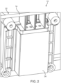
FIG. 2 is another perspective view illustrating a battery charger including a sealed interface according toFIG. 1 . -
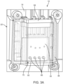
FIG. 3A is a section view illustrating the perspective view of a battery charger including a sealed interface according toFIG. 2 . -
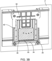
FIG. 3B is a section view illustrating the perspective view of a battery charger including a sealed interface according toFIG. 2 . -
FIG. 4 is a section view illustrating a perspective of a battery charger including a sealed interface according toFIG. 1 . -
FIG. 5 is a section view illustrating a perspective view of a battery charger including a sealed interface according toFIG. 1 . - Before any embodiments of the disclosure are explained in detail, it is to be understood that the subject matter is not limited in its application to the details of construction and the arrangement of components set forth in the following description or illustrated in the following drawings. The subject matter is capable of other embodiments and of being practiced or of being carried out in various ways.
-
FIG. 1 illustrates an embodiment of thebattery charger 10 to which a rechargeable battery (not shown) can be coupled. Thebattery charger 10 includes ahousing 14 that defines acavity 18 containing battery cells, printed circuit board assemblies, or other components configured to electrically recharge a rechargeable battery. Thehousing 14 includes abattery receiving interface 22 which defines arecess 26. Therecess 26 extends inward toward thecavity 18. Aterminal block 30, to which the battery pack is electrically coupled (e.g., by sliding the battery pack relative to thehousing 14 to engage the battery pack with the terminal block 30) when recharging, is disposed in therecess 26. - As shown in
FIG. 2 , areceptacle 34 is coupled to thebattery receiving interface 22, for instance by fasteners (not pictured), such as four screws at corners of thereceptacle 34, which may engagebosses 36 extending from thehousing 14. In other embodiments, thereceptacle 34 may be coupled to thehousing 14 in another manner, such as by snap engagement of thereceptacle 34 with thehousing 14. - As shown in
FIGS. 3A and3B , aseal 38 is interposed between thereceptacle 34 and thebattery receiving interface 22. As illustrated inFIG. 4 , thebattery receiving interface 22,receptacle 34, and seal 38 cooperate to form achamber 42. Thereceptacle 34 includes achannel 46 that extends about a majority of the perimeter of thereceptacle 34. Theseal 38 includes agasket 50 that is disposed in thechannel 46. Thegasket 50 may be overmolded in thechannel 46, that is, formed inside thechannel 46 of thereceptacle 34 by a molding process. Thegasket 50 may instead be manufactured separate from thereceptacle 34 and installed in thechannel 46. Thegasket 50 may be rubber or other elastomeric material, or other material suitable for sealing theinterface 52 between thereceptacle 34 and thebattery receiving interface 22. - The
terminal block 30 includes at least oneterminal fin 54 that extends in a direction away from thereceptacle 34. As shown inFIGS. 3B and4 , thechamber 42 includes a rectangular cross-section in a plane P that is perpendicular to the direction in which theterminal fin 54 extends. Thechannel 46 extends along the plane around at least three side of thechamber 42. Thegasket 50 disposed in thechannel 46 extends along the plane P around at least three sides of thechamber 42. As illustrated inFIG. 5 , theterminal block 30 may be supported by thereceptacle 34, for instance bytabs 56 extending from theterminal block 30 that are supported inslots 57 defined in thereceptacle 34. In other embodiments, theterminal block 30 may be coupled to thehousing 14 in other ways. - With reference to
FIGS. 3A ,3B and4 , in addition to thegasket 50, theseal 38 includes agrommet 58. Thegrommet 58 may be rubber or other elastomeric material, or other material suitable for sealing theinterface 52 between thereceptacle 34 and thebattery receiving interface 22. Thegrommet 58 includes a plurality ofholes 62. A plurality of wires 66 (e.g., four wires) extend from theterminal block 30, through thechamber 42, and through thegrommet 58 to enter thecavity 18. The number ofholes 62 may be equal to the number ofwires 66 that extend through thegrommet 58. Theseal 38 is configured to reduce the amount of fluid entering thecavity 18 such as fluid introduced onto thebattery charger 10. The plurality ofwires 66 may be overmolded in theterminal block 30 for sealing the electrical connection between thewires 66 and theterminal fins 54. - As shown in
FIGS. 3A and4 , apassage 70 is defined between theterminal block 30 and thebattery receiving interface 22. Thepassage 70 is disposed between thebattery receiving interface 22 and theterminal block 30, for instance, below theterminal block 30 opposite theterminal fin 54. Thepassage 70 is in fluid communication with thechamber 42. - With continuing reference to
FIGS 4 and5 , thebattery receiving interface 22 includes anexterior receiving side 104 which receives the battery pack and an oppositeinterior side 108. Thechamber 42 is disposed on theinterior side 108. Thechamber 42 is configured to receive and retain fluid, for instance, water, that has been introduced to thebattery charger 10 at theexterior receiving side 104. By fluidly communicating thechamber 42, thepassage 70 provides an outlet for fluids retained in thechamber 42 to drain from thechamber 42. A battery pack is slidingly coupled to thebattery charger 10 by sliding from anintroduction end 112 to astop end 116, which is opposite theintroduction end 112 of thebattery receiving interface 22. Thepassage 70 is located at a distance from the stop end 116 that is shorter than a distance between thepassage 70 and theintroduction end 112. Thepassage 70 is positioned between theterminal block 30 and thestop end 116. - When used in this specification and claims, the terms "comprises" and "comprising" and variations thereof mean that the specified features, steps or integers are included. The terms are not to be interpreted to exclude the presence of other features, steps or components.
- Representative features are set out in the following clauses, which stand alone or may be combined, in any combination, with one or more features disclosed in the text and/or drawings of the specification.
- 1. A battery charger to which a battery pack may be coupled, the battery charger comprising:
- a housing including a battery receiving interface, the housing defining a cavity, the battery receiving interface defining a recess extending inwardly toward the cavity;
- a terminal block disposed in the recess; and
- a receptacle coupled to the battery receiving interface, the receptacle including a seal interposed between the receptacle and the battery receiving interface,
- wherein the battery receiving interface, the receptacle, and the seal cooperate to form a chamber between the terminal block and the cavity.
- 2. The battery charger of clause 1, wherein the receptacle further includes a channel defined therein, the channel extending about a majority of a perimeter of the chamber, the seal includes a gasket disposed in the channel.
- 3. The battery charger of clause 2, wherein
- the terminal block includes at least one terminal fin extending in a direction away from the receptacle,
- the chamber includes a rectangular cross-section in a plane perpendicular to the direction of the terminal fin, and
- the channel extends along the plane and around at least three sides of the chamber.
- 4. The battery charger of clause 3, wherein the gasket is overmolded on the receptacle.
- 5. The battery charger of clause 2, wherein the seal further includes a grommet.
- 6. The battery charger of clause 5, further including a plurality of wires extending from the terminal block, through the chamber, and through the grommet.
- 7. The battery charger of clause 6, the grommet including a plurality of holes defined therein, each hole corresponding to a respective wire.
- 8. The battery charger of clause 6, wherein the plurality of wires are overmolded in the terminal block.
- 9. The battery charger of clause 1, further comprising a passage defined between the terminal block and the battery receiving interface, the passage in fluid communication with the chamber.
- 10. The battery charger of clause 9, wherein
- the terminal block includes at least one terminal fin, and
- the passage is located on a side of the terminal block opposite the terminal fin.
- 11. The battery charger of clause 1, wherein the receptacle supports the terminal block.
- 12. A battery charger to which a battery pack may be coupled, the battery charger comprising:
- a battery receiving interface, the battery receiving interface having an exterior receiving side and an opposite interior side;
- a chamber disposed on the interior side, the chamber configured to receive and retain fluid introduced to the exterior receiving side of the battery receiving interface;
- a terminal block disposed in the battery receiving interface; and
- a plurality of wires coupled to the terminal block, the plurality of wires extending through the chamber.
- 13. The battery charger of clause 12, wherein the plurality of wires are overmolded in the terminal block.
- 14. The battery charger of clause 12, wherein the battery receiving interface includes
- an introduction end and a stop end opposite the introduction end, and
- a passage defined between the terminal block and the battery receiving interface, a distance between the passage and the stop end is shorter than a distance between the passage and the introduction end, the passage is in fluid communication with the chamber.
- 15. The battery charger of
clause 14, wherein the passage is between the terminal block and the stop end of the battery receiving interface. - 16. The battery charger of clause 15, the battery receiving interface further comprising a sealing interface encompassing the chamber.
- 17. The battery charger of clause 16, the sealing interface including a gasket, the gasket encompassing a majority of the chamber.
- 18. The battery charger of clause 17, wherein the gasket is overmolded with the battery receiving interface.
- 19. The battery charger of clause 16, wherein the sealing interface includes a grommet through which the plurality of wires extend, the grommet being positioned closer to the introduction end than to the stop end.
- 20. A battery charger to which a battery pack may be coupled, the battery charger comprising:
- a housing including a battery receiving interface, the housing defining a cavity, the battery receiving interface defining a recess extending inwardly toward the cavity;
- a terminal block having a plurality of wires extending therefrom, the terminal block disposed in the recess;
- a passage defined between the terminal block and the battery receiving interface;
- a receptacle coupled to the battery receiving interface, the receptacle including a channel defined therein; and
- a seal interposed between the receptacle and the battery receiving interface, the battery receiving interface, the receptacle, and the seal cooperate to form a chamber between the terminal block and cavity, the channel extending about a majority of a perimeter of the chamber, the chamber in fluid communication with the passage, the seal having,
- a gasket disposed in the channel, the gasket being overmolded on the receptacle, and
- a grommet having a plurality of holes through which the plurality of wires extend, the grommet interposed between the receptacle and the housing.
Claims (15)
- A battery charger to which a battery pack may be coupled, the battery charger comprising:a housing including a battery receiving interface, the housing defining a cavity, the battery receiving interface defining a recess extending inwardly toward the cavity;a terminal block disposed in the recess; anda receptacle coupled to the battery receiving interface, the receptacle including a seal interposed between the receptacle and the battery receiving interface,wherein the battery receiving interface, the receptacle, and the seal cooperate to form a chamber between the terminal block and the cavity.
- The battery charger of claim 1, wherein the receptacle further includes a channel defined therein, the channel extending about a majority of a perimeter of the chamber, the seal includes a gasket disposed in the channel.
- The battery charger of claim 2, whereinthe terminal block includes at least one terminal fin extending in a direction away from the receptacle,the chamber includes a rectangular cross-section in a plane perpendicular to the direction of the terminal fin, andthe channel extends along the plane and around at least three sides of the chamber.
- The battery charger of claim 2 or 3, wherein the gasket is overmolded on the receptacle.
- The battery charger of any preceding claim, wherein the seal further includes a grommet, preferably further including a plurality of wires extending from the terminal block, through the chamber, and through the grommet, more preferably the grommet including a plurality of holes defined therein, each hole corresponding to a respective wire.
- The battery charger of claim 5, wherein the plurality of wires are overmolded in the terminal block.
- The battery charger of any preceding claim, further comprising a passage defined between the terminal block and the battery receiving interface, the passage in fluid communication with the chamber and/or wherein the receptacle supports the terminal block.
- The battery charger of claim 7, whereinthe terminal block includes at least one terminal fin, andthe passage is located on a side of the terminal block opposite the terminal fin.
- A battery charger to which a battery pack may be coupled, the battery charger comprising:a battery receiving interface, the battery receiving interface having an exterior receiving side and an opposite interior side;a chamber disposed on the interior side, the chamber configured to receive and retain fluid introduced to the exterior receiving side of the battery receiving interface;a terminal block disposed in the battery receiving interface; anda plurality of wires coupled to the terminal block, the plurality of wires extending through the chamber.
- The battery charger of claim 9, wherein the plurality of wires are overmolded in the terminal block and/or wherein the battery receiving interface includesan introduction end and a stop end opposite the introduction end, anda passage defined between the terminal block and the battery receiving interface, a distance between the passage and the stop end is shorter than a distance between the passage and the introduction end, the passage is in fluid communication with the chamber.
- The battery charger of claim 10, wherein the passage is between the terminal block and the stop end of the battery receiving interface.
- The battery charger of claim 11, the battery receiving interface further comprising a sealing interface encompassing the chamber, preferably the sealing interface including a gasket, the gasket encompassing a majority of the chamber.
- The battery charger of claim 12, wherein the gasket is overmolded with the battery receiving interface.
- The battery charger of claim 12 or 13, wherein the sealing interface includes a grommet through which the plurality of wires extend, the grommet being positioned closer to the introduction end than to the stop end.
- A battery charger to which a battery pack may be coupled, the battery charger comprising:a housing including a battery receiving interface, the housing defining a cavity, the battery receiving interface defining a recess extending inwardly toward the cavity;a terminal block having a plurality of wires extending therefrom, the terminal block disposed in the recess;a passage defined between the terminal block and the battery receiving interface;a receptacle coupled to the battery receiving interface, the receptacle including a channel defined therein; anda seal interposed between the receptacle and the battery receiving interface, the battery receiving interface, the receptacle, and the seal cooperate to form a chamber between the terminal block and cavity, the channel extending about a majority of a perimeter of the chamber, the chamber in fluid communication with the passage, the seal having,a gasket disposed in the channel, the gasket being overmolded on the receptacle, anda grommet having a plurality of holes through which the plurality of wires extend, the grommet interposed between the receptacle and the housing.
Applications Claiming Priority (1)
| Application Number | Priority Date | Filing Date | Title |
|---|---|---|---|
| US202263319421P | 2022-03-14 | 2022-03-14 |
Publications (1)
| Publication Number | Publication Date |
|---|---|
| EP4246764A1 true EP4246764A1 (en) | 2023-09-20 |
Family
ID=85641037
Family Applications (1)
| Application Number | Title | Priority Date | Filing Date |
|---|---|---|---|
| EP23161691.3A Pending EP4246764A1 (en) | 2022-03-14 | 2023-03-14 | Battery charger including a sealed battery interface |
Country Status (3)
| Country | Link |
|---|---|
| US (1) | US20230291215A1 (en) |
| EP (1) | EP4246764A1 (en) |
| CN (1) | CN219739993U (en) |
Families Citing this family (1)
| Publication number | Priority date | Publication date | Assignee | Title |
|---|---|---|---|---|
| WO2026081145A1 (en) * | 2024-10-17 | 2026-04-23 | Gopro, Inc. | Powerpack system |
Citations (1)
| Publication number | Priority date | Publication date | Assignee | Title |
|---|---|---|---|---|
| JP2013192282A (en) * | 2012-03-12 | 2013-09-26 | Max Co Ltd | Charger |
Family Cites Families (5)
| Publication number | Priority date | Publication date | Assignee | Title |
|---|---|---|---|---|
| JP5593200B2 (en) * | 2010-10-27 | 2014-09-17 | 株式会社マキタ | Electric tool system |
| JP2013099119A (en) * | 2011-10-31 | 2013-05-20 | Sanyo Electric Co Ltd | Battery charger |
| US9634503B2 (en) * | 2014-02-26 | 2017-04-25 | Makita Corporation | Battery chargers |
| WO2020184564A1 (en) * | 2019-03-13 | 2020-09-17 | 株式会社オートネットワーク技術研究所 | Battery wiring module and flexible substrate with electronic component |
| WO2022247517A1 (en) * | 2021-05-28 | 2022-12-01 | 格力博(江苏)股份有限公司 | Battery pack, electric tool system, and charging system |
-
2023
- 2023-03-13 US US18/182,599 patent/US20230291215A1/en active Pending
- 2023-03-14 CN CN202320492171.5U patent/CN219739993U/en active Active
- 2023-03-14 EP EP23161691.3A patent/EP4246764A1/en active Pending
Patent Citations (1)
| Publication number | Priority date | Publication date | Assignee | Title |
|---|---|---|---|---|
| JP2013192282A (en) * | 2012-03-12 | 2013-09-26 | Max Co Ltd | Charger |
Also Published As
| Publication number | Publication date |
|---|---|
| CN219739993U (en) | 2023-09-22 |
| US20230291215A1 (en) | 2023-09-14 |
Similar Documents
| Publication | Publication Date | Title |
|---|---|---|
| CN102165625B (en) | Battery module with sealed vent chamber | |
| US20220140523A1 (en) | Header seal for header connector of power connector system | |
| US6365297B1 (en) | High-power bussing connection system for a battery pack | |
| EP3285328B1 (en) | Battery module having improved cooling duct sealing properties | |
| US20160301050A1 (en) | Battery accommodating assembly and power battery module comprising the same | |
| CN210468224U (en) | Electrical connector | |
| CN104953046A (en) | Rechargeable battery having top insulating member | |
| US10123440B2 (en) | Electrical device having a housing and a lid which may be placed on the housing | |
| EP4246764A1 (en) | Battery charger including a sealed battery interface | |
| EP1687865B1 (en) | A method for manufacturing a bipolar battery with a gasket | |
| CN111566868B (en) | Battery cells for battery packs in electric vehicles | |
| CN1764004A (en) | Lithium ion secondary battery | |
| CN117039290A (en) | Cell components and batteries | |
| CN216903471U (en) | Connectors, Batteries and Consumers | |
| CN206558566U (en) | Vehicle mounted dynamic battery | |
| US12095100B2 (en) | Energy-storage apparatus and electricity-consumption device | |
| US20240405310A1 (en) | Assembly with electrical connection through elastomeric gasket | |
| KR101743698B1 (en) | Battery Pack Of Vehicle | |
| CN111916593A (en) | Battery pack, processing system and method for producing battery pack | |
| CN216794039U (en) | Male head of connector, charger, battery and unmanned mobile device | |
| US20190081300A1 (en) | Energy storage apparatus | |
| CN219304355U (en) | Cable buckle and photoelectric sensor with same | |
| CN219759859U (en) | Electrochemical device and electric equipment | |
| CN218005352U (en) | Integrated panel and battery pack | |
| CN219498007U (en) | Battery pack |
Legal Events
| Date | Code | Title | Description |
|---|---|---|---|
| PUAI | Public reference made under article 153(3) epc to a published international application that has entered the european phase |
Free format text: ORIGINAL CODE: 0009012 |
|
| STAA | Information on the status of an ep patent application or granted ep patent |
Free format text: STATUS: REQUEST FOR EXAMINATION WAS MADE |
|
| 17P | Request for examination filed |
Effective date: 20230314 |
|
| AK | Designated contracting states |
Kind code of ref document: A1 Designated state(s): AL AT BE BG CH CY CZ DE DK EE ES FI FR GB GR HR HU IE IS IT LI LT LU LV MC ME MK MT NL NO PL PT RO RS SE SI SK SM TR |