EP4246663A1 - Battery temperature control system - Google Patents
Battery temperature control system Download PDFInfo
- Publication number
- EP4246663A1 EP4246663A1 EP22186889.6A EP22186889A EP4246663A1 EP 4246663 A1 EP4246663 A1 EP 4246663A1 EP 22186889 A EP22186889 A EP 22186889A EP 4246663 A1 EP4246663 A1 EP 4246663A1
- Authority
- EP
- European Patent Office
- Prior art keywords
- temperature
- module
- battery
- battery module
- speed operation
- Prior art date
- Legal status (The legal status is an assumption and is not a legal conclusion. Google has not performed a legal analysis and makes no representation as to the accuracy of the status listed.)
- Pending
Links
- 238000001816 cooling Methods 0.000 claims description 21
- 238000010438 heat treatment Methods 0.000 claims description 20
- 238000010586 diagram Methods 0.000 description 6
- WHXSMMKQMYFTQS-UHFFFAOYSA-N Lithium Chemical compound [Li] WHXSMMKQMYFTQS-UHFFFAOYSA-N 0.000 description 3
- 229910052744 lithium Inorganic materials 0.000 description 3
- 230000002035 prolonged effect Effects 0.000 description 2
- 230000033228 biological regulation Effects 0.000 description 1
- 230000008878 coupling Effects 0.000 description 1
- 238000010168 coupling process Methods 0.000 description 1
- 238000005859 coupling reaction Methods 0.000 description 1
- 238000004146 energy storage Methods 0.000 description 1
- 230000017525 heat dissipation Effects 0.000 description 1
- 230000020169 heat generation Effects 0.000 description 1
- 238000004519 manufacturing process Methods 0.000 description 1
- 238000000034 method Methods 0.000 description 1
- 238000012544 monitoring process Methods 0.000 description 1
- 238000013021 overheating Methods 0.000 description 1
Images





Classifications
-
- H—ELECTRICITY
- H01—ELECTRIC ELEMENTS
- H01M—PROCESSES OR MEANS, e.g. BATTERIES, FOR THE DIRECT CONVERSION OF CHEMICAL ENERGY INTO ELECTRICAL ENERGY
- H01M10/00—Secondary cells; Manufacture thereof
- H01M10/60—Heating or cooling; Temperature control
- H01M10/61—Types of temperature control
-
- H—ELECTRICITY
- H01—ELECTRIC ELEMENTS
- H01M—PROCESSES OR MEANS, e.g. BATTERIES, FOR THE DIRECT CONVERSION OF CHEMICAL ENERGY INTO ELECTRICAL ENERGY
- H01M10/00—Secondary cells; Manufacture thereof
- H01M10/42—Methods or arrangements for servicing or maintenance of secondary cells or secondary half-cells
- H01M10/48—Accumulators combined with arrangements for measuring, testing or indicating the condition of cells, e.g. the level or density of the electrolyte
- H01M10/486—Accumulators combined with arrangements for measuring, testing or indicating the condition of cells, e.g. the level or density of the electrolyte for measuring temperature
-
- H—ELECTRICITY
- H01—ELECTRIC ELEMENTS
- H01M—PROCESSES OR MEANS, e.g. BATTERIES, FOR THE DIRECT CONVERSION OF CHEMICAL ENERGY INTO ELECTRICAL ENERGY
- H01M10/00—Secondary cells; Manufacture thereof
- H01M10/60—Heating or cooling; Temperature control
- H01M10/61—Types of temperature control
- H01M10/613—Cooling or keeping cold
-
- H—ELECTRICITY
- H01—ELECTRIC ELEMENTS
- H01M—PROCESSES OR MEANS, e.g. BATTERIES, FOR THE DIRECT CONVERSION OF CHEMICAL ENERGY INTO ELECTRICAL ENERGY
- H01M10/00—Secondary cells; Manufacture thereof
- H01M10/60—Heating or cooling; Temperature control
- H01M10/61—Types of temperature control
- H01M10/615—Heating or keeping warm
-
- H—ELECTRICITY
- H01—ELECTRIC ELEMENTS
- H01M—PROCESSES OR MEANS, e.g. BATTERIES, FOR THE DIRECT CONVERSION OF CHEMICAL ENERGY INTO ELECTRICAL ENERGY
- H01M10/00—Secondary cells; Manufacture thereof
- H01M10/60—Heating or cooling; Temperature control
- H01M10/63—Control systems
- H01M10/635—Control systems based on ambient temperature
-
- H—ELECTRICITY
- H01—ELECTRIC ELEMENTS
- H01M—PROCESSES OR MEANS, e.g. BATTERIES, FOR THE DIRECT CONVERSION OF CHEMICAL ENERGY INTO ELECTRICAL ENERGY
- H01M10/00—Secondary cells; Manufacture thereof
- H01M10/60—Heating or cooling; Temperature control
- H01M10/65—Means for temperature control structurally associated with the cells
- H01M10/651—Means for temperature control structurally associated with the cells characterised by parameters specified by a numeric value or mathematical formula, e.g. ratios, sizes or concentrations
-
- H—ELECTRICITY
- H01—ELECTRIC ELEMENTS
- H01M—PROCESSES OR MEANS, e.g. BATTERIES, FOR THE DIRECT CONVERSION OF CHEMICAL ENERGY INTO ELECTRICAL ENERGY
- H01M10/00—Secondary cells; Manufacture thereof
- H01M10/60—Heating or cooling; Temperature control
- H01M10/65—Means for temperature control structurally associated with the cells
- H01M10/656—Means for temperature control structurally associated with the cells characterised by the type of heat-exchange fluid
- H01M10/6561—Gases
- H01M10/6563—Gases with forced flow, e.g. by blowers
-
- H—ELECTRICITY
- H01—ELECTRIC ELEMENTS
- H01M—PROCESSES OR MEANS, e.g. BATTERIES, FOR THE DIRECT CONVERSION OF CHEMICAL ENERGY INTO ELECTRICAL ENERGY
- H01M10/00—Secondary cells; Manufacture thereof
- H01M10/60—Heating or cooling; Temperature control
- H01M10/66—Heat-exchange relationships between the cells and other systems, e.g. central heating systems or fuel cells
- H01M10/663—Heat-exchange relationships between the cells and other systems, e.g. central heating systems or fuel cells the system being an air-conditioner or an engine
-
- H—ELECTRICITY
- H01—ELECTRIC ELEMENTS
- H01M—PROCESSES OR MEANS, e.g. BATTERIES, FOR THE DIRECT CONVERSION OF CHEMICAL ENERGY INTO ELECTRICAL ENERGY
- H01M10/00—Secondary cells; Manufacture thereof
- H01M10/60—Heating or cooling; Temperature control
- H01M10/62—Heating or cooling; Temperature control specially adapted for specific applications
- H01M10/627—Stationary installations, e.g. power plant buffering or backup power supplies
-
- Y—GENERAL TAGGING OF NEW TECHNOLOGICAL DEVELOPMENTS; GENERAL TAGGING OF CROSS-SECTIONAL TECHNOLOGIES SPANNING OVER SEVERAL SECTIONS OF THE IPC; TECHNICAL SUBJECTS COVERED BY FORMER USPC CROSS-REFERENCE ART COLLECTIONS [XRACs] AND DIGESTS
- Y02—TECHNOLOGIES OR APPLICATIONS FOR MITIGATION OR ADAPTATION AGAINST CLIMATE CHANGE
- Y02E—REDUCTION OF GREENHOUSE GAS [GHG] EMISSIONS, RELATED TO ENERGY GENERATION, TRANSMISSION OR DISTRIBUTION
- Y02E60/00—Enabling technologies; Technologies with a potential or indirect contribution to GHG emissions mitigation
- Y02E60/10—Energy storage using batteries
Definitions
- the present disclosure relates to a battery temperature control system, and more particularly to a battery temperature control system which can conduct a thermal management to each battery module, respectively.
- a plurality of battery modules are arranged in a battery cabinet, and there are also a plurality of batteries arranged in series in each battery module, wherein these battery modules are thermally managed by an air conditioner.
- the thermal management of the battery module mainly lies in how to enhance the temperature uniformity of the batteries.
- the reasons for the uneven temperature of the batteries include the batteries are produced from different production batches, the different impedance of the batteries themselves, the placement location of the battery module (high or low in the battery cabinet), the uneven internal wind field and the difference between the high or low temperature of the external environment and the sunlit surface, etc.
- the heat generation of each battery is also dynamic, it may generate different amounts of heat according to different currents or times. These factors make the thermal management of the battery modules more difficult, and are hard to handle. Especially, when many battery modules are disposed in the battery cabinet at the same time, it is even more difficult to conduct the thermal management the individual battery modules one by one.
- outdoor battery energy storage cabinets often use an air conditioner for cooling, so that the ambient temperature within the battery cabinet is maintained at 20-30 degrees to avoid overheating of the batteries.
- the ambient temperature is not equal to the battery temperature, and the battery is often wrapped in a complex battery module structure. If the temperature in the cabinet is locally high or low, and the battery module is disposed at the location of local high or low temperature, the battery temperature thereof may be too high or too low.
- the battery module may suspend operation due to perform the protection of the single battery, so that other batteries with normal temperature in the same battery module will not be able to operate, which may result in a loss of total electrical capacity.
- the uneven temperature of the batteries of the prior art may also indirectly affect the service life of the batteries. Namely, it is important that how to enhance the temperature uniformity of the battery modules in the battery cabinet. Therefore, there is a need of providing battery temperature control system to obviate the drawbacks encountered from the prior arts.
- a battery temperature control system including a cabinet, an air conditioner, a central control module and a plurality of battery modules.
- the air conditioner is disposed in the cabinet for providing a cold source or a heat source.
- the central control module is disposed in the cabinet and coupled with the air conditioner.
- the plurality of battery modules are coupled with the central control module, wherein each of the plurality of battery modules includes a plurality of batteries, a control unit, a fan assembly and a temperature detecting module.
- the plurality of batteries, the fan assembly and the temperature detecting module are coupled with the control unit.
- Each battery module is constructed in a case, and the case is received in the cabinet.
- the temperature detecting module of each battery module detects and monitors a working temperature of the corresponding battery module continuously, and sends a working temperature information to the central control module.
- the central control module sends a temperature controlling command to the air conditioner to activate the cold source or the heat source according to an ambient temperature. Then the central control module compares and calculates the working temperature information transmitted from the plurality of battery modules, and sends a fan operation command to the corresponding battery module.
- the corresponding fan assembly activates an operation mode to cool down or heat up the corresponding battery module, so as to adjust the working temperature of each battery module to achieve a dynamic temperature balance.
- the air conditioner includes a cooling module and a heating module for respectively providing the cold source and the heat source, and outputting a cold air and a hot air.
- the temperature controlling command includes a first temperature controlling command and a second temperature controlling command.
- the central control module sends the first temperature controlling command to the air conditioner to activate the cooling module, so as to provide the cold source and output the cold air.
- the central control module sends the second temperature controlling command to the air conditioner to activate the heating module, so as to provide the heat source and output the hot air.
- the working temperature of each battery module is a first average temperature of the plurality of batteries of the battery module.
- the central control module calculates and compares the plurality of working temperature information transmitted from the plurality of battery modules with a reference temperature to calculate a deviation value of each battery module, and sends the fan operation command to the each corresponding battery module according to a working mode of the air conditioner and whether the deviation value exceeds a predetermined value, so that the fan assembly activates the operation mode to cool down or heat up the corresponding battery module to adjust the working temperature of each battery module.
- the reference temperature is a second average temperature of the plurality of battery module.
- the fan operation command includes a high-speed operation command, a medium-speed operation command and a low-speed operation command.
- the operation mode of the fan assembly includes a high-speed operation mode, a medium-speed operation mode and a low-speed operation mode.
- the control unit of the battery module receives and sends the high-speed operation command, the medium-speed operation command or the low-speed operation command to the fan assembly, the fan assembly can correspondingly activate the high-speed operation mode, the medium-speed operation mode, or the low-speed operation mode.
- the central control module when the working mode of the air conditioner is a cooling mode, and the deviation value is a positive number and higher than the predetermined value, the central control module will transmit the high-speed operation command to the corresponding battery module, and the fan assembly will correspondingly activate the high-speed operation mode, so as to cool down the plurality of batteries of the battery module to reduce the working temperature of the battery module.
- the central control module when the working mode of the air conditioner is a cooling mode, and the deviation value is a negative number and higher than the predetermined value, the central control module will transmit the low-speed operation command to the corresponding battery module, and the fan assembly will correspondingly activate the low-speed operation mode, so as to decrease the cooling efficiency.
- the central control module when the deviation value is lower than the predetermined value, the central control module will transmit the medium-speed operation command to the corresponding battery module, and the fan assembly will correspondingly activate the medium-speed operation mode, so as to maintain the working temperature of the battery module.
- the central control module when the working mode of the air conditioner is a heating mode, and the deviation value is a positive number and higher than the predetermined value, the central control module will transmit the low-speed operation command to the corresponding battery module, and the fan assembly will correspondingly activate the low-speed operation mode, so as to decrease the heating efficiency.
- the central control module when the working mode of the air conditioner is a heating mode, and the deviation value is a negative number and higher than the predetermined value, the central control module will transmit the high-speed operation command to the corresponding battery module, and the fan assembly will correspondingly activate the high-speed operation mode, so as to heat up the plurality of batteries of the battery module to increase the working temperature of the battery module.
- FIG. 1 is a block diagram illustrating a battery temperature control system according to an embodiment of the present disclosure.
- FIG. 2 is a schematic perspective view illustrating a cabinet of the battery temperature control system of FIG. 1 .
- FIG. 3 is a block diagram illustrating a central control module of the battery temperature control system of FIG. 1 .
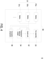
- FIG. 4 is a block diagram illustrating a battery module of the battery temperature control system of FIG. 1 .
- the battery temperature control system 1 includes a cabinet 2, an air conditioner 3, a central control module 4 and a plurality of battery module 5.
- the air conditioner 3 is disposed in the cabinet 2, and includes a cooling module 31 and a heating module 32 so as to provide a cold source and a heat source, respectively.
- the central control module 4 is disposed in the cabinet 2 and couples with the air conditioner 3.
- the plurality of battery modules 5 are coupled with the central control module 4.
- each of the plurality of battery modules 5 includes a plurality of batteries 51, a control unit 52, a fan assembly 53 and a temperature detecting module 54, wherein the plurality of batteries 51, the fan assembly 53 and the temperature detecting module 54 are coupled with the control unit 52, and each battery module 5 is constructed in a case 50, the case 50 is received in the cabinet 2.
- the temperature detecting module 54 of each battery module 5 detects and monitors a working temperature of the corresponding battery module 5 continuously, and sends a working temperature information to the central control module 4.
- the central control module 4 sends a temperature controlling command to the air conditioner 3 to activate the cold source or the heat source according to an ambient temperature, then the central control module 4 compares and calculates the working temperature information transmitted from the plurality of battery modules 5, and sends a fan operation command to the corresponding battery module 5.
- the fan assembly 53 of the corresponding battery module 5 activates an operation mode to cool down or heat up the corresponding battery module 5, so as to adjust the working temperature of each battery module 5 to achieve a dynamic temperature balance.
- the air conditioner 3, the central control module 4 and the plurality of battery modules 5 are all disposed within the cabinet 2.
- the cabinet 2 is a large cabinet, taking this embodiment as an example, the plurality of battery modules 5A, 5B, 5C, 5D... are arranged side by side, and the number is 18. It is noted that the arrangement and number are not limited thereto and are adjustable according to the practical requirements.
- the air conditioner 3 is placed in the front side of the cabinet 2. In one embodiment, the air conditioner 3 may be hung on the door of the cabinet 2, but not limited to. In another embodiment, the air conditioner 3 may be disposed in the rare side of the cabinet 2 or disposed out of the cabinet 2.
- the disposed position and number of the air conditioner 3 are not limited thereto and are adjustable according the practical requirements.
- the air conditioner 3 can be a generally commercially available air conditioner, wherein the controller, the temperature sensor and the connector thereof are omitted here, which is mainly used for providing the cold source or the heat source of the battery temperature control system 1, therefore the types of the temperature adjustment device are not limited thereto.
- the air conditioner 3 includes the cooling module 31 and the heating module 32 at the same time, so that it can be chosen to provide the cold source or the heat source according to the temperature controlling command transmitted from the central control module 4, and then output cold air or hot air, respectively.
- the central control module 4 is stacked on the plurality of battery modules 5, but the position is not limited thereto.
- the central control module 4 includes a main board 40, a core processor 41, a memory unit 42, and a connecting module 43, wherein the core processor 41, the memory unit 42, and the connecting module 43 are electrically coupled with each other, and are disposed on the main board 40.
- the memory unit 42 is configured for storing reference temperature information.
- the connecting module 43 includes a plurality of connectors (not shown) for coupling with the air conditioner 3 and the plurality of battery modules 5 correspondingly.
- the central control module 4 further includes at least one temperature sensor (not shown) for detecting the ambient temperature inside the cabinet 2, and sending the ambient temperature information to the core processor 41.
- the ambient temperature inside the cabinet 2 may be calculated from the plurality working temperature information of the plurality of battery modules 5, but not limited to.
- the core processor 41 is configured for receiving, comparing and calculating information, determining and then outputting the corresponding commend.
- the core processor 41 evaluates, determines and sends a corresponding temperature controlling command to the air conditioner 3 through the connecting module 43, so that the air conditioner 3 can activate the corresponding working mode, for example, cooling mode or heating mode, to output cold air or hot air to adjust temperature, so as to achieve a dynamic temperature balance inside the cabinet 2.
- the temperature controlling command includes a first temperature controlling command and a second temperature controlling command.
- the core processor 41 of the central control module 4 sends the first temperature controlling command to the air conditioner 3.
- the first temperature controlling command is to activate the cooling module 31 of the air conditioner 3, so as to provide the cold source and output cold air. Consequently, the plurality of battery modules 5 disposed inside the cabinet 2 can inhale the cold air to cool down.
- the core processor 41 of the central control module 4 sends the second temperature controlling command to the air conditioner 3 to activate the heating module 32 of the air conditioner 3, so as to provide the heat source and output hot air. Consequently, the plurality of battery modules 5 disposed inside the cabinet 2 can inhale the hot air to heat up.
- the core processor 41 also sends a fan operation command to the corresponding battery module 5 through the connecting module 43 according to the working mode of the air conditioner 3 and whether the deviation value exceeds a predetermined value, so that the fan assembly 53 activates the operation mode to cool down or heat up the plurality of batteries 51 to adjust the working temperature of the corresponding battery module 5.
- the fan operation command includes a high-speed operation command, a medium-speed operation command and a low-speed operation command, wherein the fan assembly 53 of each battery module 5 can correspondingly activate a high-speed operation mode, a medium-speed operation mode, and a low-speed operation mode according to the high-speed operation command, the medium-speed operation command and the low-speed operation command, respectively.
- FIG. 5 is a schematic perspective view illustrating the battery module of the battery temperature control system of FIG. 1 from one angle.
- FIG. 6A is a schematic perspective view illustrating the battery module of the battery temperature control system of FIG. 5 from another angle.
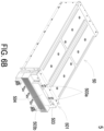
- FIG. 6B is a bottom schematic perspective view illustrating the battery module of FIG. 6A .
- each battery module 5 includes a plurality of batteries 51a, 51b, 51c, etc., a control unit 52, a fan assembly 53, a temperature detecting module 54 and a connection component 56, wherein the plurality of batteries 51a, 51b, 51c...
- the control unit 52 the temperature detecting module 54 and the connection component 56, so as to transport power produced from the plurality of batteries 51a, 51b, 51c... through the connection component 56.
- the fan assembly 53, the temperature detecting module 54 and the connection component 56 are also coupled with the control unit 52.
- the temperature detecting module 54 detects the temperature of each battery 51, and then transmits the temperature information of the plurality of batteries 51a, 51b, 51c... to the control unit 52 to calculate and output a working temperature of the battery module 5.
- each battery module 5 is constructed in a case 50, and the case 50 is received in the cabinet 2.
- the case 50 is a square box structure, and can be drawn out and accommodated in the cabinet 2 in a drawer type, but is not limited thereto.
- the case 50 has four side surfaces corresponding to each other, wherein the first side surface 502 and the second side surface 503 are respectively disposed on the first side 500 and the second side 501.
- the first side 500 and the second side 501 correspond to each other.
- the first side 500 and the second side 501 are the front side and the rear side, respectively.
- the first side 500 is disposed on the front side, and is adjacent to the air conditioner 3 disposed on the door of the cabinet 2. Since the first side 500 is the front side of the cabinet 2, the second side 501 is corresponding to the rear side of the cabinet 2.
- a first opening 502a is disposed on the first side surface 502 of the first side 500.
- the first opening 502a can be but not limited to a hollowed-out narrow hole vertically running through the center of the first side 500 for allowing cold air or hot air to flow into the battery module 5, so as to adjust the temperature of the battery module 5.
- the types, arrangement and number of the first opening 502a are not limited thereto and are adjustable according to the practical requirements.
- the second side surface 503 is disposed on the second side 501 corresponding to the first side 500.
- a plurality of second openings 503a (as shown in FIG. 6B ) and a plurality of third openings 503b are disposed on the second side surface 503.
- the second opening 503a is disposed below the extending portion 504 of the second side surface 503, and the position of the second opening 503a is shown as the bottom schematic perspective view of FIG. 6B .
- the number of the second openings 503a is two, and the second openings 503a are configured for allowing the hot air inside the battery module 5 to flow out.
- the third openings 503b are fence-type opening structures transversely extending through the second side surface 503, and the position of the third openings 503b are corresponding to the fan assembly 53 inside, so that the fan assembly 53 can discharge the forced convection hot air to the outside of the battery module 5.
- the types, arrangement and number of the second openings 503a and the third openings 503b are not limited thereto and are adjustable according to the practical requirements.
- FIG. 7 is a schematic perspective view illustrating the inner structure of the battery module of FIG. 6A .
- a plurality of batteries 51a, 51b, 51c... are disposed inside the battery module 5.
- the plurality of batteries 51a, 51b, 51c... are arranged side by side.
- the battery module 5 includes two rows of batteries 51, and the number of batteries 51 in each row is 11, so that the battery module 5 of the present disclosure includes 22 batteries 51 in total, but the number of the batteries 51 can be adjusted according to the practical requirements.
- the fan assembly 53 is disposed at the second side 501 of the battery module 5.
- the fan assembly 53 includes two fans 53a and 53b.
- the fans 53a and 53b are symmetrically arranged on the corresponding two sides of the second side 501.
- the positions of the fans 53a and 53b are in correspondence with the two rows of batteries 51, so as to dissipate heat of the corresponding row of the batteries 51, respectively.
- the number and positions of the fans 53a and 53b of the fan assembly 53 are not limited thereto.
- the control unit 52 of the battery module 5 is disposed on a circuit board 55, and the circuit board 55 is correspondingly disposed between the two fans 53a, 53b, but not limited thereto.
- the temperature detecting module 54 includes a plurality of temperature sensors (not shown), which are respectively arranged inside the case 50 and corresponding to the plurality of batteries 51a, 51b, 51c..., so as to detect and monitor the temperature of each battery 51a, 51b, 51c... of the battery module 5, and transmit the temperature information of the plurality of batteries 51a, 51b, 51c... to the control unit 52 disposed on the circuit board 55. Consequently, a working temperature of the battery module 5 can be calculated accordingly.
- the working temperature of each battery module 5 is an average temperature of the plurality of batteries 51 of the battery module 5, which is a first average temperature.
- connection component 56 may be but not limited to a connector for transmitting signals, or an electrical connector for transmitting power, etc., so as to transmit the working temperature information monitored by the battery module 5 to the central control module 4, or transmit the power supplied by the plurality of batteries 51 of the battery module 5.
- the temperature detecting module 54 of each battery module 5 continuously monitors the temperature of each battery 51 through the plurality of temperature sensors, and transmits the monitoring temperature information to the control unit 52 of the battery module 5, so as to obtain the working temperature information (i.e., the first average temperature) of the battery module 5. Then, the working temperature information of each battery module 5 is transmitted to the central control module 4 through the connection component 56, and the central control module 4 compares it with a reference temperature. Consequently, a deviation value between the working temperature of each battery module 5 and the reference temperature is obtained.
- the reference temperature is a second average temperature of the plurality of battery modules 5A, 5B, 5C, 5D.
- each battery module 5A, 5B, 5C, 5D ... respectively transmits the working temperature information (i.e., the first average temperature) monitored by the temperature detecting module 54 to the central control module 4, the core processor 41 calculates the currently average temperature of the plurality of battery modules 5A, 5B, 5C, 5D..., which is the second average temperature, and is used as the reference temperature for temperature regulation.
- the working temperature information i.e., the first average temperature
- the core processor 41 calculates the currently average temperature of the plurality of battery modules 5A, 5B, 5C, 5D..., which is the second average temperature, and is used as the reference temperature for temperature regulation.
- the thermal management of the plurality of battery modules 5A, 5B, 5C, 5D... is dynamic thermal management, which is mainly based on the current working mode (cooling mode or heating mode) of the air conditioner 3 and whether the above deviation value exceeds a predetermined value, thereby conducting the thermal management of the plurality of battery modules 5A, 5B, 5C, 5D..., respectively.
- the core processor 41 of the central control module 4 transmits a high-speed operation command to the corresponding battery module 5A.
- the tolerance range of the deviation value is below 5 °C, but not limited to.
- the control unit 52 of the battery module 5A controls the fan assembly 53 to activate the high-speed operation mode according to the high-speed operation command, so as to cool down the plurality of batteries 51 of the battery module 5A to reduce the working temperature of the battery module 5A. Consequently, the deviation value can be adjusted into the tolerance range of the predetermined value.
- the fan assembly 53 of the battery module 5A executes the high-speed operation mode
- the fan assembly 53 conducts the forced heat dissipation to the plurality of batteries 51 in the battery module 5A.
- the heat generated by the plurality of batteries 51 is rapidly transported outward from the plurality of second openings 503a and the third openings 503b on the second side surface 503 through the high-speed operation mode of the fans 53a, 53b.
- the cold air provided by the cold source of the air conditioner 3 can quickly be introduced into the battery module 5A through the first opening 502a on the first side surface 502.
- the cold air flows through the plurality of batteries 51 in sequence to dissipate heat of the plurality of batteries 51, so as to reduce the working temperature of the battery module 5A.
- the temperature detecting module 54 continuously monitors the working temperature of battery module 5A, and transmits the working temperature information to the central control module 4 through the control unit 52 of the battery module 5, so as to conduct the calculation again. If the deviation value between the working temperature of the battery module 5A and the reference temperature (i.e., the second average temperature) falls within the predetermined value (i.e., 5°C) after the above-mentioned temperature control procedure, the central control module 4 transmits the medium-speed operation command to the battery module 5A.
- the control unit 52 of the battery module 5A After the control unit 52 of the battery module 5A receives the medium-speed operation command, the control unit 52 transmits the medium-speed operation command to the fan assembly 53 to activate the corresponding medium-speed operation mode. Consequently, the rotational speeds of the fans 53a, 53b are reduced to a medium speed to slow down the speed of transporting cold air into the battery module 5A. Consequently, the cooling speed of the battery module 5A is slowed down, and the working temperature is maintained.
- the air conditioner 3 is a cooling mode, and the deviation value is a negative number and higher than the predetermined value (5°C)
- the deviation value between the working temperature of the battery module 5A and the reference temperature i.e., the second average temperature
- the central control module 4 transmits the low-speed operation command to the battery module 5A, so that the control unit 52 transmits the low-speed operation command to the fan assembly 53 to activate the corresponding low-speed operation mode. Consequently, the rotational speeds of the fans 53a, 53b are reduced to a low speed, and the cold air is transported into the battery module 5A in a small amount to reduce the cooling capacity.
- the core processor 41 of the central control module 4 transmits the low-speed operation command to the corresponding battery module 5B.
- the control unit 52 of battery module 5B controls the fan assembly 53 to activate the corresponding low-speed operation mode according to the low-speed operation command. Consequently, the rotational speeds of the fans 53a, 53b are reduced to the low speed, and the hot air is transported into the battery module 5B in a small amount to decrease the heating efficiency.
- the central control module 4 transmits the high-speed operation command to the corresponding battery module 5B, so that the control unit 52 transmits the high-speed operation command to the fan assembly 53 to activate the corresponding high-speed operation mode. Consequently, the rotational speeds of the fans 53a, 53b are increased to a high speed, and the hot air is largely and rapidly transported into the battery module 5B, so as to heat up the plurality of batteries 51 of the battery module 5B to raise the working temperature of the battery module 5B. Consequently, the deviation value is adjusted into the tolerance range of the predetermined value.
- the central control module 4 transmits the medium-speed operation command to the battery module 5B, wherein the fan assembly 53 of the battery module 5B can activate the corresponding medium-speed operation mode, so as to slow down the speed of transporting hot air into the battery module 5B, thereby slowing down the heating speed of the battery module 5B and maintaining the working temperature of the battery module 5B.
- the thermal management of the plurality of battery modules 5A, 5B, 5C, 5D... is a dynamic thermal management.
- the different fan operation command is sent to the fan assembly 53 of the corresponding battery modules 5A, 5B, etc. to perform different fan speed adjustments.
- the working temperature of the battery modules 5A, 5B can be lowered or raised, and the working temperature of the battery modules 5A, 5B can be brought back to the average value, so as to maintain the temperature consistency of the battery modules 5A, 5B, 5C, 5D, etc. Meanwhile, the temperature uniformity of the plurality of batteries 51 in each battery module 5 is improved, thereby effectively prolonging the service life of the batteries 51 and preventing the loss of the total electric capacity.
- the present disclosure provides a battery temperature control system, wherein the central control module sends a temperature controlling command to the air conditioner to activate a cold source or a heat source according to an ambient temperature. Then the central control module compares and calculates the working temperature information transmitted from the plurality of battery modules of a cabinet, and sends a fan operation command to each corresponding battery module.
- the fan assembly of each corresponding battery module activates an operation mode to cool down or heat up the plurality of batteries of the corresponding battery module, so as to adjust the working temperature of each battery module to achieve a dynamic temperature balance. Consequently, the cooling efficiency or heating efficiency of each battery module of the cabinet is increased, the temperature uniformity of the plurality of batteries is improved, the service life of the batteries is effectively prolonged, the loss of the total electric capacity is prevented, and the product reliability is also increased.
Landscapes
- Engineering & Computer Science (AREA)
- Manufacturing & Machinery (AREA)
- Chemical & Material Sciences (AREA)
- Chemical Kinetics & Catalysis (AREA)
- Electrochemistry (AREA)
- General Chemical & Material Sciences (AREA)
- General Physics & Mathematics (AREA)
- Physics & Mathematics (AREA)
- Algebra (AREA)
- Mathematical Analysis (AREA)
- Mathematical Optimization (AREA)
- Pure & Applied Mathematics (AREA)
- Automation & Control Theory (AREA)
- Secondary Cells (AREA)
Abstract
Description
- The present disclosure relates to a battery temperature control system, and more particularly to a battery temperature control system which can conduct a thermal management to each battery module, respectively.
- With the wide application of lithium batteries and the continuous improvement of the voltage requirements, the number of lithium batteries placed in a usual battery cabinet can easily exceed 200, or more. Such a huge number of lithium batteries makes it difficult to control the thermal management of these batteries. Generally speaking, a plurality of battery modules are arranged in a battery cabinet, and there are also a plurality of batteries arranged in series in each battery module, wherein these battery modules are thermally managed by an air conditioner.
- The thermal management of the battery module mainly lies in how to enhance the temperature uniformity of the batteries. In the prior art, the reasons for the uneven temperature of the batteries include the batteries are produced from different production batches, the different impedance of the batteries themselves, the placement location of the battery module (high or low in the battery cabinet), the uneven internal wind field and the difference between the high or low temperature of the external environment and the sunlit surface, etc. In addition, since the heat generation of each battery is also dynamic, it may generate different amounts of heat according to different currents or times. These factors make the thermal management of the battery modules more difficult, and are hard to handle. Especially, when many battery modules are disposed in the battery cabinet at the same time, it is even more difficult to conduct the thermal management the individual battery modules one by one.
- In the prior art, outdoor battery energy storage cabinets often use an air conditioner for cooling, so that the ambient temperature within the battery cabinet is maintained at 20-30 degrees to avoid overheating of the batteries. However, the ambient temperature is not equal to the battery temperature, and the battery is often wrapped in a complex battery module structure. If the temperature in the cabinet is locally high or low, and the battery module is disposed at the location of local high or low temperature, the battery temperature thereof may be too high or too low. Moreover, if the temperature of a single battery is too high or too low, and exceeds its predetermined protection value, the battery module may suspend operation due to perform the protection of the single battery, so that other batteries with normal temperature in the same battery module will not be able to operate, which may result in a loss of total electrical capacity.
- In addition, the uneven temperature of the batteries of the prior art may also indirectly affect the service life of the batteries. Namely, it is important that how to enhance the temperature uniformity of the battery modules in the battery cabinet. Therefore, there is a need of providing battery temperature control system to obviate the drawbacks encountered from the prior arts.
- It is an object of the present disclosure to provide a battery temperature control system, which can provide a cold source or a heat source for a plurality of battery modules, and can also conduct a thermal management to each battery module, respectively. It can effectively target the battery modules that deviate from the average, so as to cool down or heat up the deviated battery modules. Consequently, the working temperature of each battery module is adjusted, the temperature uniformity of the battery modules is improved, the service life of the batteries is prolonged, and the reliability of the product is improved.
- In accordance with an aspect of the present disclosure, there is provided a battery temperature control system including a cabinet, an air conditioner, a central control module and a plurality of battery modules. The air conditioner is disposed in the cabinet for providing a cold source or a heat source. The central control module is disposed in the cabinet and coupled with the air conditioner. The plurality of battery modules are coupled with the central control module, wherein each of the plurality of battery modules includes a plurality of batteries, a control unit, a fan assembly and a temperature detecting module. The plurality of batteries, the fan assembly and the temperature detecting module are coupled with the control unit. Each battery module is constructed in a case, and the case is received in the cabinet. The temperature detecting module of each battery module detects and monitors a working temperature of the corresponding battery module continuously, and sends a working temperature information to the central control module. The central control module sends a temperature controlling command to the air conditioner to activate the cold source or the heat source according to an ambient temperature. Then the central control module compares and calculates the working temperature information transmitted from the plurality of battery modules, and sends a fan operation command to the corresponding battery module. The corresponding fan assembly activates an operation mode to cool down or heat up the corresponding battery module, so as to adjust the working temperature of each battery module to achieve a dynamic temperature balance.
- In an embodiment, the air conditioner includes a cooling module and a heating module for respectively providing the cold source and the heat source, and outputting a cold air and a hot air.
- In an embodiment, the temperature controlling command includes a first temperature controlling command and a second temperature controlling command. When the ambient temperature is determined as in a high temperature state, the central control module sends the first temperature controlling command to the air conditioner to activate the cooling module, so as to provide the cold source and output the cold air. When the ambient temperature is determined as in a low temperature state, the central control module sends the second temperature controlling command to the air conditioner to activate the heating module, so as to provide the heat source and output the hot air.
- In an embodiment, the working temperature of each battery module is a first average temperature of the plurality of batteries of the battery module.
- In an embodiment, the central control module calculates and compares the plurality of working temperature information transmitted from the plurality of battery modules with a reference temperature to calculate a deviation value of each battery module, and sends the fan operation command to the each corresponding battery module according to a working mode of the air conditioner and whether the deviation value exceeds a predetermined value, so that the fan assembly activates the operation mode to cool down or heat up the corresponding battery module to adjust the working temperature of each battery module.
- In an embodiment, the reference temperature is a second average temperature of the plurality of battery module.
- In an embodiment, the fan operation command includes a high-speed operation command, a medium-speed operation command and a low-speed operation command.
- In an embodiment, the operation mode of the fan assembly includes a high-speed operation mode, a medium-speed operation mode and a low-speed operation mode. When the control unit of the battery module receives and sends the high-speed operation command, the medium-speed operation command or the low-speed operation command to the fan assembly, the fan assembly can correspondingly activate the high-speed operation mode, the medium-speed operation mode, or the low-speed operation mode.
- In an embodiment, when the working mode of the air conditioner is a cooling mode, and the deviation value is a positive number and higher than the predetermined value, the central control module will transmit the high-speed operation command to the corresponding battery module, and the fan assembly will correspondingly activate the high-speed operation mode, so as to cool down the plurality of batteries of the battery module to reduce the working temperature of the battery module.
- In an embodiment, when the working mode of the air conditioner is a cooling mode, and the deviation value is a negative number and higher than the predetermined value, the central control module will transmit the low-speed operation command to the corresponding battery module, and the fan assembly will correspondingly activate the low-speed operation mode, so as to decrease the cooling efficiency.
- In an embodiment, when the deviation value is lower than the predetermined value, the central control module will transmit the medium-speed operation command to the corresponding battery module, and the fan assembly will correspondingly activate the medium-speed operation mode, so as to maintain the working temperature of the battery module.
- In an embodiment, when the working mode of the air conditioner is a heating mode, and the deviation value is a positive number and higher than the predetermined value, the central control module will transmit the low-speed operation command to the corresponding battery module, and the fan assembly will correspondingly activate the low-speed operation mode, so as to decrease the heating efficiency.
- In an embodiment, when the working mode of the air conditioner is a heating mode, and the deviation value is a negative number and higher than the predetermined value, the central control module will transmit the high-speed operation command to the corresponding battery module, and the fan assembly will correspondingly activate the high-speed operation mode, so as to heat up the plurality of batteries of the battery module to increase the working temperature of the battery module.
- The above contents of the present invention will become more readily apparent to those ordinarily skilled in the art after reviewing the following detailed description and accompanying drawings, in which:
-
-
FIG. 1 is a block diagram illustrating a battery temperature control system according to an embodiment of the present disclosure; -
FIG. 2 is a schematic perspective view illustrating a cabinet of the battery temperature control system ofFIG. 1 ; -
FIG. 3 is a block diagram illustrating a central control module of the battery temperature control system ofFIG. 1 ; -
FIG. 4 is a block diagram illustrating a battery module of the battery temperature control system ofFIG. 1 ; -
FIG. 5 is a schematic perspective view illustrating the battery module of the battery temperature control system ofFIG. 1 from one angle; -
FIG. 6A is a schematic perspective view illustrating the battery module of the battery temperature control system ofFIG. 5 from another angle; -
FIG. 6B is a bottom schematic perspective view illustrating the battery module ofFIG. 6A ; and -
FIG. 7 is a schematic perspective view illustrating the inner structure of the battery module ofFIG. 6A . - The present invention will now be described more specifically with reference to the following embodiments. It is to be noted that the following descriptions of preferred embodiments of this invention are presented herein for purpose of illustration and description only. It is not intended to be exhaustive or to be limited to the precise form disclosed.
-
FIG. 1 is a block diagram illustrating a battery temperature control system according to an embodiment of the present disclosure.FIG. 2 is a schematic perspective view illustrating a cabinet of the battery temperature control system ofFIG. 1 .FIG. 3 is a block diagram illustrating a central control module of the battery temperature control system ofFIG. 1 .FIG. 4 is a block diagram illustrating a battery module of the battery temperature control system ofFIG. 1 . As shown inFIG. 1 andFIG. 2 , the batterytemperature control system 1 includes acabinet 2, anair conditioner 3, acentral control module 4 and a plurality ofbattery module 5. Theair conditioner 3 is disposed in thecabinet 2, and includes acooling module 31 and aheating module 32 so as to provide a cold source and a heat source, respectively. Thecentral control module 4 is disposed in thecabinet 2 and couples with theair conditioner 3. The plurality ofbattery modules 5 are coupled with thecentral control module 4. As shown onFIG. 4 , each of the plurality ofbattery modules 5 includes a plurality ofbatteries 51, acontrol unit 52, afan assembly 53 and atemperature detecting module 54, wherein the plurality ofbatteries 51, thefan assembly 53 and thetemperature detecting module 54 are coupled with thecontrol unit 52, and eachbattery module 5 is constructed in acase 50, thecase 50 is received in thecabinet 2. Thetemperature detecting module 54 of eachbattery module 5 detects and monitors a working temperature of thecorresponding battery module 5 continuously, and sends a working temperature information to thecentral control module 4. In the embodiment, thecentral control module 4 sends a temperature controlling command to theair conditioner 3 to activate the cold source or the heat source according to an ambient temperature, then thecentral control module 4 compares and calculates the working temperature information transmitted from the plurality ofbattery modules 5, and sends a fan operation command to thecorresponding battery module 5. Thefan assembly 53 of thecorresponding battery module 5 activates an operation mode to cool down or heat up thecorresponding battery module 5, so as to adjust the working temperature of eachbattery module 5 to achieve a dynamic temperature balance. - Please refer to
FIG.1 ,FIG. 2 andFIG. 3 again. In this embodiment, theair conditioner 3, thecentral control module 4 and the plurality ofbattery modules 5 are all disposed within thecabinet 2. As shown inFIG. 2 , thecabinet 2 is a large cabinet, taking this embodiment as an example, the plurality ofbattery modules air conditioner 3 is placed in the front side of thecabinet 2. In one embodiment, theair conditioner 3 may be hung on the door of thecabinet 2, but not limited to. In another embodiment, theair conditioner 3 may be disposed in the rare side of thecabinet 2 or disposed out of thecabinet 2. It is noted that the disposed position and number of theair conditioner 3 are not limited thereto and are adjustable according the practical requirements. In some embodiments, theair conditioner 3 can be a generally commercially available air conditioner, wherein the controller, the temperature sensor and the connector thereof are omitted here, which is mainly used for providing the cold source or the heat source of the batterytemperature control system 1, therefore the types of the temperature adjustment device are not limited thereto. In the embodiment, as shown inFIG. 1 , theair conditioner 3 includes thecooling module 31 and theheating module 32 at the same time, so that it can be chosen to provide the cold source or the heat source according to the temperature controlling command transmitted from thecentral control module 4, and then output cold air or hot air, respectively. - As shown in
FIG. 2 , thecentral control module 4 is stacked on the plurality ofbattery modules 5, but the position is not limited thereto. Moreover, as shown inFIG. 3 , thecentral control module 4 includes amain board 40, acore processor 41, amemory unit 42, and a connectingmodule 43, wherein thecore processor 41, thememory unit 42, and the connectingmodule 43 are electrically coupled with each other, and are disposed on themain board 40. Thememory unit 42 is configured for storing reference temperature information. The connectingmodule 43 includes a plurality of connectors (not shown) for coupling with theair conditioner 3 and the plurality ofbattery modules 5 correspondingly. In some embodiments, thecentral control module 4 further includes at least one temperature sensor (not shown) for detecting the ambient temperature inside thecabinet 2, and sending the ambient temperature information to thecore processor 41. In other embodiments, the ambient temperature inside thecabinet 2 may be calculated from the plurality working temperature information of the plurality ofbattery modules 5, but not limited to. - In the embodiment, the
core processor 41 is configured for receiving, comparing and calculating information, determining and then outputting the corresponding commend. In other words, when thecore processor 41 receives the ambient temperature information, thecore processor 41 evaluates, determines and sends a corresponding temperature controlling command to theair conditioner 3 through the connectingmodule 43, so that theair conditioner 3 can activate the corresponding working mode, for example, cooling mode or heating mode, to output cold air or hot air to adjust temperature, so as to achieve a dynamic temperature balance inside thecabinet 2. In the embodiment, the temperature controlling command includes a first temperature controlling command and a second temperature controlling command. When the ambient temperature is determined as in a high temperature state, thecore processor 41 of thecentral control module 4 sends the first temperature controlling command to theair conditioner 3. The first temperature controlling command is to activate thecooling module 31 of theair conditioner 3, so as to provide the cold source and output cold air. Consequently, the plurality ofbattery modules 5 disposed inside thecabinet 2 can inhale the cold air to cool down. On the contrary, when the ambient temperature is determined as in a low temperature state, thecore processor 41 of thecentral control module 4 sends the second temperature controlling command to theair conditioner 3 to activate theheating module 32 of theair conditioner 3, so as to provide the heat source and output hot air. Consequently, the plurality ofbattery modules 5 disposed inside thecabinet 2 can inhale the hot air to heat up. Besides, thecore processor 41 also sends a fan operation command to thecorresponding battery module 5 through the connectingmodule 43 according to the working mode of theair conditioner 3 and whether the deviation value exceeds a predetermined value, so that thefan assembly 53 activates the operation mode to cool down or heat up the plurality ofbatteries 51 to adjust the working temperature of thecorresponding battery module 5. In the embodiment, the fan operation command includes a high-speed operation command, a medium-speed operation command and a low-speed operation command, wherein thefan assembly 53 of eachbattery module 5 can correspondingly activate a high-speed operation mode, a medium-speed operation mode, and a low-speed operation mode according to the high-speed operation command, the medium-speed operation command and the low-speed operation command, respectively. - Please refer to
FIG. 4 ,FIG. 5 ,FIG. 6A andFIG. 6B .FIG. 5 is a schematic perspective view illustrating the battery module of the battery temperature control system ofFIG. 1 from one angle.FIG. 6A is a schematic perspective view illustrating the battery module of the battery temperature control system ofFIG. 5 from another angle.FIG. 6B is a bottom schematic perspective view illustrating the battery module ofFIG. 6A . As shown inFIG. 4 , eachbattery module 5 includes a plurality ofbatteries control unit 52, afan assembly 53, atemperature detecting module 54 and aconnection component 56, wherein the plurality ofbatteries control unit 52, thetemperature detecting module 54 and theconnection component 56, so as to transport power produced from the plurality ofbatteries connection component 56. Moreover, thefan assembly 53, thetemperature detecting module 54 and theconnection component 56 are also coupled with thecontrol unit 52. In this embodiment, thetemperature detecting module 54 detects the temperature of eachbattery 51, and then transmits the temperature information of the plurality ofbatteries control unit 52 to calculate and output a working temperature of thebattery module 5. As mentioned above, thecontrol unit 52 transmits the working temperature information to thecentral control module 4 through theconnection component 56, and then receives a fan operation command from thecentral control module 4, so as to control thefan assembly 53 to activate the operation mode corresponding to the fan operation command. As shown inFIG. 5 , eachbattery module 5 is constructed in acase 50, and thecase 50 is received in thecabinet 2. Thecase 50 is a square box structure, and can be drawn out and accommodated in thecabinet 2 in a drawer type, but is not limited thereto. Thecase 50 has four side surfaces corresponding to each other, wherein thefirst side surface 502 and thesecond side surface 503 are respectively disposed on thefirst side 500 and thesecond side 501. Thefirst side 500 and thesecond side 501 correspond to each other. When thepower module 5 is accommodated in thecabinet 2, thefirst side 500 and thesecond side 501 are the front side and the rear side, respectively. Namely, thefirst side 500 is disposed on the front side, and is adjacent to theair conditioner 3 disposed on the door of thecabinet 2. Since thefirst side 500 is the front side of thecabinet 2, thesecond side 501 is corresponding to the rear side of thecabinet 2. As shown inFIG. 5 , afirst opening 502a is disposed on thefirst side surface 502 of thefirst side 500. In this embodiment, thefirst opening 502a can be but not limited to a hollowed-out narrow hole vertically running through the center of thefirst side 500 for allowing cold air or hot air to flow into thebattery module 5, so as to adjust the temperature of thebattery module 5. The types, arrangement and number of thefirst opening 502a are not limited thereto and are adjustable according to the practical requirements. - As shown in
FIG. 6A andFIG. 6B , thesecond side surface 503 is disposed on thesecond side 501 corresponding to thefirst side 500. A plurality ofsecond openings 503a (as shown inFIG. 6B ) and a plurality ofthird openings 503b are disposed on thesecond side surface 503. In the embodiment, thesecond opening 503a is disposed below the extendingportion 504 of thesecond side surface 503, and the position of thesecond opening 503a is shown as the bottom schematic perspective view ofFIG. 6B . Taking the embodiment as an example, the number of thesecond openings 503a is two, and thesecond openings 503a are configured for allowing the hot air inside thebattery module 5 to flow out. In the embodiment, thethird openings 503b are fence-type opening structures transversely extending through thesecond side surface 503, and the position of thethird openings 503b are corresponding to thefan assembly 53 inside, so that thefan assembly 53 can discharge the forced convection hot air to the outside of thebattery module 5. Certainly, the types, arrangement and number of thesecond openings 503a and thethird openings 503b are not limited thereto and are adjustable according to the practical requirements. - Please refer to
FIG. 7. FIG. 7 is a schematic perspective view illustrating the inner structure of the battery module ofFIG. 6A . As shown inFIG. 7 , a plurality ofbatteries battery module 5. The plurality ofbatteries battery module 5 includes two rows ofbatteries 51, and the number ofbatteries 51 in each row is 11, so that thebattery module 5 of the present disclosure includes 22batteries 51 in total, but the number of thebatteries 51 can be adjusted according to the practical requirements. Thefan assembly 53 is disposed at thesecond side 501 of thebattery module 5. In the embodiment, thefan assembly 53 includes twofans fans second side 501. The positions of thefans batteries 51, so as to dissipate heat of the corresponding row of thebatteries 51, respectively. However, the number and positions of thefans fan assembly 53 are not limited thereto. As shown inFIG. 7 , thecontrol unit 52 of thebattery module 5 is disposed on acircuit board 55, and thecircuit board 55 is correspondingly disposed between the twofans temperature detecting module 54 includes a plurality of temperature sensors (not shown), which are respectively arranged inside thecase 50 and corresponding to the plurality ofbatteries battery battery module 5, and transmit the temperature information of the plurality ofbatteries control unit 52 disposed on thecircuit board 55. Consequently, a working temperature of thebattery module 5 can be calculated accordingly. In the embodiment, the working temperature of eachbattery module 5 is an average temperature of the plurality ofbatteries 51 of thebattery module 5, which is a first average temperature. Moreover, in the present disclosure, theconnection component 56 may be but not limited to a connector for transmitting signals, or an electrical connector for transmitting power, etc., so as to transmit the working temperature information monitored by thebattery module 5 to thecentral control module 4, or transmit the power supplied by the plurality ofbatteries 51 of thebattery module 5. - Please refer to
FIG. 1 ,FIG. 3 andFIG. 4 at the same time. As mentioned above, thetemperature detecting module 54 of eachbattery module 5 continuously monitors the temperature of eachbattery 51 through the plurality of temperature sensors, and transmits the monitoring temperature information to thecontrol unit 52 of thebattery module 5, so as to obtain the working temperature information (i.e., the first average temperature) of thebattery module 5. Then, the working temperature information of eachbattery module 5 is transmitted to thecentral control module 4 through theconnection component 56, and thecentral control module 4 compares it with a reference temperature. Consequently, a deviation value between the working temperature of eachbattery module 5 and the reference temperature is obtained. In the embodiment, the reference temperature is a second average temperature of the plurality ofbattery modules battery module temperature detecting module 54 to thecentral control module 4, thecore processor 41 calculates the currently average temperature of the plurality ofbattery modules - In this embodiment, the thermal management of the plurality of
battery modules air conditioner 3 and whether the above deviation value exceeds a predetermined value, thereby conducting the thermal management of the plurality ofbattery modules air conditioner 3 is a cooling mode, and the deviation value of thebattery module 5A is a positive number and higher than the predetermined value, thecore processor 41 of thecentral control module 4 transmits a high-speed operation command to thecorresponding battery module 5A. In the embodiment, the tolerance range of the deviation value is below 5 °C, but not limited to. In other words, if the working temperature of thebattery module 5A exceeds 5 °C higher than the reference temperature, thecontrol unit 52 of thebattery module 5A controls thefan assembly 53 to activate the high-speed operation mode according to the high-speed operation command, so as to cool down the plurality ofbatteries 51 of thebattery module 5A to reduce the working temperature of thebattery module 5A. Consequently, the deviation value can be adjusted into the tolerance range of the predetermined value. - Please refer to
FIG. 5 to FIG. 7 again. As mentioned above, when thefan assembly 53 of thebattery module 5A executes the high-speed operation mode, thefan assembly 53 conducts the forced heat dissipation to the plurality ofbatteries 51 in thebattery module 5A. Namely, the heat generated by the plurality ofbatteries 51 is rapidly transported outward from the plurality ofsecond openings 503a and thethird openings 503b on thesecond side surface 503 through the high-speed operation mode of thefans air conditioner 3 can quickly be introduced into thebattery module 5A through thefirst opening 502a on thefirst side surface 502. The cold air flows through the plurality ofbatteries 51 in sequence to dissipate heat of the plurality ofbatteries 51, so as to reduce the working temperature of thebattery module 5A. Moreover, thetemperature detecting module 54 continuously monitors the working temperature ofbattery module 5A, and transmits the working temperature information to thecentral control module 4 through thecontrol unit 52 of thebattery module 5, so as to conduct the calculation again. If the deviation value between the working temperature of thebattery module 5A and the reference temperature (i.e., the second average temperature) falls within the predetermined value (i.e., 5°C) after the above-mentioned temperature control procedure, thecentral control module 4 transmits the medium-speed operation command to thebattery module 5A. After thecontrol unit 52 of thebattery module 5A receives the medium-speed operation command, thecontrol unit 52 transmits the medium-speed operation command to thefan assembly 53 to activate the corresponding medium-speed operation mode. Consequently, the rotational speeds of thefans battery module 5A. Consequently, the cooling speed of thebattery module 5A is slowed down, and the working temperature is maintained. - On the contrary, if the
air conditioner 3 is a cooling mode, and the deviation value is a negative number and higher than the predetermined value (5°C), it means that the deviation value between the working temperature of thebattery module 5A and the reference temperature (i.e., the second average temperature) already exceeds over the predetermined value (i.e., 5°C). Namely, the working temperature of thebattery module 5A exceeds 5 °C lower than the reference temperature, and thecentral control module 4 transmits the low-speed operation command to thebattery module 5A, so that thecontrol unit 52 transmits the low-speed operation command to thefan assembly 53 to activate the corresponding low-speed operation mode. Consequently, the rotational speeds of thefans battery module 5A in a small amount to reduce the cooling capacity. - In another embodiment, when the working mode of the
air conditioner 3 is a heating mode, the hot air is outputted by theair conditioner 3, and the deviation value of thebattery module 5B is a positive number and higher than the predetermined value (5°C), thecore processor 41 of thecentral control module 4 transmits the low-speed operation command to thecorresponding battery module 5B. Thecontrol unit 52 ofbattery module 5B controls thefan assembly 53 to activate the corresponding low-speed operation mode according to the low-speed operation command. Consequently, the rotational speeds of thefans battery module 5B in a small amount to decrease the heating efficiency. If the deviation value of thebattery module 5B is a negative number and higher than the predetermined value (5°C), which means the working temperature of thebattery module 5B exceeds 5 °C lower than the reference temperature (the second average temperature), thecentral control module 4 transmits the high-speed operation command to thecorresponding battery module 5B, so that thecontrol unit 52 transmits the high-speed operation command to thefan assembly 53 to activate the corresponding high-speed operation mode. Consequently, the rotational speeds of thefans battery module 5B, so as to heat up the plurality ofbatteries 51 of thebattery module 5B to raise the working temperature of thebattery module 5B. Consequently, the deviation value is adjusted into the tolerance range of the predetermined value. - As mentioned above, if the working mode of the
air conditioner 3 is a heating mode, and the deviation value between the working temperature of thebattery module 5B and the reference temperature (i.e., the second average temperature) falls within the predetermined value (i.e., 5°C), it means that the working temperature of thebattery module 5B falls within the tolerance range of the second average temperature. Consequently, thecentral control module 4 transmits the medium-speed operation command to thebattery module 5B, wherein thefan assembly 53 of thebattery module 5B can activate the corresponding medium-speed operation mode, so as to slow down the speed of transporting hot air into thebattery module 5B, thereby slowing down the heating speed of thebattery module 5B and maintaining the working temperature of thebattery module 5B. - Accordingly, in the present disclosure, the thermal management of the plurality of
battery modules battery modules central control module 4 at any time, the different fan operation command is sent to thefan assembly 53 of thecorresponding battery modules air conditioner 3, the working temperature of thebattery modules battery modules battery modules batteries 51 in eachbattery module 5 is improved, thereby effectively prolonging the service life of thebatteries 51 and preventing the loss of the total electric capacity. - From the above descriptions, the present disclosure provides a battery temperature control system, wherein the central control module sends a temperature controlling command to the air conditioner to activate a cold source or a heat source according to an ambient temperature. Then the central control module compares and calculates the working temperature information transmitted from the plurality of battery modules of a cabinet, and sends a fan operation command to each corresponding battery module. The fan assembly of each corresponding battery module activates an operation mode to cool down or heat up the plurality of batteries of the corresponding battery module, so as to adjust the working temperature of each battery module to achieve a dynamic temperature balance. Consequently, the cooling efficiency or heating efficiency of each battery module of the cabinet is increased, the temperature uniformity of the plurality of batteries is improved, the service life of the batteries is effectively prolonged, the loss of the total electric capacity is prevented, and the product reliability is also increased.
Claims (13)
- A battery temperature control system (1), characterized by comprising:a cabinet (2);an air conditioner (3) disposed in the cabinet (2) for providing a cold source or a heat source;a central control module (4) disposed in the cabinet (2) and coupled with the air conditioner (3); anda plurality of battery modules (5, 5A, 5B, 5C, 5D) coupled with the central control module (4), wherein each of the plurality of battery modules (5, 5A, 5B, 5C, 5D) comprises a plurality of batteries (51, 51a, 51b, 51c), a control unit (52), a fan assembly (53) and a temperature detecting module (54), the plurality of batteries (51, 51a, 51b, 51c), the fan assembly (53) and the temperature detecting module (54) are coupled with the control unit (52), and each battery module (5, 5A, 5B, 5C, 5D) is constructed in a case (50), the case (50) is received in the cabinet (2), and the temperature detecting module (54) of each battery module (5, 5A, 5B, 5C, 5D) detects and monitors a working temperature of the corresponding battery module (5, 5A, 5B, 5C, 5D) continuously, and sends a working temperature information to the central control module (4);wherein the central control module (4) sends a temperature controlling command to the air conditioner (3) to activate the cold source or the heat source according to an ambient temperature, then the central control module (4) compares and calculates the working temperature information transmitted from the plurality of battery modules (5, 5A, 5B, 5C, 5D), and sends a fan operation command to the corresponding battery module (5, 5A, 5B, 5C, 5D), the corresponding fan assembly (53) activates an operation mode to cool down or heat up the corresponding battery module (5, 5A, 5B, 5C, 5D), so as to adjust the working temperature of each battery module (5, 5A, 5B, 5C, 5D) to achieve a dynamic temperature balance.
- The battery temperature control system (1) according to claim 1, wherein the air conditioner (3) comprises a cooling module (31) and a heating module (32) for respectively providing the cold source and the heat source, and outputting a cold air and a hot air.
- The battery temperature control system (1) according to claim 2, wherein the temperature controlling command comprises a first temperature controlling command and a second temperature controlling command, when the ambient temperature is determined as in a high temperature state, the central control module (4) sends the first temperature controlling command to the air conditioner (3) to activate the cooling module (31), so as to provide the cold source and output the cold air; when the ambient temperature is determined as in a low temperature state, the central control module (4) sends the second temperature controlling command to the air conditioner (3) to activate the heating module (32), so as to provide the heat source and output the hot air.
- The battery temperature control system (1) according to claim 1, wherein the working temperature of each battery module (5, 5A, 5B, 5C, 5D) is a first average temperature of the plurality of batteries (51, 51a, 51b, 51c) of the battery module (5, 5A, 5B, 5C, 5D).
- The battery temperature control system (1) according to claim 1, wherein the central control module (4) calculates and compares the plurality of working temperature information transmitted from the plurality of battery modules (5, 5A, 5B, 5C, 5D) with a reference temperature to calculate a deviation value of each battery module (5, 5A, 5B, 5C, 5D), and sends the fan operation command to the each corresponding battery module (5, 5A, 5B, 5C, 5D) according to a working mode of the air conditioner (3) and whether the deviation value exceeds a predetermined value, so that the fan assembly (53) activates the operation mode to cool down or heat up the corresponding battery module (5, 5A, 5B, 5C, 5D) to adjust the working temperature of each battery module (5, 5A, 5B, 5C, 5D).
- The battery temperature control system (1) according to claim 5, wherein the reference temperature is a second average temperature of the plurality of battery modules (5, 5A, 5B, 5C, 5D).
- The battery temperature control system (1) according to claim 5, wherein the fan operation command includes a high-speed operation command, a medium-speed operation command and a low-speed operation command.
- The battery temperature control system (1) according to claim 7, wherein the operation mode of the fan assembly (53) includes a high-speed operation mode, a medium-speed operation mode and a low-speed operation mode; when the control unit (52) of the battery module (5, 5A, 5B, 5C, 5D) receives and sends the high-speed operation command, the medium-speed operation command or the low-speed operation command to the fan assembly (53), the fan assembly (53) correspondingly activates the high-speed operation mode, the medium-speed operation mode, or the low-speed operation mode.
- The battery temperature control system (1) according to claim 8, wherein when the working mode of the air conditioner (3) is a cooling mode, and the deviation value is a positive number and higher than the predetermined value, the central control module (4) transmits the high-speed operation command to the corresponding battery module (5, 5A, 5B, 5C, 5D), and the fan assembly (53) correspondingly activates the high-speed operation mode, so as to cool down the plurality of batteries (51, 51a, 51b, 51c) of the battery module (5, 5A, 5B, 5C, 5D) to reduce the working temperature of the battery module (5, 5A, 5B, 5C, 5D).
- The battery temperature control system (1) according to claim 8, wherein when the working mode of the air conditioner (3) is a cooling mode, and the deviation value is a negative number and higher than the predetermined value, the central control module (4) transmits the low-speed operation command to the corresponding battery module (5, 5A, 5B, 5C, 5D), and the fan assembly (53) correspondingly activates the low-speed operation mode, so as to decrease the cooling efficiency.
- The battery temperature control system (1) according to claim 8, wherein when the deviation value is lower than the predetermined value, the central control module (4) transmits the medium-speed operation command to the corresponding battery module (5, 5A, 5B, 5C, 5D), and the fan assembly (53) correspondingly activates the medium-speed operation mode, so as to maintain the working temperature of the battery module (5, 5A, 5B, 5C, 5D).
- The battery temperature control system (1) according to claim 8, wherein when the working mode of the air conditioner (3) is a heating mode, and the deviation value is a positive number and higher than the predetermined value, the central control module (4) transmits the low-speed operation command to the corresponding battery module (5, 5A, 5B, 5C, 5D), and the fan assembly (53) correspondingly activates the low-speed operation mode, so as to decrease the heating efficiency.
- The battery temperature control system (1) according to claim 8, wherein when the working mode of the air conditioner (3) is a heating mode, and the deviation value is a negative number and higher than the predetermined value, the central control module (4) transmits the high-speed operation command to the corresponding battery module (5, 5A, 5B, 5C, 5D), and the fan assembly (53) correspondingly activates the high-speed operation mode, so as to heat up the plurality of batteries (51, 51a, 51b, 51c) of the battery module (5, 5A, 5B, 5C, 5D) to increase the working temperature of the battery module (5, 5A, 5B, 5C, 5D).
Applications Claiming Priority (1)
| Application Number | Priority Date | Filing Date | Title |
|---|---|---|---|
| CN202210271877.9A CN116799375A (en) | 2022-03-18 | 2022-03-18 | Battery temperature control system |
Publications (1)
| Publication Number | Publication Date |
|---|---|
| EP4246663A1 true EP4246663A1 (en) | 2023-09-20 |
Family
ID=82742694
Family Applications (1)
| Application Number | Title | Priority Date | Filing Date |
|---|---|---|---|
| EP22186889.6A Pending EP4246663A1 (en) | 2022-03-18 | 2022-07-26 | Battery temperature control system |
Country Status (4)
| Country | Link |
|---|---|
| US (1) | US20230299389A1 (en) |
| EP (1) | EP4246663A1 (en) |
| JP (1) | JP7680402B2 (en) |
| CN (1) | CN116799375A (en) |
Cited By (1)
| Publication number | Priority date | Publication date | Assignee | Title |
|---|---|---|---|---|
| CN118738676A (en) * | 2024-08-30 | 2024-10-01 | 深圳永泰数能科技有限公司 | A control method for an air-cooled industrial and commercial heat storage management system |
Families Citing this family (3)
| Publication number | Priority date | Publication date | Assignee | Title |
|---|---|---|---|---|
| CN117352913B (en) * | 2023-12-05 | 2024-04-19 | 承德神奥新能源科技有限公司 | Battery pack management method and system |
| CN117393911B (en) * | 2023-12-11 | 2024-04-16 | 江苏天合储能有限公司 | Thermal management method for energy storage system, energy management system, energy storage system and medium |
| CN117691251B (en) * | 2024-02-03 | 2024-04-12 | 江苏欧力特能源科技有限公司 | Quick heating device of low temperature environment lithium cell |
Citations (2)
| Publication number | Priority date | Publication date | Assignee | Title |
|---|---|---|---|---|
| US20170365893A1 (en) * | 2016-06-16 | 2017-12-21 | Lg Chem, Ltd. | Energy storage system and temperature control method for the same |
| US20210194076A1 (en) * | 2017-10-12 | 2021-06-24 | General Electric Company | Temperature control for energy storage system |
Family Cites Families (14)
| Publication number | Priority date | Publication date | Assignee | Title |
|---|---|---|---|---|
| JP5198003B2 (en) * | 2007-06-25 | 2013-05-15 | トヨタ自動車株式会社 | Battery pack structure |
| US9671125B2 (en) * | 2010-04-14 | 2017-06-06 | Robert J. Mowris | Fan controller |
| JP5585364B2 (en) * | 2010-10-01 | 2014-09-10 | 三菱自動車工業株式会社 | Battery device |
| JP5741415B2 (en) * | 2011-12-07 | 2015-07-01 | 株式会社デンソー | Assembled battery |
| JP6151062B2 (en) * | 2013-04-01 | 2017-06-21 | 三菱重工業株式会社 | Power storage system and temperature control method for power storage system |
| JP2015191717A (en) * | 2014-03-27 | 2015-11-02 | 三菱日立パワーシステムズ株式会社 | POWER STORAGE SYSTEM, ITS CONTROL DEVICE, AND POWER STORAGE SYSTEM CONTROL METHOD |
| JP6299549B2 (en) * | 2014-09-29 | 2018-03-28 | トヨタ自動車株式会社 | Battery cooling system |
| US11239519B2 (en) * | 2016-05-26 | 2022-02-01 | Panasonic Intellectual Property Management Co., Ltd. | Power storage system and management device |
| WO2018047530A1 (en) * | 2016-09-09 | 2018-03-15 | 株式会社デンソー | Device temperature adjusting apparatus |
| JP2020017358A (en) * | 2018-07-23 | 2020-01-30 | パナソニックIpマネジメント株式会社 | Cooler, battery temperature control system and vehicle |
| KR20210015645A (en) * | 2019-08-01 | 2021-02-10 | 주식회사 엘지화학 | Battery temperature control apparatus, battery system, energy storage system, and battery temperature control method |
| JP7284124B2 (en) * | 2020-03-25 | 2023-05-30 | プライムアースEvエナジー株式会社 | Cooling system and cooling system control method |
| CN112524073B (en) * | 2020-11-04 | 2023-03-28 | 深圳市科陆电子科技股份有限公司 | Fan speed regulation control method, device, equipment and storage medium |
| CN114122563A (en) * | 2022-01-26 | 2022-03-01 | 中国长江三峡集团有限公司 | Temperature control method and temperature control system for energy storage system |
-
2022
- 2022-03-18 CN CN202210271877.9A patent/CN116799375A/en active Pending
- 2022-07-20 US US17/869,457 patent/US20230299389A1/en active Pending
- 2022-07-26 EP EP22186889.6A patent/EP4246663A1/en active Pending
- 2022-08-10 JP JP2022128504A patent/JP7680402B2/en active Active
Patent Citations (2)
| Publication number | Priority date | Publication date | Assignee | Title |
|---|---|---|---|---|
| US20170365893A1 (en) * | 2016-06-16 | 2017-12-21 | Lg Chem, Ltd. | Energy storage system and temperature control method for the same |
| US20210194076A1 (en) * | 2017-10-12 | 2021-06-24 | General Electric Company | Temperature control for energy storage system |
Cited By (1)
| Publication number | Priority date | Publication date | Assignee | Title |
|---|---|---|---|---|
| CN118738676A (en) * | 2024-08-30 | 2024-10-01 | 深圳永泰数能科技有限公司 | A control method for an air-cooled industrial and commercial heat storage management system |
Also Published As
| Publication number | Publication date |
|---|---|
| CN116799375A (en) | 2023-09-22 |
| US20230299389A1 (en) | 2023-09-21 |
| JP2023138240A (en) | 2023-10-02 |
| JP7680402B2 (en) | 2025-05-20 |
Similar Documents
| Publication | Publication Date | Title |
|---|---|---|
| US20230299389A1 (en) | Battery temperature control system | |
| US7495415B2 (en) | DC backup power supply system | |
| JP6151062B2 (en) | Power storage system and temperature control method for power storage system | |
| US6955055B2 (en) | Housing for accommodating at least one energy accumulator device | |
| CN117239304B (en) | Liquid cooling energy storage thermal management system and method | |
| US12464683B2 (en) | Containerized HVAC control | |
| US20140354237A1 (en) | Apparatus, system and method for charge balancing of individual jars in a string using jar voltage and temperature, and detecting and preventing thermal runaway | |
| CN116544563A (en) | Thermal management control system, method, equipment and medium of battery energy storage device | |
| JP2009193247A (en) | Electronic equipment cooling system | |
| US20210066766A1 (en) | Airflow management for battery module cooling | |
| JP2015191717A (en) | POWER STORAGE SYSTEM, ITS CONTROL DEVICE, AND POWER STORAGE SYSTEM CONTROL METHOD | |
| KR20200023023A (en) | Temperature-controllable Solar Energy Storage Apparatus | |
| TW202338268A (en) | Battery temperature control system | |
| US20250293335A1 (en) | Temperature control method and apparatus for battery system, and battery system | |
| CN112152300A (en) | Multi-lithium battery fast charging device and charging method | |
| CN217761204U (en) | Electric cabinet body, energy storage cabinet and wind generating set | |
| WO2022029446A1 (en) | Battery pack | |
| CN210605488U (en) | Reactor operation temperature control system | |
| CN116583079A (en) | Battery management unit and energy storage system | |
| CN221882809U (en) | Power supply system temperature detection device and data center | |
| CN214429839U (en) | A communication cabinet | |
| US12237698B2 (en) | Method for overcurrent regulation of energy storage system and energy storage system | |
| CN223297889U (en) | Power room thermal management system | |
| EP4273997A1 (en) | A battery stack with a thermal power dissipation system | |
| CN221727235U (en) | Battery pack charge leveling system |
Legal Events
| Date | Code | Title | Description |
|---|---|---|---|
| PUAI | Public reference made under article 153(3) epc to a published international application that has entered the european phase |
Free format text: ORIGINAL CODE: 0009012 |
|
| STAA | Information on the status of an ep patent application or granted ep patent |
Free format text: STATUS: THE APPLICATION HAS BEEN PUBLISHED |
|
| AK | Designated contracting states |
Kind code of ref document: A1 Designated state(s): AL AT BE BG CH CY CZ DE DK EE ES FI FR GB GR HR HU IE IS IT LI LT LU LV MC MK MT NL NO PL PT RO RS SE SI SK SM TR |
|
| STAA | Information on the status of an ep patent application or granted ep patent |
Free format text: STATUS: REQUEST FOR EXAMINATION WAS MADE |
|
| 17P | Request for examination filed |
Effective date: 20240316 |
|
| RBV | Designated contracting states (corrected) |
Designated state(s): AL AT BE BG CH CY CZ DE DK EE ES FI FR GB GR HR HU IE IS IT LI LT LU LV MC MK MT NL NO PL PT RO RS SE SI SK SM TR |