EP4246661A1 - Electrolyte extraction system and method - Google Patents
Electrolyte extraction system and method Download PDFInfo
- Publication number
- EP4246661A1 EP4246661A1 EP22849849.9A EP22849849A EP4246661A1 EP 4246661 A1 EP4246661 A1 EP 4246661A1 EP 22849849 A EP22849849 A EP 22849849A EP 4246661 A1 EP4246661 A1 EP 4246661A1
- Authority
- EP
- European Patent Office
- Prior art keywords
- battery
- electrolyte extraction
- electrolyte
- blade
- jig
- Prior art date
- Legal status (The legal status is an assumption and is not a legal conclusion. Google has not performed a legal analysis and makes no representation as to the accuracy of the status listed.)
- Granted
Links
Images
Classifications
-
- H—ELECTRICITY
- H01—ELECTRIC ELEMENTS
- H01M—PROCESSES OR MEANS, e.g. BATTERIES, FOR THE DIRECT CONVERSION OF CHEMICAL ENERGY INTO ELECTRICAL ENERGY
- H01M10/00—Secondary cells; Manufacture thereof
- H01M10/54—Reclaiming serviceable parts of waste accumulators
-
- B—PERFORMING OPERATIONS; TRANSPORTING
- B01—PHYSICAL OR CHEMICAL PROCESSES OR APPARATUS IN GENERAL
- B01D—SEPARATION
- B01D11/00—Solvent extraction
- B01D11/02—Solvent extraction of solids
- B01D11/0288—Applications, solvents
-
- B—PERFORMING OPERATIONS; TRANSPORTING
- B65—CONVEYING; PACKING; STORING; HANDLING THIN OR FILAMENTARY MATERIAL
- B65G—TRANSPORT OR STORAGE DEVICES, e.g. CONVEYORS FOR LOADING OR TIPPING, SHOP CONVEYOR SYSTEMS OR PNEUMATIC TUBE CONVEYORS
- B65G15/00—Conveyors having endless load-conveying surfaces, i.e. belts and like continuous members, to which tractive effort is transmitted by means other than endless driving elements of similar configuration
- B65G15/30—Belts or like endless load-carriers
-
- G—PHYSICS
- G01—MEASURING; TESTING
- G01N—INVESTIGATING OR ANALYSING MATERIALS BY DETERMINING THEIR CHEMICAL OR PHYSICAL PROPERTIES
- G01N1/00—Sampling; Preparing specimens for investigation
- G01N1/02—Devices for withdrawing samples
- G01N1/10—Devices for withdrawing samples in the liquid or fluent state
-
- H—ELECTRICITY
- H01—ELECTRIC ELEMENTS
- H01M—PROCESSES OR MEANS, e.g. BATTERIES, FOR THE DIRECT CONVERSION OF CHEMICAL ENERGY INTO ELECTRICAL ENERGY
- H01M6/00—Primary cells; Manufacture thereof
- H01M6/52—Reclaiming serviceable parts of waste cells or batteries, e.g. recycling
-
- G—PHYSICS
- G01—MEASURING; TESTING
- G01N—INVESTIGATING OR ANALYSING MATERIALS BY DETERMINING THEIR CHEMICAL OR PHYSICAL PROPERTIES
- G01N1/00—Sampling; Preparing specimens for investigation
- G01N1/02—Devices for withdrawing samples
- G01N1/10—Devices for withdrawing samples in the liquid or fluent state
- G01N2001/1031—Sampling from special places
-
- H—ELECTRICITY
- H01—ELECTRIC ELEMENTS
- H01M—PROCESSES OR MEANS, e.g. BATTERIES, FOR THE DIRECT CONVERSION OF CHEMICAL ENERGY INTO ELECTRICAL ENERGY
- H01M50/00—Constructional details or processes of manufacture of the non-active parts of electrochemical cells other than fuel cells, e.g. hybrid cells
- H01M50/60—Arrangements or processes for filling or topping-up with liquids; Arrangements or processes for draining liquids from casings
- H01M50/691—Arrangements or processes for draining liquids from casings; Cleaning battery or cell casings
-
- Y—GENERAL TAGGING OF NEW TECHNOLOGICAL DEVELOPMENTS; GENERAL TAGGING OF CROSS-SECTIONAL TECHNOLOGIES SPANNING OVER SEVERAL SECTIONS OF THE IPC; TECHNICAL SUBJECTS COVERED BY FORMER USPC CROSS-REFERENCE ART COLLECTIONS [XRACs] AND DIGESTS
- Y02—TECHNOLOGIES OR APPLICATIONS FOR MITIGATION OR ADAPTATION AGAINST CLIMATE CHANGE
- Y02E—REDUCTION OF GREENHOUSE GAS [GHG] EMISSIONS, RELATED TO ENERGY GENERATION, TRANSMISSION OR DISTRIBUTION
- Y02E60/00—Enabling technologies; Technologies with a potential or indirect contribution to GHG emissions mitigation
- Y02E60/10—Energy storage using batteries
-
- Y—GENERAL TAGGING OF NEW TECHNOLOGICAL DEVELOPMENTS; GENERAL TAGGING OF CROSS-SECTIONAL TECHNOLOGIES SPANNING OVER SEVERAL SECTIONS OF THE IPC; TECHNICAL SUBJECTS COVERED BY FORMER USPC CROSS-REFERENCE ART COLLECTIONS [XRACs] AND DIGESTS
- Y02—TECHNOLOGIES OR APPLICATIONS FOR MITIGATION OR ADAPTATION AGAINST CLIMATE CHANGE
- Y02W—CLIMATE CHANGE MITIGATION TECHNOLOGIES RELATED TO WASTEWATER TREATMENT OR WASTE MANAGEMENT
- Y02W30/00—Technologies for solid waste management
- Y02W30/50—Reuse, recycling or recovery technologies
- Y02W30/84—Recycling of batteries or fuel cells
Definitions
- the present disclosure relates to an electrolyte extraction system and method, and more particularly, to an electrolyte extraction system and method for stably extracting electrolyte from a battery by disassembling the battery.
- the present disclosure relates to an electrolyte extraction system and method, and more particularly, an object of the present disclosure is to provide an electrolyte extraction system and method for stably extracting an electrolyte from a battery without loss by disassembling the battery.
- An electrolyte extraction system of the present disclosure may include:
- the electrolyte extraction system of the present idisclosure is an automated system, and may be capable of rapid electrolyte extraction for a plurality of batteries.
- the electrolyte extraction system and method of the present disclosure may prevent accidents due to an impact applied to the battery and stably extract the electrolyte inside the battery without loss.
- An electrolyte extraction system of the present disclosure may include:
- the first transfer unit and the second transfer unit may be conveyor belts.
- a plurality of the lower jigs and a plurality of the electrolyte extraction tanks may be provided, the plurality of lower jigs may be arranged along a longitudinal direction of the first transfer unit, and the plurality of electrolyte extraction tanks may be arranged along a longitudinal direction of the second transfer unit.
- the cutting unit may include an upper jig configured to press an upper surface of the battery, a blade unit configured to penetrate the upper jig in a vertical direction, and a driving unit configured to drive the upper jig and the blade unit in the vertical direction.
- a lower surface of the upper jig and the upper surface of the lower jig may face each other with the battery interposed therebetween, a blade penetration hole through which the blade unit passes may be formed in the upper jig, and a blade protection groove may be formed in the lower jig at a position facing the blade penetration hole.
- the blade unit may include a first blade extending in a first direction perpendicular to the vertical direction, and a second blade extending in a second direction perpendicular to the vertical direction and the first direction.
- the electrolyte extraction tank may be filled with an electrolyte extraction solvent, and the electrolyte extraction solvent may be an organic solvent.
- An electrolyte extraction method of the present disclosure may include
- a plurality of the batteries and a plurality of the lower jigs may be provided, each of the plurality of batteries may be mounted on each of the plurality of lower jigs, and the freezing step, the fixing step, the cutting step, and the unloading step may be sequentially performed for each of the plurality of batteries.
- a plurality of the electrolyte extraction tanks may be provided, and each of the the plurality of batteries may be accommodated in a different electrolyte extraction tank.
- orientation or positional relationship indicated by the terms “center”, “top”, “bottom” “left”, “right”, “vertical”, “horizontal”, “inside”, “outside”, “one side”, “other side”, etc. are based on the orientation or positional relationship shown in the drawings, or the orientation or positional relationship usually placed when using the product of the present disclosure, and it is not to be construed as limiting the present disclosure as it is only for the purpose of description of the present description and does not suggest or imply that the indicated device or element must have the specified orientation and be configured or operated in the specified orientation.
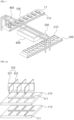
- FIG. 1 is a schematic diagram illustrating an electrolyte extraction system of the present disclosure.
- FIGS. 2a and 2b are schematic diagrams of a blade unit 320 and an upper jig 310.
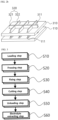
- FIG. 3 is a block diagram illustrating an electrolyte extraction method of the present disclosure.
- the electrolyte extraction system and method of the present disclosure is for extracting electrolyte from a secondary battery 11 which is a finished product, and after destroying the battery case, the electrolyte may be extracted. More specifically, it may extract the electrolyte by immersing the pieces of the battery 11 in an electrolyte extraction solvent, by cutting together an electrode assembly formed by stacking a positive electrode current collector, a negative electrode current collector and a separator, and a battery case accommodating the electrode assembly into a plurality of pieces. In other words, the electrolyte extraction system and method of the present disclosure may extract the electrolyte by cutting the used or unused finished battery 11 into a plurality of pieces.
- the electrolyte extraction system and method of the present disclosure may be used for pretreatment of the battery 11 for an experiment analyzing the absolute amount of the electrolyte remaining before and after the operation of the battery 11 and the depletion tendency according to the operation, through the analysis of the absolute content of the electrolyte remaining in the battery 11.
- the battery 11 to which the electrolyte extraction system and method of the present disclosure is applied is a secondary battery, and may be a pouch-type battery, a prismatic battery, a cylindrical battery, a coin-type battery, and the like, and may be more specialized for a pouch-type battery.
- an electrolyte extraction system of the present disclosure may include:
- the electrolyte extraction system of the present disclosure may be performed for a plurality of the batteries 11. Therefore, in order to sequentially input or discharge the plurality of batteries 11 to the process of the system, it may be preferable that the first transfer unit 100 and the second transfer unit 200 be provided to be capable of linearly moving the lower jig 110 and the electrolyte extraction tank 210.
- the first transfer unit 100 and the second transfer unit 200 may be conveyor belts.
- a plurality of the lower jigs 110 and a plurality of the electrolyte extraction tanks 210 may be provided, the plurality of lower jigs 110 may be arranged along the longitudinal direction of the first transfer unit 100, and the plurality of electrolyte extraction tanks 210 may be arranged along the longitudinal direction of the second transfer unit 200.
- the lower jig 110 is made of a material that does not deform or break at a temperature of minus 190°C or less, and for example, the material of the lower jig 110 is SUS, aluminum or other alloys (iron alloy, nickel alloy, etc.), etc., which may maintain durability in a situation of rapid temperature change due to repeated contact with liquid nitrogen, and a material having cold resistance in an ultra-low temperature environment may be used without limitation.
- the lower jig 110 may be provided in the shape of a plate having a surface perpendicular to the vertical direction.
- the battery 11 is mounted on the upper surface of the lower jig 110, and the adhesive is applied between the lower surface of the battery 11 and the upper surface of the lower jig 110, so that the battery 11 may be fixed on the upper surface of the lower jig 110.
- the adhesive By fixing the battery 11 to the right position on the lower jig 110 with an adhesive, it may prevent the battery 11 from escaping from the right position until the battery 11 is pressed with an upper jig 310 to be described later in the freezing tank 600.
- the battery 11 may be fixed to the right position on the lower jig 110 by providing a separate jig in the lower jig 110 in addition to the adhesive.
- the lower jig 110 When the battery 11 is fixed to the lower jig 110, the lower jig 110 is put into the first transfer unit 100, and after moving to the loading unit 400 through the first transfer unit 100, it may be put into the freezing tank 600 through the loading unit 400.
- the loading unit 400 may be a gantry robot or multi-axis robot equipped with an end effector capable of holding the lower jig 110 such as a gripper, or an actuator capable of pushing or pulling the lower jig 110.
- the freezing tank 600 may be filled with a cooling medium capable of cooling the battery 11 such as liquid nitrogen therein.
- the cooling medium may directly contact the battery 11 to cool the battery 11. It is preferable that the cooling medium filled in the freezing tank 600 does not affect the analysis of the electrolyte, and therefore liquid nitrogen may be the most preferable cooling medium.
- the freezing tank 600 may be a water tank having an open upper side.
- the battery 11 may be accommodated in the freezing tank 600 through the upper part of the freezing tank 600.
- the lower jig 110 and the battery 11 accommodated in the freezing tank 600 may be completely immersed in liquid nitrogen.
- the electrolyte extraction system of the present disclosure cuts the battery 11 in an ultra-low temperature environment, it may prevent accidents such as explosion due to an impact applied to the battery 11, and easily cut the battery 11 into multiple pieces.
- the cutting unit may include an upper jig 310 configured to press an upper surface of the battery 11, a blade unit 320 configured to penetrate the upper jig 310 in a vertical direction, and a driving unit (not shown) configured to drive the upper jig 310 and the blade unit 320 in the vertical direction.
- a lower surface of the upper jig 310 and the upper surface of the lower jig 110 may face each other with the battery 11 interposed therebetween, a blade penetration hole 311 through which the blade unit 320 passes may be formed in the upper jig 310, and a blade protection groove 111 may be formed in the lower jig 110 at a position facing the blade penetration hole 311. Since the electrolyte extraction system of the present disclosure cuts the battery 11 at a very low temperature, the adhesive force between the battery 11 and the lower jig 110 may be weakened. Therefore, it is necessary to fix the battery 11 more completely, and the battery 11 may be completely fixed by pressing the upper surface of the battery 11 with the upper jig 310.
- the battery 11 may be cut by using an imaginary straight line perpendicular to the vertical direction as a cutting line.
- the blade unit 320 cuts the battery 11 while moving in the upward direction, and the battery 11 may be separated into a plurality of pieces in a horizontal direction.
- the blade unit 320 needs to pass through the upper jig 310 in order to access the battery 11.
- the lower surface of the upper jig 310 and the upper surface of the lower jig 110 face each other with the battery 11 interposed therebetween, and a blade penetration hole 311 through which the blade unit 320 passes may be formed in the upper jig 310.
- a blade protection groove 111 may be formed at a position facing the blade penetration hole 311 in the lower jig 110.
- the blade unit 320 may include a first blade 321 extending in a first direction perpendicular to the vertical direction, and a second blade 322 extending in a second direction perpendicular to the vertical direction and the first direction.
- the blade unit 320 may be formed in a cross shape in which the first blade 321 and the second blade 322 intersect.
- the length in the first direction of the first blade 321 is formed longer than the length in the second direction of the second blade 322, and a plurality of second blades 322 may be coupled to one first blade 321.
- the length in the first direction of the first blade 321 may be formed longer than the length in the first direction of the battery 11, and the length of the second blade 322 in the second direction may be longer than the length of the battery 11 in the second direction.
- the blades of the first blade 321 and the second blade 322 may be formed at the lower end, and the driving unit may be connected to the upper end.
- the blade penetration hole 311 formed in the upper jig 310 may be formed to correspond thereto in consideration of the standard, shape and arrangement of the first blade 321 and the second blade 322.
- the blade penetration hole 311 may also be formed in a cross shape.
- the driving unit may bring the upper jig 310 closer to the battery 11, and then bring the blade unit 320 closer to the battery 11.
- the driving unit may be provided as two independent power sources, respectively, provided in the upper jig 310 and the blade unit 320, provided in one power source blade unit 320, and the upper jig 310 and the blade unit 320 may be coupled to each other in a material or structure capable of relative length deformation in the vertical direction.
- the upper jig 310 and the blade unit 320 may be coupled to each other with a guide bar or an elastic material therebetween.
- the power source of the driving unit may be, for example, a pneumatic actuator, an electric linear motor, or the like.
- the upper jig 310 is removed from the upper surface of the battery 11, and the lower jig 110 and the battery 11 may be moved to the electrolyte extraction tank 210 through the unloading unit 500.
- the unloading unit 500 may be a gantry robot or multi-axis robot equipped with an end effector capable of gripping the lower jig 110 such as a gripper, or an actuator capable of pushing or pulling the lower jig 110.
- the electrolyte extraction tank 210 is filled with an electrolyte extraction solvent, and the electrolyte extraction solvent may be an organic solvent such as alcohols, ketones, carbonates, and propionates.
- the electrolyte extraction tank 210 is provided with an open top, and the unloading unit 500 may load the battery 11 and the lower jig 110 through the top of the electrolyte extraction tank into the electrolyte extraction tank 210.
- the plurality of electrolyte extraction tanks 210 are provided and prepared in a state in which they are arranged along the longitudinal direction of the second transfer unit 200, and when the battery 11 is loaded in the empty electrolyte extraction tank 210, the plurality of electrolyte extraction tanks 210 may be moved through the second transfer unit 200, and the empty electrolyte extraction tank 210 may be on standby in front of the unloading unit 500 again.
- the electrolyte extraction method of the present disclosure may include:
- the battery 11 may be adhered to the lower jig 110 with an adhesive.
- a plurality of the batteries 11 and a plurality of the lower jigs 110 are provided, and each of the plurality of batteries 11 is mounted on each of the plurality of lower jigs 110, and the freezing step, the fixing step, the cutting step, and the unloading step may be sequentially performed for each of the plurality of batteries 11.
- the loading step S10 and the freezing step S20 may be performed through the loading unit 400 and the first moving unit 100.
- the fixing step S30 and the cutting step S40 may be performed through a cutting unit.
- the unloading step S50 may be performed through the unloading unit 500.
- a plurality of the electrolyte extraction tank 210 may be provided, and each of the plurality of batteries 11 may be accommodated in the different electrolyte extraction tank 210.
- the electrolyte extraction system of the present disclosure is an automated system, and may be capable of rapid electrolyte extraction for a plurality of batteries.
- the electrolyte extraction system and method of the present disclosure may prevent accidents due to an impact applied to the battery and stably extract the electrolyte inside the battery without loss.
Landscapes
- Chemical & Material Sciences (AREA)
- Chemical Kinetics & Catalysis (AREA)
- Engineering & Computer Science (AREA)
- Electrochemistry (AREA)
- General Chemical & Material Sciences (AREA)
- Manufacturing & Machinery (AREA)
- Life Sciences & Earth Sciences (AREA)
- Analytical Chemistry (AREA)
- Immunology (AREA)
- Health & Medical Sciences (AREA)
- Hydrology & Water Resources (AREA)
- Biochemistry (AREA)
- General Health & Medical Sciences (AREA)
- General Physics & Mathematics (AREA)
- Physics & Mathematics (AREA)
- Pathology (AREA)
- Mechanical Engineering (AREA)
- Sustainable Development (AREA)
- Secondary Cells (AREA)
- Sampling And Sample Adjustment (AREA)
- Filling, Topping-Up Batteries (AREA)
- Fuel Cell (AREA)
Abstract
Description
- This application claims the benefit of priority based on
Korean Patent Application No. 10-2021-0100283 filed on July 30, 2020 - The present disclosure relates to an electrolyte extraction system and method, and more particularly, to an electrolyte extraction system and method for stably extracting electrolyte from a battery by disassembling the battery.
- In battery development, there is a continuous need to understand the relationship between the degree of depletion of electrolyte according to the driving of the battery and the mechanism of battery degradation.
- For example, by analyzing the absolute content of the electrolyte remaining in the battery, it is necessary to understand the absolute amount of the electrolyte before and after driving the battery and the tendency of electrolyte depletion due to the driving.
- To this end, after a battery which is a finished product is driven under specific conditions, the electrolyte inside the battery must be extracted, and for this purpose, the process of disassembling the battery to extract the electrolyte inside the battery case is performed.
- In performing the above process, as an automated method and system, there is a need for a method and system capable of preventing an accident due to an impact applied to the battery and stably extracting the electrolyte inside the battery without loss.
- The present disclosure relates to an electrolyte extraction system and method, and more particularly, an object of the present disclosure is to provide an electrolyte extraction system and method for stably extracting an electrolyte from a battery without loss by disassembling the battery.
- Technical objects achieved by the present disclosure are not limited to the technical objects mentioned above, and other technical objects not mentioned will be clearly understood by one of ordinary skill in the art to which the present disclosure belongs from the following description.
- An electrolyte extraction system of the present disclosure may include:
- a first transfer unit configured to transfer a lower jig having an upper surface on which a battery is mounted;
- a loading unit configured to accommodate the lower jig together with the battery in a freezing tank filled with liquid nitrogen;
- a cutting unit configured to cut the battery inside the freezing tank;
- an unloading unit configured to take out the lower jig together with the battery from the freezing tank and accommodate in an electrolyte extraction tank; and
- a second transfer unit configured to transfer the electrolyte extraction tank in which the battery is accommodated.
- Advantageous Effects
- The electrolyte extraction system of the present idisclosure is an automated system, and may be capable of rapid electrolyte extraction for a plurality of batteries.
- The electrolyte extraction system and method of the present disclosure may prevent accidents due to an impact applied to the battery and stably extract the electrolyte inside the battery without loss.
-
-
FIG. 1 is a schematic diagram illustrating an electrolyte extraction system of the present disclosure. -
FIGS. 2a and2b are schematic diagrams of a blade unit and an upper jig. -
FIG. 3 is a block diagram illustrating an electrolyte extraction method of the present disclosure. - An electrolyte extraction system of the present disclosure may include:
- a first transfer unit configured to transfer a lower jig having an upper surface on which a battery is mounted;
- a loading unit configured to accommodate the lower jig together with the battery in a freezing tank filled with liquid nitrogen;
- a cutting unit configured to cut the battery inside the freezing tank;
- an unloading unit configured to take out the lower jig together with the battery from the freezing tank and accommodate in an electrolyte extraction tank; and
- a second transfer unit configured to transfer the electrolyte extraction tank in which the battery is accommodated.
- In the electrolyte extraction system of the present disclosure, the first transfer unit and the second transfer unit may be conveyor belts.
- In the electrolyte extraction system of the present disclosure, a plurality of the lower jigs and a plurality of the electrolyte extraction tanks may be provided, the plurality of lower jigs may be arranged along a longitudinal direction of the first transfer unit, and the plurality of electrolyte extraction tanks may be arranged along a longitudinal direction of the second transfer unit.
- In the electrolyte extraction system of the present disclosure, the cutting unit may include an upper jig configured to press an upper surface of the battery, a blade unit configured to penetrate the upper jig in a vertical direction, and a driving unit configured to drive the upper jig and the blade unit in the vertical direction.
- In the electrolyte extraction system of the present disclosure, a lower surface of the upper jig and the upper surface of the lower jig may face each other with the battery interposed therebetween, a blade penetration hole through which the blade unit passes may be formed in the upper jig, and a blade protection groove may be formed in the lower jig at a position facing the blade penetration hole.
- In the electrolyte extraction system of the present disclosure, the blade unit may include a first blade extending in a first direction perpendicular to the vertical direction, and a second blade extending in a second direction perpendicular to the vertical direction and the first direction.
- In the electrolyte extraction system of the present disclosure, the electrolyte extraction tank may be filled with an electrolyte extraction solvent, and the electrolyte extraction solvent may be an organic solvent.
- An electrolyte extraction method of the present disclosure may include
- a loading step by mounting a pouch-type battery on an upper surface of a lower jig;
- a freezing step by immersing the lower jig on which the battery is mounted in liquid nitrogen filled in a freezing tank;
- a fixing step by fixing the battery by pressing an upper surface of the battery with an upper jig;
- a cutting step by cutting the battery by passing a blade through a blade penetration hole formed in the upper jig;
- an unloading step by separating the upper jig from the battery and taking the battery and the lower jig out of the freezing tank; and
- an electrolyte extracting step by immersing the battery and the lower jig in an electrolyte extraction solvent filled in an electrolyte extraction tank.
- In the loading step by the electrolyte extraction method of the present disclosure, a plurality of the batteries and a plurality of the lower jigs may be provided, each of the plurality of batteries may be mounted on each of the plurality of lower jigs, and the freezing step, the fixing step, the cutting step, and the unloading step may be sequentially performed for each of the plurality of batteries.
- In the extracting step by the electrolyte extraction method of the present disclosure, a plurality of the electrolyte extraction tanks may be provided, and each of the the plurality of batteries may be accommodated in a different electrolyte extraction tank.
- Hereinafter, embodiments according to the present disclosure will be described in detail with reference to the accompanying drawings. In this process, the size or shape of the components shown in the drawings may be exaggerated for clarity and convenience of explanation. In addition, terms specifically defined in consideration of the configuration and operation of the present disclosure may vary depending on the intention or custom of the user or operator. Definitions of these terms should be made based on the content throughout this specification.
- In the description of the present invention, it should be noted that the orientation or positional relationship indicated by the terms "center", "top", "bottom" "left", "right", "vertical", "horizontal", "inside", "outside", "one side", "other side", etc., are based on the orientation or positional relationship shown in the drawings, or the orientation or positional relationship usually placed when using the product of the present disclosure, and it is not to be construed as limiting the present disclosure as it is only for the purpose of description of the present description and does not suggest or imply that the indicated device or element must have the specified orientation and be configured or operated in the specified orientation.
-
FIG. 1 is a schematic diagram illustrating an electrolyte extraction system of the present disclosure.FIGS. 2a and2b are schematic diagrams of ablade unit 320 and anupper jig 310.FIG. 3 is a block diagram illustrating an electrolyte extraction method of the present disclosure. - Hereinafter, with reference to
FIGS. 1 to 3 , the electrolyte extraction system and method of the present disclosure will be described in detail. - The electrolyte extraction system and method of the present disclosure is for extracting electrolyte from a secondary battery 11 which is a finished product, and after destroying the battery case, the electrolyte may be extracted. More specifically, it may extract the electrolyte by immersing the pieces of the battery 11 in an electrolyte extraction solvent, by cutting together an electrode assembly formed by stacking a positive electrode current collector, a negative electrode current collector and a separator, and a battery case accommodating the electrode assembly into a plurality of pieces. In other words, the electrolyte extraction system and method of the present disclosure may extract the electrolyte by cutting the used or unused finished battery 11 into a plurality of pieces.
- The electrolyte extraction system and method of the present disclosure may be used for pretreatment of the battery 11 for an experiment analyzing the absolute amount of the electrolyte remaining before and after the operation of the battery 11 and the depletion tendency according to the operation, through the analysis of the absolute content of the electrolyte remaining in the battery 11.
- The battery 11 to which the electrolyte extraction system and method of the present disclosure is applied is a secondary battery, and may be a pouch-type battery, a prismatic battery, a cylindrical battery, a coin-type battery, and the like, and may be more specialized for a pouch-type battery.
- As illustrated in
FIG.1 , an electrolyte extraction system of the present disclosure may include: - a
first transfer unit 100 configured to transfer alower jig 110 having an upper surface on which a battery 11 is mounted; - a
loading unit 400 configured to accommodate thelower jig 110 together with the battery 11 in a freezingtank 600 filled with liquid nitrogen; - a cutting unit (not shown) configured to cut the battery 11 inside the freezing
tank 600; - an
unloading unit 500 configured to take out thelower jig 110 together with the battery 11 from the freezingtank 600 and accommodate in anelectrolyte extraction tank 210; and - a
second transfer unit 200 configured to transfer theelectrolyte extraction tank 210 in which the battery 11 is accommodated. - The electrolyte extraction system of the present disclosure may be performed for a plurality of the batteries 11. Therefore, in order to sequentially input or discharge the plurality of batteries 11 to the process of the system, it may be preferable that the
first transfer unit 100 and thesecond transfer unit 200 be provided to be capable of linearly moving thelower jig 110 and theelectrolyte extraction tank 210. For example, thefirst transfer unit 100 and thesecond transfer unit 200 may be conveyor belts. - A plurality of the
lower jigs 110 and a plurality of theelectrolyte extraction tanks 210 may be provided, the plurality oflower jigs 110 may be arranged along the longitudinal direction of thefirst transfer unit 100, and the plurality ofelectrolyte extraction tanks 210 may be arranged along the longitudinal direction of thesecond transfer unit 200. - The
lower jig 110 is made of a material that does not deform or break at a temperature of minus 190°C or less, and for example, the material of thelower jig 110 is SUS, aluminum or other alloys (iron alloy, nickel alloy, etc.), etc., which may maintain durability in a situation of rapid temperature change due to repeated contact with liquid nitrogen, and a material having cold resistance in an ultra-low temperature environment may be used without limitation. Thelower jig 110 may be provided in the shape of a plate having a surface perpendicular to the vertical direction. The battery 11 is mounted on the upper surface of thelower jig 110, and the adhesive is applied between the lower surface of the battery 11 and the upper surface of thelower jig 110, so that the battery 11 may be fixed on the upper surface of thelower jig 110. By fixing the battery 11 to the right position on thelower jig 110 with an adhesive, it may prevent the battery 11 from escaping from the right position until the battery 11 is pressed with anupper jig 310 to be described later in the freezingtank 600. The battery 11 may be fixed to the right position on thelower jig 110 by providing a separate jig in thelower jig 110 in addition to the adhesive. - When the battery 11 is fixed to the
lower jig 110, thelower jig 110 is put into thefirst transfer unit 100, and after moving to theloading unit 400 through thefirst transfer unit 100, it may be put into the freezingtank 600 through theloading unit 400. - The
loading unit 400 may be a gantry robot or multi-axis robot equipped with an end effector capable of holding thelower jig 110 such as a gripper, or an actuator capable of pushing or pulling thelower jig 110. - The freezing
tank 600 may be filled with a cooling medium capable of cooling the battery 11 such as liquid nitrogen therein. The cooling medium may directly contact the battery 11 to cool the battery 11. It is preferable that the cooling medium filled in the freezingtank 600 does not affect the analysis of the electrolyte, and therefore liquid nitrogen may be the most preferable cooling medium. - The freezing
tank 600 may be a water tank having an open upper side. The battery 11 may be accommodated in the freezingtank 600 through the upper part of the freezingtank 600. Thelower jig 110 and the battery 11 accommodated in the freezingtank 600 may be completely immersed in liquid nitrogen. - Since the electrolyte extraction system of the present disclosure cuts the battery 11 in an ultra-low temperature environment, it may prevent accidents such as explosion due to an impact applied to the battery 11, and easily cut the battery 11 into multiple pieces.
- As illustrated in
FIGS 2a and2b , the cutting unit may include anupper jig 310 configured to press an upper surface of the battery 11, ablade unit 320 configured to penetrate theupper jig 310 in a vertical direction, and a driving unit (not shown) configured to drive theupper jig 310 and theblade unit 320 in the vertical direction. - A lower surface of the
upper jig 310 and the upper surface of thelower jig 110 may face each other with the battery 11 interposed therebetween, ablade penetration hole 311 through which theblade unit 320 passes may be formed in theupper jig 310, and ablade protection groove 111 may be formed in thelower jig 110 at a position facing theblade penetration hole 311. Since the electrolyte extraction system of the present disclosure cuts the battery 11 at a very low temperature, the adhesive force between the battery 11 and thelower jig 110 may be weakened. Therefore, it is necessary to fix the battery 11 more completely, and the battery 11 may be completely fixed by pressing the upper surface of the battery 11 with theupper jig 310. - In the electrolyte extraction system of the present disclosure, the battery 11 may be cut by using an imaginary straight line perpendicular to the vertical direction as a cutting line. In other words, the
blade unit 320 cuts the battery 11 while moving in the upward direction, and the battery 11 may be separated into a plurality of pieces in a horizontal direction. - Therefore, as illustrated in
FIG. 2b , in the state where the battery 11 is sandwiched between theupper jig 310 and thelower jig 110, theblade unit 320 needs to pass through theupper jig 310 in order to access the battery 11. In other words, the lower surface of theupper jig 310 and the upper surface of thelower jig 110 face each other with the battery 11 interposed therebetween, and ablade penetration hole 311 through which theblade unit 320 passes may be formed in theupper jig 310. As illustrated inFIG 2a , in order for the blade of theblade unit 320 to completely pass through the battery 11, ablade protection groove 111 may be formed at a position facing theblade penetration hole 311 in thelower jig 110. - The
blade unit 320 may include afirst blade 321 extending in a first direction perpendicular to the vertical direction, and asecond blade 322 extending in a second direction perpendicular to the vertical direction and the first direction. In other words, theblade unit 320 may be formed in a cross shape in which thefirst blade 321 and thesecond blade 322 intersect. The length in the first direction of thefirst blade 321 is formed longer than the length in the second direction of thesecond blade 322, and a plurality ofsecond blades 322 may be coupled to onefirst blade 321. - The length in the first direction of the
first blade 321 may be formed longer than the length in the first direction of the battery 11, and the length of thesecond blade 322 in the second direction may be longer than the length of the battery 11 in the second direction. - The blades of the
first blade 321 and thesecond blade 322 may be formed at the lower end, and the driving unit may be connected to the upper end. - The
blade penetration hole 311 formed in theupper jig 310 may be formed to correspond thereto in consideration of the standard, shape and arrangement of thefirst blade 321 and thesecond blade 322. For example, when thefirst blade 321 and thesecond blade 322 are formed in a cross shape, theblade penetration hole 311 may also be formed in a cross shape. - When cutting the battery 11, after pressing the upper surface of the battery 11 with the
upper jig 310, the battery 11 may be cut through theblade unit 320. In other words, the driving unit may bring theupper jig 310 closer to the battery 11, and then bring theblade unit 320 closer to the battery 11. The driving unit may be provided as two independent power sources, respectively, provided in theupper jig 310 and theblade unit 320, provided in one powersource blade unit 320, and theupper jig 310 and theblade unit 320 may be coupled to each other in a material or structure capable of relative length deformation in the vertical direction. For example, theupper jig 310 and theblade unit 320 may be coupled to each other with a guide bar or an elastic material therebetween. - The power source of the driving unit may be, for example, a pneumatic actuator, an electric linear motor, or the like.
- When the battery 11 is cut, the
upper jig 310 is removed from the upper surface of the battery 11, and thelower jig 110 and the battery 11 may be moved to theelectrolyte extraction tank 210 through theunloading unit 500. - The
unloading unit 500 may be a gantry robot or multi-axis robot equipped with an end effector capable of gripping thelower jig 110 such as a gripper, or an actuator capable of pushing or pulling thelower jig 110. - The
electrolyte extraction tank 210 is filled with an electrolyte extraction solvent, and the electrolyte extraction solvent may be an organic solvent such as alcohols, ketones, carbonates, and propionates. - The
electrolyte extraction tank 210 is provided with an open top, and theunloading unit 500 may load the battery 11 and thelower jig 110 through the top of the electrolyte extraction tank into theelectrolyte extraction tank 210. - The plurality of
electrolyte extraction tanks 210 are provided and prepared in a state in which they are arranged along the longitudinal direction of thesecond transfer unit 200, and when the battery 11 is loaded in the emptyelectrolyte extraction tank 210, the plurality ofelectrolyte extraction tanks 210 may be moved through thesecond transfer unit 200, and the emptyelectrolyte extraction tank 210 may be on standby in front of theunloading unit 500 again. - As illustrated in
FIG. 3 , the electrolyte extraction method of the present disclosure may include: - a loading step S10 of mounting the pouch-type battery 11 on an upper surface of the
lower jig 110; - a freezing step S20 of immersing the
lower jig 110 on which the battery 11 is mounted in liquid nitrogen filled in the freezingtank 600; - a fixing step S30 of fixing the battery 11 by pressing an upper surface of the battery 11 with the
upper jig 310; - a cutting step S40 of cutting the battery 11 by passing a blade of the
blade unit 320 through theblade penetration hole 311 formed in theupper jig 310; - an unloading step S50 of separating the
upper jig 310 from the battery 11 and taking the battery 11 and thelower jig 110 out of the freezingtank 600; and - an electrolyte extracting step S60 of immersing the battery 11 and the
lower jig 110 in an electrolyte extraction solvent filled in theelectrolyte extraction tank 210. - In the loading step S10, the battery 11 may be adhered to the
lower jig 110 with an adhesive. - In the loading step S10, a plurality of the batteries 11 and a plurality of the
lower jigs 110 are provided, and each of the plurality of batteries 11 is mounted on each of the plurality oflower jigs 110, and the freezing step, the fixing step, the cutting step, and the unloading step may be sequentially performed for each of the plurality of batteries 11. - The loading step S10 and the freezing step S20 may be performed through the
loading unit 400 and the first movingunit 100. - The fixing step S30 and the cutting step S40 may be performed through a cutting unit.
- The unloading step S50 may be performed through the
unloading unit 500. - In the extracting step S60, a plurality of the
electrolyte extraction tank 210 may be provided, and each of the plurality of batteries 11 may be accommodated in the differentelectrolyte extraction tank 210. - Although the embodiments according to the present disclosure have been described above, these are merely exemplary, and one of ordinary skill in the art will understand that various modifications and equivalent ranges of embodiments are possible therefrom. Accordingly, the true technical protection scope of the present disclosure should be defined by the following claims.
-
- 11...
Battery 100...First transfer unit - 110...
Lower jig 111...Blade protection groove - 200...
Second transfer unit 210...Electrolyte extraction tank - 310...
Upper jig 311 ... Blade penetration hole - 320...
Blade unit 321...First blade - 322...
Second blade 400...Loading unit - 500...Unloading
unit 600...Freezing tank - The electrolyte extraction system of the present disclosure is an automated system, and may be capable of rapid electrolyte extraction for a plurality of batteries.
- The electrolyte extraction system and method of the present disclosure may prevent accidents due to an impact applied to the battery and stably extract the electrolyte inside the battery without loss.
Claims (10)
- An electrolyte extraction system comprising:a first transfer unit configured to transfer a lower jig having an upper surface on which a battery is mounted;a loading unit configured to accommodate the lower jig together with the battery in a freezing tank filled with liquid nitrogen;a cutting unit configured to cut the battery inside the freezing tank;an unloading unit configured to take out the lower jig together with the battery from the freezing tank and accommodate in an electrolyte extraction tank; anda second transfer unit configured to transfer the electrolyte extraction tank in which the battery is accommodated.
- The electrolyte extraction system according to claim 1, wherein the first transfer unit and the second transfer unit are conveyor belts.
- The electrolyte extraction system according to claim 2, wherein a plurality of the lower jigs and a plurality of the electrolyte extraction tanks are provided,the plurality of lower jigs are arranged along a longitudinal direction of the first transfer unit, andthe plurality of electrolyte extraction tanks are arranged along a longitudinal direction of the second transfer unit.
- The electrolyte extraction system according to claim 1, wherein the cutting unit comprises:an upper jig configured to press an upper surface of the battery;a blade unit configured to penetrate the upper jig in a vertical direction; anda driving unit configured to drive the upper jig and the blade unit in the vertical direction.
- The electrolyte extraction system according to claim 4, wherein a lower surface of the upper jig and the upper surface of the lower jig face each other with the battery interposed therebetween,a blade penetration hole through which the blade unit passes is formed in the upper jig, anda blade protection groove is formed in the lower jig at a position facing the blade penetration hole.
- The electrolyte extraction system according to claim 4, wherein the blade unit comprises:a first blade extending in a first direction perpendicular to the vertical direction; anda second blade extending in a second direction perpendicular to the vertical direction and the first direction.
- The electrolyte extraction system according to claim 1, wherein the electrolyte extraction tank is filled with an electrolyte extraction solvent, and
the electrolyte extraction solvent is an organic solvent. - An electrolyte extraction method comprising:a loading step by mounting a pouch-type battery on an upper surface of a lower jig;a freezing step by immersing the lower jig on which the battery is mounted in liquid nitrogen filled in a freezing tank;a fixing step by fixing the battery by pressing an upper surface of the battery with an upper jig;a cutting step by cutting the battery by passing a blade through a blade penetration hole formed in the upper jig;an unloading step by separating the upper jig from the battery and taking the battery and the lower jig out of the freezing tank; andan electrolyte extracting step by immersing the battery and the lower jig in an electrolyte extraction solvent filled in an electrolyte extraction tank.
- The electrolyte extraction method according to claim 8, wherein in the loading step,a plurality of the batteries and a plurality of the lower jigs are provided,each of the plurality of batteries is mounted on each of the plurality of lower jigs, andthe freezing step, the fixing step, the cutting step, and the unloading step are sequentially performed for each of the plurality of batteries.
- The electrolyte extraction method according to claim 8, wherein in the extracting step,
a plurality of the electrolyte extraction tanks are provided, and each of a plurality of the batteries is accommodated in a different electrolyte extraction tank.
Applications Claiming Priority (2)
| Application Number | Priority Date | Filing Date | Title |
|---|---|---|---|
| KR1020210100283A KR102798074B1 (en) | 2021-07-30 | 2021-07-30 | System and method for extracting electrolyte |
| PCT/KR2022/010952 WO2023008873A1 (en) | 2021-07-30 | 2022-07-26 | Electrolyte extraction system and method |
Publications (3)
| Publication Number | Publication Date |
|---|---|
| EP4246661A1 true EP4246661A1 (en) | 2023-09-20 |
| EP4246661A4 EP4246661A4 (en) | 2025-06-11 |
| EP4246661B1 EP4246661B1 (en) | 2025-10-22 |
Family
ID=85087076
Family Applications (1)
| Application Number | Title | Priority Date | Filing Date |
|---|---|---|---|
| EP22849849.9A Active EP4246661B1 (en) | 2021-07-30 | 2022-07-26 | Electrolyte extraction system and method |
Country Status (8)
| Country | Link |
|---|---|
| US (1) | US12438211B2 (en) |
| EP (1) | EP4246661B1 (en) |
| JP (1) | JP7551220B2 (en) |
| KR (1) | KR102798074B1 (en) |
| CN (1) | CN116762208A (en) |
| ES (1) | ES3059699T3 (en) |
| PL (1) | PL4246661T3 (en) |
| WO (1) | WO2023008873A1 (en) |
Families Citing this family (1)
| Publication number | Priority date | Publication date | Assignee | Title |
|---|---|---|---|---|
| WO2026023890A1 (en) * | 2024-07-25 | 2026-01-29 | 주식회사 엘지에너지솔루션 | Jig for extracting electrolyte |
Family Cites Families (26)
| Publication number | Priority date | Publication date | Assignee | Title |
|---|---|---|---|---|
| US3680420A (en) * | 1970-10-22 | 1972-08-01 | Sorvall Inc Ivan | Cryogenic microtome apparatus |
| JP2721467B2 (en) | 1993-02-25 | 1998-03-04 | キヤノン株式会社 | Lithium battery material recovery method |
| JPH09211090A (en) | 1996-01-30 | 1997-08-15 | Yuasa Corp | Method for measuring remaining capacity of lead storage battery |
| CA2199096C (en) * | 1996-03-05 | 2001-01-23 | Soichiro Kawakami | Process and apparatus for recovering components of sealed type battery |
| JP2000235873A (en) * | 1996-03-05 | 2000-08-29 | Canon Inc | Recycling method for used sealed battery members |
| JP3137286B2 (en) | 1996-03-05 | 2001-02-19 | キヤノン株式会社 | Method and apparatus for collecting sealed battery member |
| JP3935594B2 (en) * | 1997-03-14 | 2007-06-27 | 三菱重工業株式会社 | Nonaqueous solvent battery processing method |
| JPH1197065A (en) * | 1997-04-23 | 1999-04-09 | Hydro Quebec | Ultra thin layer solid lithium battery and manufacture of the same |
| JP3080606B2 (en) | 1998-03-11 | 2000-08-28 | アサカ理研工業株式会社 | Device for deactivating non-aqueous electrolyte batteries |
| KR100271320B1 (en) * | 1998-05-29 | 2000-11-01 | 권호택 | Extraction method of electrolyte impregnated with electrolyte |
| KR20000019850A (en) | 1998-09-16 | 2000-04-15 | 박종덕 | Method for recycling exhausted lithium secondary battery |
| KR100509591B1 (en) * | 1999-02-19 | 2005-08-23 | 삼성에스디아이 주식회사 | Dismemberment device used in secondary battery and mothed for dismembering the same |
| JP2005055175A (en) | 1999-09-07 | 2005-03-03 | National Agriculture & Bio-Oriented Research Organization | Sample preparation method and apparatus |
| JP4703989B2 (en) * | 2004-08-31 | 2011-06-15 | 野村興産株式会社 | Disassembly method of NAS battery |
| KR101077280B1 (en) * | 2009-10-29 | 2011-10-27 | 허욱환 | Recycling apparatus and method of the waste lithium battery |
| JP5488425B2 (en) | 2010-11-25 | 2014-05-14 | 住友金属鉱山株式会社 | Battery crushing apparatus and crushing method |
| KR101372010B1 (en) | 2012-10-12 | 2014-03-07 | 현대자동차주식회사 | A method for analyzing the components in an electrolytic solution of lithium-ion battery |
| US20140298962A1 (en) * | 2013-04-03 | 2014-10-09 | GM Global Technology Operations LLC | Elastic averaging alignment system, method of making the same and cutting punch therefor |
| JP2015002107A (en) * | 2013-06-17 | 2015-01-05 | Jointエンジニアリング株式会社 | Method for extracting electrolytic solution from organic electrolytic battery |
| KR102111908B1 (en) * | 2013-11-08 | 2020-05-18 | 현대모비스 주식회사 | Extracting method for secondary battery electrolyte |
| JP2020029575A (en) * | 2016-12-27 | 2020-02-27 | 日立金属株式会社 | Method and apparatus for collecting molten salt electrolyte |
| AU2018276326B2 (en) | 2017-05-30 | 2021-07-15 | 1001297676 Ontario Inc. | A process, apparatus, and system for recovering materials from batteries |
| KR102362162B1 (en) | 2018-02-13 | 2022-02-10 | 주식회사 엘지에너지솔루션 | Method of quantitative analysis for electrolytic solution of lithium ion battery |
| JP2020113493A (en) * | 2019-01-16 | 2020-07-27 | レーザーテック株式会社 | Lithium-ion battery making method and all-solid-state battery making method |
| KR102332142B1 (en) | 2020-02-06 | 2021-11-30 | (주)켄텍 | Beta-ray type chimney fine dust measuring device with diffusion pipe |
| CN112453021A (en) * | 2020-11-02 | 2021-03-09 | 瓮梅 | Environment-friendly is used for innocent treatment device of waste battery |
-
2021
- 2021-07-30 KR KR1020210100283A patent/KR102798074B1/en active Active
-
2022
- 2022-07-26 CN CN202280011727.2A patent/CN116762208A/en active Pending
- 2022-07-26 US US18/282,981 patent/US12438211B2/en active Active
- 2022-07-26 PL PL22849849.9T patent/PL4246661T3/en unknown
- 2022-07-26 WO PCT/KR2022/010952 patent/WO2023008873A1/en not_active Ceased
- 2022-07-26 EP EP22849849.9A patent/EP4246661B1/en active Active
- 2022-07-26 ES ES22849849T patent/ES3059699T3/en active Active
- 2022-07-26 JP JP2023540602A patent/JP7551220B2/en active Active
Also Published As
| Publication number | Publication date |
|---|---|
| WO2023008873A1 (en) | 2023-02-02 |
| US12438211B2 (en) | 2025-10-07 |
| ES3059699T3 (en) | 2026-03-23 |
| JP2024502826A (en) | 2024-01-23 |
| CN116762208A (en) | 2023-09-15 |
| EP4246661A4 (en) | 2025-06-11 |
| JP7551220B2 (en) | 2024-09-17 |
| KR20230018563A (en) | 2023-02-07 |
| US20240170750A1 (en) | 2024-05-23 |
| PL4246661T3 (en) | 2026-01-26 |
| KR102798074B1 (en) | 2025-04-21 |
| EP4246661B1 (en) | 2025-10-22 |
Similar Documents
| Publication | Publication Date | Title |
|---|---|---|
| US10873065B2 (en) | Battery cell degassing apparatus | |
| KR102519579B1 (en) | Electrode collecting system for spent lithium ion battery | |
| KR102092269B1 (en) | Battery cell degassing apparatus | |
| JP5459825B2 (en) | Storage battery cutting method | |
| US11335944B2 (en) | Secondary battery charging/discharging device | |
| JP5700520B2 (en) | Disassembly method of storage battery | |
| US20180166752A1 (en) | Method and apparatus for disassembling and separating components of batteries | |
| EP4246661B1 (en) | Electrolyte extraction system and method | |
| JP2018049803A (en) | Mounting method of battery stack | |
| KR20220119150A (en) | Battery modules, battery packs, devices and methods of handling faults | |
| CN117983899A (en) | A cutting device, disassembly and recycling equipment and cutting method | |
| EP4287345A1 (en) | Pressure activation device provided with short-circuiting inspection part for battery cell | |
| KR102780030B1 (en) | Disassembling Method of Battery Module Case | |
| EP4166268B1 (en) | Welding apparatus for manufacturing secondary battery, and welding method using same | |
| EP4570718B1 (en) | Quick-change platform, battery production line, and control method | |
| CN218788409U (en) | Electricity core recovery unit that shells | |
| US20240399603A1 (en) | Method and system for energy cell disassembly | |
| KR20230018564A (en) | Apparatus for cutting battery | |
| KR20190119500A (en) | Apparatus for collecting inner gas in secondary electric cell and method thereof | |
| KR102935546B1 (en) | Pressurization activation device in which the degassing process is carried out | |
| CN219998313U (en) | Battery cell shell breaking device and lithium battery recycling equipment | |
| KR100749477B1 (en) | Jig for cap plate welding of secondary battery | |
| US20220123440A1 (en) | Battery module, battery group, power consumption device, and failure handling method | |
| CN218656765U (en) | Cast welding device for processing battery material test piece | |
| JP4461132B2 (en) | Separating jig for engaging body, separating device, and separating method for engaging body |
Legal Events
| Date | Code | Title | Description |
|---|---|---|---|
| STAA | Information on the status of an ep patent application or granted ep patent |
Free format text: STATUS: THE INTERNATIONAL PUBLICATION HAS BEEN MADE |
|
| PUAI | Public reference made under article 153(3) epc to a published international application that has entered the european phase |
Free format text: ORIGINAL CODE: 0009012 |
|
| STAA | Information on the status of an ep patent application or granted ep patent |
Free format text: STATUS: REQUEST FOR EXAMINATION WAS MADE |
|
| 17P | Request for examination filed |
Effective date: 20230612 |
|
| AK | Designated contracting states |
Kind code of ref document: A1 Designated state(s): AL AT BE BG CH CY CZ DE DK EE ES FI FR GB GR HR HU IE IS IT LI LT LU LV MC MK MT NL NO PL PT RO RS SE SI SK SM TR |
|
| DAV | Request for validation of the european patent (deleted) | ||
| DAX | Request for extension of the european patent (deleted) | ||
| A4 | Supplementary search report drawn up and despatched |
Effective date: 20250509 |
|
| RIC1 | Information provided on ipc code assigned before grant |
Ipc: H01M 6/52 20060101ALI20250502BHEP Ipc: H01M 50/691 20210101ALI20250502BHEP Ipc: G01N 1/10 20060101ALI20250502BHEP Ipc: H01M 10/54 20060101AFI20250502BHEP |
|
| GRAP | Despatch of communication of intention to grant a patent |
Free format text: ORIGINAL CODE: EPIDOSNIGR1 |
|
| STAA | Information on the status of an ep patent application or granted ep patent |
Free format text: STATUS: GRANT OF PATENT IS INTENDED |
|
| INTG | Intention to grant announced |
Effective date: 20250725 |
|
| GRAS | Grant fee paid |
Free format text: ORIGINAL CODE: EPIDOSNIGR3 |
|
| GRAA | (expected) grant |
Free format text: ORIGINAL CODE: 0009210 |
|
| STAA | Information on the status of an ep patent application or granted ep patent |
Free format text: STATUS: THE PATENT HAS BEEN GRANTED |
|
| AK | Designated contracting states |
Kind code of ref document: B1 Designated state(s): AL AT BE BG CH CY CZ DE DK EE ES FI FR GB GR HR HU IE IS IT LI LT LU LV MC MK MT NL NO PL PT RO RS SE SI SK SM TR |
|
| REG | Reference to a national code |
Ref country code: CH Ref legal event code: F10 Free format text: ST27 STATUS EVENT CODE: U-0-0-F10-F00 (AS PROVIDED BY THE NATIONAL OFFICE) Effective date: 20251022 Ref country code: GB Ref legal event code: FG4D |
|
| REG | Reference to a national code |
Ref country code: DE Ref legal event code: R096 Ref document number: 602022023659 Country of ref document: DE |
|
| P01 | Opt-out of the competence of the unified patent court (upc) registered |
Free format text: CASE NUMBER: UPC_APP_9186_4246661/2025 Effective date: 20251007 |
|
| REG | Reference to a national code |
Ref country code: IE Ref legal event code: FG4D |
|
| REG | Reference to a national code |
Ref country code: SE Ref legal event code: TRGR |
|
| REG | Reference to a national code |
Ref country code: NL Ref legal event code: MP Effective date: 20251022 |
|
| PG25 | Lapsed in a contracting state [announced via postgrant information from national office to epo] |
Ref country code: NL Free format text: LAPSE BECAUSE OF FAILURE TO SUBMIT A TRANSLATION OF THE DESCRIPTION OR TO PAY THE FEE WITHIN THE PRESCRIBED TIME-LIMIT Effective date: 20251022 |
|
| REG | Reference to a national code |
Ref country code: ES Ref legal event code: FG2A Ref document number: 3059699 Country of ref document: ES Kind code of ref document: T3 Effective date: 20260323 |
|
| REG | Reference to a national code |
Ref country code: LT Ref legal event code: MG9D |
|
| PG25 | Lapsed in a contracting state [announced via postgrant information from national office to epo] |
Ref country code: NO Free format text: LAPSE BECAUSE OF FAILURE TO SUBMIT A TRANSLATION OF THE DESCRIPTION OR TO PAY THE FEE WITHIN THE PRESCRIBED TIME-LIMIT Effective date: 20260122 |
|
| PG25 | Lapsed in a contracting state [announced via postgrant information from national office to epo] |
Ref country code: HR Free format text: LAPSE BECAUSE OF FAILURE TO SUBMIT A TRANSLATION OF THE DESCRIPTION OR TO PAY THE FEE WITHIN THE PRESCRIBED TIME-LIMIT Effective date: 20251022 Ref country code: AT Free format text: LAPSE BECAUSE OF FAILURE TO SUBMIT A TRANSLATION OF THE DESCRIPTION OR TO PAY THE FEE WITHIN THE PRESCRIBED TIME-LIMIT Effective date: 20251022 Ref country code: FI Free format text: LAPSE BECAUSE OF FAILURE TO SUBMIT A TRANSLATION OF THE DESCRIPTION OR TO PAY THE FEE WITHIN THE PRESCRIBED TIME-LIMIT Effective date: 20251022 |
|
| REG | Reference to a national code |
Ref country code: AT Ref legal event code: MK05 Ref document number: 1850024 Country of ref document: AT Kind code of ref document: T Effective date: 20251022 |
|
| PG25 | Lapsed in a contracting state [announced via postgrant information from national office to epo] |
Ref country code: RS Free format text: LAPSE BECAUSE OF FAILURE TO SUBMIT A TRANSLATION OF THE DESCRIPTION OR TO PAY THE FEE WITHIN THE PRESCRIBED TIME-LIMIT Effective date: 20260122 |
|
| PG25 | Lapsed in a contracting state [announced via postgrant information from national office to epo] |
Ref country code: IS Free format text: LAPSE BECAUSE OF FAILURE TO SUBMIT A TRANSLATION OF THE DESCRIPTION OR TO PAY THE FEE WITHIN THE PRESCRIBED TIME-LIMIT Effective date: 20260222 |
|
| PG25 | Lapsed in a contracting state [announced via postgrant information from national office to epo] |
Ref country code: PT Free format text: LAPSE BECAUSE OF FAILURE TO SUBMIT A TRANSLATION OF THE DESCRIPTION OR TO PAY THE FEE WITHIN THE PRESCRIBED TIME-LIMIT Effective date: 20260223 |
|
| PG25 | Lapsed in a contracting state [announced via postgrant information from national office to epo] |
Ref country code: LV Free format text: LAPSE BECAUSE OF FAILURE TO SUBMIT A TRANSLATION OF THE DESCRIPTION OR TO PAY THE FEE WITHIN THE PRESCRIBED TIME-LIMIT Effective date: 20251022 |
|
| PG25 | Lapsed in a contracting state [announced via postgrant information from national office to epo] |
Ref country code: BG Free format text: LAPSE BECAUSE OF FAILURE TO SUBMIT A TRANSLATION OF THE DESCRIPTION OR TO PAY THE FEE WITHIN THE PRESCRIBED TIME-LIMIT Effective date: 20251022 |