EP4246632A1 - A heat management system for a fuel cell vehicle - Google Patents
A heat management system for a fuel cell vehicle Download PDFInfo
- Publication number
- EP4246632A1 EP4246632A1 EP22161874.7A EP22161874A EP4246632A1 EP 4246632 A1 EP4246632 A1 EP 4246632A1 EP 22161874 A EP22161874 A EP 22161874A EP 4246632 A1 EP4246632 A1 EP 4246632A1
- Authority
- EP
- European Patent Office
- Prior art keywords
- electric power
- fuel cell
- heat management
- compressor
- management system
- Prior art date
- Legal status (The legal status is an assumption and is not a legal conclusion. Google has not performed a legal analysis and makes no representation as to the accuracy of the status listed.)
- Pending
Links
Images


Classifications
-
- H—ELECTRICITY
- H01—ELECTRIC ELEMENTS
- H01M—PROCESSES OR MEANS, e.g. BATTERIES, FOR THE DIRECT CONVERSION OF CHEMICAL ENERGY INTO ELECTRICAL ENERGY
- H01M8/00—Fuel cells; Manufacture thereof
- H01M8/04—Auxiliary arrangements, e.g. for control of pressure or for circulation of fluids
- H01M8/04082—Arrangements for control of reactant parameters, e.g. pressure or concentration
- H01M8/04089—Arrangements for control of reactant parameters, e.g. pressure or concentration of gaseous reactants
- H01M8/04119—Arrangements for control of reactant parameters, e.g. pressure or concentration of gaseous reactants with simultaneous supply or evacuation of electrolyte; Humidifying or dehumidifying
- H01M8/04156—Arrangements for control of reactant parameters, e.g. pressure or concentration of gaseous reactants with simultaneous supply or evacuation of electrolyte; Humidifying or dehumidifying with product water removal
-
- B—PERFORMING OPERATIONS; TRANSPORTING
- B60—VEHICLES IN GENERAL
- B60L—PROPULSION OF ELECTRICALLY-PROPELLED VEHICLES; SUPPLYING ELECTRIC POWER FOR AUXILIARY EQUIPMENT OF ELECTRICALLY-PROPELLED VEHICLES; ELECTRODYNAMIC BRAKE SYSTEMS FOR VEHICLES IN GENERAL; MAGNETIC SUSPENSION OR LEVITATION FOR VEHICLES; MONITORING OPERATING VARIABLES OF ELECTRICALLY-PROPELLED VEHICLES; ELECTRIC SAFETY DEVICES FOR ELECTRICALLY-PROPELLED VEHICLES
- B60L58/00—Methods or circuit arrangements for monitoring or controlling batteries or fuel cells, specially adapted for electric vehicles
- B60L58/30—Methods or circuit arrangements for monitoring or controlling batteries or fuel cells, specially adapted for electric vehicles for monitoring or controlling fuel cells
- B60L58/32—Methods or circuit arrangements for monitoring or controlling batteries or fuel cells, specially adapted for electric vehicles for monitoring or controlling fuel cells for controlling the temperature of fuel cells, e.g. by controlling the electric load
- B60L58/34—Methods or circuit arrangements for monitoring or controlling batteries or fuel cells, specially adapted for electric vehicles for monitoring or controlling fuel cells for controlling the temperature of fuel cells, e.g. by controlling the electric load by heating
-
- B—PERFORMING OPERATIONS; TRANSPORTING
- B60—VEHICLES IN GENERAL
- B60L—PROPULSION OF ELECTRICALLY-PROPELLED VEHICLES; SUPPLYING ELECTRIC POWER FOR AUXILIARY EQUIPMENT OF ELECTRICALLY-PROPELLED VEHICLES; ELECTRODYNAMIC BRAKE SYSTEMS FOR VEHICLES IN GENERAL; MAGNETIC SUSPENSION OR LEVITATION FOR VEHICLES; MONITORING OPERATING VARIABLES OF ELECTRICALLY-PROPELLED VEHICLES; ELECTRIC SAFETY DEVICES FOR ELECTRICALLY-PROPELLED VEHICLES
- B60L58/00—Methods or circuit arrangements for monitoring or controlling batteries or fuel cells, specially adapted for electric vehicles
- B60L58/30—Methods or circuit arrangements for monitoring or controlling batteries or fuel cells, specially adapted for electric vehicles for monitoring or controlling fuel cells
- B60L58/32—Methods or circuit arrangements for monitoring or controlling batteries or fuel cells, specially adapted for electric vehicles for monitoring or controlling fuel cells for controlling the temperature of fuel cells, e.g. by controlling the electric load
- B60L58/33—Methods or circuit arrangements for monitoring or controlling batteries or fuel cells, specially adapted for electric vehicles for monitoring or controlling fuel cells for controlling the temperature of fuel cells, e.g. by controlling the electric load by cooling
-
- B—PERFORMING OPERATIONS; TRANSPORTING
- B60—VEHICLES IN GENERAL
- B60L—PROPULSION OF ELECTRICALLY-PROPELLED VEHICLES; SUPPLYING ELECTRIC POWER FOR AUXILIARY EQUIPMENT OF ELECTRICALLY-PROPELLED VEHICLES; ELECTRODYNAMIC BRAKE SYSTEMS FOR VEHICLES IN GENERAL; MAGNETIC SUSPENSION OR LEVITATION FOR VEHICLES; MONITORING OPERATING VARIABLES OF ELECTRICALLY-PROPELLED VEHICLES; ELECTRIC SAFETY DEVICES FOR ELECTRICALLY-PROPELLED VEHICLES
- B60L7/00—Electrodynamic brake systems for vehicles in general
- B60L7/22—Dynamic electric resistor braking, combined with dynamic electric regenerative braking
-
- H—ELECTRICITY
- H01—ELECTRIC ELEMENTS
- H01M—PROCESSES OR MEANS, e.g. BATTERIES, FOR THE DIRECT CONVERSION OF CHEMICAL ENERGY INTO ELECTRICAL ENERGY
- H01M16/00—Structural combinations of different types of electrochemical generators
- H01M16/003—Structural combinations of different types of electrochemical generators of fuel cells with other electrochemical devices, e.g. capacitors, electrolysers
- H01M16/006—Structural combinations of different types of electrochemical generators of fuel cells with other electrochemical devices, e.g. capacitors, electrolysers of fuel cells with rechargeable batteries
-
- H—ELECTRICITY
- H01—ELECTRIC ELEMENTS
- H01M—PROCESSES OR MEANS, e.g. BATTERIES, FOR THE DIRECT CONVERSION OF CHEMICAL ENERGY INTO ELECTRICAL ENERGY
- H01M8/00—Fuel cells; Manufacture thereof
- H01M8/04—Auxiliary arrangements, e.g. for control of pressure or for circulation of fluids
- H01M8/04007—Auxiliary arrangements, e.g. for control of pressure or for circulation of fluids related to heat exchange
-
- H—ELECTRICITY
- H01—ELECTRIC ELEMENTS
- H01M—PROCESSES OR MEANS, e.g. BATTERIES, FOR THE DIRECT CONVERSION OF CHEMICAL ENERGY INTO ELECTRICAL ENERGY
- H01M8/00—Fuel cells; Manufacture thereof
- H01M8/04—Auxiliary arrangements, e.g. for control of pressure or for circulation of fluids
- H01M8/04007—Auxiliary arrangements, e.g. for control of pressure or for circulation of fluids related to heat exchange
- H01M8/04029—Heat exchange using liquids
-
- H—ELECTRICITY
- H01—ELECTRIC ELEMENTS
- H01M—PROCESSES OR MEANS, e.g. BATTERIES, FOR THE DIRECT CONVERSION OF CHEMICAL ENERGY INTO ELECTRICAL ENERGY
- H01M8/00—Fuel cells; Manufacture thereof
- H01M8/04—Auxiliary arrangements, e.g. for control of pressure or for circulation of fluids
- H01M8/04007—Auxiliary arrangements, e.g. for control of pressure or for circulation of fluids related to heat exchange
- H01M8/04037—Electrical heating
-
- H—ELECTRICITY
- H01—ELECTRIC ELEMENTS
- H01M—PROCESSES OR MEANS, e.g. BATTERIES, FOR THE DIRECT CONVERSION OF CHEMICAL ENERGY INTO ELECTRICAL ENERGY
- H01M8/00—Fuel cells; Manufacture thereof
- H01M8/04—Auxiliary arrangements, e.g. for control of pressure or for circulation of fluids
- H01M8/04082—Arrangements for control of reactant parameters, e.g. pressure or concentration
- H01M8/04089—Arrangements for control of reactant parameters, e.g. pressure or concentration of gaseous reactants
-
- H—ELECTRICITY
- H01—ELECTRIC ELEMENTS
- H01M—PROCESSES OR MEANS, e.g. BATTERIES, FOR THE DIRECT CONVERSION OF CHEMICAL ENERGY INTO ELECTRICAL ENERGY
- H01M8/00—Fuel cells; Manufacture thereof
- H01M8/04—Auxiliary arrangements, e.g. for control of pressure or for circulation of fluids
- H01M8/04223—Auxiliary arrangements, e.g. for control of pressure or for circulation of fluids during start-up or shut-down; Depolarisation or activation, e.g. purging; Means for short-circuiting defective fuel cells
- H01M8/04253—Means for solving freezing problems
-
- H—ELECTRICITY
- H01—ELECTRIC ELEMENTS
- H01M—PROCESSES OR MEANS, e.g. BATTERIES, FOR THE DIRECT CONVERSION OF CHEMICAL ENERGY INTO ELECTRICAL ENERGY
- H01M8/00—Fuel cells; Manufacture thereof
- H01M8/04—Auxiliary arrangements, e.g. for control of pressure or for circulation of fluids
- H01M8/04223—Auxiliary arrangements, e.g. for control of pressure or for circulation of fluids during start-up or shut-down; Depolarisation or activation, e.g. purging; Means for short-circuiting defective fuel cells
- H01M8/04268—Heating of fuel cells during the start-up of the fuel cells
-
- H—ELECTRICITY
- H01—ELECTRIC ELEMENTS
- H01M—PROCESSES OR MEANS, e.g. BATTERIES, FOR THE DIRECT CONVERSION OF CHEMICAL ENERGY INTO ELECTRICAL ENERGY
- H01M8/00—Fuel cells; Manufacture thereof
- H01M8/04—Auxiliary arrangements, e.g. for control of pressure or for circulation of fluids
- H01M8/04298—Processes for controlling fuel cells or fuel cell systems
- H01M8/04694—Processes for controlling fuel cells or fuel cell systems characterised by variables to be controlled
- H01M8/04701—Temperature
- H01M8/04738—Temperature of auxiliary devices, e.g. reformer, compressor, burner
-
- H—ELECTRICITY
- H01—ELECTRIC ELEMENTS
- H01M—PROCESSES OR MEANS, e.g. BATTERIES, FOR THE DIRECT CONVERSION OF CHEMICAL ENERGY INTO ELECTRICAL ENERGY
- H01M8/00—Fuel cells; Manufacture thereof
- H01M8/06—Combination of fuel cells with means for production of reactants or for treatment of residues
-
- H—ELECTRICITY
- H01—ELECTRIC ELEMENTS
- H01M—PROCESSES OR MEANS, e.g. BATTERIES, FOR THE DIRECT CONVERSION OF CHEMICAL ENERGY INTO ELECTRICAL ENERGY
- H01M8/00—Fuel cells; Manufacture thereof
- H01M8/06—Combination of fuel cells with means for production of reactants or for treatment of residues
- H01M8/0606—Combination of fuel cells with means for production of reactants or for treatment of residues with means for production of gaseous reactants
-
- B—PERFORMING OPERATIONS; TRANSPORTING
- B60—VEHICLES IN GENERAL
- B60L—PROPULSION OF ELECTRICALLY-PROPELLED VEHICLES; SUPPLYING ELECTRIC POWER FOR AUXILIARY EQUIPMENT OF ELECTRICALLY-PROPELLED VEHICLES; ELECTRODYNAMIC BRAKE SYSTEMS FOR VEHICLES IN GENERAL; MAGNETIC SUSPENSION OR LEVITATION FOR VEHICLES; MONITORING OPERATING VARIABLES OF ELECTRICALLY-PROPELLED VEHICLES; ELECTRIC SAFETY DEVICES FOR ELECTRICALLY-PROPELLED VEHICLES
- B60L2200/00—Type of vehicles
- B60L2200/36—Vehicles designed to transport cargo, e.g. trucks
-
- H—ELECTRICITY
- H01—ELECTRIC ELEMENTS
- H01M—PROCESSES OR MEANS, e.g. BATTERIES, FOR THE DIRECT CONVERSION OF CHEMICAL ENERGY INTO ELECTRICAL ENERGY
- H01M2250/00—Fuel cells for particular applications; Specific features of fuel cell system
- H01M2250/20—Fuel cells in motive systems, e.g. vehicle, ship, plane
-
- H—ELECTRICITY
- H01—ELECTRIC ELEMENTS
- H01M—PROCESSES OR MEANS, e.g. BATTERIES, FOR THE DIRECT CONVERSION OF CHEMICAL ENERGY INTO ELECTRICAL ENERGY
- H01M2250/00—Fuel cells for particular applications; Specific features of fuel cell system
- H01M2250/40—Combination of fuel cells with other energy production systems
- H01M2250/402—Combination of fuel cell with other electric generators
-
- Y—GENERAL TAGGING OF NEW TECHNOLOGICAL DEVELOPMENTS; GENERAL TAGGING OF CROSS-SECTIONAL TECHNOLOGIES SPANNING OVER SEVERAL SECTIONS OF THE IPC; TECHNICAL SUBJECTS COVERED BY FORMER USPC CROSS-REFERENCE ART COLLECTIONS [XRACs] AND DIGESTS
- Y02—TECHNOLOGIES OR APPLICATIONS FOR MITIGATION OR ADAPTATION AGAINST CLIMATE CHANGE
- Y02E—REDUCTION OF GREENHOUSE GAS [GHG] EMISSIONS, RELATED TO ENERGY GENERATION, TRANSMISSION OR DISTRIBUTION
- Y02E60/00—Enabling technologies; Technologies with a potential or indirect contribution to GHG emissions mitigation
- Y02E60/30—Hydrogen technology
- Y02E60/50—Fuel cells
-
- Y—GENERAL TAGGING OF NEW TECHNOLOGICAL DEVELOPMENTS; GENERAL TAGGING OF CROSS-SECTIONAL TECHNOLOGIES SPANNING OVER SEVERAL SECTIONS OF THE IPC; TECHNICAL SUBJECTS COVERED BY FORMER USPC CROSS-REFERENCE ART COLLECTIONS [XRACs] AND DIGESTS
- Y02—TECHNOLOGIES OR APPLICATIONS FOR MITIGATION OR ADAPTATION AGAINST CLIMATE CHANGE
- Y02T—CLIMATE CHANGE MITIGATION TECHNOLOGIES RELATED TO TRANSPORTATION
- Y02T90/00—Enabling technologies or technologies with a potential or indirect contribution to GHG emissions mitigation
- Y02T90/40—Application of hydrogen technology to transportation, e.g. using fuel cells
Definitions
- the present invention relates to a heat management system for a fuel cell vehicle propelled by an electric traction motor.
- the invention also relates to a method of controlling a heat management system.
- the invention will mainly be directed to a vehicle in the form of a working machine, the invention may also be applicable for other types of vehicles using a fuel cell and an electric traction motor for propulsion, such as e.g. trucks, buses, and other transportation vehicles.
- the propulsion systems of vehicles are continuously developed to meet the demands from the market.
- a particular aspect relates to the emission of environmentally harmful exhaust gas. Therefore, vehicles propelled by electric machines and/or electric machine receiving electric power from hydrogen fuel cells have been increasingly popular, in particular for trucks and other heavy duty vehicles.
- this component produces a substantial amount of exhaust water. As an example, 60 liters may be produced per 100 kW and hour. The exhaust water is expelled from the fuel cell as a mix of low temperature steam and condensed water.
- a heat management system for a fuel cell vehicle propelled by an electric traction motor comprising a fuel cell system comprising a fuel cell configured to generate electric power when receiving hydrogen through a hydrogen inlet and oxygen through an oxygen inlet, wherein the fuel cell comprises an outlet configured to expel exhaust water formed in the fuel cell, and a compressor comprising an inlet configured to receive ambient air, and an outlet, wherein the inlet of the compressor is arranged in downstream fluid communication with the outlet of the fuel cell and configured to pressurize a mixture of exhaust water expelled from the fuel cell and ambient air.
- the compressor should thus be construed as a compressor arranged to pressurize gas in gaseous form as well as gas in liquid form, i.e. condensed form.
- the compressor may be operated in a number of manners.
- the compressor may be an electric compressor operated by electric power received from e.g. the below described electric power system.
- the compressor may be operated by an electric machine.
- the compressor is mechanically connected to the electric machine via e.g. a shaft.
- the electric machine in turn is preferably operated by electric power received from the electric power system.
- the compressor is a mechanically operated compressor.
- the compressor is connected to a rotating shaft for operation.
- the rotating shaft may, for example, be a shaft of an electric traction motor propelling the wheels of the vehicle.
- the compressor may in such case be connected to the shaft via a clutch for controlling operation of the compressor.
- the present invention is based on the insight that a compressor can advantageously be used for transforming the exhaust water from the fuel cell into heated steam.
- the heated steam can, downstream the compressor, be expelled to the ambient environment through e.g. an exhaust pipe or chimney.
- the exhausted heated steam is environmentally friendly and will not soil the operating path.
- the compressor can also be advantageously used for dissipating excessive electric power when e.g. an energy storage system is unable to receive electric power during, for example, braking using electric traction motor(s) of the vehicle for controlling the vehicle speed.
- the compressor is an electric compressor operated by electric power
- the excessive electric power generated during braking can be fed to the compressor.
- the compressor is operated by an electric machine
- the excessive electric power generated during braking can be fed to the electric machine, which in turn operates the compressor.
- the compressor is a mechanically operated compressor, the compressor can be controllably connected to e.g. the electric traction motor shaft which will increase the inertia and thereby reduce the level of electric power generated by the electric traction motor during braking.
- the heat management system may further comprise an air heating arrangement arranged in downstream fluid communication with the outlet of the compressor.
- the air heating arrangement may be an electrical brake resistor, the electrical brake resistor comprises an electric resistive material connectable to the electric power system.
- the air heating arrangement can be incorporated into the energy management system for increasing the level of electric power that can be dissipated when the generated electric power cannot, for some reason, be fed to the energy storage system. By positioning the air heating arrangement downstream the compressor will enable for improved cooling of the air heating arrangement.
- the fuel cell system may comprise a water condenser arranged in fluid communication between the outlet of the fuel cell and the inlet of the compressor.
- the water can be condensed and directed into the inlet of the compressor in a form more suitable for the compressor to pressurize.
- the compressor can hereby be less complex.
- the fuel cell system may comprise a water conditioner fluidly connected to the water tank, the water conditioner is configured to condition the water contained in the water tank.
- the fuel cell system may comprise a water tank arranged in fluid communication between the outlet of the fuel cell and the inlet of the compressor.
- the water tank is advantageous as it can temporarily store water until the vehicle is operated in a driving mode at which it is more suitable to exhaust the heated steam generated by the compressor.
- the fuel cell system may comprise a valve arranged in fluid communication between the outlet of the fuel cell and the inlet of the compressor.
- the valve can hereby advantageously control the amount, and the time period, of directing exhaust water into the compressor.
- the heat management system may further comprise an electric traction motor configured to propel the vehicle and to controllably regenerate electric power during braking of the vehicle.
- the electric traction motor may be electrically connected to an electric power system and configured to receive electric power from the electric power system during propulsion, and to feed electric power to the electric power system during braking.
- the electric power system may comprise an energy storage system configured to receive electric power from the electric traction motor during braking.
- the energy storage system may be electrically connected to the fuel cell and configured to receive electric power generated by the fuel cell. It should however be readily understood that the fuel cell may also be arranged to feed electric power directly to the electric traction motor, thereby bypassing the energy storage system.
- the heat management system may further comprise an electric machine electrically connectable to the electric power system of the vehicle, the electric machine being operable by electric power received from the electric power system.
- the heat management system may also comprise a control unit connected to the electric power system, the control unit comprising control circuitry configured to determine an electric power absorption capability of the energy storage system, compare the electric power absorption capability with a level of electric power generated by the electric traction motor during braking, and control the electric power system to feed electric power to the electric machine for operating the compressor when the level of electric power generated by the electric traction motor exceeds the electric power absorption capability.
- the electric power absorption capability should be construed as the level of electric power the energy storage system is able to receive and/or the amount of generated electric power per time unit the electric power system is able to receive.
- the energy storage system may be able to receive a certain amount of electric power until the state of charge (SoC) is reaching an upper, maximum threshold limit.
- SoC state of charge
- the energy storage system may also be able to receive a certain amount of electric power per time unit, i.e. a maximum "flow velocity" of electric power.
- the control unit may include a microprocessor, microcontroller, programmable digital signal processor or another programmable device.
- the control unit may also, or instead, include an application specific integrated circuit, a programmable gate array or programmable array logic, a programmable logic device, or a digital signal processor.
- the control unit includes a programmable device such as the microprocessor, microcontroller or programmable digital signal processor mentioned above, the processor may further include computer executable code that controls operation of the programmable device.
- control unit may be connected to the fuel cell system, the control circuitry being further configured to control the fuel cell system to feed exhaust water to the inlet of the compressor when the electric power generated by the electric traction motor exceeds the electric power absorption capability.
- the heat management system may further comprise a muffler arranged in downstream fluid communication with the outlet of the compressor.
- a method of controlling a heat management system of a fuel cell vehicle comprising a fuel cell system comprising a fuel cell configured to generate electric power when receiving hydrogen through a hydrogen inlet and oxygen through an oxygen inlet, wherein the fuel cell comprises an outlet configured to expel exhaust water formed in the fuel cell, a compressor comprising an inlet configured to receive ambient air and an outlet, wherein the inlet of the compressor is arranged in downstream fluid communication with the outlet of the fuel cell, an electric power system, and an electric traction motor configured to propel the vehicle and to generate electric power during braking, the electric traction motor being electrically connected to the electric power system, wherein the method comprises determining an electric power absorption capability of an energy storage system of the electric power system, comparing the electric power absorption capability with a level of electric power generated by the electric traction motor during braking, and controlling the compressor to pressurize a mixture of exhaust water expelled from the fuel cell and ambient air when the level of electric power generated by the electric traction motor exceeds the
- a fuel cell vehicle comprising a heat management system according to any one of the embodiments described above in relation to the first aspect.
- a computer program comprising program code means for performing the steps of claim 15 when the program is run on a computer.
- a computer readable medium carrying a computer program comprising program means for performing the steps of claim 15 when the program means is run on a computer.
- a working machine 1 exemplified in the form of an articulated hauler.
- the working machine 1 comprises an implement 20 for transporting a load of material.
- the working machine 1 is arranged to carry material of various kind to different loading and unloading positions.
- the working machine in Fig. 1 comprises an electric traction motor 101.
- the electric traction motor 101 is depicted as a wheel hub motor arranged on the front wheels 102 and the rear wheels 104.
- the electric traction motor 101 is thus arranged to generate a torque during propulsion and the generate electric power during braking.
- the working machine 1 comprises a fuel cell system (illustrated in Figs. 2 and 3 ).
- the fuel cell system is arranged to generate electric power when receiving hydrogen and oxygen.
- the fuel cell system is preferably electrically connected to an energy storage system, e.g. a battery of the working machine, as well as directly electrically connected to the electric traction motor 101 for feeding electric power to the electric traction motor 101.
- the fuel cell system forms part of a heat management system of the working machine 1.
- the working machine 1 is further provided with a control unit 114.
- the control unit 114 is configured to control various functionalities of the working machine 1 and forms part of the material transportation system.
- the control unit 114 may include a microprocessor, microcontroller, programmable digital signal processor or another programmable device.
- the control unit 114 may also, or instead, include an application specific integrated circuit, a programmable gate array or programmable array logic, a programmable logic device, or a digital signal processor.
- the processor may further include computer executable code that controls operation of the programmable device.
- Fig. 2 The heat management system 200 described in the following is particularly advantageous for a working machine 1, such as the one depicted in Fig. 1 .
- the heat management system 200 is also applicable for other types of working machines provided with electric traction motors for their propulsion, such as e.g. excavators, loaders, etc.
- the heat management system 200 may also be implemented in other types of vehicles, such as e.g. trucks, buses, cars, etc.
- the heat management system 200 comprises a fuel cell system 202.
- the fuel cell system 202 comprises a fuel cell 204.
- the fuel cell 204 comprises a hydrogen inlet 206 and a hydrogen outlet 208.
- the hydrogen inlet 206 and hydrogen outlet 208 are arranged in fluid communication with a hydrogen tank (not shown).
- the fuel cell 204 thus receives hydrogen from the hydrogen tank.
- the fuel cell 204 also comprises an oxygen inlet 210 and an outlet 212.
- the fuel cell 204 hence receives oxygen, e.g. air, from the oxygen inlet 210.
- electric power is generated by the fuel cell 204 when receiving hydrogen and oxygen.
- the fuel cell 204 when generating electric power, expels exhaust through the outlet, which exhaust contains at least exhaust water 214 but sometimes also oxygen to some extent.
- the electric power generated by the fuel cell 204 is fed to an electric power system 220 of the working machine 1.
- the electric power system 220 preferably comprises an energy storage system (illustrated as 306 in Fig. 3 ).
- the fuel cell is electrically connected to the electric power system 220.
- the fuel cell 204 may also be directly connected to the electric traction motor 101 for feeding electric power to the electric traction motor 101 without having to pass the electric power system 220.
- the heat management system 200 further comprises a compressor 250.
- the compressor 250 comprises an inlet 252 for receiving a flow of ambient air 254.
- the ambient air 254 is thus directed through a compressor inlet conduit 256 before entering the inlet 252.
- the compressor inlet conduit 256 may be provided with a filter such that the ambient air fed into the compressor is relatively clean and free from debris and particles.
- the inlet 252 of the compressor 250 is arranged in downstream fluid communication with the outlet 212 of the fuel cell 204.
- the outlet 212 of the fuel cell 204 is connected to an intersection portion 257 of the compressor inlet conduit 256 at a position upstream the inlet 252.
- a fuel cell outlet conduit 213 is arranged between the outlet 212 and the intersection portion 257.
- the compressor 250 hereby receives a mixture of exhaust water 214 expelled from the fuel cell 204 and ambient air 254.
- the compressor 250 pressurizes the mixture of exhaust water 214 and ambient air 254 and feeds the pressurized mixture towards the ambient environment via a compressor outlet conduit 258.
- the compressor 250 will pressurize the mixture of exhaust water 214 and ambient air 254, which mixture will be transformed into heated steam which is directed towards the ambient environment.
- the compressor 250 is connected to, and operated by, an electric machine 260.
- a compressor shaft 262 is mechanically connecting the electric machine 260 and the compressor 250 to each other.
- the electric machine 260 is in turn electrically connected to the electric power system 220.
- the electric power system 220 can be configured to feed electric power generated by the electric traction motor 101 to the electric machine 260 for operating the compressor 250. This may be particularly advantageous if the electric traction motor 101 generates surplus electric power that can not be absorbed by the energy storage system.
- the electric machine 260 is hereby operable to dissipate such surplus electric power by controlling the compressor to pressurize the mixture of exhaust water 214 and ambient air 256. It should thus be readily understood that the electric machine 260 is different from the electric traction motor 101 depicted in Fig. 1 and described above.
- the compressor 250 may however be operated by other means than the above described electric machine 260.
- the compressor 250 may be connected to, and operable by, an electric traction motor shaft (not shown) of one of the electric traction motors 101.
- the compressor 250 is in such case a mechanically operated compressor.
- the compressor 250 is controllably connected to the electric traction motor shaft and acts as an inertia, which reduces the level of electric power generated by the electric traction motor.
- the compressor may be an electrically controlled compressor operable by electric power received directly from e.g. the electric power system 220.
- Fig. 3 In order to describe the heat management system 200 according to another example embodiment, reference is now made to Fig. 3 .
- the features described above in relation to Fig. 2 are also included in the embodiment described in the following. However, for simplifying the reading, some of the features are not included in the illustration described below.
- the heat management system 200 comprises an air heating arrangement 302.
- the air heating arrangement 302 is arranged in downstream fluid communication from the compressor 250, i.e. the pressurized mixture of exhaust water and ambient air is fed to the air heating arrangement 302 via the compressor outlet conduit 258.
- the air heating arrangement 302 is arranged in the compressor outlet conduit 258.
- the air heating arrangement 302 is preferably an electrical brake resistor.
- the electrical brake resistor comprises an electric resistive material (not shown) connected to the electric power system 220.
- the electric power system 220 can hereby feed surplus electric power to the electrical brake resistor when there is a desire to dissipate electric power. Such situation may occur when generating electric power by the electric traction motor 101 during braking.
- the electrical brake resistor can be used for dissipating electric power.
- the energy storage system 200 may also comprise a muffler 304 in the compressor outlet conduit 258.
- the muffler 304 is arranged in downstream fluid communication with the outlet of the compressor 250, more preferably also downstream the air heating arrangement 302.
- the heat management system 200 also comprises a condenser 310 and a water tank 312 in fluid communication between the outlet 212 of the fuel cell and the inlet of the compressor 250.
- the condenser 310 and the water tank 312 are arranged in the fuel cell outlet conduit 213, where the water tank 312 is arranged in downstream fluid communication with the condenser 310.
- the water tank 312 is also connected to a water conditioner 314. The water tank 312 expelled from the fuel cell can thus be stored in the water tank 312 and conditioned by the water conditioner 314 for being better fit to enter the compressor 250.
- the heat management system 200 also comprises a valve 316.
- the valve 316 is connected to the control unit 114 and the control unit thus controls the valve 316 to assume an open position in which water from the fuel cell 202 is allowed to enter the inlet of the compressor 250, as well as to control the valve 316 to assume a closed position in which the water from the fuel cell 202 is prevented from reaching the inlet of the compressor 250.
- the water level in the water tank 312 will increase, i.e. raise.
- the valve is opened, the water level will reduce.
- the control unit 114 is also configured to determine S1 an electric power absorption capability of the energy storage system 306. In detail, the control unit 114 determines how much electric power the energy storage system 306 is able to obtain. The control unit 114 compares S2 the electric power absorption capability with a level of electric power generated by the electric traction motor 101 during braking. If the level of electric power generated by the electric traction motor 101 exceeds the electric power absorption capability, the control unit 114 controls the electric power system 220 to feed electric power to the electric machine 260 for operating the compressor 250.
- the control unit 114 can also in such situation control the valve to assume an open position to allow exhaust water from the fuel cell to enter the inlet of the compressor 250.
- the control unit 114 may also control the electric power system 220 to feed electric power to the air heating arrangement 302 for increasing the electric power dissipation.
Landscapes
- Engineering & Computer Science (AREA)
- Sustainable Energy (AREA)
- Life Sciences & Earth Sciences (AREA)
- Sustainable Development (AREA)
- Chemical Kinetics & Catalysis (AREA)
- Chemical & Material Sciences (AREA)
- Electrochemistry (AREA)
- General Chemical & Material Sciences (AREA)
- Manufacturing & Machinery (AREA)
- Power Engineering (AREA)
- Transportation (AREA)
- Mechanical Engineering (AREA)
- Electric Propulsion And Braking For Vehicles (AREA)
- Fuel Cell (AREA)
Abstract
Description
- The present invention relates to a heat management system for a fuel cell vehicle propelled by an electric traction motor. The invention also relates to a method of controlling a heat management system. Although the invention will mainly be directed to a vehicle in the form of a working machine, the invention may also be applicable for other types of vehicles using a fuel cell and an electric traction motor for propulsion, such as e.g. trucks, buses, and other transportation vehicles.
- The propulsion systems of vehicles are continuously developed to meet the demands from the market. A particular aspect relates to the emission of environmentally harmful exhaust gas. Therefore, vehicles propelled by electric machines and/or electric machine receiving electric power from hydrogen fuel cells have been increasingly popular, in particular for trucks and other heavy duty vehicles.
- With reference to a hydrogen fuel cell, this component produces a substantial amount of exhaust water. As an example, 60 liters may be produced per 100 kW and hour. The exhaust water is expelled from the fuel cell as a mix of low temperature steam and condensed water.
- Since the fuel cell expels a substantial amount of water, this water needs to be taken care of. Should the water be expelled to the ground surface there is a risk of soiling the operating path which can be hazardous. An option is to use a drain tank. However, such drain tank needs to be substantial in size for avoiding the need of emptying the tank too frequently.
- It is therefore a desire to provide a heat management system for a fuel cell vehicle that is able to efficiently handle the water expelled during operation.
- It is thus an object of the present invention to at least partially overcome the above described deficiencies.
- According to a first aspect, there is provided a heat management system for a fuel cell vehicle propelled by an electric traction motor, the heat management system comprising a fuel cell system comprising a fuel cell configured to generate electric power when receiving hydrogen through a hydrogen inlet and oxygen through an oxygen inlet, wherein the fuel cell comprises an outlet configured to expel exhaust water formed in the fuel cell, and a compressor comprising an inlet configured to receive ambient air, and an outlet, wherein the inlet of the compressor is arranged in downstream fluid communication with the outlet of the fuel cell and configured to pressurize a mixture of exhaust water expelled from the fuel cell and ambient air.
- The compressor should thus be construed as a compressor arranged to pressurize gas in gaseous form as well as gas in liquid form, i.e. condensed form. The compressor may be operated in a number of manners. For example, the compressor may be an electric compressor operated by electric power received from e.g. the below described electric power system. As will also be described below, the compressor may be operated by an electric machine. In this example, the compressor is mechanically connected to the electric machine via e.g. a shaft. The electric machine in turn is preferably operated by electric power received from the electric power system. As a further example, the compressor is a mechanically operated compressor. In such a case, the compressor is connected to a rotating shaft for operation. The rotating shaft may, for example, be a shaft of an electric traction motor propelling the wheels of the vehicle. The compressor may in such case be connected to the shaft via a clutch for controlling operation of the compressor.
- The present invention is based on the insight that a compressor can advantageously be used for transforming the exhaust water from the fuel cell into heated steam. The heated steam can, downstream the compressor, be expelled to the ambient environment through e.g. an exhaust pipe or chimney. The exhausted heated steam is environmentally friendly and will not soil the operating path. An advantage is thus that the heat management system removes the relatively large amount of water expelled from the fuel cell in an efficient and safe way.
- Moreover, the compressor can also be advantageously used for dissipating excessive electric power when e.g. an energy storage system is unable to receive electric power during, for example, braking using electric traction motor(s) of the vehicle for controlling the vehicle speed. In particular, if the compressor is an electric compressor operated by electric power, the excessive electric power generated during braking can be fed to the compressor. In a similar vein, if the compressor is operated by an electric machine, the excessive electric power generated during braking can be fed to the electric machine, which in turn operates the compressor. Further, if the compressor is a mechanically operated compressor, the compressor can be controllably connected to e.g. the electric traction motor shaft which will increase the inertia and thereby reduce the level of electric power generated by the electric traction motor during braking.
- According to an example embodiment, the heat management system may further comprise an air heating arrangement arranged in downstream fluid communication with the outlet of the compressor. According to an example embodiment, the air heating arrangement may be an electrical brake resistor, the electrical brake resistor comprises an electric resistive material connectable to the electric power system. The air heating arrangement can be incorporated into the energy management system for increasing the level of electric power that can be dissipated when the generated electric power cannot, for some reason, be fed to the energy storage system. By positioning the air heating arrangement downstream the compressor will enable for improved cooling of the air heating arrangement.
- According to an example embodiment, the fuel cell system may comprise a water condenser arranged in fluid communication between the outlet of the fuel cell and the inlet of the compressor. Hereby, the water can be condensed and directed into the inlet of the compressor in a form more suitable for the compressor to pressurize. The compressor can hereby be less complex. Also, and according to an example embodiment, the fuel cell system may comprise a water conditioner fluidly connected to the water tank, the water conditioner is configured to condition the water contained in the water tank.
- According to an example embodiment, the fuel cell system may comprise a water tank arranged in fluid communication between the outlet of the fuel cell and the inlet of the compressor. The water tank is advantageous as it can temporarily store water until the vehicle is operated in a driving mode at which it is more suitable to exhaust the heated steam generated by the compressor.
- According to an example embodiment, the fuel cell system may comprise a valve arranged in fluid communication between the outlet of the fuel cell and the inlet of the compressor. The valve can hereby advantageously control the amount, and the time period, of directing exhaust water into the compressor.
- According to an example embodiment, and as briefly indicated above, the heat management system may further comprise an electric traction motor configured to propel the vehicle and to controllably regenerate electric power during braking of the vehicle. Further, and according to an example embodiment, the electric traction motor may be electrically connected to an electric power system and configured to receive electric power from the electric power system during propulsion, and to feed electric power to the electric power system during braking.
- According to an example embodiment, the electric power system may comprise an energy storage system configured to receive electric power from the electric traction motor during braking. According to an example embodiment, the energy storage system may be electrically connected to the fuel cell and configured to receive electric power generated by the fuel cell. It should however be readily understood that the fuel cell may also be arranged to feed electric power directly to the electric traction motor, thereby bypassing the energy storage system.
- According to an example embodiment, and as described above, the heat management system may further comprise an electric machine electrically connectable to the electric power system of the vehicle, the electric machine being operable by electric power received from the electric power system. The heat management system may also comprise a control unit connected to the electric power system, the control unit comprising control circuitry configured to determine an electric power absorption capability of the energy storage system, compare the electric power absorption capability with a level of electric power generated by the electric traction motor during braking, and control the electric power system to feed electric power to the electric machine for operating the compressor when the level of electric power generated by the electric traction motor exceeds the electric power absorption capability. Hereby, excessive electric power can be efficiently dissipated when the energy storage system is unable to receive the electric power generated by the electric traction motor.
- The electric power absorption capability should be construed as the level of electric power the energy storage system is able to receive and/or the amount of generated electric power per time unit the electric power system is able to receive. Hence, the energy storage system may be able to receive a certain amount of electric power until the state of charge (SoC) is reaching an upper, maximum threshold limit. The energy storage system may also be able to receive a certain amount of electric power per time unit, i.e. a maximum "flow velocity" of electric power.
- The control unit may include a microprocessor, microcontroller, programmable digital signal processor or another programmable device. The control unit may also, or instead, include an application specific integrated circuit, a programmable gate array or programmable array logic, a programmable logic device, or a digital signal processor. Where the control unit includes a programmable device such as the microprocessor, microcontroller or programmable digital signal processor mentioned above, the processor may further include computer executable code that controls operation of the programmable device.
- According to an example embodiment, the control unit may be connected to the fuel cell system, the control circuitry being further configured to control the fuel cell system to feed exhaust water to the inlet of the compressor when the electric power generated by the electric traction motor exceeds the electric power absorption capability.
- According to an example embodiment, the heat management system may further comprise a muffler arranged in downstream fluid communication with the outlet of the compressor.
- According to a second aspect, there is provided a method of controlling a heat management system of a fuel cell vehicle, the heat management system comprising a fuel cell system comprising a fuel cell configured to generate electric power when receiving hydrogen through a hydrogen inlet and oxygen through an oxygen inlet, wherein the fuel cell comprises an outlet configured to expel exhaust water formed in the fuel cell, a compressor comprising an inlet configured to receive ambient air and an outlet, wherein the inlet of the compressor is arranged in downstream fluid communication with the outlet of the fuel cell, an electric power system, and an electric traction motor configured to propel the vehicle and to generate electric power during braking, the electric traction motor being electrically connected to the electric power system, wherein the method comprises determining an electric power absorption capability of an energy storage system of the electric power system, comparing the electric power absorption capability with a level of electric power generated by the electric traction motor during braking, and controlling the compressor to pressurize a mixture of exhaust water expelled from the fuel cell and ambient air when the level of electric power generated by the electric traction motor exceeds the electric power absorption capability.
- Effects and features of the second aspect are largely analogous to those described above in relation to the first aspect.
- According to a third aspect, there is provided a fuel cell vehicle, comprising a heat management system according to any one of the embodiments described above in relation to the first aspect.
- According to a fourth aspect, there is provided a computer program comprising program code means for performing the steps of claim 15 when the program is run on a computer.
- According to a fifth aspect, there is provided a computer readable medium carrying a computer program comprising program means for performing the steps of claim 15 when the program means is run on a computer.
- Further features of, and advantages will become apparent when studying the appended claims and the following description. The skilled person will realize that different features may be combined to create embodiments other than those described in the following, without departing from the scope of the present disclosure.
- The above, as well as additional objects, features, and advantages, will be better understood through the following illustrative and non-limiting detailed description of exemplary embodiments, wherein:
-
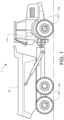
Fig. 1 is a lateral side view illustrating an example embodiment of a vehicle in the form of a working machine; -
Fig. 2 is a schematic illustration of a heat management system according to an example embodiment; -
Fig. 3 is a schematic illustration of a heat management system according to an example embodiment; and -
Fig. 4 is a flow chart of a method of controlling a heat management system according to an example embodiment. - The present invention will now be described more fully hereinafter with reference to the accompanying drawings, in which exemplary embodiments are shown. The invention may, however, be embodied in many different forms and should not be construed as limited to the embodiments set forth herein; rather, these embodiments are provided for thoroughness and completeness. Like reference character refer to like elements throughout the description.
- With particular reference to
Fig. 1 , there is provided a workingmachine 1 exemplified in the form of an articulated hauler. The workingmachine 1 comprises an implement 20 for transporting a load of material. Thus, the workingmachine 1 is arranged to carry material of various kind to different loading and unloading positions. The working machine inFig. 1 comprises anelectric traction motor 101. InFig. 1 , theelectric traction motor 101 is depicted as a wheel hub motor arranged on thefront wheels 102 and therear wheels 104. Theelectric traction motor 101 is thus arranged to generate a torque during propulsion and the generate electric power during braking. - Furthermore, the working
machine 1 comprises a fuel cell system (illustrated inFigs. 2 and3 ). The fuel cell system is arranged to generate electric power when receiving hydrogen and oxygen. The fuel cell system is preferably electrically connected to an energy storage system, e.g. a battery of the working machine, as well as directly electrically connected to theelectric traction motor 101 for feeding electric power to theelectric traction motor 101. As will be described in further detail below, the fuel cell system forms part of a heat management system of the workingmachine 1. - The working
machine 1 is further provided with acontrol unit 114. Thecontrol unit 114 is configured to control various functionalities of the workingmachine 1 and forms part of the material transportation system. - The
control unit 114 may include a microprocessor, microcontroller, programmable digital signal processor or another programmable device. Thecontrol unit 114 may also, or instead, include an application specific integrated circuit, a programmable gate array or programmable array logic, a programmable logic device, or a digital signal processor. Where thecontrol unit 114 includes a programmable device such as the microprocessor, microcontroller or programmable digital signal processor mentioned above, the processor may further include computer executable code that controls operation of the programmable device. - In order to describe the heat management system in further detail, reference is now made to
Fig. 2 . Theheat management system 200 described in the following is particularly advantageous for a workingmachine 1, such as the one depicted inFig. 1 . However, theheat management system 200 is also applicable for other types of working machines provided with electric traction motors for their propulsion, such as e.g. excavators, loaders, etc. Theheat management system 200 may also be implemented in other types of vehicles, such as e.g. trucks, buses, cars, etc. - As described above, and as can be seen in
Fig. 2 , theheat management system 200 comprises afuel cell system 202. Thefuel cell system 202 comprises afuel cell 204. Thefuel cell 204 comprises ahydrogen inlet 206 and ahydrogen outlet 208. Thehydrogen inlet 206 andhydrogen outlet 208 are arranged in fluid communication with a hydrogen tank (not shown). Thefuel cell 204 thus receives hydrogen from the hydrogen tank. Thefuel cell 204 also comprises anoxygen inlet 210 and anoutlet 212. Thefuel cell 204 hence receives oxygen, e.g. air, from theoxygen inlet 210. During operation of thefuel cell 204, electric power is generated by thefuel cell 204 when receiving hydrogen and oxygen. Also, when generating electric power, thefuel cell 204 expels exhaust through the outlet, which exhaust contains atleast exhaust water 214 but sometimes also oxygen to some extent. The electric power generated by thefuel cell 204 is fed to anelectric power system 220 of the workingmachine 1. Theelectric power system 220 preferably comprises an energy storage system (illustrated as 306 inFig. 3 ). Hence, the fuel cell is electrically connected to theelectric power system 220. Although not depicted in the figures, thefuel cell 204 may also be directly connected to theelectric traction motor 101 for feeding electric power to theelectric traction motor 101 without having to pass theelectric power system 220. - Moreover, the
heat management system 200 further comprises acompressor 250. Thecompressor 250 comprises aninlet 252 for receiving a flow ofambient air 254. Theambient air 254 is thus directed through acompressor inlet conduit 256 before entering theinlet 252. Although not depicted in the figures, thecompressor inlet conduit 256 may be provided with a filter such that the ambient air fed into the compressor is relatively clean and free from debris and particles. - Furthermore, the
inlet 252 of thecompressor 250 is arranged in downstream fluid communication with theoutlet 212 of thefuel cell 204. According to the exemplified embodiment depicted inFig. 2 , theoutlet 212 of thefuel cell 204 is connected to anintersection portion 257 of thecompressor inlet conduit 256 at a position upstream theinlet 252. Thus, a fuelcell outlet conduit 213 is arranged between theoutlet 212 and theintersection portion 257. Thecompressor 250 hereby receives a mixture ofexhaust water 214 expelled from thefuel cell 204 andambient air 254. Thecompressor 250 pressurizes the mixture ofexhaust water 214 andambient air 254 and feeds the pressurized mixture towards the ambient environment via acompressor outlet conduit 258. In further detail, thecompressor 250 will pressurize the mixture ofexhaust water 214 andambient air 254, which mixture will be transformed into heated steam which is directed towards the ambient environment. - In the example embodiment depicted in
Fig. 2 , thecompressor 250 is connected to, and operated by, anelectric machine 260. Acompressor shaft 262 is mechanically connecting theelectric machine 260 and thecompressor 250 to each other. Theelectric machine 260 is in turn electrically connected to theelectric power system 220. During e.g. braking using theelectric traction motor 101, theelectric power system 220 can be configured to feed electric power generated by theelectric traction motor 101 to theelectric machine 260 for operating thecompressor 250. This may be particularly advantageous if theelectric traction motor 101 generates surplus electric power that can not be absorbed by the energy storage system. Theelectric machine 260 is hereby operable to dissipate such surplus electric power by controlling the compressor to pressurize the mixture ofexhaust water 214 andambient air 256. It should thus be readily understood that theelectric machine 260 is different from theelectric traction motor 101 depicted inFig. 1 and described above. - The
compressor 250 may however be operated by other means than the above describedelectric machine 260. For example, thecompressor 250 may be connected to, and operable by, an electric traction motor shaft (not shown) of one of theelectric traction motors 101. Thecompressor 250 is in such case a mechanically operated compressor. During e.g. braking, thecompressor 250 is controllably connected to the electric traction motor shaft and acts as an inertia, which reduces the level of electric power generated by the electric traction motor. As a still further example, the compressor may be an electrically controlled compressor operable by electric power received directly from e.g. theelectric power system 220. - In order to describe the
heat management system 200 according to another example embodiment, reference is now made toFig. 3 . The features described above in relation toFig. 2 are also included in the embodiment described in the following. However, for simplifying the reading, some of the features are not included in the illustration described below. - As depicted in
Fig. 3 , theheat management system 200 comprises anair heating arrangement 302. Theair heating arrangement 302 is arranged in downstream fluid communication from thecompressor 250, i.e. the pressurized mixture of exhaust water and ambient air is fed to theair heating arrangement 302 via thecompressor outlet conduit 258. Hence, theair heating arrangement 302 is arranged in thecompressor outlet conduit 258. Theair heating arrangement 302 is preferably an electrical brake resistor. The electrical brake resistor comprises an electric resistive material (not shown) connected to theelectric power system 220. Theelectric power system 220 can hereby feed surplus electric power to the electrical brake resistor when there is a desire to dissipate electric power. Such situation may occur when generating electric power by theelectric traction motor 101 during braking. In further detail, when theenergy storage system 306 is unable to be charged by electric power, or when there is a desire for other reasons of not feeding electric power to theenergy storage system 306, the electrical brake resistor can be used for dissipating electric power. - Moreover, the
energy storage system 200 may also comprise amuffler 304 in thecompressor outlet conduit 258. Preferably, themuffler 304 is arranged in downstream fluid communication with the outlet of thecompressor 250, more preferably also downstream theair heating arrangement 302. - As is also depicted in
Fig. 3 , theheat management system 200 also comprises acondenser 310 and awater tank 312 in fluid communication between theoutlet 212 of the fuel cell and the inlet of thecompressor 250. In further detail, thecondenser 310 and thewater tank 312 are arranged in the fuelcell outlet conduit 213, where thewater tank 312 is arranged in downstream fluid communication with thecondenser 310. Thewater tank 312 is also connected to awater conditioner 314. Thewater tank 312 expelled from the fuel cell can thus be stored in thewater tank 312 and conditioned by thewater conditioner 314 for being better fit to enter thecompressor 250. - Moreover, the
heat management system 200 also comprises avalve 316. Thevalve 316 is connected to thecontrol unit 114 and the control unit thus controls thevalve 316 to assume an open position in which water from thefuel cell 202 is allowed to enter the inlet of thecompressor 250, as well as to control thevalve 316 to assume a closed position in which the water from thefuel cell 202 is prevented from reaching the inlet of thecompressor 250. During operation of thefuel cell 202 and thevalve 316 is closed, the water level in thewater tank 312 will increase, i.e. raise. When the valve is opened, the water level will reduce. - Furthermore, during operation of the working
machine 1 and now also with reference toFig. 4 , thecontrol unit 114 is also configured to determine S1 an electric power absorption capability of theenergy storage system 306. In detail, thecontrol unit 114 determines how much electric power theenergy storage system 306 is able to obtain. Thecontrol unit 114 compares S2 the electric power absorption capability with a level of electric power generated by theelectric traction motor 101 during braking. If the level of electric power generated by theelectric traction motor 101 exceeds the electric power absorption capability, thecontrol unit 114 controls theelectric power system 220 to feed electric power to theelectric machine 260 for operating thecompressor 250. Thecontrol unit 114 can also in such situation control the valve to assume an open position to allow exhaust water from the fuel cell to enter the inlet of thecompressor 250. Thecontrol unit 114 may also control theelectric power system 220 to feed electric power to theair heating arrangement 302 for increasing the electric power dissipation. - It is to be understood that the present disclosure is not limited to the embodiments described above and illustrated in the drawings; rather, the skilled person will recognize that many changes and modifications may be made within the scope of the appended claims.
Claims (15)
- A heat management system for a fuel cell vehicle propelled by an electric traction motor, the heat management system comprising:- a fuel cell system comprising a fuel cell configured to generate electric power when receiving hydrogen through a hydrogen inlet and oxygen through an oxygen inlet, wherein the fuel cell comprises an outlet configured to expel exhaust water formed in the fuel cell, and- a compressor comprising an inlet configured to receive ambient air, and an outlet, wherein the inlet of the compressor is arranged in downstream fluid communication with the outlet of the fuel cell and configured to pressurize a mixture of exhaust water expelled from the fuel cell and ambient air.
- The heat management system according to claim 1, wherein the heat management system further comprises an air heating arrangement arranged in downstream fluid communication with the outlet of the compressor.
- The heat management system according to claim 2, wherein the air heating arrangement is an electrical brake resistor, the electrical brake resistor comprises an electric resistive material connectable to the electric power system.
- The heat management system according to any one of the preceding claims, wherein the fuel cell system comprises a water tank arranged in fluid communication between the outlet of the fuel cell and the inlet of the compressor.
- The heat management system according to any one of the preceding claims, wherein the fuel cell system comprises a valve arranged in fluid communication between the outlet of the fuel cell and the inlet of the compressor.
- The heat management system according to any one of the preceding claims, wherein the heat management system further comprises an electric traction motor configured to propel the vehicle and to controllably regenerate electric power during braking of the vehicle.
- The heat management system according to claim 6, wherein the electric traction motor is electrically connected to an electric power system and configured to receive electric power from the electric power system during propulsion, and to feed electric power to the electric power system during braking.
- The heat management system according to any one of claims 6 or 7, wherein the electric power system comprises an energy storage system configured to receive electric power from the electric traction motor during braking.
- The heat management system according to claim 8, wherein the energy storage system is electrically connected to the fuel cell and configured to receive electric power generated by the fuel cell.
- The heat management system according to any one of claims 8 or 9, wherein the heat management system further comprises an electric machine electrically connectable to the electric power system of the vehicle, the electric machine being operable by electric power received from the electric power system, and a control unit connected to the electric power system, the control unit comprising control circuitry configured to:- determine an electric power absorption capability of the energy storage system,- compare the electric power absorption capability with a level of electric power generated by the electric traction motor during braking, and- control the electric power system to feed electric power to the electric machine for operating the compressor when the level of electric power generated by the electric traction motor exceeds the electric power absorption capability.
- The heat management system according to claim 10, wherein the control unit is connected to the fuel cell system, the control circuitry being further configured to:- control the fuel cell system to feed exhaust water to the inlet of the compressor when the electric power generated by the electric traction motor exceeds the electric power absorption capability.
- A method of controlling a heat management system of a fuel cell vehicle, the heat management system comprising- a fuel cell system comprising a fuel cell configured to generate electric power when receiving hydrogen through a hydrogen inlet and oxygen through an oxygen inlet, wherein the fuel cell comprises an outlet configured to expel exhaust water formed in the fuel cell,- a compressor comprising an inlet configured to receive ambient air and an outlet, wherein the inlet of the compressor is arranged in downstream fluid communication with the outlet of the fuel cell,- an electric power system, and- an electric traction motor configured to propel the vehicle and to generate electric power during braking, the electric traction motor being electrically connected to the electric power system,wherein the method comprises:- determining an electric power absorption capability of an energy storage system of the electric power system,- comparing the electric power absorption capability with a level of electric power generated by the electric traction motor during braking, and- controlling the compressor to pressurize a mixture of exhaust water expelled from the fuel cell and ambient air when the level of electric power generated by the electric traction motor exceeds the electric power absorption capability.
- A fuel cell vehicle, comprising a heat management system according to any one of claims 1 - 11.
- A computer program comprising program code means for performing the steps of claim 12 when the program is run on a computer.
- A computer readable medium carrying a computer program comprising program means for performing the steps of claim 12 when the program means is run on a computer.
Priority Applications (3)
| Application Number | Priority Date | Filing Date | Title |
|---|---|---|---|
| EP22161874.7A EP4246632A1 (en) | 2022-03-14 | 2022-03-14 | A heat management system for a fuel cell vehicle |
| US18/118,382 US12617314B2 (en) | 2022-03-14 | 2023-03-07 | Heat management system for a fuel cell vehicle |
| CN202310225555.5A CN116759606A (en) | 2022-03-14 | 2023-03-09 | Thermal management system for fuel cell vehicles |
Applications Claiming Priority (1)
| Application Number | Priority Date | Filing Date | Title |
|---|---|---|---|
| EP22161874.7A EP4246632A1 (en) | 2022-03-14 | 2022-03-14 | A heat management system for a fuel cell vehicle |
Publications (1)
| Publication Number | Publication Date |
|---|---|
| EP4246632A1 true EP4246632A1 (en) | 2023-09-20 |
Family
ID=80738679
Family Applications (1)
| Application Number | Title | Priority Date | Filing Date |
|---|---|---|---|
| EP22161874.7A Pending EP4246632A1 (en) | 2022-03-14 | 2022-03-14 | A heat management system for a fuel cell vehicle |
Country Status (3)
| Country | Link |
|---|---|
| US (1) | US12617314B2 (en) |
| EP (1) | EP4246632A1 (en) |
| CN (1) | CN116759606A (en) |
Citations (4)
| Publication number | Priority date | Publication date | Assignee | Title |
|---|---|---|---|---|
| US6350536B1 (en) * | 1998-10-07 | 2002-02-26 | Kabushiki Kaisha Toyoda Jidoshokki Seisakusho | Method for preventing compressor from freezing in automobile fuel cell system |
| JP2009026498A (en) * | 2007-07-17 | 2009-02-05 | Nippon Soken Inc | Fuel cell vehicle |
| US20110244343A1 (en) * | 2010-03-31 | 2011-10-06 | Honda Motor Co., Ltd. | Fuel cell system including water injection device |
| US20150349361A1 (en) * | 2014-05-29 | 2015-12-03 | Hyundai Motor Company | Air humidification device and air humidification method for fuel cell using injector |
Family Cites Families (12)
| Publication number | Priority date | Publication date | Assignee | Title |
|---|---|---|---|---|
| US6488345B1 (en) | 2001-08-16 | 2002-12-03 | General Motors Corporation | Regenerative braking system for a batteriless fuel cell vehicle |
| US7781084B2 (en) * | 2004-05-18 | 2010-08-24 | Gm Global Technology Operations, Inc. | Cathode humidification of a PEM fuel cell through exhaust gas recirculation into a positive displacement compressor |
| WO2012128770A1 (en) | 2011-03-24 | 2012-09-27 | International Truck Intellectual Property Company, Llc | Control system for vehicle equipped for regenerative braking |
| KR101416397B1 (en) * | 2013-03-19 | 2014-07-08 | 현대자동차 주식회사 | Fuel cell system and the operating method thereof |
| JP6351301B2 (en) | 2014-02-27 | 2018-07-04 | ダイハツ工業株式会社 | Vehicle control device |
| KR101886515B1 (en) * | 2016-10-18 | 2018-08-07 | 현대자동차주식회사 | Fuel cell system and method for controlling the same |
| JP6919492B2 (en) | 2017-10-18 | 2021-08-18 | トヨタ自動車株式会社 | How to control fuel cell vehicles and fuel cell vehicles |
| JP7003756B2 (en) * | 2018-03-16 | 2022-02-04 | トヨタ自動車株式会社 | Fuel cell system and its control method |
| JP7070241B2 (en) | 2018-08-24 | 2022-05-18 | トヨタ自動車株式会社 | Fuel cell system |
| US11211619B2 (en) * | 2019-10-11 | 2021-12-28 | GM Global Technology Operations LLC | Fuel cell architectures, aftertreatment systems, and control logic for exhaust water extraction |
| KR102791258B1 (en) * | 2019-11-20 | 2025-04-08 | 현대자동차주식회사 | Apparatus for controlling concentration of exhaust hydrogen in fuel cell system and method thereof |
| KR102829847B1 (en) | 2020-05-11 | 2025-07-04 | 현대자동차주식회사 | Regenerative braking control system for motor driving vehicle |
-
2022
- 2022-03-14 EP EP22161874.7A patent/EP4246632A1/en active Pending
-
2023
- 2023-03-07 US US18/118,382 patent/US12617314B2/en active Active
- 2023-03-09 CN CN202310225555.5A patent/CN116759606A/en active Pending
Patent Citations (4)
| Publication number | Priority date | Publication date | Assignee | Title |
|---|---|---|---|---|
| US6350536B1 (en) * | 1998-10-07 | 2002-02-26 | Kabushiki Kaisha Toyoda Jidoshokki Seisakusho | Method for preventing compressor from freezing in automobile fuel cell system |
| JP2009026498A (en) * | 2007-07-17 | 2009-02-05 | Nippon Soken Inc | Fuel cell vehicle |
| US20110244343A1 (en) * | 2010-03-31 | 2011-10-06 | Honda Motor Co., Ltd. | Fuel cell system including water injection device |
| US20150349361A1 (en) * | 2014-05-29 | 2015-12-03 | Hyundai Motor Company | Air humidification device and air humidification method for fuel cell using injector |
Non-Patent Citations (1)
| Title |
|---|
| STEINSTRAETER MATTHIAS ET AL: "Range Extension via Electrothermal Recuperation", WORLD ELECTRIC VEHICLE JOURNAL, vol. 11, no. 2, 25 May 2020 (2020-05-25), pages 41, XP055956013, DOI: 10.3390/wevj11020041 * |
Also Published As
| Publication number | Publication date |
|---|---|
| US12617314B2 (en) | 2026-05-05 |
| US20230286417A1 (en) | 2023-09-14 |
| CN116759606A (en) | 2023-09-15 |
Similar Documents
| Publication | Publication Date | Title |
|---|---|---|
| CN111094660B (en) | Hybrid working machine | |
| US8242737B2 (en) | Motor-driven vehicle | |
| CN113635774B (en) | Regenerative braking control system for motor vehicles | |
| US20120085587A1 (en) | Wind Power for Electric Cars | |
| CN112758062B (en) | Combined cooling and water braking system for a vehicle and method for cooling a propulsion device of a vehicle and water braking a pair of wheels of the vehicle | |
| CN103547497A (en) | Hybrid electric vehicle controller and method of controlling a hybrid electric vehicle | |
| US12410840B2 (en) | Vehicle energy management system, vehicle comprising such vehicle energy management system, and method of controlling vehicle energy management system | |
| CN115867444A (en) | Vehicles including thermal regulation systems | |
| US12617314B2 (en) | Heat management system for a fuel cell vehicle | |
| CN108216185B (en) | Control device for hybrid vehicle | |
| US12157469B2 (en) | Excess regenerative braking power distributed to air blower | |
| US12122214B2 (en) | Cooling system, and a method of controlling a cooling system | |
| EP4063182B1 (en) | A braking system, a fuel cell system, and a vehicle comprising a fuel cell system | |
| CN116160854A (en) | Trailer unit for a towing vehicle | |
| US20230182692A1 (en) | Braking system for a vehicle | |
| US20240308296A1 (en) | Cabin Climate Control Assembly | |
| US12202394B2 (en) | Material transportation system | |
| US12103401B2 (en) | Braking system and method of controlling such a braking system | |
| US20020170756A1 (en) | Electric/gasoline driven vehicle | |
| EP4347329B1 (en) | An energy management system, a fuel cell system, a vehicle and a method of controlling an energy management system | |
| US8397852B1 (en) | Multiple-mode vehicle power system | |
| JP2009281351A (en) | Anti-icing device for exhaust heat recovery device, and plug-in hybrid vehicle | |
| JPH0550168U (en) | Magnetic fluid retarder |
Legal Events
| Date | Code | Title | Description |
|---|---|---|---|
| PUAI | Public reference made under article 153(3) epc to a published international application that has entered the european phase |
Free format text: ORIGINAL CODE: 0009012 |
|
| STAA | Information on the status of an ep patent application or granted ep patent |
Free format text: STATUS: THE APPLICATION HAS BEEN PUBLISHED |
|
| AK | Designated contracting states |
Kind code of ref document: A1 Designated state(s): AL AT BE BG CH CY CZ DE DK EE ES FI FR GB GR HR HU IE IS IT LI LT LU LV MC MK MT NL NO PL PT RO RS SE SI SK SM TR |
|
| STAA | Information on the status of an ep patent application or granted ep patent |
Free format text: STATUS: REQUEST FOR EXAMINATION WAS MADE |
|
| 17P | Request for examination filed |
Effective date: 20240215 |
|
| RBV | Designated contracting states (corrected) |
Designated state(s): AL AT BE BG CH CY CZ DE DK EE ES FI FR GB GR HR HU IE IS IT LI LT LU LV MC MK MT NL NO PL PT RO RS SE SI SK SM TR |