EP4246605A1 - Apparatus for producing electrode and electrode roll - Google Patents
Apparatus for producing electrode and electrode roll Download PDFInfo
- Publication number
- EP4246605A1 EP4246605A1 EP22893193.7A EP22893193A EP4246605A1 EP 4246605 A1 EP4246605 A1 EP 4246605A1 EP 22893193 A EP22893193 A EP 22893193A EP 4246605 A1 EP4246605 A1 EP 4246605A1
- Authority
- EP
- European Patent Office
- Prior art keywords
- electrode
- coated
- substrate
- variable ring
- bobbin
- Prior art date
- Legal status (The legal status is an assumption and is not a legal conclusion. Google has not performed a legal analysis and makes no representation as to the accuracy of the status listed.)
- Granted
Links
Images





Classifications
-
- H—ELECTRICITY
- H01—ELECTRIC ELEMENTS
- H01M—PROCESSES OR MEANS, e.g. BATTERIES, FOR THE DIRECT CONVERSION OF CHEMICAL ENERGY INTO ELECTRICAL ENERGY
- H01M4/00—Electrodes
- H01M4/02—Electrodes composed of, or comprising, active material
- H01M4/04—Processes of manufacture in general
-
- H—ELECTRICITY
- H01—ELECTRIC ELEMENTS
- H01M—PROCESSES OR MEANS, e.g. BATTERIES, FOR THE DIRECT CONVERSION OF CHEMICAL ENERGY INTO ELECTRICAL ENERGY
- H01M4/00—Electrodes
- H01M4/02—Electrodes composed of, or comprising, active material
- H01M4/04—Processes of manufacture in general
- H01M4/043—Processes of manufacture in general involving compressing or compaction
- H01M4/0435—Rolling or calendering
-
- B—PERFORMING OPERATIONS; TRANSPORTING
- B05—SPRAYING OR ATOMISING IN GENERAL; APPLYING FLUENT MATERIALS TO SURFACES, IN GENERAL
- B05C—APPARATUS FOR APPLYING FLUENT MATERIALS TO SURFACES, IN GENERAL
- B05C1/00—Apparatus in which liquid or other fluent material is applied to the surface of the work by contact with a member carrying the liquid or other fluent material, e.g. a porous member loaded with a liquid to be applied as a coating
- B05C1/04—Apparatus in which liquid or other fluent material is applied to the surface of the work by contact with a member carrying the liquid or other fluent material, e.g. a porous member loaded with a liquid to be applied as a coating for applying liquid or other fluent material to work of indefinite length
- B05C1/08—Apparatus in which liquid or other fluent material is applied to the surface of the work by contact with a member carrying the liquid or other fluent material, e.g. a porous member loaded with a liquid to be applied as a coating for applying liquid or other fluent material to work of indefinite length using a roller or other rotating member which contacts the work along a generating line
- B05C1/0826—Apparatus in which liquid or other fluent material is applied to the surface of the work by contact with a member carrying the liquid or other fluent material, e.g. a porous member loaded with a liquid to be applied as a coating for applying liquid or other fluent material to work of indefinite length using a roller or other rotating member which contacts the work along a generating line the work being a web or sheets
-
- B—PERFORMING OPERATIONS; TRANSPORTING
- B65—CONVEYING; PACKING; STORING; HANDLING THIN OR FILAMENTARY MATERIAL
- B65H—HANDLING THIN OR FILAMENTARY MATERIAL, e.g. SHEETS, WEBS, CABLES
- B65H75/00—Storing webs, tapes, or filamentary material, e.g. on reels
- B65H75/02—Cores, formers, supports, or holders for coiled, wound, or folded material, e.g. reels, spindles, bobbins, cop tubes, cans, mandrels or chucks
- B65H75/04—Kinds or types
- B65H75/08—Kinds or types of circular or polygonal cross-section
- B65H75/10—Kinds or types of circular or polygonal cross-section without flanges, e.g. cop tubes
-
- H—ELECTRICITY
- H01—ELECTRIC ELEMENTS
- H01M—PROCESSES OR MEANS, e.g. BATTERIES, FOR THE DIRECT CONVERSION OF CHEMICAL ENERGY INTO ELECTRICAL ENERGY
- H01M10/00—Secondary cells; Manufacture thereof
- H01M10/04—Construction or manufacture in general
-
- H—ELECTRICITY
- H01—ELECTRIC ELEMENTS
- H01M—PROCESSES OR MEANS, e.g. BATTERIES, FOR THE DIRECT CONVERSION OF CHEMICAL ENERGY INTO ELECTRICAL ENERGY
- H01M10/00—Secondary cells; Manufacture thereof
- H01M10/04—Construction or manufacture in general
- H01M10/0404—Machines for assembling batteries
- H01M10/0409—Machines for assembling batteries for cells with wound electrodes
-
- H—ELECTRICITY
- H01—ELECTRIC ELEMENTS
- H01M—PROCESSES OR MEANS, e.g. BATTERIES, FOR THE DIRECT CONVERSION OF CHEMICAL ENERGY INTO ELECTRICAL ENERGY
- H01M10/00—Secondary cells; Manufacture thereof
- H01M10/04—Construction or manufacture in general
- H01M10/0431—Cells with wound or folded electrodes
-
- H—ELECTRICITY
- H01—ELECTRIC ELEMENTS
- H01M—PROCESSES OR MEANS, e.g. BATTERIES, FOR THE DIRECT CONVERSION OF CHEMICAL ENERGY INTO ELECTRICAL ENERGY
- H01M4/00—Electrodes
- H01M4/02—Electrodes composed of, or comprising, active material
- H01M4/04—Processes of manufacture in general
- H01M4/0402—Methods of deposition of the material
- H01M4/0404—Methods of deposition of the material by coating on electrode collectors
-
- H—ELECTRICITY
- H01—ELECTRIC ELEMENTS
- H01M—PROCESSES OR MEANS, e.g. BATTERIES, FOR THE DIRECT CONVERSION OF CHEMICAL ENERGY INTO ELECTRICAL ENERGY
- H01M4/00—Electrodes
- H01M4/02—Electrodes composed of, or comprising, active material
- H01M4/13—Electrodes for accumulators with non-aqueous electrolyte, e.g. for lithium-accumulators; Processes of manufacture thereof
- H01M4/139—Processes of manufacture
-
- B—PERFORMING OPERATIONS; TRANSPORTING
- B65—CONVEYING; PACKING; STORING; HANDLING THIN OR FILAMENTARY MATERIAL
- B65H—HANDLING THIN OR FILAMENTARY MATERIAL, e.g. SHEETS, WEBS, CABLES
- B65H2701/00—Handled material; Storage means
- B65H2701/10—Handled articles or webs
- B65H2701/19—Specific article or web
-
- Y—GENERAL TAGGING OF NEW TECHNOLOGICAL DEVELOPMENTS; GENERAL TAGGING OF CROSS-SECTIONAL TECHNOLOGIES SPANNING OVER SEVERAL SECTIONS OF THE IPC; TECHNICAL SUBJECTS COVERED BY FORMER USPC CROSS-REFERENCE ART COLLECTIONS [XRACs] AND DIGESTS
- Y02—TECHNOLOGIES OR APPLICATIONS FOR MITIGATION OR ADAPTATION AGAINST CLIMATE CHANGE
- Y02E—REDUCTION OF GREENHOUSE GAS [GHG] EMISSIONS, RELATED TO ENERGY GENERATION, TRANSMISSION OR DISTRIBUTION
- Y02E60/00—Enabling technologies; Technologies with a potential or indirect contribution to GHG emissions mitigation
- Y02E60/10—Energy storage using batteries
Definitions
- the present specification relates to an electrode manufacturing apparatus and an electrode roll.
- a shape of the battery there is a high demand for an angular or pouch-type secondary battery that may have a small thickness and be applied to products such as mobile phones.
- a material there is a high demand for lithium secondary batteries such as lithium-ion batteries or lithium-ion polymer batteries that have advantages such as a high energy density, a discharge voltage, and output stability.
- the secondary battery is structured to include an electrode assembly made by stacking a positive electrode, a negative electrode, and a separator positioned between the positive electrode and the negative electrode.
- the positive and negative electrodes are each manufactured by applying slurry containing an active material onto a current collector.
- the manufactured electrode is stored in a state of being wound around a bobbin before assembling the battery, and is moved when necessary.
- a single current collector may be coated with a plurality of electrodes and stored by being wound around the bobbin.
- a portion of the current collector, which is disposed between the electrodes and is not coated with slurry, may be wrinkled. Accordingly, there is a need for a method capable of solving a problem with storage.
- the present specification is intended to provide an electrode manufacturing apparatus and an electrode roll.
- an electrode manufacturing apparatus including: a supply part configured to supply a substrate; a coating part configured to coat at least one surface of the supplied substrate with an electrode layer divided into coated portions coated with electrode slurry and provided in two or more regions spaced apart from one another in a direction perpendicular to a direction in which the substrate is supplied, and a non-coated portion between the coated portions in the two or more regions; a drying part configured to dry the coated electrode layer to manufacture an electrode film; and a recovery part configured to recover the electrode film, in which the recovery part includes: a bobbin around which the electrode film is wound; and a variable ring fitted with the bobbin and configured to be movable in a longitudinal direction of the bobbin, the variable ring being provided to correspond to a position of the non-coated portion.
- variable ring may be an elastic band.
- a width of the variable ring may be 0.1 or more times and less than 1 time a width of the non-coated portion.
- a thickness of the variable ring may be 1 mm or more and 5 mm or less.
- the coating part may coat at least one surface of the supplied substrate with the electrode layer divided into the coated portions coated with the electrode slurry and provided in the two regions spaced apart from each other in the direction perpendicular to the direction in which the substrate is supplied, and the non-coated portion between the coated portions in the two regions, and the recovery part may include a single variable ring provided to correspond to a position of the non-coated portion.
- the coating part may coat at least one surface of the supplied substrate with the electrode layer divided into the coated portions coated with the electrode slurry and provided in the three regions spaced apart from one another in the direction perpendicular to the direction in which the substrate is supplied, and the two non-coated portions respectively positioned between the coated portions in the three regions, and the recovery part may include two variable rings provided to respectively correspond to positions of the two non-coated portions.
- an electrode roll including: an electrode film including a substrate, and an electrode layer disposed on at least one surface of the substrate and divided into coated portions coated with electrode slurry and provided in two or more regions spaced apart from one another in a longitudinal direction of the substrate, and a non-coated portion provided between the two or more coated portions; a bobbin around which the electrode film is wound; and a variable ring fitted with the bobbin and configured to be movable in a longitudinal direction of the bobbin, the variable ring being provided to correspond to the position of the non-coated portion.
- variable ring may be an elastic band.
- a width of the variable ring may be 0.1 or more times and less than 1 time a width of the non-coated portion.
- a thickness of the variable ring may be 1 mm or more and 5 mm or less.
- the electrode layer may be disposed on at least one surface of the substrate and divided into the coated portions disposed in the two regions spaced apart from each other in the longitudinal direction of the substrate, and the non-coated portion provided between the coated portions in the two regions, and the variable ring may be provided to correspond to a position of the non-coated portion.
- the electrode layer may be disposed on at least one surface of the substrate and divided into the coated portions provided in the three regions spaced apart from one another in the longitudinal direction of the substrate, and the two non-coated portions respectively provided between the coated portions in the three regions, and the variable rings may be provided to respectively correspond to positions of the two non-coated portions.
- An embodiment of the present specification may advantageously reduce wrinkles that may occur between the plurality of electrodes formed on the single substrate.
- An embodiment of the present specification may advantageously reduce the thickness difference between the non-coated portion and the coated portion coated with the electrode.
- An embodiment of the present specification may advantageously reduce differences in physical characteristics between the non-coated portion and the coated portion coated with the electrode.
- FIG. 1 is a block diagram illustrating an electrode manufacturing apparatus 500 according to an embodiment of the present specification
- FIG. 2 is a cross-sectional view illustrating the electrode manufacturing apparatus 500 according to an embodiment of the present specification.
- the electrode manufacturing apparatus 500 includes a supply part 100, a coating part 200, a drying part 300, and a recovery part 400.
- the recovery part 400 includes: a bobbin 410 around which the electrode film 30 is wound; and a variable ring fitted with the bobbin 410 and configured to be movable in a longitudinal direction of the bobbin 410, the variable ring being provided to correspond to a position of a non-coated portion 22 provided between coated portions 21 of an electrode film that are coated with electrode slurry.
- a variable ring 420 is provided to correspond to a position of the non-coated portion 22 provided between the coated portions 21 of the electrode film that are coated with the electrode slurry, a level difference between the non-coated portion 22 and the coated portion 21 coated with the electrode decreases, thereby reducing the occurrence of wrinkles.
- the variable ring 420 may be a ring made of an elastic material, specifically, an elastic band.
- the material is not particularly limited as long as the material has appropriate rubber elasticity and mechanical strength, excellent wear resistance, and a small frictional coefficient. Rubber such as urethane rubber, natural rubber, acrylic rubber, or the like may be used as the material.
- the variable ring 420 provides an elastic force, such that the variable ring 420 may be easily moved in accordance with a position of the non-coated portion 22 of the electrode film, which is a recovery target, and the variable ring 420 is positioned to be in close contact with a surface of a bobbin after being moved, such that a designated position is not easily changed during the process.
- variable ring may be deformed in shape by a force. Therefore, even though the amount of force applied to a center of the bobbin is increased by the electrode film wound in multiple layers, the variable ring may cope with the increase in force while being appropriately deformed in shape.
- a width W of the variable ring 420 may be 0.1 or more times and less than 1 time, 0.2 or more times and less than 1 time, 0.3 or more times and less than 1 time, 0.4 or more times and less than 1 time, 0.5 or more times and less than 1 time, 0.6 or more times and less than 1 time, 0.7 or more times and less than 1 time, 0.8 or more times and less than 1 time, or 0.9 or more times and less than 1 time a width of the non-coated portion 22.
- a width of the variable ring 420 may be almost equal to a width of the non-coated portion 22.
- variable ring 420 may come into contact with an edge of the coated portion 21 and deform the coated portion 21.
- the width of the variable ring 420 compensates for a level difference from the coated portion 21 without deforming the coated portion 21.
- a thickness H of the variable ring 420 may be selected in consideration of a height of the coated portion 21.
- the thickness H of the variable ring 420 may be 1 mm or more and 10 mm or less, or 1 mm or more and 5 mm or less.
- the thickness H of the variable ring may be implemented by the single variable ring, as illustrated in FIG. 6A .
- a shape of the bobbin 410 is not particularly limited as long as the electrode film may be stored or moved in a state of being wound around the bobbin 410.
- the bobbin 410 may have a cylindrical shape.
- the bobbin 410 may have a shape similar to a shape of a spool.
- a central portion of the bobbin 410 around which the electrode film 30 is wound has a constant diameter, and two opposite ends of the bobbin 410 each have a larger diameter than the central portion of the bobbin 410, which makes it possible to prevent the electrode film 30 wound around the central portion of the bobbin 410 from being separated toward the two opposite ends of the bobbin 410.
- a length of the bobbin 410 is not particularly limited as long as the length of the bobbin 410 is larger than a width of the electrode film 30 and there is no problem occurring when the electrode film 30 is stored.
- a diameter of the bobbin 410 is not particularly limited as long as the bobbin 410 may withstand a physical force applied by the wound electrode film 30 when the electrode film 30 is stored.
- FIG. 7 is a cross-sectional view illustrating an electrode manufacturing apparatus according to still yet another embodiment of the present specification.
- the electrode manufacturing apparatus 500 further includes a cutting part 600 in addition to the supply part 100, the coating part 200, the drying part 300, and the recovery part 400.
- the cutting part 600 has a cutter.
- the cutter may separate a manufactured electrode into two or more pieces by cutting the non-coated portion in a supply direction.
- the recovery parts 400 may be provided to correspond in number to the two or more electrodes separated as described above.
- a facility for manufacturing the electrode having a large width of 1000 mm or more, 1100 mm or more, or 1200 mm or more is advantageous in mass-producing the electrode.
- the single recovery part 400 is provided to correspond in width to the manufactured electrode having a large width, the number of non-coated portions is inevitably increased in a direction perpendicular to the supply direction, and the number of defects is inevitably increased because of a thickness difference between the coated portion and the non-coated portion.
- the cutting part 600 cuts the manufactured electrode having a large width into a width that may allow the variable ring 420 provided on the recovery part 400 to control a defect caused by a thickness difference between the coated portion and the non-coated portion.
- the plurality of recovery parts 400 may be provided to correspond in number to the cut electrodes.
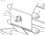
- FIG. 8 is a perspective view illustrating a state in which the cutting part 600 is provided according to another embodiment of the present specification
- FIG. 9 is a cross-sectional view illustrating a state in which the cutting part 600 is provided according to another embodiment of the present specification.
- the cutting part 600 may have two knife wheels 611 and 651 that may cut the electrode while rotating when the electrode moves between the two knife wheels 611 and 651.
- the cutting part 600 may include a lower knife 650 provided below the substrate 10, and an upper knife 610 provided above the substrate 10.
- the upper knife 610 and the lower knife 650 may respectively include the knife wheel 611 and 651, and housings 612 and 652 into which the knife wheel is respectively inserted and fixed.
- Any one of the two knife wheels 611 and 651 may rotate in the same rotation direction as adjacent guide rolls 700 and 700', and the other of the two knife wheels 611 and 651 may rotate in a direction opposite to the rotation direction of the adjacent guide rolls 700 and 700'.
- the rotation directions of the two knife wheels 611 and 651 may be different from each other, but the rotational speeds of the two knife wheels 611 and 651 may be equal to each other. More specifically, the rotational speeds of the two knife wheels 611 and 651 may each be equal to a rotational speed of each of the guide rolls 700 and 700'.
- the supply part 100 serves to supply the substrate 10.
- the configuration for supplying the substrate is not particularly limited as long as the supply part 100 may supply the substrate 10.
- the supply part 100 may supply the substrate 10 by unwinding the substrate 10 from a roll around which the substrate 10 is wound.
- the substrate 10 is not particularly limited as long as the substrate may be coated with electrode slurry.
- the substrate 10 may be a current collector, specifically, a metal foil.
- the substrate may be a foil made of copper, aluminum, or a combination thereof.
- the coating part 200 coats at least one surface of the supplied substrate 10 with the electrode layer divided into the coated portions 21 coated with the electrode slurry and provided in two or more regions spaced apart from one another in the direction perpendicular to the direction in which the substrate 10 is supplied, and the non-coated portions 22 disposed between the coated portions provided in the two or more regions.
- a method of coating electrode slurry by the coating part 200 is not particularly limited.
- a general method of applying electrode slurry using a slot die, a blade, comma coating, or the like may be selected and changed, as necessary.
- the electrode slurry which is to be coated by the coating part 200, may include an electrode active material, a binder, and a solvent.
- the electrode active material is not particularly limited as long as the electrode active material is a material used for a positive electrode or a negative electrode of a battery.
- the electrode active material may be a cobalt-based active material, a ternary active material, a nickel-based active material, a manganese-based active material, a phosphoric acid-based active material, or the like.
- the binder is not particularly limited as long as the binder may coagulate the electrode active material.
- the binder may be polyvinylidene fluoride, styrene-butadiene rubber (SBR), or the like.
- the solvent is not particularly limited as long as the solvent may provide fluidity to the electrode slurry.
- the solvent may be water, N-methyl pyrrolidone, or the like.
- the drying part 300 removes the solvent in the coated electrode slurry by drying the coated electrode layer.
- a drying means of the drying part 300 is not particularly limited. However, the drying means of the drying part 300 may be selected in accordance with characteristics of the electrode slurry that is a target to be dried. At least one of hot blast, a heater, and UV irradiation may be selected.
- a drying temperature and time of the drying part 300 are not particularly limited. However, the drying temperature and time of the drying part 300 may be adjusted depending on characteristics of the electrode slurry that is a target to be dried. For example, the electrode slurry may be dried at a temperature of about 200°C or less for 20 seconds to 5 minutes.
- the coating part 200 may coat at least one surface of the supplied substrate with the electrode layer 20 divided into the coated portions 21 coated with the electrode slurry and provided in the two regions spaced apart from each other in the direction perpendicular to the direction in which the substrate is supplied, and the non-coated portion 22 disposed between the coated portions in the two regions.
- the recovery part 400 may include the single variable ring 420 provided to correspond to the position of the non-coated portion 22.
- the coating part 200 may coat at least one surface of the supplied substrate with the electrode layer 20 divided into the coated portions 21 coated with the electrode slurry and provided in the three regions spaced apart from one another in the direction in which the substrate is supplied, and the two non-coated portions 22 positioned between the coated portions provided in the three regions.
- the recovery part 400 may include the two variable rings 420 provided to correspond to the positions of the two non-coated portions.
- Still another embodiment of the present specification provides an electrode roll including: an electrode film including a substrate, and an electrode layer disposed on at least one surface of the substrate and divided into coated portions coated with electrode slurry and provided in two or more regions spaced apart from one another in a longitudinal direction (supply direction) of the substrate, and non-coated portions provided between the two or more coated portions; a bobbin around which the electrode film is wound; and a variable ring fitted with the bobbin and configured to be movable in a longitudinal direction of the bobbin, the variable ring being provided to correspond to the position of the non-coated portion.
- the description of the electrode roll may be replaced with the description of the electrode manufacturing apparatus.
- the electrode layer 20 may be disposed on at least one surface of the substrate and divided into the coated portions 21 provided in the two regions spaced apart from each other in the longitudinal direction of the substrate, and the non-coated portion 22 provided between the coated portion provided in the two regions.
- the variable ring 420 may be provided to correspond to the position of the non-coated portion 22.
- the electrode layer 20 may be disposed on at least one surface of the substrate and divided into the coated portions 21 provided in three regions spaced apart from one another in the longitudinal direction of the substrate, and the two non-coated portions 22 provided between the coated portions in the three regions.
- the variable rings 420 may be provided to respectively correspond to the positions of the two non-coated portions 22.
Landscapes
- Engineering & Computer Science (AREA)
- Chemical & Material Sciences (AREA)
- Manufacturing & Machinery (AREA)
- Chemical Kinetics & Catalysis (AREA)
- Electrochemistry (AREA)
- General Chemical & Material Sciences (AREA)
- Materials Engineering (AREA)
- Battery Electrode And Active Subsutance (AREA)
- Coating Apparatus (AREA)
Abstract
Description
- This application claims priority to and the benefit of
Korean Patent Application No. 10-2021-0153117 filed with the Korean Intellectual Property Office on November 9, 2021 - The present specification relates to an electrode manufacturing apparatus and an electrode roll.
- Recently, prices of energy sources have increased because of the depletion of fossil fuels, and the interest in environmental pollution is increasing. Therefore, there is an increasing demand for environmental-friendly alternative energy sources. Therefore, research on various power production technologies such as nuclear power, solar power, wind power, and tidal power is being continuously conducted. In addition, interest in power storage devices for more efficiently using the produced energy is high.
- In particular, as the development of technologies and demands for mobile devices are increased, there is a rapidly increasing demand for batteries as energy sources. Many studies are being conducted on the batteries in order to meet these needs.
- Representatively, regarding a shape of the battery, there is a high demand for an angular or pouch-type secondary battery that may have a small thickness and be applied to products such as mobile phones. Regarding a material, there is a high demand for lithium secondary batteries such as lithium-ion batteries or lithium-ion polymer batteries that have advantages such as a high energy density, a discharge voltage, and output stability.
- In general, the secondary battery is structured to include an electrode assembly made by stacking a positive electrode, a negative electrode, and a separator positioned between the positive electrode and the negative electrode. The positive and negative electrodes are each manufactured by applying slurry containing an active material onto a current collector. The manufactured electrode is stored in a state of being wound around a bobbin before assembling the battery, and is moved when necessary.
- To improve efficiency of an electrode coating process, a single current collector may be coated with a plurality of electrodes and stored by being wound around the bobbin. However, in this case, a portion of the current collector, which is disposed between the electrodes and is not coated with slurry, may be wrinkled. Accordingly, there is a need for a method capable of solving a problem with storage.
- The present specification is intended to provide an electrode manufacturing apparatus and an electrode roll.
- One embodiment of the present specification provides an electrode manufacturing apparatus including: a supply part configured to supply a substrate; a coating part configured to coat at least one surface of the supplied substrate with an electrode layer divided into coated portions coated with electrode slurry and provided in two or more regions spaced apart from one another in a direction perpendicular to a direction in which the substrate is supplied, and a non-coated portion between the coated portions in the two or more regions; a drying part configured to dry the coated electrode layer to manufacture an electrode film; and a recovery part configured to recover the electrode film, in which the recovery part includes: a bobbin around which the electrode film is wound; and a variable ring fitted with the bobbin and configured to be movable in a longitudinal direction of the bobbin, the variable ring being provided to correspond to a position of the non-coated portion.
- In an embodiment of the present specification, the variable ring may be an elastic band.
- In another embodiment of the present specification, a width of the variable ring may be 0.1 or more times and less than 1 time a width of the non-coated portion.
- In yet another embodiment of the present specification, a thickness of the variable ring may be 1 mm or more and 5 mm or less.
- In an embodiment of the present specification, the coating part may coat at least one surface of the supplied substrate with the electrode layer divided into the coated portions coated with the electrode slurry and provided in the two regions spaced apart from each other in the direction perpendicular to the direction in which the substrate is supplied, and the non-coated portion between the coated portions in the two regions, and the recovery part may include a single variable ring provided to correspond to a position of the non-coated portion.
- In an embodiment of the present specification, the coating part may coat at least one surface of the supplied substrate with the electrode layer divided into the coated portions coated with the electrode slurry and provided in the three regions spaced apart from one another in the direction perpendicular to the direction in which the substrate is supplied, and the two non-coated portions respectively positioned between the coated portions in the three regions, and the recovery part may include two variable rings provided to respectively correspond to positions of the two non-coated portions.
- Another embodiment of the present specification provides an electrode roll including: an electrode film including a substrate, and an electrode layer disposed on at least one surface of the substrate and divided into coated portions coated with electrode slurry and provided in two or more regions spaced apart from one another in a longitudinal direction of the substrate, and a non-coated portion provided between the two or more coated portions; a bobbin around which the electrode film is wound; and a variable ring fitted with the bobbin and configured to be movable in a longitudinal direction of the bobbin, the variable ring being provided to correspond to the position of the non-coated portion.
- In an embodiment of the present specification, the variable ring may be an elastic band.
- In another embodiment of the present specification, a width of the variable ring may be 0.1 or more times and less than 1 time a width of the non-coated portion.
- In yet another embodiment of the present specification, a thickness of the variable ring may be 1 mm or more and 5 mm or less.
- In an embodiment of the present specification, the electrode layer may be disposed on at least one surface of the substrate and divided into the coated portions disposed in the two regions spaced apart from each other in the longitudinal direction of the substrate, and the non-coated portion provided between the coated portions in the two regions, and the variable ring may be provided to correspond to a position of the non-coated portion.
- In an embodiment of the present specification, the electrode layer may be disposed on at least one surface of the substrate and divided into the coated portions provided in the three regions spaced apart from one another in the longitudinal direction of the substrate, and the two non-coated portions respectively provided between the coated portions in the three regions, and the variable rings may be provided to respectively correspond to positions of the two non-coated portions.
- An embodiment of the present specification may advantageously reduce wrinkles that may occur between the plurality of electrodes formed on the single substrate.
- An embodiment of the present specification may advantageously reduce the thickness difference between the non-coated portion and the coated portion coated with the electrode.
- An embodiment of the present specification may advantageously reduce differences in physical characteristics between the non-coated portion and the coated portion coated with the electrode.
-
-
FIG. 1 is a block diagram illustrating an electrode manufacturing apparatus according to an embodiment of the present specification. -
FIG. 2 is a cross-sectional view illustrating the electrode manufacturing apparatus according to an embodiment of the present specification. -
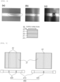
FIG. 3A is a perspective view made before a recovery part recovers an electrode film, andFIG. 3B is a perspective view made after the recovery part completely recovers the electrode film. -
FIGS. 4A, 4B, and 4C are views respectively illustrating Cases 1 to 3 in which non-coated portions of the electrode film recovered, as illustrated inFIGS. 3A and 3B , are wrinkled. - FIG. 5A is a perspective view made before the recovery part recovers an electrode film having two non-coated portions according to an embodiment of the present specification, and FIG. 5B is a perspective view made before the recovery part recovers an electrode film having a single non-coated portion.
-
FIG. 6A is a cross-sectional view of a bobbin having a variable ring according to an embodiment of the present specification,FIG. 6B is a cross-sectional view of a bobbin having a variable ring according to another embodiment of the present specification, andFIG. 6C is an enlarged view of a bobbin having a variable ring according to still another embodiment of the present specification. -
FIG. 7 is a cross-sectional view illustrating an electrode manufacturing apparatus according to still yet another embodiment of the present specification. -
FIG. 8 is a perspective view illustrating a state in which a cutting part is provided according to another embodiment of the present specification. -
FIG. 9 is a cross-sectional view illustrating a state in which a cutting part is provided according to another embodiment of the present specification. -
- 10: Substrate
- 20: Electrode layer
- 21: Coated portion
- 22: Non-coated portion
- 23: Edge portion
- 30: Electrode film
- 100: Supply part
- 200: Coating part
- 300: Drying part
- 400, 400': Recovery part
- 410: Bobbin
- 420: Variable ring
- 420': First variable ring
- 420": Second variable ring
- 500: Electrode manufacturing apparatus
- 600: Cutting part
- 610: Upper knife
- 650: Lower knife
- 611, 651: Knife wheel
- 612, 652: Housing
- Hereinafter, embodiments of the present invention will be described in detail with reference to the drawings. However, the drawings are intended to illustratively describe the present invention, and the scope of the present invention is not limited by the drawings.
-
FIG. 1 is a block diagram illustrating anelectrode manufacturing apparatus 500 according to an embodiment of the present specification, andFIG. 2 is a cross-sectional view illustrating theelectrode manufacturing apparatus 500 according to an embodiment of the present specification. Theelectrode manufacturing apparatus 500 includes asupply part 100, acoating part 200, a dryingpart 300, and arecovery part 400. - The
recovery part 400 includes: abobbin 410 around which theelectrode film 30 is wound; and a variable ring fitted with thebobbin 410 and configured to be movable in a longitudinal direction of thebobbin 410, the variable ring being provided to correspond to a position of anon-coated portion 22 provided betweencoated portions 21 of an electrode film that are coated with electrode slurry. - As illustrated in
FIG. 3A , in case that anelectrode film 30, which has anon-coated portion 22 provided between coated portions coated with electrode slurry, is wound around a bobbin having no variable ring, the indicated portion, i.e., the non-coated portion is wrinkled after a winding operation is completed, as illustrated inFIG. 3B , as in Cases 1 to 3 illustrated inFIGS. 4A to 4C . When the coated electrode is dried and then finally wound, the non-coated portion, which is mainly disposed at a center of the electrode, is wrinkled because of a thickness difference between the coated portion and the non-coated portion. A degree to which the wrinkle is formed increases as a thickness of a foil, which is a substrate, decreases, the amount of coating on the electrode relatively increases, and a thickness of the coated portion increases. - In contrast, as illustrated in
FIG. 5 , in case that avariable ring 420 is provided to correspond to a position of thenon-coated portion 22 provided between thecoated portions 21 of the electrode film that are coated with the electrode slurry, a level difference between thenon-coated portion 22 and thecoated portion 21 coated with the electrode decreases, thereby reducing the occurrence of wrinkles. - The
variable ring 420 may be a ring made of an elastic material, specifically, an elastic band. The material is not particularly limited as long as the material has appropriate rubber elasticity and mechanical strength, excellent wear resistance, and a small frictional coefficient. Rubber such as urethane rubber, natural rubber, acrylic rubber, or the like may be used as the material. In this case, thevariable ring 420 provides an elastic force, such that thevariable ring 420 may be easily moved in accordance with a position of thenon-coated portion 22 of the electrode film, which is a recovery target, and thevariable ring 420 is positioned to be in close contact with a surface of a bobbin after being moved, such that a designated position is not easily changed during the process. In addition, the variable ring may be deformed in shape by a force. Therefore, even though the amount of force applied to a center of the bobbin is increased by the electrode film wound in multiple layers, the variable ring may cope with the increase in force while being appropriately deformed in shape. - A width W of the
variable ring 420 may be 0.1 or more times and less than 1 time, 0.2 or more times and less than 1 time, 0.3 or more times and less than 1 time, 0.4 or more times and less than 1 time, 0.5 or more times and less than 1 time, 0.6 or more times and less than 1 time, 0.7 or more times and less than 1 time, 0.8 or more times and less than 1 time, or 0.9 or more times and less than 1 time a width of thenon-coated portion 22. A width of thevariable ring 420 may be almost equal to a width of thenon-coated portion 22. However, in case that the width of thevariable ring 420 is equal to or larger than the width of thenon-coated portion 22, thevariable ring 420 may come into contact with an edge of the coatedportion 21 and deform the coatedportion 21. When the above-mentioned range is satisfied, the width of thevariable ring 420 compensates for a level difference from the coatedportion 21 without deforming the coatedportion 21. - A thickness H of the
variable ring 420 may be selected in consideration of a height of the coatedportion 21. Specifically, the thickness H of thevariable ring 420 may be 1 mm or more and 10 mm or less, or 1 mm or more and 5 mm or less. In this case, the thickness H of the variable ring may be implemented by the single variable ring, as illustrated inFIG. 6A . Alternatively, as illustrated inFIG. 6B , the target thickness H (H=H1+H2) of the variable ring may be implemented by stacking two or more variable rings, i.e., stacking a first variable ring 420' having a thickness of H1 and a secondvariable ring 420" having a thickness of H2. - A shape of the
bobbin 410 is not particularly limited as long as the electrode film may be stored or moved in a state of being wound around thebobbin 410. Thebobbin 410 may have a cylindrical shape. - The
bobbin 410 may have a shape similar to a shape of a spool. In this case, a central portion of thebobbin 410 around which theelectrode film 30 is wound has a constant diameter, and two opposite ends of thebobbin 410 each have a larger diameter than the central portion of thebobbin 410, which makes it possible to prevent theelectrode film 30 wound around the central portion of thebobbin 410 from being separated toward the two opposite ends of thebobbin 410. - A length of the
bobbin 410 is not particularly limited as long as the length of thebobbin 410 is larger than a width of theelectrode film 30 and there is no problem occurring when theelectrode film 30 is stored. - A diameter of the
bobbin 410 is not particularly limited as long as thebobbin 410 may withstand a physical force applied by thewound electrode film 30 when theelectrode film 30 is stored. -
FIG. 7 is a cross-sectional view illustrating an electrode manufacturing apparatus according to still yet another embodiment of the present specification. Theelectrode manufacturing apparatus 500 further includes a cuttingpart 600 in addition to thesupply part 100, thecoating part 200, the dryingpart 300, and therecovery part 400. - The cutting
part 600 has a cutter. The cutter may separate a manufactured electrode into two or more pieces by cutting the non-coated portion in a supply direction. Therecovery parts 400 may be provided to correspond in number to the two or more electrodes separated as described above. - A facility for manufacturing the electrode having a large width of 1000 mm or more, 1100 mm or more, or 1200 mm or more is advantageous in mass-producing the electrode. However, in case that the
single recovery part 400 is provided to correspond in width to the manufactured electrode having a large width, the number of non-coated portions is inevitably increased in a direction perpendicular to the supply direction, and the number of defects is inevitably increased because of a thickness difference between the coated portion and the non-coated portion. - Before the manufactured electrode having a large width is wound around the
recovery part 400 at a distal end of the facility, the cuttingpart 600 cuts the manufactured electrode having a large width into a width that may allow thevariable ring 420 provided on therecovery part 400 to control a defect caused by a thickness difference between the coated portion and the non-coated portion. The plurality ofrecovery parts 400 may be provided to correspond in number to the cut electrodes. -
FIG. 8 is a perspective view illustrating a state in which thecutting part 600 is provided according to another embodiment of the present specification, andFIG. 9 is a cross-sectional view illustrating a state in which thecutting part 600 is provided according to another embodiment of the present specification. - The cutting
part 600 may have twoknife wheels knife wheels part 600 may include alower knife 650 provided below thesubstrate 10, and anupper knife 610 provided above thesubstrate 10. Theupper knife 610 and thelower knife 650 may respectively include theknife wheel housings - Any one of the two
knife wheels knife wheels - The rotation directions of the two
knife wheels knife wheels knife wheels - The
supply part 100 serves to supply thesubstrate 10. The configuration for supplying the substrate is not particularly limited as long as thesupply part 100 may supply thesubstrate 10. Thesupply part 100 may supply thesubstrate 10 by unwinding thesubstrate 10 from a roll around which thesubstrate 10 is wound. - In this case, the
substrate 10 is not particularly limited as long as the substrate may be coated with electrode slurry. Thesubstrate 10 may be a current collector, specifically, a metal foil. The substrate may be a foil made of copper, aluminum, or a combination thereof. - The
coating part 200 coats at least one surface of the suppliedsubstrate 10 with the electrode layer divided into thecoated portions 21 coated with the electrode slurry and provided in two or more regions spaced apart from one another in the direction perpendicular to the direction in which thesubstrate 10 is supplied, and thenon-coated portions 22 disposed between the coated portions provided in the two or more regions. - A method of coating electrode slurry by the
coating part 200 is not particularly limited. A general method of applying electrode slurry using a slot die, a blade, comma coating, or the like may be selected and changed, as necessary. - The electrode slurry, which is to be coated by the
coating part 200, may include an electrode active material, a binder, and a solvent. - The electrode active material is not particularly limited as long as the electrode active material is a material used for a positive electrode or a negative electrode of a battery. The electrode active material may be a cobalt-based active material, a ternary active material, a nickel-based active material, a manganese-based active material, a phosphoric acid-based active material, or the like.
- The binder is not particularly limited as long as the binder may coagulate the electrode active material. The binder may be polyvinylidene fluoride, styrene-butadiene rubber (SBR), or the like.
- The solvent is not particularly limited as long as the solvent may provide fluidity to the electrode slurry. The solvent may be water, N-methyl pyrrolidone, or the like.
- The drying
part 300 removes the solvent in the coated electrode slurry by drying the coated electrode layer. - A drying means of the drying
part 300 is not particularly limited. However, the drying means of the dryingpart 300 may be selected in accordance with characteristics of the electrode slurry that is a target to be dried. At least one of hot blast, a heater, and UV irradiation may be selected. - A drying temperature and time of the drying
part 300 are not particularly limited. However, the drying temperature and time of the dryingpart 300 may be adjusted depending on characteristics of the electrode slurry that is a target to be dried. For example, the electrode slurry may be dried at a temperature of about 200°C or less for 20 seconds to 5 minutes. - In an embodiment, as illustrated in FIG. 5B, the
coating part 200 may coat at least one surface of the supplied substrate with theelectrode layer 20 divided into thecoated portions 21 coated with the electrode slurry and provided in the two regions spaced apart from each other in the direction perpendicular to the direction in which the substrate is supplied, and thenon-coated portion 22 disposed between the coated portions in the two regions. Therecovery part 400 may include the singlevariable ring 420 provided to correspond to the position of thenon-coated portion 22. - In another embodiment, as illustrated in FIG. 5A, the
coating part 200 may coat at least one surface of the supplied substrate with theelectrode layer 20 divided into thecoated portions 21 coated with the electrode slurry and provided in the three regions spaced apart from one another in the direction in which the substrate is supplied, and the twonon-coated portions 22 positioned between the coated portions provided in the three regions. Therecovery part 400 may include the twovariable rings 420 provided to correspond to the positions of the two non-coated portions. - Still another embodiment of the present specification provides an electrode roll including: an electrode film including a substrate, and an electrode layer disposed on at least one surface of the substrate and divided into coated portions coated with electrode slurry and provided in two or more regions spaced apart from one another in a longitudinal direction (supply direction) of the substrate, and non-coated portions provided between the two or more coated portions; a bobbin around which the electrode film is wound; and a variable ring fitted with the bobbin and configured to be movable in a longitudinal direction of the bobbin, the variable ring being provided to correspond to the position of the non-coated portion.
- In this case, the description of the electrode roll may be replaced with the description of the electrode manufacturing apparatus.
- In an embodiment, as illustrated in FIG. 5B, the
electrode layer 20 may be disposed on at least one surface of the substrate and divided into thecoated portions 21 provided in the two regions spaced apart from each other in the longitudinal direction of the substrate, and thenon-coated portion 22 provided between the coated portion provided in the two regions. Thevariable ring 420 may be provided to correspond to the position of thenon-coated portion 22. - In another embodiment, as illustrated in FIG. 5A, the
electrode layer 20 may be disposed on at least one surface of the substrate and divided into thecoated portions 21 provided in three regions spaced apart from one another in the longitudinal direction of the substrate, and the twonon-coated portions 22 provided between the coated portions in the three regions. The variable rings 420 may be provided to respectively correspond to the positions of the twonon-coated portions 22. - A person skilled in the art may understand that the present invention may be carried out in other specific forms without changing the technical spirit or the essential characteristics of the present invention. Therefore, it should be understood that the above-described embodiments are illustrative in all aspects and do not limit the present invention. The scope of the present invention is represented by the claims rather than the detailed description, and it should be interpreted that the meaning and scope of the claims and various embodiments derived from the equivalent concepts thereto fall within the scope of the present invention.
Claims (12)
- An electrode manufacturing apparatus comprising:a supply part configured to supply a substrate;a coating part configured to coat at least one surface of the supplied substrate with an electrode layer divided into coated portions, wherein the coated portions are coated with an electrode slurry positioned in two or more regions spaced apart from one another in a direction perpendicular to a direction in which the substrate is supplied, and a non-coated portion positioned between the coated portions;a drying part configured to dry the electrode slurry to manufacture an electrode film; anda recovery part configured to recover the electrode film,wherein the recovery part comprises:a bobbin around which the electrode film is wound; anda variable ring fitted with the bobbin and configured to be movable in a longitudinal direction of the bobbin, the variable ring positioned to correspond to a position of the non-coated portion.
- The electrode manufacturing apparatus of claim 1,
wherein the variable ring is an elastic band. - The electrode manufacturing apparatus of claim 1, wherein a width of the variable ring is 0.1 or more times and less than 1 time a width of the non-coated portion.
- The electrode manufacturing apparatus of claim 1, wherein a thickness of the variable ring is 1 mm to 5 mm.
- The electrode manufacturing apparatus of claim 1, wherein the electrode layer is divided into two regions spaced apart from each other and
wherein the recovery part comprises a single variable ring corresponding to the non-coated portion disposed therebetween. - The electrode manufacturing apparatus of claim 1, wherein the electrode slurry is coated in three regions spaced apart from one another with two non-coated portions positioned therebetween, and
wherein the recovery part comprises two variable rings positioned to correspond to positions of the two non-coated portions. - An electrode roll comprising:an electrode film comprising a substrate, and an electrode layer disposed on at least one surface of the substrate and divided into coated portions, wherein the coated portions are coated with an electrode slurry positioned in two or more regions spaced apart from one another in a longitudinal direction of the substrate, and a non-coated portion positioned between two coated portions;a bobbin around which the electrode film is wound; anda variable ring fitted with the bobbin and configured to be movable in a longitudinal direction of the bobbin, the variable ring positioned to correspond to the position of the non-coated portion.
- The electrode roll of claim 7, wherein the variable ring is an elastic band.
- The electrode roll of claim 7, wherein a width of the variable ring is 0.1 or more times and less than 1 time a width of the non-coated portion.
- The electrode roll of claim 7, wherein a thickness of the variable ring is 1 mm to 5 mm.
- The electrode roll of claim 7, wherein the coated portions are disposed in two regions spaced apart from each other in the longitudinal direction of the substrate having the non-coated portion disposed therebetween.
- The electrode roll of claim 7, wherein the coated portions are positioned in three regions in the longitudinal direction of the substrate with two non-coated portions positioned therebetween, and
wherein the variable rings are positioned to correspond to positions of the two non-coated portions.
Applications Claiming Priority (2)
| Application Number | Priority Date | Filing Date | Title |
|---|---|---|---|
| KR20210153117 | 2021-11-09 | ||
| PCT/KR2022/017554 WO2023085773A1 (en) | 2021-11-09 | 2022-11-09 | Apparatus for producing electrode and electrode roll |
Publications (3)
| Publication Number | Publication Date |
|---|---|
| EP4246605A1 true EP4246605A1 (en) | 2023-09-20 |
| EP4246605A4 EP4246605A4 (en) | 2024-08-28 |
| EP4246605B1 EP4246605B1 (en) | 2025-04-02 |
Family
ID=86336161
Family Applications (1)
| Application Number | Title | Priority Date | Filing Date |
|---|---|---|---|
| EP22893193.7A Active EP4246605B1 (en) | 2021-11-09 | 2022-11-09 | Apparatus for producing electrode and electrode roll |
Country Status (7)
| Country | Link |
|---|---|
| US (1) | US20240322111A1 (en) |
| EP (1) | EP4246605B1 (en) |
| JP (1) | JP7636092B2 (en) |
| KR (1) | KR20230067567A (en) |
| ES (1) | ES3023852T3 (en) |
| HU (1) | HUE071138T2 (en) |
| WO (1) | WO2023085773A1 (en) |
Family Cites Families (16)
| Publication number | Priority date | Publication date | Assignee | Title |
|---|---|---|---|---|
| JP2008108742A (en) * | 2007-12-10 | 2008-05-08 | Ube Ind Ltd | Lithium ion battery and manufacturing method thereof |
| JP2010049906A (en) * | 2008-08-21 | 2010-03-04 | Toyota Motor Corp | Manufacturing method of strip electrode, manufacturing apparatus of strip electrode, and manufacturing method of battery |
| US8828102B2 (en) * | 2008-09-02 | 2014-09-09 | Toyota Jidosha Kabushiki Kaisha | Method for manufacturing electrode sheets and apparatus therefor |
| KR101309343B1 (en) * | 2010-09-24 | 2013-09-17 | 가부시끼가이샤 도시바 | Double side applying apparatus and double side applying method |
| JP5617511B2 (en) * | 2010-10-08 | 2014-11-05 | トヨタ自動車株式会社 | Battery sheet manufacturing method and manufacturing apparatus |
| JP2011238628A (en) * | 2011-08-23 | 2011-11-24 | Ube Ind Ltd | Lithium ion battery and method of manufacturing the same |
| CN104067423A (en) * | 2011-12-27 | 2014-09-24 | 株式会社东芝 | Method for producing electrode and method for producing non-aqueous electrolyte battery |
| JP5390721B1 (en) * | 2013-05-08 | 2014-01-15 | 株式会社日立パワーソリューションズ | Roll press method and roll press equipment for electrode material |
| KR101747493B1 (en) * | 2014-07-17 | 2017-06-14 | 주식회사 엘지화학 | Electrode and electrode coating device manufacturing the same |
| KR101830287B1 (en) * | 2015-06-01 | 2018-02-20 | 주식회사 엘지화학 | Electrode Rolling Device Capable of Preventing Swell or Wrinkle of Electrode Sheet by Rolling Work |
| JP2017108072A (en) * | 2015-12-11 | 2017-06-15 | 積水化学工業株式会社 | Electric module manufacturing apparatus and electric module manufacturing method |
| KR102073656B1 (en) * | 2016-02-11 | 2020-02-05 | 주식회사 엘지화학 | Pressing Device Capable of Adjusting Space between Pressing Rolls |
| JP2017183060A (en) * | 2016-03-30 | 2017-10-05 | 株式会社豊田自動織機 | Winding reel |
| KR101810146B1 (en) * | 2016-07-21 | 2017-12-19 | (주)피엔티 | Dryer used in manufacturing electrode of secondary battery |
| KR102206057B1 (en) * | 2018-11-20 | 2021-01-20 | 주식회사 엘지화학 | An electrode rolling apparatus having a heating unit for heating a non-coated portion and Manufacturing system for an electrode comprising the same |
| KR102749928B1 (en) | 2019-04-17 | 2025-01-02 | 아심켐 라이프 사이언스 (톈진) 컴퍼니, 리미티드 | Monooxygenase mutants and their applications |
-
2022
- 2022-11-09 JP JP2023541112A patent/JP7636092B2/en active Active
- 2022-11-09 KR KR1020220148761A patent/KR20230067567A/en active Pending
- 2022-11-09 WO PCT/KR2022/017554 patent/WO2023085773A1/en not_active Ceased
- 2022-11-09 HU HUE22893193A patent/HUE071138T2/en unknown
- 2022-11-09 EP EP22893193.7A patent/EP4246605B1/en active Active
- 2022-11-09 US US18/271,801 patent/US20240322111A1/en active Pending
- 2022-11-09 ES ES22893193T patent/ES3023852T3/en active Active
Also Published As
| Publication number | Publication date |
|---|---|
| JP2024502981A (en) | 2024-01-24 |
| JP7636092B2 (en) | 2025-02-26 |
| CN116669862A (en) | 2023-08-29 |
| KR20230067567A (en) | 2023-05-16 |
| EP4246605B1 (en) | 2025-04-02 |
| EP4246605A4 (en) | 2024-08-28 |
| US20240322111A1 (en) | 2024-09-26 |
| WO2023085773A1 (en) | 2023-05-19 |
| HUE071138T2 (en) | 2025-08-28 |
| ES3023852T3 (en) | 2025-06-03 |
Similar Documents
| Publication | Publication Date | Title |
|---|---|---|
| KR101767636B1 (en) | Press roll for electode sheet | |
| EP3333941B1 (en) | Method for preparing electrode using a roller | |
| JP5108917B2 (en) | Winding device manufacturing equipment | |
| EP1383197B1 (en) | Secondary battery manufacturing method and manufacturing device | |
| US20250054936A1 (en) | Apparatus for Manufacturing Electrode, Method for Manufacturing Electrode, and Electrode Manufactured Thereby | |
| CN106953124B (en) | Winding equipment and mandrels for secondary batteries | |
| US20160351966A1 (en) | Cylindrical electrochemical cells and method of manufacture | |
| CN102136603B (en) | Polymer lithium-ion battery and manufacture method thereof | |
| JP5958300B2 (en) | Electrode manufacturing method and electrode manufacturing apparatus | |
| US11108032B2 (en) | Method and apparatus for manufacturing secondary battery | |
| JP2012033421A (en) | Manufacturing apparatus of wound element | |
| KR20170100378A (en) | Coating Device Reducing Thickness of Overlapping Region and Electrode Manufactured by Using the Same | |
| JP5617511B2 (en) | Battery sheet manufacturing method and manufacturing apparatus | |
| TW202243306A (en) | Battery including folded foil portion and method of fabricating same | |
| JP2010049906A (en) | Manufacturing method of strip electrode, manufacturing apparatus of strip electrode, and manufacturing method of battery | |
| CN105406101A (en) | Rolling device for secondary battery and rolling method for the same | |
| EP4246605B1 (en) | Apparatus for producing electrode and electrode roll | |
| KR20150124611A (en) | Cutting apparatus for secondary battery | |
| CN116669862B (en) | Electrode manufacturing equipment and electrode roll | |
| JP2009181832A (en) | Non-aqueous secondary battery electrode assembly manufacturing equipment | |
| EP4333146B1 (en) | Electrode assembly manufacturing apparatus for preventing separator folding and electrode assembly manufactured using the same | |
| KR102798545B1 (en) | Manufacturing Method and Manufacturing Apparatus of Electrode for Secondary Battery | |
| KR20200056191A (en) | Manufacturing method and manufacturing apparatus for electrode assembly | |
| TW202312535A (en) | Battery with ceramic barrier and method of fabricating same | |
| KR102920239B1 (en) | Method for manufacturing electrode assembly |
Legal Events
| Date | Code | Title | Description |
|---|---|---|---|
| STAA | Information on the status of an ep patent application or granted ep patent |
Free format text: STATUS: THE INTERNATIONAL PUBLICATION HAS BEEN MADE |
|
| PUAI | Public reference made under article 153(3) epc to a published international application that has entered the european phase |
Free format text: ORIGINAL CODE: 0009012 |
|
| STAA | Information on the status of an ep patent application or granted ep patent |
Free format text: STATUS: REQUEST FOR EXAMINATION WAS MADE |
|
| 17P | Request for examination filed |
Effective date: 20230616 |
|
| AK | Designated contracting states |
Kind code of ref document: A1 Designated state(s): AL AT BE BG CH CY CZ DE DK EE ES FI FR GB GR HR HU IE IS IT LI LT LU LV MC ME MK MT NL NO PL PT RO RS SE SI SK SM TR |
|
| A4 | Supplementary search report drawn up and despatched |
Effective date: 20240729 |
|
| RIC1 | Information provided on ipc code assigned before grant |
Ipc: B05C 1/08 20060101ALN20240723BHEP Ipc: H01M 4/139 20100101ALI20240723BHEP Ipc: H01M 10/04 20060101ALI20240723BHEP Ipc: H01M 4/04 20060101AFI20240723BHEP |
|
| GRAP | Despatch of communication of intention to grant a patent |
Free format text: ORIGINAL CODE: EPIDOSNIGR1 |
|
| STAA | Information on the status of an ep patent application or granted ep patent |
Free format text: STATUS: GRANT OF PATENT IS INTENDED |
|
| RIC1 | Information provided on ipc code assigned before grant |
Ipc: B05C 1/08 20060101ALN20240919BHEP Ipc: H01M 4/139 20100101ALI20240919BHEP Ipc: H01M 10/04 20060101ALI20240919BHEP Ipc: H01M 4/04 20060101AFI20240919BHEP |
|
| INTG | Intention to grant announced |
Effective date: 20241008 |
|
| DAV | Request for validation of the european patent (deleted) | ||
| DAX | Request for extension of the european patent (deleted) | ||
| GRAJ | Information related to disapproval of communication of intention to grant by the applicant or resumption of examination proceedings by the epo deleted |
Free format text: ORIGINAL CODE: EPIDOSDIGR1 |
|
| STAA | Information on the status of an ep patent application or granted ep patent |
Free format text: STATUS: REQUEST FOR EXAMINATION WAS MADE |
|
| GRAP | Despatch of communication of intention to grant a patent |
Free format text: ORIGINAL CODE: EPIDOSNIGR1 |
|
| STAA | Information on the status of an ep patent application or granted ep patent |
Free format text: STATUS: GRANT OF PATENT IS INTENDED |
|
| P01 | Opt-out of the competence of the unified patent court (upc) registered |
Free format text: CASE NUMBER: APP_59676/2024 Effective date: 20241104 |
|
| INTC | Intention to grant announced (deleted) | ||
| RIC1 | Information provided on ipc code assigned before grant |
Ipc: B05C 1/08 20060101ALN20241122BHEP Ipc: H01M 4/139 20100101ALI20241122BHEP Ipc: H01M 10/04 20060101ALI20241122BHEP Ipc: H01M 4/04 20060101AFI20241122BHEP |
|
| INTG | Intention to grant announced |
Effective date: 20241210 |
|
| GRAS | Grant fee paid |
Free format text: ORIGINAL CODE: EPIDOSNIGR3 |
|
| GRAA | (expected) grant |
Free format text: ORIGINAL CODE: 0009210 |
|
| STAA | Information on the status of an ep patent application or granted ep patent |
Free format text: STATUS: THE PATENT HAS BEEN GRANTED |
|
| AK | Designated contracting states |
Kind code of ref document: B1 Designated state(s): AL AT BE BG CH CY CZ DE DK EE ES FI FR GB GR HR HU IE IS IT LI LT LU LV MC ME MK MT NL NO PL PT RO RS SE SI SK SM TR |
|
| REG | Reference to a national code |
Ref country code: GB Ref legal event code: FG4D |
|
| REG | Reference to a national code |
Ref country code: CH Ref legal event code: EP |
|
| REG | Reference to a national code |
Ref country code: IE Ref legal event code: FG4D |
|
| REG | Reference to a national code |
Ref country code: DE Ref legal event code: R096 Ref document number: 602022012717 Country of ref document: DE |
|
| REG | Reference to a national code |
Ref country code: ES Ref legal event code: FG2A Ref document number: 3023852 Country of ref document: ES Kind code of ref document: T3 Effective date: 20250603 |
|
| REG | Reference to a national code |
Ref country code: NL Ref legal event code: MP Effective date: 20250402 |
|
| REG | Reference to a national code |
Ref country code: HU Ref legal event code: AG4A Ref document number: E071138 Country of ref document: HU |
|
| PG25 | Lapsed in a contracting state [announced via postgrant information from national office to epo] |
Ref country code: NL Free format text: LAPSE BECAUSE OF FAILURE TO SUBMIT A TRANSLATION OF THE DESCRIPTION OR TO PAY THE FEE WITHIN THE PRESCRIBED TIME-LIMIT Effective date: 20250402 |
|
| REG | Reference to a national code |
Ref country code: AT Ref legal event code: MK05 Ref document number: 1782205 Country of ref document: AT Kind code of ref document: T Effective date: 20250402 |
|
| PG25 | Lapsed in a contracting state [announced via postgrant information from national office to epo] |
Ref country code: FI Free format text: LAPSE BECAUSE OF FAILURE TO SUBMIT A TRANSLATION OF THE DESCRIPTION OR TO PAY THE FEE WITHIN THE PRESCRIBED TIME-LIMIT Effective date: 20250402 Ref country code: PT Free format text: LAPSE BECAUSE OF FAILURE TO SUBMIT A TRANSLATION OF THE DESCRIPTION OR TO PAY THE FEE WITHIN THE PRESCRIBED TIME-LIMIT Effective date: 20250804 |
|
| REG | Reference to a national code |
Ref country code: LT Ref legal event code: MG9D |
|
| PG25 | Lapsed in a contracting state [announced via postgrant information from national office to epo] |
Ref country code: NO Free format text: LAPSE BECAUSE OF FAILURE TO SUBMIT A TRANSLATION OF THE DESCRIPTION OR TO PAY THE FEE WITHIN THE PRESCRIBED TIME-LIMIT Effective date: 20250702 Ref country code: GR Free format text: LAPSE BECAUSE OF FAILURE TO SUBMIT A TRANSLATION OF THE DESCRIPTION OR TO PAY THE FEE WITHIN THE PRESCRIBED TIME-LIMIT Effective date: 20250703 |
|
| PG25 | Lapsed in a contracting state [announced via postgrant information from national office to epo] |
Ref country code: PL Free format text: LAPSE BECAUSE OF FAILURE TO SUBMIT A TRANSLATION OF THE DESCRIPTION OR TO PAY THE FEE WITHIN THE PRESCRIBED TIME-LIMIT Effective date: 20250402 |
|
| PG25 | Lapsed in a contracting state [announced via postgrant information from national office to epo] |
Ref country code: BG Free format text: LAPSE BECAUSE OF FAILURE TO SUBMIT A TRANSLATION OF THE DESCRIPTION OR TO PAY THE FEE WITHIN THE PRESCRIBED TIME-LIMIT Effective date: 20250402 |
|
| PG25 | Lapsed in a contracting state [announced via postgrant information from national office to epo] |
Ref country code: HR Free format text: LAPSE BECAUSE OF FAILURE TO SUBMIT A TRANSLATION OF THE DESCRIPTION OR TO PAY THE FEE WITHIN THE PRESCRIBED TIME-LIMIT Effective date: 20250402 |
|
| PG25 | Lapsed in a contracting state [announced via postgrant information from national office to epo] |
Ref country code: AT Free format text: LAPSE BECAUSE OF FAILURE TO SUBMIT A TRANSLATION OF THE DESCRIPTION OR TO PAY THE FEE WITHIN THE PRESCRIBED TIME-LIMIT Effective date: 20250402 |
|
| PG25 | Lapsed in a contracting state [announced via postgrant information from national office to epo] |
Ref country code: RS Free format text: LAPSE BECAUSE OF FAILURE TO SUBMIT A TRANSLATION OF THE DESCRIPTION OR TO PAY THE FEE WITHIN THE PRESCRIBED TIME-LIMIT Effective date: 20250702 |
|
| PG25 | Lapsed in a contracting state [announced via postgrant information from national office to epo] |
Ref country code: IS Free format text: LAPSE BECAUSE OF FAILURE TO SUBMIT A TRANSLATION OF THE DESCRIPTION OR TO PAY THE FEE WITHIN THE PRESCRIBED TIME-LIMIT Effective date: 20250802 |
|
| PG25 | Lapsed in a contracting state [announced via postgrant information from national office to epo] |
Ref country code: LV Free format text: LAPSE BECAUSE OF FAILURE TO SUBMIT A TRANSLATION OF THE DESCRIPTION OR TO PAY THE FEE WITHIN THE PRESCRIBED TIME-LIMIT Effective date: 20250402 |
|
| PGFP | Annual fee paid to national office [announced via postgrant information from national office to epo] |
Ref country code: HU Payment date: 20251127 Year of fee payment: 4 |
|
| REG | Reference to a national code |
Ref country code: DE Ref legal event code: R097 Ref document number: 602022012717 Country of ref document: DE |
|
| PGFP | Annual fee paid to national office [announced via postgrant information from national office to epo] |
Ref country code: DE Payment date: 20251020 Year of fee payment: 4 |
|
| PG25 | Lapsed in a contracting state [announced via postgrant information from national office to epo] |
Ref country code: SM Free format text: LAPSE BECAUSE OF FAILURE TO SUBMIT A TRANSLATION OF THE DESCRIPTION OR TO PAY THE FEE WITHIN THE PRESCRIBED TIME-LIMIT Effective date: 20250402 Ref country code: DK Free format text: LAPSE BECAUSE OF FAILURE TO SUBMIT A TRANSLATION OF THE DESCRIPTION OR TO PAY THE FEE WITHIN THE PRESCRIBED TIME-LIMIT Effective date: 20250402 |
|
| PGFP | Annual fee paid to national office [announced via postgrant information from national office to epo] |
Ref country code: FR Payment date: 20251021 Year of fee payment: 4 |
|
| PGFP | Annual fee paid to national office [announced via postgrant information from national office to epo] |
Ref country code: BE Payment date: 20251020 Year of fee payment: 4 |
|
| PG25 | Lapsed in a contracting state [announced via postgrant information from national office to epo] |
Ref country code: CZ Free format text: LAPSE BECAUSE OF FAILURE TO SUBMIT A TRANSLATION OF THE DESCRIPTION OR TO PAY THE FEE WITHIN THE PRESCRIBED TIME-LIMIT Effective date: 20250402 |
|
| PG25 | Lapsed in a contracting state [announced via postgrant information from national office to epo] |
Ref country code: EE Free format text: LAPSE BECAUSE OF FAILURE TO SUBMIT A TRANSLATION OF THE DESCRIPTION OR TO PAY THE FEE WITHIN THE PRESCRIBED TIME-LIMIT Effective date: 20250402 |
|
| PG25 | Lapsed in a contracting state [announced via postgrant information from national office to epo] |
Ref country code: SK Free format text: LAPSE BECAUSE OF FAILURE TO SUBMIT A TRANSLATION OF THE DESCRIPTION OR TO PAY THE FEE WITHIN THE PRESCRIBED TIME-LIMIT Effective date: 20250402 |
|
| PG25 | Lapsed in a contracting state [announced via postgrant information from national office to epo] |
Ref country code: IT Free format text: LAPSE BECAUSE OF FAILURE TO SUBMIT A TRANSLATION OF THE DESCRIPTION OR TO PAY THE FEE WITHIN THE PRESCRIBED TIME-LIMIT Effective date: 20250402 |
|
| PGFP | Annual fee paid to national office [announced via postgrant information from national office to epo] |
Ref country code: ES Payment date: 20251215 Year of fee payment: 4 |
|
| PLBE | No opposition filed within time limit |
Free format text: ORIGINAL CODE: 0009261 |
|
| STAA | Information on the status of an ep patent application or granted ep patent |
Free format text: STATUS: NO OPPOSITION FILED WITHIN TIME LIMIT |
|
| REG | Reference to a national code |
Ref country code: CH Ref legal event code: L10 Free format text: ST27 STATUS EVENT CODE: U-0-0-L10-L00 (AS PROVIDED BY THE NATIONAL OFFICE) Effective date: 20260211 |
|
| PG25 | Lapsed in a contracting state [announced via postgrant information from national office to epo] |
Ref country code: RO Free format text: LAPSE BECAUSE OF FAILURE TO SUBMIT A TRANSLATION OF THE DESCRIPTION OR TO PAY THE FEE WITHIN THE PRESCRIBED TIME-LIMIT Effective date: 20250402 |
|
| 26N | No opposition filed |
Effective date: 20260105 |