EP4246550A1 - Relay, battery distribution box and battery pack - Google Patents
Relay, battery distribution box and battery pack Download PDFInfo
- Publication number
- EP4246550A1 EP4246550A1 EP22175740.4A EP22175740A EP4246550A1 EP 4246550 A1 EP4246550 A1 EP 4246550A1 EP 22175740 A EP22175740 A EP 22175740A EP 4246550 A1 EP4246550 A1 EP 4246550A1
- Authority
- EP
- European Patent Office
- Prior art keywords
- relay
- buffer
- buffer member
- base
- contact
- Prior art date
- Legal status (The legal status is an assumption and is not a legal conclusion. Google has not performed a legal analysis and makes no representation as to the accuracy of the status listed.)
- Withdrawn
Links
Images



Classifications
-
- H—ELECTRICITY
- H01—ELECTRIC ELEMENTS
- H01H—ELECTRIC SWITCHES; RELAYS; SELECTORS; EMERGENCY PROTECTIVE DEVICES
- H01H50/00—Details of electromagnetic relays
- H01H50/16—Magnetic circuit arrangements
- H01H50/18—Movable parts of magnetic circuits, e.g. armature
- H01H50/30—Mechanical arrangements for preventing or damping vibration or shock, e.g. by balancing of armature
- H01H50/305—Mechanical arrangements for preventing or damping vibration or shock, e.g. by balancing of armature damping vibration due to functional movement of armature
-
- H—ELECTRICITY
- H01—ELECTRIC ELEMENTS
- H01H—ELECTRIC SWITCHES; RELAYS; SELECTORS; EMERGENCY PROTECTIVE DEVICES
- H01H50/00—Details of electromagnetic relays
- H01H50/16—Magnetic circuit arrangements
- H01H50/18—Movable parts of magnetic circuits, e.g. armature
- H01H50/30—Mechanical arrangements for preventing or damping vibration or shock, e.g. by balancing of armature
-
- H—ELECTRICITY
- H01—ELECTRIC ELEMENTS
- H01H—ELECTRIC SWITCHES; RELAYS; SELECTORS; EMERGENCY PROTECTIVE DEVICES
- H01H50/00—Details of electromagnetic relays
- H01H50/16—Magnetic circuit arrangements
- H01H50/18—Movable parts of magnetic circuits, e.g. armature
-
- H—ELECTRICITY
- H01—ELECTRIC ELEMENTS
- H01H—ELECTRIC SWITCHES; RELAYS; SELECTORS; EMERGENCY PROTECTIVE DEVICES
- H01H45/00—Details of relays
- H01H45/02—Bases; Casings; Covers
-
- H—ELECTRICITY
- H01—ELECTRIC ELEMENTS
- H01H—ELECTRIC SWITCHES; RELAYS; SELECTORS; EMERGENCY PROTECTIVE DEVICES
- H01H50/00—Details of electromagnetic relays
- H01H50/02—Bases; Casings; Covers
- H01H50/04—Mounting complete relay or separate parts of relay on a base or inside a case
-
- H—ELECTRICITY
- H01—ELECTRIC ELEMENTS
- H01H—ELECTRIC SWITCHES; RELAYS; SELECTORS; EMERGENCY PROTECTIVE DEVICES
- H01H50/00—Details of electromagnetic relays
- H01H50/02—Bases; Casings; Covers
- H01H50/04—Mounting complete relay or separate parts of relay on a base or inside a case
- H01H50/041—Details concerning assembly of relays
-
- H—ELECTRICITY
- H01—ELECTRIC ELEMENTS
- H01H—ELECTRIC SWITCHES; RELAYS; SELECTORS; EMERGENCY PROTECTIVE DEVICES
- H01H50/00—Details of electromagnetic relays
- H01H50/02—Bases; Casings; Covers
- H01H50/04—Mounting complete relay or separate parts of relay on a base or inside a case
- H01H50/047—Details concerning mounting a relays
-
- H—ELECTRICITY
- H01—ELECTRIC ELEMENTS
- H01H—ELECTRIC SWITCHES; RELAYS; SELECTORS; EMERGENCY PROTECTIVE DEVICES
- H01H50/00—Details of electromagnetic relays
- H01H50/16—Magnetic circuit arrangements
- H01H50/36—Stationary parts of magnetic circuit, e.g. yoke
-
- H—ELECTRICITY
- H01—ELECTRIC ELEMENTS
- H01H—ELECTRIC SWITCHES; RELAYS; SELECTORS; EMERGENCY PROTECTIVE DEVICES
- H01H50/00—Details of electromagnetic relays
- H01H50/44—Magnetic coils or windings
- H01H50/443—Connections to coils
-
- H—ELECTRICITY
- H01—ELECTRIC ELEMENTS
- H01H—ELECTRIC SWITCHES; RELAYS; SELECTORS; EMERGENCY PROTECTIVE DEVICES
- H01H71/00—Details of the protective switches or relays covered by groups H01H73/00 - H01H83/00
- H01H71/02—Housings; Casings; Bases; Mountings
-
- H—ELECTRICITY
- H01—ELECTRIC ELEMENTS
- H01M—PROCESSES OR MEANS, e.g. BATTERIES, FOR THE DIRECT CONVERSION OF CHEMICAL ENERGY INTO ELECTRICAL ENERGY
- H01M10/00—Secondary cells; Manufacture thereof
- H01M10/42—Methods or arrangements for servicing or maintenance of secondary cells or secondary half-cells
- H01M10/425—Structural combination with electronic components, e.g. electronic circuits integrated to the outside of the casing
-
- H—ELECTRICITY
- H01—ELECTRIC ELEMENTS
- H01M—PROCESSES OR MEANS, e.g. BATTERIES, FOR THE DIRECT CONVERSION OF CHEMICAL ENERGY INTO ELECTRICAL ENERGY
- H01M50/00—Constructional details or processes of manufacture of the non-active parts of electrochemical cells other than fuel cells, e.g. hybrid cells
- H01M50/20—Mountings; Secondary casings or frames; Racks, modules or packs; Suspension devices; Shock absorbers; Transport or carrying devices; Holders
- H01M50/204—Racks, modules or packs for multiple batteries or multiple cells
-
- H—ELECTRICITY
- H01—ELECTRIC ELEMENTS
- H01M—PROCESSES OR MEANS, e.g. BATTERIES, FOR THE DIRECT CONVERSION OF CHEMICAL ENERGY INTO ELECTRICAL ENERGY
- H01M2200/00—Safety devices for primary or secondary batteries
-
- Y—GENERAL TAGGING OF NEW TECHNOLOGICAL DEVELOPMENTS; GENERAL TAGGING OF CROSS-SECTIONAL TECHNOLOGIES SPANNING OVER SEVERAL SECTIONS OF THE IPC; TECHNICAL SUBJECTS COVERED BY FORMER USPC CROSS-REFERENCE ART COLLECTIONS [XRACs] AND DIGESTS
- Y02—TECHNOLOGIES OR APPLICATIONS FOR MITIGATION OR ADAPTATION AGAINST CLIMATE CHANGE
- Y02E—REDUCTION OF GREENHOUSE GAS [GHG] EMISSIONS, RELATED TO ENERGY GENERATION, TRANSMISSION OR DISTRIBUTION
- Y02E60/00—Enabling technologies; Technologies with a potential or indirect contribution to GHG emissions mitigation
- Y02E60/10—Energy storage using batteries
Definitions
- the disclosure relates to the technical field of batteries, in particular to a relay, a battery distribution box and a battery pack.
- New energy vehicle high-voltage distribution box referred to as BDU (battery disconnect unit)
- BDU battery disconnect unit
- the high-voltage component is electrically connected through the copper bar and the wire harness to provide new energy vehicle with the following functions such as charge and discharge control, power-on control of high-voltage component, circuit overload and short-circuit protection, high-voltage sampling, and low-voltage control, so as to protect and monitor the operation of the high-voltage system.
- the high-voltage distribution box includes multiple relays, and the total high-voltage output terminal inside a battery pack transmits a high-voltage signal to the inside of the relays through a conductive bar, and the conductive bar is tightly connected to the relays and the high-voltage output terminal through a bolt to realize high voltage transmission.
- the relays are mainly used for current carrying and switching in new energy battery system. However, when the relays are opened and closed, the noise is large, and the user experience is not good.
- the disclosure discloses a relay, a battery distribution box and a battery pack.
- the present disclosure provides a relay, which includes a relay body and a buffer assembly.
- the relay body includes a housing and a stationary contact, a movable contact and a coil assembly inside the housing.
- the coil assembly may drive the movable contact to move toward or away from the stationary contact, such that the movable contact is brought into contact with or disconnected from the stationary contact.
- the housing is fixed through a base, and the buffer assembly is arranged on the base, and/or mounted on an outside of the housing, and configured to buffer the force generated by an action of the movable contact.
- the present disclosure further provides a battery distribution box, including a frame and the relay described in the first aspect, and the relay is arranged on the frame.
- a buffer assembly in the relay is in contact with the frame.
- the present disclosure further provides a battery pack, including a box body and the relay described in the first aspect.
- the relay is arranged in the box body, and the buffer assembly is in contact with the box body.
- the present disclosure further provides a battery pack, including a box body and the battery distribution box described in the second aspect.
- the battery distribution box is arranged in the box body.
- connection In particular, a reference to “the” object or “a” and “an” object is intended to denote also one of a possible plurality of such objects.
- the terms “connect”, “fix” should be broadly interpreted, for example, the term “connect” can be “fixedly connect”, “detachably connect”, “integrally connect”, “electrically connect” or “signal connect”.
- the term “connect” also can be “directly connect” or “indirectly connect via a medium”.
- an embodiment of the present disclosure provides a relay, which includes a relay body 200 and a buffer assembly 300.
- the relay body 200 includes a housing, a stationary contact 230, a movable contact 240 and a coil assembly located inside the housing.
- the coil assembly may drive the movable contact 240 to move toward or away from the stationary contact 230 to make the movable contact 240 to contact or disconnect from the stationary contact 230.
- the housing includes an upper housing 210 and a lower housing 220, and the upper housing 210 and the lower housing 220 are engaged.
- the coil assembly includes an iron core 250 and a coil 260 for driving the movable contact 240 to move.
- the electromagnetic force generated by the iron core 250 and the coil 260 may drive the movable contact 240 to move, such that the movable contact 240 contacts or disconnects from the stationary contact 230, so as to realize the electromagnetic switching action.
- the iron core 250 is magnetized to generate a sufficient electromagnetic force, which attracts an armature and drives a reed, such that the movable contact 240 and the stationary contact 230 are closed or separated. That is, the originally closed contact is disconnected, and the originally disconnected contact is closed to realize the input and output of the overall current to the battery pack through the relay.
- the relay is opened and closed, since the action of the movable contact 240 drives the relay to vibrate, the relay generates a loud noise.
- the housing is fixed through the base 100.
- the buffer assembly 300 is arranged on the base 100 and/or outside the housing to buffer the force generated by the action of the movable contact 240.
- a buffer assembly 300 is provided on the base 100 or the outside of the housing of the relay body 200, and the buffer assembly 300 is located at the connection between the relay and other devices such as a power distribution box or a battery pack, which serves a buffering function and reduces the vibration of the relay, and the structural design of the relay body 200 does not need to be changed. Therefore, the relay provided by the embodiment of the present disclosure adopts a simple structure, and the noise may be reduced at a low cost.
- the buffer assembly 300 includes a buffer member 310.
- the function of the buffer member is to provide a buffer function for the relay, therefore, any structure that can achieve the above functions may be used as the buffer member in this embodiment.
- the buffer is an elastic pad, which is adhered to the base and is located on a surface of the base in contact with other electrical devices.
- the elastic pad is adhered to the housing of the relay body and is located on an outer surface of the housing in contact with other electrical devices.
- the buffer member is in a shape or structure that can function as a buffer.
- the buffer member 310 buffers and attenuates the vibration of the relay, reduces the noise of the relay, and improves the user experience.
- the buffer member 310 is made of elastic material, such as rubber, etc., but is not limited thereto.
- the base 100 is provided with a fixing hole 101 penetrating the base 100.
- the buffer member 310 is a cylindrical structure, and the buffer member 310 is arranged in the fixing hole 101.
- the cylindrical buffer member 310 is arranged in the fixing hole 101 of the base 100, and the axis of the buffer member 310 is parallel to the axis of the fixing hole 101.
- the base 100 is connected and fixed with other electrical devices through the fixing hole 101, and the buffer member 310 may buffer and attenuate the vibration of the base 100, thereby reducing the noise generated by the vibration of the relay.
- the buffer member 310 is engaged in the fixing hole 101, for example, the buffer member 310 is in an interference fit with the base 100, or the buffer member 310 is engaged with the base 100 through a snap.
- the buffer member 310 at least partially protrudes from the first surface, and the first surface is a surface on one side of the base 100 facing away from the relay body 200.
- FIG. 4 is a sectional view of FIG. 3 , the sectional line includes a section AO and a section OA with an obtuse angle, and a point O is located on the axis of the fixing hole 101 and the buffer member 310.
- the fixing hole 101 coincides with the axis of the buffer member 310.
- the base 100 includes a first surface and a second surface opposite to each other, the first surface of the base 100 is used for contacting other devices, and the relay body 200 is arranged on the second surface of the base 100.
- the base 100 is provided with the fixing hole 101, the buffer member 310 is arranged in the fixing hole 101, and the buffer member 310 at least partially protrudes from the first surface.
- the buffer assembly 300 is provided on the base 100, and the buffer assembly 300 is located at the connection between the base 100 and other devices, such as a power distribution box or a battery pack, to serve a buffering function, reduce the vibration of the relay, and the structural design of the relay body 200 does not need to be changed. Therefore, the relay provided by the embodiment of the present disclosure adopts a simple structure, and the noise may be reduced at a low cost.
- the notch has a width L, the diameter of the buffer member 310 is D 2 , and L ⁇ D 2 .
- the buffer member 310 may be inserted into the fixing hole 101 from the notch on the side wall of the fixing hole 101. Since the width L of the notch is smaller than the diameter D 2 of the buffer member 310, it is possible to prevent the buffer member 310 from sliding out of the notch.
- an engaging portion 110 is provided on the side wall of the fixing hole 101.
- the engaging portion 110 extends along the circumferential direction of the fixing hole 101, and the buffer member 310 is provided with a slot that cooperates with the engaging portion 110 to prevent the buffer member 310 from shifting.
- a support member 320 is used to provide rigid support for the buffer member 310.
- the buffer member 310 includes a first end portion 311, a connecting segment 312 and a second end portion 313.
- the axis OO' of the buffer member 310 is perpendicular to the first surface of the base 100.
- a plurality of protrusions 314 are provided on one side of the first end portion 311 facing away from the connecting segment 312, and the plurality of protrusions 314 are distributed at intervals around the axis of the buffer member 310.
- a plurality of protrusions 314 are provided on one side of the second end portion 313 facing away from the connecting segment 312, and the plurality of protrusions 314 are distributed at intervals around the axis of the buffer member 310.
- a plurality of protrusions 314 are provided on one side of the first end portion 311 facing away from the connecting segment 312, the plurality of protrusions 314 are distributed at intervals around the axis of the buffer member 310, and the second end portion 313 is not provided with protrusions.
- the first end portion 311 is not provided with protrusions
- a plurality of protrusions 314 are provided on one side of the second end portion 313 facing away from the connecting segment 312, and the plurality of protrusions 314 are distributed at intervals around the axis of the buffer member 310.
- the plurality of protrusions 314 are provided on one side of the first end portion 311 facing away from the connecting segment 312, the plurality of protrusions 314 are distributed at intervals around the axis of the buffer member 310, the plurality of protrusions 314 are provided on one side of the second end portion 313 facing away from the connecting segment 312, and the plurality of protrusions 314 are distributed at intervals around the axis of the buffer member 310.
- the buffer member 310 is substantially a cylindrical structure, and the buffer member 310 is engaged with the fixing hole 101.
- the buffer member 310 includes a first end portion 311, a connecting segment 312 and a second end portion 313.
- the outer diameter of the connecting segment 312 is smaller than the outer diameter of the first end portion 311, and the outer diameter of the connecting segment 312 is smaller than the outer diameter of the second end portion 313. Therefore, the first end portion 311, the connecting segment 312 and the second end portion 313 form a concave slot to be engaged with the engaging portion 110 on the side wall of the fixing hole 101.
- a plurality of protrusions 314 are provided on one side of the first end portion 311 facing away from the connecting segment 312. For example, there are eight protrusions 314 in FIG. 6a , there are six protrusions 314 in FIG. 6b , the plurality of protrusions 314 are annularly distributed along the circumference of the first end portion 311, and the support member 320 is in direct contact with the protrusions 314. Further referring to FIG. 6a and FIG.
- a plurality of protrusions 314 are provided on one side of the second end portion 313 facing away from the connecting segment 312, the plurality of protrusions 314 are annularly distributed along the circumference of the second end portion 313, and the protrusions 314 on the second end portion 313 are in direct contact with other devices.
- the buffer member 310 achieves the buffering effect through the deformation of the protrusions 314, rather than through the contact between the entire end surface of the buffer member 310 with other devices. In this manner, it is possible to prevent the risk of cracking of the end surface of the buffer member 310, thereby achieving the effect of increasing the service life.
- the buffer assembly 300 further includes a support member 320.
- the buffer member 310 is internally provided with a sleeve hole for coupling with the support member 320, and the axis of the sleeve hole is parallel to the axis of the buffer member 310.
- the support member 320 is inserted into the sleeve hole inside the buffer member 310, and the support member 320 may provide support and guidance for the buffer member 310.
- the support member 320 is in an interference fit with the buffer member 310.
- a plurality of protruding strips 315 are arranged along the axial direction of the sleeve hole on the side wall of the sleeve hole, and the extending direction of the protruding strips 315 is parallel to the axial direction of the buffer member 310.
- the buffer member 310 has a sleeve hole matched with the support member 320, a plurality of protruding strips 315 are arranged along the circumference of the buffer member 310 on the inner wall of the buffer member 310, and the plurality of protruding strips 315 are arranged at intervals.
- An avoiding slot 316 is formed between two adjacent protruding strips 315, that is, the slot wall of the avoiding slot 316 is the protruding strips 315 on both sides.
- the opening of the avoiding slot 316 faces the axis of the buffer member 310.
- the cross section of the avoiding slot 316 is U-shaped or V-shaped.
- the protruding strips 315 on the buffer member 310 may relieve the frictional force when the buffer member 310 is assembled with the support member 320.
- the support member 320 contacts the protruding strip 315, and the support member 320 does not contact the part corresponding to the avoiding slot 316, thereby reducing the frictional force.
- the protruding strips 315 may increase the rigidity of the buffer member 310 to a certain extent, and the surface on one side of the protruding strips 315 facing the center of the support hole is in direct contact with the support member 320.
- the buffer member 310 When the buffer member 310 is squeezed, the structures of the slot and the protruding strips 315 of the buffer member 310 are deformed, that is, through structural deformation, the buffer member 310 may effectively prevent the risk of cracking of the buffer member 310 caused by deformation, so as to increase the service life.
- the support member 320 includes a cover plate portion 321 and a guide portion 322.
- the guide portion 322 is sleeved with the buffer member 310, and the cover plate portion 321 is in contact with the first end portion 311.
- the support member 320 has a connection hole penetrating through the cover plate portion 321 and the guide portion 322, and the axial direction of the connection hole is parallel to the axial direction of the sleeve hole.
- the axial direction of the connection hole coincides with the axial direction of the sleeve hole.
- the support member 320 includes a cover plate portion 321 and a guide portion 322, and the cover plate portion 321 and the guide portion 322 form a T-shaped structure.
- the guide portion 322 is inserted into the sleeve hole in the buffer member 310 and is in direct contact with the protruding strip 315 of the buffer member 310.
- the size of the cover plate portion 321 is larger than the size of the sleeve hole.
- the cover plate portion 321 When the guide portion 322 is inserted into the sleeve hole, the cover plate portion 321 remains outside the sleeve hole, and a surface in the cover plate portion 321 facing one side of the first surface of the base 100 is in direct contact with the protrusions 314 on the buffer member 310.
- the support member 320 may provide a supporting force for the buffer member 310 while preventing the buffer member 310 from deforming too much, thus protecting the buffer member 310.
- the support member 320 has a connection hole therein for matching with the connection member. The connection member penetrates through the connection hole to realize the connection between the relay and other devices.
- the support member 320 includes a steel sleeve, and the support strength is relatively high.
- the support member 320 may also include a copper sleeve, an aluminum sleeve, etc., but is not limited thereto.
- the base 100 has a configuration area for configuring the relay body 200, and the fixing hole 101 is located outside the configuration area.
- the relay body 200 is arranged in the middle area of the base 100, and the fixing hole 101 is provided in the area of the base 100 near the edge. In this way, neither the configuration of the relay body 200 nor the fixation of the base 100 is affected.
- a buffer assembly 300 is arranged in at least one fixing hole 101.
- the buffer assembly 300 is arranged in at least one fixing hole 101, it can be understood that some of the fixing holes 101 are provided with the buffer assembly 300, and some of the fixing holes 101 are not provided with the buffer assembly 300, and the number of the fixing holes provided with the buffer assembly 300 is greater than 1; or, all of the fixing holes 101 are provided with the buffer assembly 300.
- each of the fixing holes 101 is provided with a buffer assembly 300.
- the base 100 may be approximately regarded as a rectangle, and the two fixing holes 101 are arranged along the diagonal of the rectangle.
- a sound absorbing element 400 is disposed between the relay body 200 and the base 100 to reduce the noise between the relay body 200 and the base 100.
- the sound absorbing element 400 includes at least one of sound dampening cotton or sound absorbing cotton or sound insulating cotton.
- the sound absorbing cotton is a roll-like/sheet-like material processed from a single or multiple different fibers through various processes. Two-component sound absorbing cotton is commonly adopted, and polyester sound absorbing cotton is one of them. As shown in FIG. 8a and FIG. 8b , the sound absorbing cotton adopted in this embodiment is a sheet-like structure.
- the sound absorbing cotton is a man-made inorganic fiber, which uses quartz sand, limestone, dolomite and other natural ores as the main raw materials, and is combined with some soda ash, borax and other chemical raw materials to be melted into glass.
- the sound absorbing cotton has high sound absorption rate and good performance in sound insulation.
- the sound insulation cotton is a fiber porous sound insulation material, such as polyester fiber cotton sound insulation cotton, centrifugal glass wool, rock wool, mineral wool, plant fiber coating, etc.
- the sound insulation mechanism of sound insulation cotton is that there are a large number of tiny connected pores inside the material, and sound waves can pass through along these pores to enter the material. The friction between the sound waves and the material converts the sound energy into heat energy.
- the sound insulation characteristic of porous sound insulation materials is that the sound insulation coefficient gradually increases with the increase of frequency, which means that the low frequency absorption is not as good as the high frequency absorption.
- the vibration of objects generates sound, the sound waves are transmitted in the air, and the sound insulation cotton has a multi-fiber structure. When the sound waves pass through the cotton, they are reflected, superimposed, and collided through countless fibers. In this way, the sound wave energy is converted into heat energy, the intensity of sound wave is weakened, and the sound disappears.
- the relay further includes a first connector 500, and the first connector 500 penetrates through the base 100, the sound absorbing element 400 and the relay body 200 in sequence.
- the base 100 and the relay body 200 are connected through the first connector 500.
- the sound absorbing element 400 is located between the base 100 and the relay body 200.
- the first connector 500 penetrates through the base 100, the sound absorbing element 400 and the relay body 200 in sequence.
- the first connector 500 is a threaded pillar.
- an embodiment of the present disclosure further provides a battery power distribution box, including a frame and the relay described in any one of the embodiments of the first aspect, and the relay is arranged on the frame.
- the buffer assembly 300 in the relay is in contact with the frame.
- the relay is arranged on the frame through a second connector, for example, the second connector penetrates through the connection hole of the support member 320, so that the relay and the frame are fixed relative to each other.
- an embodiment of the present disclosure further provides a battery pack, including a box body and the relay described in any one of the embodiments of the first aspect.
- the relay is arranged in the box body, and the buffer assembly 300 is in contact with the box body.
- the relay is arranged on the box body through a third connector, for example, the third connector penetrates through the connection hole of the support member 320, so that the relay and the box body are fixed relative to each other.
- an embodiment of the present disclosure further provides a battery pack, including a box body and the relay described in any one of the embodiments of the first aspect.
- the battery distribution box is arranged in the box body.
- the relay is arranged in the battery distribution box, and the battery distribution box is arranged in the box body.
- the relay is arranged on the frame through the second connector.
- the second connector penetrates through the connection hole of the support member 320, so that the relay and the frame are fixed relative to each other.
- the generated noise may be reduced by arranging the buffer assembly 300 on the base 100, and the sound absorbing element 400 is arranged at the bottom of the relay body 200, that is, between the relay body 200 and the base 100 to absorb the noise, so as to reduce the noise generated by the relay and improve the user experience.
Landscapes
- Physics & Mathematics (AREA)
- Electromagnetism (AREA)
- Chemical & Material Sciences (AREA)
- Chemical Kinetics & Catalysis (AREA)
- Electrochemistry (AREA)
- General Chemical & Material Sciences (AREA)
- Engineering & Computer Science (AREA)
- Microelectronics & Electronic Packaging (AREA)
- Manufacturing & Machinery (AREA)
- Vibration Prevention Devices (AREA)
- Battery Mounting, Suspending (AREA)
Abstract
Description
- The disclosure relates to the technical field of batteries, in particular to a relay, a battery distribution box and a battery pack.
- New energy vehicle high-voltage distribution box, referred to as BDU (battery disconnect unit), is a high-voltage current distribution unit in a solution for the high-voltage system of new energy vehicles. The high-voltage component is electrically connected through the copper bar and the wire harness to provide new energy vehicle with the following functions such as charge and discharge control, power-on control of high-voltage component, circuit overload and short-circuit protection, high-voltage sampling, and low-voltage control, so as to protect and monitor the operation of the high-voltage system. In the related art, the high-voltage distribution box includes multiple relays, and the total high-voltage output terminal inside a battery pack transmits a high-voltage signal to the inside of the relays through a conductive bar, and the conductive bar is tightly connected to the relays and the high-voltage output terminal through a bolt to realize high voltage transmission. The relays are mainly used for current carrying and switching in new energy battery system. However, when the relays are opened and closed, the noise is large, and the user experience is not good.
- The disclosure discloses a relay, a battery distribution box and a battery pack.
- In a first aspect, the present disclosure provides a relay, which includes a relay body and a buffer assembly. The relay body includes a housing and a stationary contact, a movable contact and a coil assembly inside the housing. The coil assembly may drive the movable contact to move toward or away from the stationary contact, such that the movable contact is brought into contact with or disconnected from the stationary contact. The housing is fixed through a base, and the buffer assembly is arranged on the base, and/or mounted on an outside of the housing, and configured to buffer the force generated by an action of the movable contact.
- In a second aspect, the present disclosure further provides a battery distribution box, including a frame and the relay described in the first aspect, and the relay is arranged on the frame. A buffer assembly in the relay is in contact with the frame.
- In a third aspect, the present disclosure further provides a battery pack, including a box body and the relay described in the first aspect. The relay is arranged in the box body, and the buffer assembly is in contact with the box body.
- In a fourth aspect, the present disclosure further provides a battery pack, including a box body and the battery distribution box described in the second aspect. The battery distribution box is arranged in the box body.
- For a better understanding of the disclosure, reference may be made to exemplary embodiments shown in the following drawings. The components in the drawings are not necessarily to scale and related elements may be omitted, or in some instances proportions may have been exaggerated, so as to emphasize and clearly illustrate the features described herein. In addition, related elements or components can be variously arranged, as known in the art. Further, in the drawings, like reference numerals designate same or like parts throughout the several views.
-
FIG. 1 is a three-dimensional perspective view of a relay according to an embodiment of the present disclosure. -
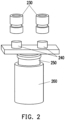
FIG. 2 is a schematic view of an internal structure of a relay body in a relay according to an embodiment of the present disclosure. -
FIG. 3 is a top view of a relay according to an embodiment of the present disclosure. -
FIG. 4 is a sectional view taken along line A-A inFIG. 3 . -
FIG. 5 is a schematic structural view of a base in a relay according to an embodiment of the present disclosure. -
FIG. 6a andFIG. 6b are schematic structural views of a buffer member in a relay according to an embodiment of the present disclosure. -
FIG. 7 is a schematic structural view of a support member in a relay according to an embodiment of the present disclosure. -
FIG. 8a andFIG. 8b are schematic structural views of a sound absorbing element in a relay according to an embodiment of the present disclosure. - The technical solutions in the exemplary embodiments of the disclosure will be described clearly and explicitly in conjunction with the drawings in the exemplary embodiments of the disclosure. The description proposed herein is just the exemplary embodiments for the purpose of illustrations only, not intended to limit the scope of the disclosure, so it should be understood that and various modifications and variations could be made thereto without departing from the scope of the disclosure.
- In the description of the present disclosure, unless otherwise specifically defined and limited, the terms "first", "second" and the like are only used for illustrative purposes and are not to be construed as expressing or implying a relative importance. The term "plurality" is two or more. The term "and/or" includes any and all combinations of one or more of the associated listed items.
- In particular, a reference to "the" object or "a" and "an" object is intended to denote also one of a possible plurality of such objects. Unless otherwise defined or described, the terms "connect", "fix" should be broadly interpreted, for example, the term "connect" can be "fixedly connect", "detachably connect", "integrally connect", "electrically connect" or "signal connect". The term "connect" also can be "directly connect" or "indirectly connect via a medium". For the persons skilled in the art, the specific meanings of the abovementioned terms in the present disclosure can be understood according to the specific situation.
- Further, in the description of the present disclosure, it should be understood that spatially relative terms, such as "above", "below" "inside", "outside" and the like, are described based on orientations illustrated in the figures, but are not intended to limit the exemplary embodiments of the present disclosure.
- In the context, it should also be understood that when an element or features is provided "outside" or "inside" of another element(s), it can be directly provided "outside" or "inside" of the other element, or be indirectly provided "outside" or "inside" of the another element(s) by an intermediate element.
- In the first aspect, as shown in
FIG. 1 andFIG. 2 , an embodiment of the present disclosure provides a relay, which includes arelay body 200 and abuffer assembly 300. - The
relay body 200 includes a housing, astationary contact 230, amovable contact 240 and a coil assembly located inside the housing. The coil assembly may drive themovable contact 240 to move toward or away from thestationary contact 230 to make themovable contact 240 to contact or disconnect from thestationary contact 230. For example, the housing includes anupper housing 210 and alower housing 220, and theupper housing 210 and thelower housing 220 are engaged. The coil assembly includes aniron core 250 and acoil 260 for driving themovable contact 240 to move. The electromagnetic force generated by theiron core 250 and thecoil 260 may drive themovable contact 240 to move, such that themovable contact 240 contacts or disconnects from thestationary contact 230, so as to realize the electromagnetic switching action. For example, after thecoil 260 is energized, theiron core 250 is magnetized to generate a sufficient electromagnetic force, which attracts an armature and drives a reed, such that themovable contact 240 and thestationary contact 230 are closed or separated. That is, the originally closed contact is disconnected, and the originally disconnected contact is closed to realize the input and output of the overall current to the battery pack through the relay. When the relay is opened and closed, since the action of themovable contact 240 drives the relay to vibrate, the relay generates a loud noise. - The housing is fixed through the
base 100. Thebuffer assembly 300 is arranged on thebase 100 and/or outside the housing to buffer the force generated by the action of themovable contact 240. In the relay provided by the embodiment of the present disclosure, abuffer assembly 300 is provided on the base 100 or the outside of the housing of therelay body 200, and thebuffer assembly 300 is located at the connection between the relay and other devices such as a power distribution box or a battery pack, which serves a buffering function and reduces the vibration of the relay, and the structural design of therelay body 200 does not need to be changed. Therefore, the relay provided by the embodiment of the present disclosure adopts a simple structure, and the noise may be reduced at a low cost. - In some embodiments, the
buffer assembly 300 includes abuffer member 310. It can be understood that the function of the buffer member is to provide a buffer function for the relay, therefore, any structure that can achieve the above functions may be used as the buffer member in this embodiment. For example, the buffer is an elastic pad, which is adhered to the base and is located on a surface of the base in contact with other electrical devices. Alternatively, the elastic pad is adhered to the housing of the relay body and is located on an outer surface of the housing in contact with other electrical devices. Alternatively, the buffer member is in a shape or structure that can function as a buffer. Thebuffer member 310 buffers and attenuates the vibration of the relay, reduces the noise of the relay, and improves the user experience. - In some embodiments, the
buffer member 310 is made of elastic material, such as rubber, etc., but is not limited thereto. - In some embodiments, the
base 100 is provided with a fixinghole 101 penetrating thebase 100. Thebuffer member 310 is a cylindrical structure, and thebuffer member 310 is arranged in the fixinghole 101. - In a possible implementation, the
cylindrical buffer member 310 is arranged in the fixinghole 101 of thebase 100, and the axis of thebuffer member 310 is parallel to the axis of the fixinghole 101. Thebase 100 is connected and fixed with other electrical devices through the fixinghole 101, and thebuffer member 310 may buffer and attenuate the vibration of thebase 100, thereby reducing the noise generated by the vibration of the relay. Exemplarily, thebuffer member 310 is engaged in the fixinghole 101, for example, thebuffer member 310 is in an interference fit with thebase 100, or thebuffer member 310 is engaged with the base 100 through a snap. - In some embodiments, the
buffer member 310 at least partially protrudes from the first surface, and the first surface is a surface on one side of the base 100 facing away from therelay body 200. - In the relay, referring to
FIG. 3 andFIG. 4, FIG. 4 is a sectional view ofFIG. 3 , the sectional line includes a section AO and a section OA with an obtuse angle, and a point O is located on the axis of the fixinghole 101 and thebuffer member 310. The fixinghole 101 coincides with the axis of thebuffer member 310. Thebase 100 includes a first surface and a second surface opposite to each other, the first surface of thebase 100 is used for contacting other devices, and therelay body 200 is arranged on the second surface of thebase 100. Thebase 100 is provided with the fixinghole 101, thebuffer member 310 is arranged in the fixinghole 101, and thebuffer member 310 at least partially protrudes from the first surface. That is, when thebase 100 is in contact with other devices, the part of thebuffer member 310 protruding from the first surface of thebase 100 is in direct contact with the surfaces of other devices and may serve a buffering function. In the relay provided by an embodiment of the present disclosure, thebuffer assembly 300 is provided on thebase 100, and thebuffer assembly 300 is located at the connection between the base 100 and other devices, such as a power distribution box or a battery pack, to serve a buffering function, reduce the vibration of the relay, and the structural design of therelay body 200 does not need to be changed. Therefore, the relay provided by the embodiment of the present disclosure adopts a simple structure, and the noise may be reduced at a low cost. - In a possible implementation, there is a notch on the side wall of the fixing
hole 101, as shown inFIG. 3 . The notch has a width L, the diameter of thebuffer member 310 is D2, and L< D2. Exemplarily, thebuffer member 310 may be inserted into the fixinghole 101 from the notch on the side wall of the fixinghole 101. Since the width L of the notch is smaller than the diameter D2 of thebuffer member 310, it is possible to prevent thebuffer member 310 from sliding out of the notch. Continuing to refer toFIG. 4 in conjunction withFIG. 5 , an engagingportion 110 is provided on the side wall of the fixinghole 101. The engagingportion 110 extends along the circumferential direction of the fixinghole 101, and thebuffer member 310 is provided with a slot that cooperates with the engagingportion 110 to prevent thebuffer member 310 from shifting. Asupport member 320 is used to provide rigid support for thebuffer member 310. - In some embodiments, referring to
FIG. 4 , along the direction of an axis OO' of thebuffer member 310, thebuffer member 310 includes afirst end portion 311, a connectingsegment 312 and asecond end portion 313. Exemplarily, the axis OO' of thebuffer member 310 is perpendicular to the first surface of thebase 100. A plurality ofprotrusions 314 are provided on one side of thefirst end portion 311 facing away from the connectingsegment 312, and the plurality ofprotrusions 314 are distributed at intervals around the axis of thebuffer member 310. And/or, a plurality ofprotrusions 314 are provided on one side of thesecond end portion 313 facing away from the connectingsegment 312, and the plurality ofprotrusions 314 are distributed at intervals around the axis of thebuffer member 310. - It should be noted that, "a plurality" can be understood as two or more. Here, "and/or" includes three solutions as follow. A plurality of
protrusions 314 are provided on one side of thefirst end portion 311 facing away from the connectingsegment 312, the plurality ofprotrusions 314 are distributed at intervals around the axis of thebuffer member 310, and thesecond end portion 313 is not provided with protrusions. Alternatively, thefirst end portion 311 is not provided with protrusions, and a plurality ofprotrusions 314 are provided on one side of thesecond end portion 313 facing away from the connectingsegment 312, and the plurality ofprotrusions 314 are distributed at intervals around the axis of thebuffer member 310. Alternatively, the plurality ofprotrusions 314 are provided on one side of thefirst end portion 311 facing away from the connectingsegment 312, the plurality ofprotrusions 314 are distributed at intervals around the axis of thebuffer member 310, the plurality ofprotrusions 314 are provided on one side of thesecond end portion 313 facing away from the connectingsegment 312, and the plurality ofprotrusions 314 are distributed at intervals around the axis of thebuffer member 310. - In a possible implementation, referring to
FIG. 6a andFIG. 6b , thebuffer member 310 is substantially a cylindrical structure, and thebuffer member 310 is engaged with the fixinghole 101. Thebuffer member 310 includes afirst end portion 311, a connectingsegment 312 and asecond end portion 313. The outer diameter of the connectingsegment 312 is smaller than the outer diameter of thefirst end portion 311, and the outer diameter of the connectingsegment 312 is smaller than the outer diameter of thesecond end portion 313. Therefore, thefirst end portion 311, the connectingsegment 312 and thesecond end portion 313 form a concave slot to be engaged with the engagingportion 110 on the side wall of the fixinghole 101. A plurality ofprotrusions 314 are provided on one side of thefirst end portion 311 facing away from the connectingsegment 312. For example, there are eightprotrusions 314 inFIG. 6a , there are sixprotrusions 314 inFIG. 6b , the plurality ofprotrusions 314 are annularly distributed along the circumference of thefirst end portion 311, and thesupport member 320 is in direct contact with theprotrusions 314. Further referring toFIG. 6a andFIG. 6b , a plurality ofprotrusions 314 are provided on one side of thesecond end portion 313 facing away from the connectingsegment 312, the plurality ofprotrusions 314 are annularly distributed along the circumference of thesecond end portion 313, and theprotrusions 314 on thesecond end portion 313 are in direct contact with other devices. It should be noted that, thebuffer member 310 achieves the buffering effect through the deformation of theprotrusions 314, rather than through the contact between the entire end surface of thebuffer member 310 with other devices. In this manner, it is possible to prevent the risk of cracking of the end surface of thebuffer member 310, thereby achieving the effect of increasing the service life. - In some embodiments, the
buffer assembly 300 further includes asupport member 320. Thebuffer member 310 is internally provided with a sleeve hole for coupling with thesupport member 320, and the axis of the sleeve hole is parallel to the axis of thebuffer member 310. - In a possible implementation, continuing to refer to
FIG. 3 andFIG. 4 , thesupport member 320 is inserted into the sleeve hole inside thebuffer member 310, and thesupport member 320 may provide support and guidance for thebuffer member 310. Exemplarily, thesupport member 320 is in an interference fit with thebuffer member 310. - In some embodiments, a plurality of protruding
strips 315 are arranged along the axial direction of the sleeve hole on the side wall of the sleeve hole, and the extending direction of the protruding strips 315 is parallel to the axial direction of thebuffer member 310. - In a possible implementation, further referring to
FIG. 6a andFIG. 6b , thebuffer member 310 has a sleeve hole matched with thesupport member 320, a plurality of protrudingstrips 315 are arranged along the circumference of thebuffer member 310 on the inner wall of thebuffer member 310, and the plurality of protrudingstrips 315 are arranged at intervals. An avoidingslot 316 is formed between two adjacent protrudingstrips 315, that is, the slot wall of the avoidingslot 316 is the protruding strips 315 on both sides. The opening of the avoidingslot 316 faces the axis of thebuffer member 310. Exemplarily, the cross section of the avoidingslot 316 is U-shaped or V-shaped. The protruding strips 315 on thebuffer member 310 may relieve the frictional force when thebuffer member 310 is assembled with thesupport member 320. When thesupport member 320 is inserted into the sleeve hole, thesupport member 320 contacts the protrudingstrip 315, and thesupport member 320 does not contact the part corresponding to the avoidingslot 316, thereby reducing the frictional force. In the meantime, the protrudingstrips 315 may increase the rigidity of thebuffer member 310 to a certain extent, and the surface on one side of the protrudingstrips 315 facing the center of the support hole is in direct contact with thesupport member 320. When thebuffer member 310 is squeezed, the structures of the slot and the protrudingstrips 315 of thebuffer member 310 are deformed, that is, through structural deformation, thebuffer member 310 may effectively prevent the risk of cracking of thebuffer member 310 caused by deformation, so as to increase the service life. - In some embodiments, the
support member 320 includes acover plate portion 321 and aguide portion 322. Theguide portion 322 is sleeved with thebuffer member 310, and thecover plate portion 321 is in contact with thefirst end portion 311. Thesupport member 320 has a connection hole penetrating through thecover plate portion 321 and theguide portion 322, and the axial direction of the connection hole is parallel to the axial direction of the sleeve hole. Exemplarily, the axial direction of the connection hole coincides with the axial direction of the sleeve hole. - In a possible implementation, referring to
FIG. 7 , thesupport member 320 includes acover plate portion 321 and aguide portion 322, and thecover plate portion 321 and theguide portion 322 form a T-shaped structure. Referring toFIG. 4 ,FIG. 6a andFIG. 6b , theguide portion 322 is inserted into the sleeve hole in thebuffer member 310 and is in direct contact with the protrudingstrip 315 of thebuffer member 310. The size of thecover plate portion 321 is larger than the size of the sleeve hole. When theguide portion 322 is inserted into the sleeve hole, thecover plate portion 321 remains outside the sleeve hole, and a surface in thecover plate portion 321 facing one side of the first surface of thebase 100 is in direct contact with theprotrusions 314 on thebuffer member 310. Thesupport member 320 may provide a supporting force for thebuffer member 310 while preventing thebuffer member 310 from deforming too much, thus protecting thebuffer member 310. In addition, thesupport member 320 has a connection hole therein for matching with the connection member. The connection member penetrates through the connection hole to realize the connection between the relay and other devices. - In some embodiments, the
support member 320 includes a steel sleeve, and the support strength is relatively high. Thesupport member 320 may also include a copper sleeve, an aluminum sleeve, etc., but is not limited thereto. - In some embodiments, the
base 100 has a configuration area for configuring therelay body 200, and the fixinghole 101 is located outside the configuration area. - In a possible implementation, continuing to refer to
FIG. 4 , therelay body 200 is arranged in the middle area of thebase 100, and the fixinghole 101 is provided in the area of thebase 100 near the edge. In this way, neither the configuration of therelay body 200 nor the fixation of thebase 100 is affected. - In some embodiments, there are a plurality of fixing
holes 101, and the plurality of fixingholes 101 are distributed at intervals around the configuration area. Abuffer assembly 300 is arranged in at least one fixinghole 101. - It should be noted that when the
buffer assembly 300 is arranged in at least one fixinghole 101, it can be understood that some of the fixingholes 101 are provided with thebuffer assembly 300, and some of the fixingholes 101 are not provided with thebuffer assembly 300, and the number of the fixing holes provided with thebuffer assembly 300 is greater than 1; or, all of the fixingholes 101 are provided with thebuffer assembly 300. - In a possible implementation, continuing to refer to
FIG. 1 andFIG. 3 , there are two fixingholes 101 on thebase 100, and each of the fixing holes 101 is provided with abuffer assembly 300. In addition, thebase 100 may be approximately regarded as a rectangle, and the two fixingholes 101 are arranged along the diagonal of the rectangle. - In order to further reduce noise, in some embodiments, a
sound absorbing element 400 is disposed between therelay body 200 and the base 100 to reduce the noise between therelay body 200 and thebase 100. - In some embodiments, the
sound absorbing element 400 includes at least one of sound dampening cotton or sound absorbing cotton or sound insulating cotton. - It should be noted that, the sound absorbing cotton is a roll-like/sheet-like material processed from a single or multiple different fibers through various processes. Two-component sound absorbing cotton is commonly adopted, and polyester sound absorbing cotton is one of them. As shown in
FIG. 8a andFIG. 8b , the sound absorbing cotton adopted in this embodiment is a sheet-like structure. - The sound absorbing cotton is a man-made inorganic fiber, which uses quartz sand, limestone, dolomite and other natural ores as the main raw materials, and is combined with some soda ash, borax and other chemical raw materials to be melted into glass. The sound absorbing cotton has high sound absorption rate and good performance in sound insulation.
- The sound insulation cotton is a fiber porous sound insulation material, such as polyester fiber cotton sound insulation cotton, centrifugal glass wool, rock wool, mineral wool, plant fiber coating, etc. The sound insulation mechanism of sound insulation cotton is that there are a large number of tiny connected pores inside the material, and sound waves can pass through along these pores to enter the material. The friction between the sound waves and the material converts the sound energy into heat energy. The sound insulation characteristic of porous sound insulation materials is that the sound insulation coefficient gradually increases with the increase of frequency, which means that the low frequency absorption is not as good as the high frequency absorption. For example, the vibration of objects generates sound, the sound waves are transmitted in the air, and the sound insulation cotton has a multi-fiber structure. When the sound waves pass through the cotton, they are reflected, superimposed, and collided through countless fibers. In this way, the sound wave energy is converted into heat energy, the intensity of sound wave is weakened, and the sound disappears.
- In some embodiments, the relay further includes a
first connector 500, and thefirst connector 500 penetrates through thebase 100, thesound absorbing element 400 and therelay body 200 in sequence. - In a possible implementation, referring to
FIG. 1 ,FIG. 3 andFIG. 4 in combination withFIG. 8a , thebase 100 and therelay body 200 are connected through thefirst connector 500. Thesound absorbing element 400 is located between the base 100 and therelay body 200. In order to fix thesound absorbing element 400 as well, thefirst connector 500 penetrates through thebase 100, thesound absorbing element 400 and therelay body 200 in sequence. For example, thefirst connector 500 is a threaded pillar. - In a second aspect, an embodiment of the present disclosure further provides a battery power distribution box, including a frame and the relay described in any one of the embodiments of the first aspect, and the relay is arranged on the frame. The
buffer assembly 300 in the relay is in contact with the frame. - In a possible implementation, the relay is arranged on the frame through a second connector, for example, the second connector penetrates through the connection hole of the
support member 320, so that the relay and the frame are fixed relative to each other. - In a third aspect, an embodiment of the present disclosure further provides a battery pack, including a box body and the relay described in any one of the embodiments of the first aspect. The relay is arranged in the box body, and the
buffer assembly 300 is in contact with the box body. - In a possible implementation, the relay is arranged on the box body through a third connector, for example, the third connector penetrates through the connection hole of the
support member 320, so that the relay and the box body are fixed relative to each other. - In a fourth aspect, an embodiment of the present disclosure further provides a battery pack, including a box body and the relay described in any one of the embodiments of the first aspect. The battery distribution box is arranged in the box body.
- In a possible implementation, the relay is arranged in the battery distribution box, and the battery distribution box is arranged in the box body. The relay is arranged on the frame through the second connector. For example, the second connector penetrates through the connection hole of the
support member 320, so that the relay and the frame are fixed relative to each other. - Therefore, in the relay provided by the embodiment of the present disclosure, the generated noise may be reduced by arranging the
buffer assembly 300 on thebase 100, and thesound absorbing element 400 is arranged at the bottom of therelay body 200, that is, between therelay body 200 and the base 100 to absorb the noise, so as to reduce the noise generated by the relay and improve the user experience. - Other embodiments of the disclosure will be apparent to those skilled in the art from consideration of the specification and practice of the disclosure disclosed herein. The disclosure is intended to cover any variations, uses or adaptations of the disclosure. These variations, uses, or adaptations follow the general principles of the disclosure and include common general knowledge or conventional technical means in the art that are not disclosed in the present disclosure. The specification and embodiments are illustrative.
Claims (16)
- A relay, comprising: a relay body (200) and a buffer assembly (300);wherein the relay body (200) comprises a housing and a stationary contact (230), a movable contact (240) and a coil assembly inside the housing, the coil assembly is able to drive the movable contact (240) to move toward or away from the stationary contact (230), such that the movable contact (240) is brought into contact with or disconnected from the stationary contact (230);the housing is fixed through a base (100), and the buffer assembly (300) is arranged on the base (100), and/or mounted on an outside of the housing, and configured to buffer a force generated by an action of the movable contact (240).
- The relay according to claim 1, wherein the buffer assembly (300) comprises a buffer member (310);
the base (100) is provided with a fixing hole (101) penetrating the base (100), the buffer member (310) is a cylindrical structure, and the buffer member (310) is arranged in the fixing hole (101). - The relay according to claim 2, wherein the buffer member (310) at least partially protrudes from a first surface, and the first surface is a surface on one side of the base (100) facing away from the relay body (200).
- The relay according to claim 2, wherein along an axial direction of the buffer member (310), the buffer member (310) comprises a first end portion (311), a connecting segment (312) and a second end portion (313);a plurality of protrusions (314) are provided on one side of the first end portion (311) facing away from the connecting segment (312), and the plurality of protrusions (314) are distributed at intervals around an axis of the buffer member (310); and/or,the plurality of protrusions (314) are provided on one side of the second end portion (313) facing away from the connecting segment (312), and the plurality of protrusions (314) are distributed at intervals around the axis of the buffer member (310).
- The relay according to claim 4, wherein the buffer assembly (300) further comprises a support member (320), the buffer member (310) is internally provided with a sleeve hole for coupling with the support member (320), and an axis of the sleeve hole is parallel to the axis of the buffer member (310).
- The relay according to claim 5, wherein a plurality of protruding strips (315) are arranged along an axial direction of the sleeve hole on a side wall of the sleeve hole, and an extending direction of the protruding strips (315) is parallel to the axial direction of the buffer member (310).
- The relay according to claim 5, wherein the support member (320) comprises a cover plate portion (321) and a guide portion (322), the guide portion (322) is sleeved with the buffer member (310), and the cover plate portion (321) is in contact with the first end portion (311);
the support member (320) has a connection hole penetrating through the cover plate portion (321) and the guide portion (322), and an axial direction of the connection hole is parallel to an axial direction of the sleeve hole. - The relay according to any one of claims 2-7, wherein the base (100) has a configuration area for configuring the relay body (200), and the fixing hole (101) is located outside the configuration area.
- The relay according to claim 8, wherein the fixing hole (101) is in plurality, and the plurality of the fixing holes (101) are distributed at intervals around the configuration area; and
at least one of the fixing holes (101) is provided with the buffer assembly. - The relay according to claim 9, wherein the buffer assembly corresponds to the fixing holes (101) one by one.
- The relay according to any one of claims 1-7, wherein a sound absorbing element (400) is arranged between the relay body (200) and the base (100).
- The relay according to claim 11, wherein the sound absorbing element (400) comprises at least one of a sound dampening cotton or a sound absorbing cotton or a sound insulating cotton.
- The relay according to claim 12, wherein the relay further comprises a first connector (500), and the first connector (500) penetrates through the base (100), the sound absorbing element (400) and the relay body (200) in sequence.
- A battery power distribution box, comprising a frame and the relay as claimed in any one of claims 1-13, wherein the relay is arranged on the frame;
wherein the buffer assembly in the relay is in contact with the frame. - A battery pack, comprising a box body and the relay as claimed in any one of claims 1-13;
wherein the relay is arranged in the box body, and the buffer assembly is in contact with the box body. - A battery pack, comprising a box body and the battery power distribution box as claimed in claim 14;
wherein the battery distribution box is arranged in the box body.
Applications Claiming Priority (1)
| Application Number | Priority Date | Filing Date | Title |
|---|---|---|---|
| CN202210263968.8A CN114496658A (en) | 2022-03-17 | 2022-03-17 | Relay, battery distribution box and battery package |
Publications (1)
| Publication Number | Publication Date |
|---|---|
| EP4246550A1 true EP4246550A1 (en) | 2023-09-20 |
Family
ID=81485666
Family Applications (1)
| Application Number | Title | Priority Date | Filing Date |
|---|---|---|---|
| EP22175740.4A Withdrawn EP4246550A1 (en) | 2022-03-17 | 2022-05-27 | Relay, battery distribution box and battery pack |
Country Status (3)
| Country | Link |
|---|---|
| US (1) | US12080498B2 (en) |
| EP (1) | EP4246550A1 (en) |
| CN (1) | CN114496658A (en) |
Families Citing this family (2)
| Publication number | Priority date | Publication date | Assignee | Title |
|---|---|---|---|---|
| CN118156089B (en) * | 2024-05-11 | 2024-08-06 | 武汉嘉晨电子技术股份有限公司 | Battery pack circuit breaking unit and battery pack |
| CN120784133B (en) * | 2025-09-08 | 2026-03-03 | 宁德时代新能源科技股份有限公司 | Battery device and electric equipment |
Citations (9)
| Publication number | Priority date | Publication date | Assignee | Title |
|---|---|---|---|---|
| JPH06196070A (en) * | 1992-12-24 | 1994-07-15 | Nec Corp | Electromagnetic relay |
| JPH10223111A (en) * | 1997-02-03 | 1998-08-21 | Honda Motor Co Ltd | Outboard relay |
| JP2001165241A (en) * | 1999-12-10 | 2001-06-19 | Kitagawa Ind Co Ltd | Vibration isolation support |
| JP3740870B2 (en) * | 1998-11-25 | 2006-02-01 | 松下電工株式会社 | Silent device for equipment using relay |
| US20080068116A1 (en) * | 2006-09-19 | 2008-03-20 | Panasonic Ev Energy Co., Ltd. | Battery pack |
| JP2009268548A (en) * | 2008-04-30 | 2009-11-19 | Newgin Co Ltd | Control device of game machine |
| JP4669267B2 (en) * | 2004-11-26 | 2011-04-13 | 大塚ポリテック株式会社 | Mounting structure of electromagnetic relay |
| US8653922B2 (en) * | 2012-02-28 | 2014-02-18 | Radiall | Electromechanical relay housing, relay, switching assembly and electromagnetic relay support assembly |
| CN106206165A (en) * | 2016-09-07 | 2016-12-07 | 泉州圆创机械技术开发有限公司 | A kind of Shockproof relay |
Family Cites Families (7)
| Publication number | Priority date | Publication date | Assignee | Title |
|---|---|---|---|---|
| JPH0495325A (en) * | 1990-07-31 | 1992-03-27 | Mitsubishi Electric Corp | Electromagnetic switch device |
| DE19813530A1 (en) * | 1998-03-26 | 1999-10-07 | Siemens Ag | Sound-reduced relay |
| JP4190379B2 (en) * | 2003-09-12 | 2008-12-03 | 富士通コンポーネント株式会社 | Combined electromagnetic relay |
| JP6025414B2 (en) * | 2011-09-30 | 2016-11-16 | 富士通コンポーネント株式会社 | Electromagnetic relay |
| JP6726080B2 (en) * | 2016-10-20 | 2020-07-22 | 富士通コンポーネント株式会社 | Electromagnetic relay |
| US10825631B2 (en) * | 2018-07-23 | 2020-11-03 | Te Connectivity Corporation | Solenoid assembly with decreased release time |
| US11764010B2 (en) * | 2018-10-19 | 2023-09-19 | Te Connectivity Solutions Gmbh | Contactor with arc suppressor |
-
2022
- 2022-03-17 CN CN202210263968.8A patent/CN114496658A/en active Pending
- 2022-05-27 EP EP22175740.4A patent/EP4246550A1/en not_active Withdrawn
- 2022-05-29 US US17/827,775 patent/US12080498B2/en active Active
Patent Citations (9)
| Publication number | Priority date | Publication date | Assignee | Title |
|---|---|---|---|---|
| JPH06196070A (en) * | 1992-12-24 | 1994-07-15 | Nec Corp | Electromagnetic relay |
| JPH10223111A (en) * | 1997-02-03 | 1998-08-21 | Honda Motor Co Ltd | Outboard relay |
| JP3740870B2 (en) * | 1998-11-25 | 2006-02-01 | 松下電工株式会社 | Silent device for equipment using relay |
| JP2001165241A (en) * | 1999-12-10 | 2001-06-19 | Kitagawa Ind Co Ltd | Vibration isolation support |
| JP4669267B2 (en) * | 2004-11-26 | 2011-04-13 | 大塚ポリテック株式会社 | Mounting structure of electromagnetic relay |
| US20080068116A1 (en) * | 2006-09-19 | 2008-03-20 | Panasonic Ev Energy Co., Ltd. | Battery pack |
| JP2009268548A (en) * | 2008-04-30 | 2009-11-19 | Newgin Co Ltd | Control device of game machine |
| US8653922B2 (en) * | 2012-02-28 | 2014-02-18 | Radiall | Electromechanical relay housing, relay, switching assembly and electromagnetic relay support assembly |
| CN106206165A (en) * | 2016-09-07 | 2016-12-07 | 泉州圆创机械技术开发有限公司 | A kind of Shockproof relay |
Also Published As
| Publication number | Publication date |
|---|---|
| US20230298838A1 (en) | 2023-09-21 |
| US12080498B2 (en) | 2024-09-03 |
| CN114496658A (en) | 2022-05-13 |
Similar Documents
| Publication | Publication Date | Title |
|---|---|---|
| US12080498B2 (en) | Relay, battery distribution box and battery pack | |
| EP3089189B1 (en) | Contact device | |
| US8102228B2 (en) | Core securing member and its structure | |
| US8558648B2 (en) | Electromagnetic switching apparatus | |
| CN108615654A (en) | A kind of memorial alloy and inertial confinement multi-channel switch | |
| CN113708588B (en) | Vibration motor | |
| JP2023163729A (en) | Vibration actuators and electrical equipment | |
| CN216902699U (en) | Relay, battery distribution box and battery package | |
| CN108565143A (en) | A kind of electromagnetism and centrifugation constrain multi-channel switch | |
| CN108615653A (en) | A kind of hot melt alloy and inertial confinement multi-channel switch | |
| US20210344089A1 (en) | Protection assembly of battery module and battery module | |
| JP5447594B2 (en) | Magnetic contactor | |
| US6225714B1 (en) | Electric motor, especially a permanently excited direct current motor | |
| WO2021040405A1 (en) | Vehicle lp fuse fixing terminal | |
| CN220085923U (en) | vacuum contactor | |
| CN206850651U (en) | Linear vibration motor and electronic equipment | |
| CN215420043U (en) | Energy collecting device | |
| CN220435319U (en) | Enclosed contactor loading device | |
| CN216624112U (en) | Safe insulating type relay | |
| CN221928472U (en) | Batteries and electrical devices | |
| CN212570902U (en) | Release and circuit breaker | |
| CN220673078U (en) | Mounting bracket of electric component and mobile power station | |
| CN220231988U (en) | Detection device | |
| CN223296741U (en) | Signal sampling structure of circuit breaker | |
| CN210778415U (en) | Aluminum alloy shell of high-frequency relay for communication base station |
Legal Events
| Date | Code | Title | Description |
|---|---|---|---|
| PUAI | Public reference made under article 153(3) epc to a published international application that has entered the european phase |
Free format text: ORIGINAL CODE: 0009012 |
|
| STAA | Information on the status of an ep patent application or granted ep patent |
Free format text: STATUS: REQUEST FOR EXAMINATION WAS MADE |
|
| 17P | Request for examination filed |
Effective date: 20220527 |
|
| AK | Designated contracting states |
Kind code of ref document: A1 Designated state(s): AL AT BE BG CH CY CZ DE DK EE ES FI FR GB GR HR HU IE IS IT LI LT LU LV MC MK MT NL NO PL PT RO RS SE SI SK SM TR |
|
| STAA | Information on the status of an ep patent application or granted ep patent |
Free format text: STATUS: EXAMINATION IS IN PROGRESS |
|
| 17Q | First examination report despatched |
Effective date: 20241022 |
|
| STAA | Information on the status of an ep patent application or granted ep patent |
Free format text: STATUS: THE APPLICATION HAS BEEN WITHDRAWN |
|
| 18W | Application withdrawn |
Effective date: 20250207 |