EP4246371A1 - Activity recognition method, display method, and electronic device - Google Patents
Activity recognition method, display method, and electronic device Download PDFInfo
- Publication number
- EP4246371A1 EP4246371A1 EP21902307.4A EP21902307A EP4246371A1 EP 4246371 A1 EP4246371 A1 EP 4246371A1 EP 21902307 A EP21902307 A EP 21902307A EP 4246371 A1 EP4246371 A1 EP 4246371A1
- Authority
- EP
- European Patent Office
- Prior art keywords
- feature data
- electronic device
- person
- feature
- dimensional convolutional
- Prior art date
- Legal status (The legal status is an assumption and is not a legal conclusion. Google has not performed a legal analysis and makes no representation as to the accuracy of the status listed.)
- Pending
Links
Images











Classifications
-
- G—PHYSICS
- G06—COMPUTING OR CALCULATING; COUNTING
- G06F—ELECTRIC DIGITAL DATA PROCESSING
- G06F18/00—Pattern recognition
- G06F18/20—Analysing
- G06F18/24—Classification techniques
- G06F18/241—Classification techniques relating to the classification model, e.g. parametric or non-parametric approaches
- G06F18/2413—Classification techniques relating to the classification model, e.g. parametric or non-parametric approaches based on distances to training or reference patterns
-
- G—PHYSICS
- G01—MEASURING; TESTING
- G01C—MEASURING DISTANCES, LEVELS OR BEARINGS; SURVEYING; NAVIGATION; GYROSCOPIC INSTRUMENTS; PHOTOGRAMMETRY OR VIDEOGRAMMETRY
- G01C21/00—Navigation; Navigational instruments not provided for in groups G01C1/00 - G01C19/00
- G01C21/005—Navigation; Navigational instruments not provided for in groups G01C1/00 - G01C19/00 with correlation of navigation data from several sources, e.g. map or contour matching
-
- G—PHYSICS
- G06—COMPUTING OR CALCULATING; COUNTING
- G06F—ELECTRIC DIGITAL DATA PROCESSING
- G06F3/00—Input arrangements for transferring data to be processed into a form capable of being handled by the computer; Output arrangements for transferring data from processing unit to output unit, e.g. interface arrangements
- G06F3/01—Input arrangements or combined input and output arrangements for interaction between user and computer
- G06F3/048—Interaction techniques based on graphical user interfaces [GUI]
- G06F3/0481—Interaction techniques based on graphical user interfaces [GUI] based on specific properties of the displayed interaction object or a metaphor-based environment, e.g. interaction with desktop elements like windows or icons, or assisted by a cursor's changing behaviour or appearance
- G06F3/04817—Interaction techniques based on graphical user interfaces [GUI] based on specific properties of the displayed interaction object or a metaphor-based environment, e.g. interaction with desktop elements like windows or icons, or assisted by a cursor's changing behaviour or appearance using icons
-
- G—PHYSICS
- G01—MEASURING; TESTING
- G01C—MEASURING DISTANCES, LEVELS OR BEARINGS; SURVEYING; NAVIGATION; GYROSCOPIC INSTRUMENTS; PHOTOGRAMMETRY OR VIDEOGRAMMETRY
- G01C21/00—Navigation; Navigational instruments not provided for in groups G01C1/00 - G01C19/00
- G01C21/10—Navigation; Navigational instruments not provided for in groups G01C1/00 - G01C19/00 by using measurements of speed or acceleration
- G01C21/12—Navigation; Navigational instruments not provided for in groups G01C1/00 - G01C19/00 by using measurements of speed or acceleration executed aboard the object being navigated; Dead reckoning
- G01C21/16—Navigation; Navigational instruments not provided for in groups G01C1/00 - G01C19/00 by using measurements of speed or acceleration executed aboard the object being navigated; Dead reckoning by integrating acceleration or speed, i.e. inertial navigation
- G01C21/165—Navigation; Navigational instruments not provided for in groups G01C1/00 - G01C19/00 by using measurements of speed or acceleration executed aboard the object being navigated; Dead reckoning by integrating acceleration or speed, i.e. inertial navigation combined with non-inertial navigation instruments
-
- G—PHYSICS
- G01—MEASURING; TESTING
- G01C—MEASURING DISTANCES, LEVELS OR BEARINGS; SURVEYING; NAVIGATION; GYROSCOPIC INSTRUMENTS; PHOTOGRAMMETRY OR VIDEOGRAMMETRY
- G01C21/00—Navigation; Navigational instruments not provided for in groups G01C1/00 - G01C19/00
- G01C21/10—Navigation; Navigational instruments not provided for in groups G01C1/00 - G01C19/00 by using measurements of speed or acceleration
- G01C21/12—Navigation; Navigational instruments not provided for in groups G01C1/00 - G01C19/00 by using measurements of speed or acceleration executed aboard the object being navigated; Dead reckoning
- G01C21/16—Navigation; Navigational instruments not provided for in groups G01C1/00 - G01C19/00 by using measurements of speed or acceleration executed aboard the object being navigated; Dead reckoning by integrating acceleration or speed, i.e. inertial navigation
- G01C21/165—Navigation; Navigational instruments not provided for in groups G01C1/00 - G01C19/00 by using measurements of speed or acceleration executed aboard the object being navigated; Dead reckoning by integrating acceleration or speed, i.e. inertial navigation combined with non-inertial navigation instruments
- G01C21/1654—Navigation; Navigational instruments not provided for in groups G01C1/00 - G01C19/00 by using measurements of speed or acceleration executed aboard the object being navigated; Dead reckoning by integrating acceleration or speed, i.e. inertial navigation combined with non-inertial navigation instruments with electromagnetic compass
-
- G—PHYSICS
- G01—MEASURING; TESTING
- G01C—MEASURING DISTANCES, LEVELS OR BEARINGS; SURVEYING; NAVIGATION; GYROSCOPIC INSTRUMENTS; PHOTOGRAMMETRY OR VIDEOGRAMMETRY
- G01C21/00—Navigation; Navigational instruments not provided for in groups G01C1/00 - G01C19/00
- G01C21/20—Instruments for performing navigational calculations
-
- G—PHYSICS
- G06—COMPUTING OR CALCULATING; COUNTING
- G06F—ELECTRIC DIGITAL DATA PROCESSING
- G06F18/00—Pattern recognition
- G06F18/20—Analysing
-
- G—PHYSICS
- G06—COMPUTING OR CALCULATING; COUNTING
- G06F—ELECTRIC DIGITAL DATA PROCESSING
- G06F18/00—Pattern recognition
- G06F18/20—Analysing
- G06F18/24—Classification techniques
- G06F18/241—Classification techniques relating to the classification model, e.g. parametric or non-parametric approaches
- G06F18/2413—Classification techniques relating to the classification model, e.g. parametric or non-parametric approaches based on distances to training or reference patterns
- G06F18/24133—Distances to prototypes
-
- G—PHYSICS
- G06—COMPUTING OR CALCULATING; COUNTING
- G06N—COMPUTING ARRANGEMENTS BASED ON SPECIFIC COMPUTATIONAL MODELS
- G06N3/00—Computing arrangements based on biological models
- G06N3/02—Neural networks
- G06N3/04—Architecture, e.g. interconnection topology
- G06N3/045—Combinations of networks
-
- G—PHYSICS
- G06—COMPUTING OR CALCULATING; COUNTING
- G06N—COMPUTING ARRANGEMENTS BASED ON SPECIFIC COMPUTATIONAL MODELS
- G06N3/00—Computing arrangements based on biological models
- G06N3/02—Neural networks
- G06N3/04—Architecture, e.g. interconnection topology
- G06N3/0464—Convolutional networks [CNN, ConvNet]
-
- G—PHYSICS
- G06—COMPUTING OR CALCULATING; COUNTING
- G06N—COMPUTING ARRANGEMENTS BASED ON SPECIFIC COMPUTATIONAL MODELS
- G06N3/00—Computing arrangements based on biological models
- G06N3/02—Neural networks
- G06N3/08—Learning methods
-
- G—PHYSICS
- G06—COMPUTING OR CALCULATING; COUNTING
- G06N—COMPUTING ARRANGEMENTS BASED ON SPECIFIC COMPUTATIONAL MODELS
- G06N3/00—Computing arrangements based on biological models
- G06N3/02—Neural networks
- G06N3/08—Learning methods
- G06N3/09—Supervised learning
-
- G—PHYSICS
- G06—COMPUTING OR CALCULATING; COUNTING
- G06F—ELECTRIC DIGITAL DATA PROCESSING
- G06F18/00—Pattern recognition
- G06F18/10—Pre-processing; Data cleansing
- G06F18/15—Statistical pre-processing, e.g. techniques for normalisation or restoring missing data
Definitions
- Embodiments of this application relate to the terminal field, and in particular, to an activity recognition (activity recognition, AR) method, a display method, and an electronic device.
- an activity recognition activity recognition, AR
- a mobile terminal can provide, based on a map function, a user with positioning and navigation related services.
- a positioning technology for example, a technology on which a global positioning system (global positioning system, GPS) depends
- a navigation technology for example, a technology on which BeiDou navigation depends
- a mobile terminal can provide, based on the map function, only a service directly associated with a position, for example, positioning, routing, and navigation services. As a result, user experience is poor.
- Embodiments of this application provide an activity recognition method, a display method, and an electronic device, to recognize an activity state of a person and present, in a map interface, an icon representing the activity state of the person.
- an embodiment of this application provides an activity recognition method, including: obtaining a plurality of poses of an electronic device in a time period; obtaining, by using a plurality of one-dimensional convolutional layers, one or more pieces of feature data based on the plurality of poses, where the one or more pieces of feature data indicate different types of information of a person holding the electronic device in the time period, and a type of information indicated by each piece of feature data is a motion state of the person, an action of the person, or a tool carrying the person; and controlling the electronic device to display, as an icon, the types of the information indicated by the one or more pieces of feature data.
- the method is used to recognize the activity state of the person holding the electronic device.
- the activity state of the person holding the electronic device can be represented by at least one type of information in the motion state of the person, the action of the person, or the tool carrying the person.
- the motion state of the person is a state of the person relative to a reference system when the person performs mechanical motion.
- the motion state of the person includes standstill, walking, running, and the like.
- the action of the person includes standing, sitting, squatting, lying, and the like.
- the tool carrying the person includes a vehicle (for example, in-vehicle, and a high-speed railway), a straight ladder, an escalator, and the like taken by the person.
- the pose of the electronic device can reflect the activity state of the person holding the electronic device.
- the electronic device obtains the plurality of poses of the electronic device in a time period, and then extracts the one or more pieces of feature data from the plurality of poses by using an activity recognition (activity recognition, AR) module.
- the one or more pieces of feature data indicate the different types of information of the person holding the electronic device.
- the electronic device controls the electronic device to display, on the icon, the types of the information indicated by the one or more pieces of feature data.
- the "time period" may be preset, and the time period is, for example, 5 seconds (s).
- the AR module performs feature extraction on the plurality of poses by using the plurality of one-dimensional convolutional layers, to obtain the one or more pieces of feature data.
- feature extraction is performed by using the plurality of one-dimensional convolutional layers. This can not only break, during feature extraction model training, a limit of a feature depending on only one dimension of the motion state of the person, so that an obtained feature extraction model has high scalability, but also improve accuracy of the recognized activity state of the person because the feature extraction model obtained through training can recognize the activity state of the person from a plurality of dimensions.
- the electronic device in this embodiment of this application can adaptively present the activity state of the person in real time. This can optimize visual effect of the electronic device and improve use experience.
- the obtaining, by using a plurality of one-dimensional convolutional layers, one or more pieces of feature data based on the plurality of poses includes: obtaining a feature data group based on the plurality of poses by using the plurality of one-dimensional convolutional layers; and obtaining the one or more pieces of feature data from the feature data group.
- the electronic device can perform feature extraction on the plurality of poses by using the plurality of one-dimensional convolutional layers, to obtain the feature data group for representing the activity state of the person. Then, the electronic device can extract, from the feature data group, feature data for representing each specific type, to obtain a specific activity of the person. This can recognize the activity state of the person from the plurality of dimensions, and improve accuracy of the recognized activity state of the person.
- the obtaining a feature data group based on the plurality of poses by using the plurality of one-dimensional convolutional layers includes: performing feature extraction on the plurality of poses by using m one-dimensional convolutional layers in serial combination in a first feature extraction framework, to obtain an initial feature data group; and performing feature extraction on the initial feature data group by using n backbone backbone models in serial combination in a second feature extraction framework, to obtain the feature data group, where each of the n backbone models includes at least two one-dimensional convolutional layers in parallel combination; and m and n each are a positive integer.
- the AR module includes the first feature extraction framework and the second feature extraction framework.
- a one-dimensional convolutional layer in each of the first feature extraction framework and the second feature extraction framework performs feature extraction, and different one-dimensional convolutional layers can extract different types of feature data. It can be learned that in this embodiment of this application, the AR module performs feature extraction on the plurality of poses by using the stacked one-dimensional convolutional layers. This can not only extract a plurality of types of feature data groups of the person, but also have more accurate extracted features for activity recognition after feature extraction is performed by using the plurality of one-dimensional convolutional layers.
- the performing feature extraction on the plurality of poses by using m one-dimensional convolutional layers in serial combination in a first feature extraction framework includes: performing feature extraction on a first initial feature data group by using an i th one-dimensional convolutional layer in the m one-dimensional convolutional layers, to obtain a second initial feature data group, where the first initial feature data group is a feature data group obtained by an (i-1) th one-dimensional convolutional layer in the m one-dimensional convolutional layers based on the plurality of poses, and i is greater than or equal to 2 and less than or equal to m.
- the first feature extraction framework can obtain a plurality of types of feature data groups from the plurality of poses of the electronic device through serial feature extraction on the plurality of poses by using the plurality of one-dimensional convolutional layers.
- the plurality of types of feature data groups are for representing the activity state of the person.
- quantities of channels of the one-dimensional convolutional layers in the first feature extraction framework may increase sequentially based on a data flow direction.
- all or some of quantities of channels of the one-dimensional convolutional layers in the first feature extraction framework may be the same.
- quantities of channels of the one-dimensional convolutional layers in the first feature extraction framework may decrease sequentially.
- the at least two one-dimensional convolutional layers in parallel combination in each backbone model have different values of cores.
- a one-dimensional convolutional layer includes a kernel (kernel, k), and a value of k indicates a quantity of consecutive data in a plurality of pieces of input data used in each convolution operation of the one-dimensional convolutional layer. Because the plurality of pieces of input data are obtained by sampling based on a time dimension, the value of k is related to a time scale.
- each backbone model can perform feature extraction on input feature data group from different time scales, so as to ensure that an extracted feature data group can represent more features and cover a plurality of features corresponding to a same activity when any one of an action amplitude and an action speed is different. This improves recognition accuracy.
- the obtaining the one or more pieces of feature data from the feature data group includes: obtaining, based on the feature data group, a child feature data group corresponding to each of all or some of the at least one type; and separately obtaining feature data with maximum confidence from each child feature data group, and using all feature data with maximum confidence as the one or more pieces of feature data, where the confidence indicates a trustworthiness degree of behavior corresponding to corresponding feature data.
- the AR module further includes a classifier.
- the classifier may separately obtain, from the feature data group, the child feature data group corresponding to each type, and further obtain, from each child feature data group, feature data with maximum confidence in the child feature data group.
- the feature data with the maximum confidence indicates specific information of the type of the person, for example, a specific motion state of the person is standstill. This can obtain at least one type of feature of the person, so that the activity state of the person can be represented from the plurality of dimensions.
- the method further includes: calculating, based on each piece of feature data and a state transition matrix associated with the feature data, a probability that an activity state corresponding to the feature data is transferred to each other activity state, to obtain at least one probability value, and the state transition matrix includes a probability of mutual transition between any two activity states in the type of the information indicated by the feature data; and when the at least one probability value includes a value greater than a first preset threshold, using, as feature data corresponding to the type, transferred activity state data corresponding to a largest probability value in the probability value greater than the first preset threshold; or when the at least one probability value does not include a value greater than a first preset threshold, using feature data with maximum confidence as feature data corresponding to the type.
- the activity state of the person can change at any time.
- the electronic device corresponding to each type of person information, the electronic device maintains the state transition matrix in advance, and the state transition matrix includes the transition probability between any two states corresponding to the type. Further, the electronic device calculates, based on each type of feature data with the maximum confidence and the corresponding state transition matrix, the probability that the feature data with the maximum confidence is transferred to feature data in another state. When the probability greater than the first preset threshold exists in the obtained probability, the electronic device uses, as the feature data of the type, the transferred activity state data corresponding to the highest probability, where the feature data indicates a possible actual activity state of the user. This implementation can further improve accuracy of recognizing the activity state of the person by the electronic device.
- the controlling the electronic device to display, as an icon, the types of the information indicated by the one or more pieces of feature data includes: controlling the electronic device to display a map, and controlling at least a part of the icon to be displayed on the map.
- the electronic device can interactively present the map and the icon of the activity state of the person. This can optimize visual effect of a map function and improve user experience.
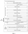
- the obtaining a plurality of poses of an electronic device in a time period includes: obtaining at least one group of sensor data for representing poses of the electronic device; detecting whether data loss occurs in each of the at least one group of sensor data; performing sampling and linear interpolation on at least one group of sensor data in which no data loss occurs, to obtain a plurality of pieces of sensor data; and performing filtering and gravity residual removal operations on the plurality of pieces of sensor data, to obtain the plurality of poses.
- the sensor data includes measurement data of a gyroscope sensor, measurement data of an acceleration sensor, and measurement data of a magnetic sensor.
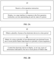
- an embodiment of this application provides a display method, including: receiving a first operation instruction; and displaying, in a map interface in response to the first operation instruction, an icon representing an activity state of a person, where the activity state of the person indicates one or more pieces of the following information: a motion state of the person, an action of the person, and a tool carrying the person.
- the icon in this embodiment of this application may include at least one of a person icon or an object icon.
- the icon is a static image in an image format including a jpg format, a tif format, an img format, or the like.
- the icon is a dynamic image in an image format including a gif format.
- the electronic device displays a map, and the icon is displayed on the map. It can be learned that, in this implementation of this embodiment of this application, the activity state of the person and the map can be presented interactively, so that the electronic device can adaptively present the activity state of the person in real time in the map interface. This optimizes visual effect of a map function and improves user experience.
- the displaying, in a map interface in response to the first operation instruction, an icon representing an activity state of a person includes: displaying the icon in a floating manner in a window in the map interface.
- the displaying, in a map interface in response to the first operation instruction, an icon representing an activity state of a person includes: displaying the icon in a position corresponding to the person related to the icon in the map interface.
- an embodiment of this application provides an electronic device.
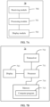
- the electronic device includes a processing module, a receiving module, and a display module.
- the processing module includes functions of performing feature data extraction, classification, and display control in the first aspect, the second aspect, the various possible implementations of the first aspect, and the various possible implementations of the second aspect.
- the receiving module is configured to receive an operation instruction and sensor data in the first aspect, the second aspect, the various possible implementations of the first aspect, and the various possible implementations of the second aspect.
- the display module is configured to perform a function such as displaying an icon in the first aspect, the second aspect, the various possible implementations of the first aspect, and the various possible implementations of the second aspect.
- an embodiment of this application provides an electronic device.
- the electronic device has a function of implementing one or more of the methods in the first aspect, the second aspect, the various possible implementations of the first aspect, and the various possible implementations of the second aspect.
- the function may be implemented by hardware, or may be implemented by hardware executing corresponding software.
- the hardware or the software includes one or more modules corresponding to the foregoing function.
- a structure of the electronic device includes a processor, a receiver, and a display.
- the processor is configured to perform functions except information sending and receiving and displaying in the foregoing method.
- the receiver is configured to receive a user operation instruction.
- the display is configured to display a map and an icon.
- the electronic device may further include a memory.
- the memory is configured to be coupled to the processor, and the memory stores program instructions and data that are necessary for the electronic device.
- an embodiment of this application provides a computer storage medium.
- the computer storage medium stores instructions.
- the computer is enabled to perform some or all steps of the method in the first aspect, the second aspect, the various possible implementations of the first aspect, and the various possible implementations of the second aspect.
- an embodiment of this application provides a computer program product.
- the computer program product runs on a computer, the computer is enabled to perform some or all steps of the method in the first aspect, the second aspect, the various possible implementations of the first aspect, and the various possible implementations of the second aspect.
- the AR module running in the electronic device in embodiments of this application extracts, from the poses of the electronic device by using the stacked one-dimensional convolutional layers, the feature data for representing the activity state of the person. This not only has high scalability, but also ensure that the extracted feature data indicates at least one type of person information. This has a more detailed and accurate representation of the activity state of the person.
- the AR module in the electronic device interacts with the map function, so that the electronic device can adaptively present the activity state of the person in real time in the map interface. This can optimize visual effect of the map function and improve user experience.
- Embodiments of this application provide an activity recognition (activity recognition, AR) method and a display method.
- An electronic device can obtain, by using an AR module based on a one-dimensional convolution principle, an activity state of a person of a user carrying the electronic device, and display, in a map interface, an icon related to the activity state of the person. This can enable a map function of the electronic device to dynamically present the activity state of the person in real time, and optimize user experience.
- the activity state of the person in embodiments of this application refers to a state of the person represented by a motion or an action of the person, and an environmental element associated with the corresponding action.
- the activity state of the person may be represented from at least one dimension, for example, the activity state of the person may be represented from at least one dimension of a motion state of the person, an action of the person, and a tool carrying the person.
- the motion state of the person is a state of the person relative to a reference system when the person performs mechanical motion.
- the motion state of the person may include at least one of standstill, walking and running.
- the action of the person is a body action of the person, and may include at least one of standing, sitting, squatting, lying, and the like.
- the tool carrying the person may include one of a vehicle (for example, in-vehicle, and a high-speed railway), a straight ladder, an escalator, and the like taken by the person.
- a vehicle for example, in-vehicle, and a high-speed railway
- the motion state of the person is "standstill”
- the action of the person is "sitting”
- the tool carrying the person is a "high-speed railway”.
- the activity state of the person is, for example, the user takes the high-speed rail.
- each of the foregoing dimensions may be expressed as one type of feature data of the person.
- a dimension of the motion state of the person is expressed as a first type of feature data
- a dimension of the action of the person is expressed as a second type of feature data
- a dimension of the tool carrying the person is expressed as a third type of feature data, so that the electronic device recognizes the activity state of the person based on different types of feature data.
- a dimension representing the activity state of the person is not limited to the foregoing example.
- the motion state of the person, the action of the person, and the tool carrying the person are not limited to the foregoing examples. Examples are not provided one by one in embodiments of this application.
- the following describes the electronic device, a graphical user interface (user interface, UI) for such an electronic device, and embodiments for such an electronic device.
- UI user interface
- the electronic device in embodiments of this application may be a device including a posture detection function and a display function, for example, an electronic device such as a mobile phone, a tablet computer, a wearable device (for example, a watch, a band, or a helmet), a vehicle-mounted device, or an augmented reality (augmented reality, AR)/virtual reality (virtual reality, VR) device. It may be understood that a specific type of the electronic device is not limited in embodiments of this application.
- the electronic device may be a device running iOS ® , Android ® , Microsoft ® , or another operating system.
- FIG. 1A is a schematic diagram of a hardware structure of an electronic device 100.
- the electronic device 100 may include a processor 110, an external memory interface 120, an internal memory 121, a universal serial bus (universal serial bus, USB) port 130, a charging management module 140, a power management module 141, a battery 142, an antenna 1, an antenna 2, a mobile communication module 150, a wireless communication module 160, an audio module 170, a speaker 170A, a receiver 170B, a microphone 170C, a headset jack 170D, a sensor module 180, a button 190, a motor 191, an indicator 192, a camera 193, a display screen 194, a subscriber identity module (subscriber identification module, SIM) card interface 195, and the like.
- SIM subscriber identity module
- the sensor module 180 may include a pressure sensor 180A, a gyroscope sensor 180B, a barometric pressure sensor 180C, a magnetic sensor 180D, an acceleration sensor 180E, a distance sensor 180F, an optical proximity sensor 180G, a fingerprint sensor 180H, a temperature sensor 180J, a touch sensor 180K, an ambient light sensor 180L, a bone conduction sensor 180M, and the like.
- the structure shown in this embodiment of this application does not constitute a specific limitation on the electronic device 100.
- the electronic device 100 may include more or fewer components than those shown in the figure, or some components may be combined, or some components may be split, or different component arrangements may be used.
- the components shown in the figure may be implemented by hardware, software, or a combination of software and hardware.
- the processor 110 may include one or more processing units.
- the processor 110 may include an application processor (application processor, AP), a modem processor, a graphics processing unit (graphics processing unit, GPU), an image signal processor (image signal processor, ISP), a controller, a memory, a video codec, a digital signal processor (digital signal processor, DSP), a baseband processor, a neural-network processing unit (neural-network processing unit, NPU), and/or the like.
- Different processing units may be independent components, or may be integrated into one or more processors.
- the electronic device 100 may also include one or more processors 110.
- the controller may be a nerve center and a command center of the electronic device 100.
- the controller may generate an operation control signal based on instruction operation code and a time sequence signal, to complete control of instruction detection.
- a memory may be disposed in the processor 110, and is configured to store instructions and data.
- the memory in the processor 110 is a cache memory.
- the memory may store an instruction or data that has been used or cyclically used by the processor 110. If the processor 110 needs to use the instruction or the data again, the processor may directly invoke the instruction or the data from the memory. This avoids repeated access and reduces waiting time of the processor 110, so that efficiency of the electronic device 100 is improved.
- the processor 110 may include one or more interfaces.
- the interface may include an inter-integrated circuit (inter-integrated circuit, I2C) interface, an inter-integrated circuit sound (inter-integrated circuit sound, I2S) interface, a pulse code modulation (pulse code modulation, PCM) interface, a universal asynchronous receiver/transmitter (universal asynchronous receiver/transmitter, UART) interface, a mobile industry processor interface (mobile industry processor interface, MIPI), a general-purpose input/output (general-purpose input/output, GPIO) interface, a subscriber identity module (subscriber identity module, SIM) interface, a universal serial bus (universal serial bus, USB) port, and/or the like.
- I2C inter-integrated circuit
- I2S inter-integrated circuit sound
- PCM pulse code modulation
- PCM pulse code modulation
- UART universal asynchronous receiver/transmitter
- MIPI mobile industry processor interface
- GPIO general-purpose input/output
- the I2C interface is a two-way synchronization serial bus, and includes a serial data line (serial data line, SDA) and a serial clock line (serial clock line, SCL).
- the processor 110 may include a plurality of groups of I2C buses.
- the processor 110 may be separately coupled to the touch sensor 180K, a charger, a flash, the camera 193, and the like through different I2C bus interfaces.
- the processor 110 may be coupled to the touch sensor 180K through the I2C interface, so that the processor 110 communicates with the touch sensor 180K through the I2C bus interface, to implement a touch function of the electronic device 100.
- the I2S interface may be configured to perform audio communication.
- the processor 110 may include a plurality of groups of I2S buses.
- the processor 110 may be coupled to the audio module 170 through the I2S bus, to implement communication between the processor 110 and the audio module 170.
- the audio module 170 may transmit an audio signal to the wireless communication module 160 through the I2S interface, to implement a function of listening to a sound by using a Bluetooth headset.
- the PCM interface may also be used to perform audio communication, and sample, quantize, and code an analog signal.
- the audio module 170 may be coupled to the wireless communication module 160 through a PCM bus interface.
- the audio module 170 may also transmit an audio signal to the wireless communication module 160 through the PCM interface, to implement a function of listening to a sound by using a Bluetooth headset. Both the I2S interface and the PCM interface may be used for audio communication.
- the UART interface is a universal serial data bus, and is configured to perform asynchronous communication.
- the bus may be a two-way communication bus.
- the bus converts to-be-transmitted data between serial communication and parallel communication.
- the UART interface is usually configured to connect the processor 110 to the wireless communication module 160.
- the processor 110 communicates with a Bluetooth module in the wireless communication module 160 through the UART interface, to implement a Bluetooth function.
- the audio module 170 may transmit an audio signal to the wireless communication module 160 through the UART interface, to implement a function of playing music by using a Bluetooth headset.
- the MIPI interface may be configured to connect the processor 110 to a peripheral component such as the display screen 194.
- the MIPI interface includes a display serial interface (display serial interface, DSI) and the like.
- the processor 110 communicates with the display screen 194 through the DSI interface, to implement a display function of the electronic device 100.
- the GPIO interface may be configured by software.
- the GPIO interface may be configured as a control signal or a data signal.
- the GPIO interface may be configured to connect the processor 110 to the camera 193, the display screen 194, the wireless communication module 160, the audio module 170, the sensor module 180, or the like.
- the GPIO interface may alternatively be configured as an I2C interface, an I2S interface, a UART interface, an MIPI interface, or the like.
- the USB port 130 is a port that conforms to a USB standard specification, and may be specifically a mini USB port, a micro USB port, a USB type-C port, or the like.
- the USB port 130 may be configured to connect to a charger to charge the electronic device 100, or may be configured to transmit data between the electronic device 100 and a peripheral device, or may be configured to connect to a headset for playing audio through the headset.
- the port may be configured to connect to another electronic device such as an AR device.
- an interface connection relationship between the modules shown in this embodiment of this application is merely an example for description, and does not constitute a limitation on the structure of the electronic device 100.
- the electronic device 100 may alternatively use an interface connection manner different from an interface connection manner in the foregoing embodiment, or use a combination of a plurality of interface connection manners.
- the charging management module 140 is configured to receive a charging input from a charger.
- the charger may be a wireless charger or a wired charger.
- the charging management module 140 may receive a charging input of a wired charger through the USB port 130.
- the charging management module 140 may receive a wireless charging input through a wireless charging coil of the electronic device 100.
- the charging management module 140 may further supply power to the electronic device 100 through the power management module 141 while charging the battery 142.
- the power management module 141 is configured to be connected to the battery 142, the charging management module 140, and the processor 110.
- the power management module 141 receives an input from the battery 142 and/or the charging management module 140, and supplies power to the processor 110, the internal memory 121, the display screen 194, the camera 193, the wireless communication module 160, and the like.
- the power management module 141 may be configured to monitor parameters such as a battery capacity, a battery cycle count, and a battery health status (electric leakage or impedance).
- the power management module 141 may alternatively be disposed in the processor 110.
- the power management module 141 and the charging management module 140 may alternatively be disposed in a same component.
- a wireless communication function of the electronic device 100 may be implemented through the antenna 1, the antenna 2, the mobile communication module 150, the wireless communication module 160, the modem processor, the baseband processor, and the like.
- the antenna 1 and the antenna 2 are configured to transmit and receive an electromagnetic wave signal.
- Each antenna in the electronic device 100 may be configured to cover one or more communication frequency bands. Different antennas may be multiplexed, to improve antenna utilization.
- the antenna 1 may be multiplexed as a diversity antenna of a wireless local area network.
- the antenna may be used in combination with a tuning switch.
- the mobile communication module 150 may provide a solution that is applied to the electronic device 100 and that includes wireless communication such as 2G/3G/4G/5G.
- the mobile communication module 150 may include at least one filter, a switch, a power amplifier, a low noise amplifier (low noise amplifier, LNA), and the like.
- the mobile communication module 150 may receive an electromagnetic wave through the antenna 1, perform processing such as filtering or amplification on the received electromagnetic wave, and transmit the electromagnetic wave to the modem processor for demodulation.
- the mobile communication module 150 may further amplify a signal modulated by the modem processor, and convert the signal into an electromagnetic wave for radiation through the antenna 1.
- at least some functional modules in the mobile communication module 150 may be disposed in the processor 110.
- at least some functional modules in the mobile communication module 150 may be disposed in a same device as at least some modules in the processor 110.
- the modem processor may include a modulator and a demodulator.
- the modulator is configured to modulate a to-be-sent low-frequency baseband signal into a medium-high frequency signal.
- the demodulator is configured to demodulate a received electromagnetic wave signal into a low-frequency baseband signal. Then, the demodulator transmits the low-frequency baseband signal obtained through demodulation to the baseband processor for processing.
- the low-frequency baseband signal is processed by the baseband processor and then transmitted to the application processor.
- the application processor outputs a sound signal by using an audio device (which is not limited to the speaker 170A, the receiver 170B, or the like), or displays an operation interface of an app on the display screen 194.
- the modem processor may be an independent component.
- the modem processor may be independent of the processor 110, and is disposed in a same device as the mobile communication module 150 or another functional module.
- the wireless communication module 160 may provide a wireless communication solution that is applied to the electronic device 100 and that includes a wireless local area network (wireless local area network, WLAN) (for example, a wireless fidelity (wireless fidelity, Wi-Fi) network), Bluetooth (Bluetooth, BT), a global navigation satellite system (global navigation satellite system, GNSS), frequency modulation (frequency modulation, FM), a near field communication (near field communication, NFC) technology, an infrared (infrared, IR) technology, or the like.
- the wireless communication module 160 may be one or more components integrating at least one communication processor module.
- the wireless communication module 160 receives an electromagnetic wave through the antenna 2, performs frequency modulation and filtering processing on an electromagnetic wave signal, and sends a processed signal to the processor 110.
- the wireless communication module 160 may further receive a to-be-sent signal from the processor 110, perform frequency modulation and amplification on the signal, and convert the signal into an electromagnetic wave for radiation through the antenna 2.
- the antenna 1 and the mobile communication module 150 are coupled, and the antenna 2 and the wireless communication module 160 are coupled, so that the electronic device 100 can communicate with a network and another device by using a wireless communication technology.
- the wireless communication technology may include a global system for mobile communications (global system for mobile communications, GSM), a general packet radio service (general packet radio service, GPRS), code division multiple access (code division multiple access, CDMA), wideband code division multiple access (wideband code division multiple access, WCDMA), time-division code division multiple access (time-division code division multiple access, TD-SCDMA), long term evolution (long term evolution, LTE), BT, a GNSS, a WLAN, NFC, FM, an IR technology, and/or the like.
- GSM global system for mobile communications
- GPRS general packet radio service
- code division multiple access code division multiple access
- CDMA wideband code division multiple access
- WCDMA wideband code division multiple access
- time-division code division multiple access time-division code
- the GNSS may include a global positioning system (global positioning system, GPS), a global navigation satellite system (global navigation satellite system, GLONASS), a BeiDou navigation satellite system (BeiDou navigation satellite system, BDS), a quasi-zenith satellite system (quasi-zenith satellite system, QZSS), and/or a satellite based augmentation system (satellite based augmentation system, SBAS).
- GPS global positioning system
- GLONASS global navigation satellite system
- BeiDou navigation satellite system BeiDou navigation satellite system
- BDS BeiDou navigation satellite system
- QZSS quasi-zenith satellite system
- SBAS satellite based augmentation system
- the wireless communication solution provided by the mobile communication module 150 may enable the electronic device 100 to communicate with a device (such as a cloud server) in a network.
- the WLAN wireless communication solution provided by the wireless communication module 160 may also enable the electronic device 100 to communicate with a device (such as a cloud server) in a network.
- the electronic device 100 may implement a display function through the GPU, the display screen 194, the application processor, and the like.
- the GPU is a microprocessor for image processing, and is connected to the display screen 194 and the application processor.
- the GPU is configured to: perform mathematical and geometric computation, and render an image.
- the GPU may perform rendering to obtain an image representing an activity state of a person.
- the processor 110 may include one or more GPUs that execute program instructions to generate a display interface of a map app.
- the display screen 194 may include a display and a touch device.
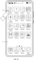
- the display is configured to output displayed content to a user, for example, an application (application, APP) icon display interface of the electronic device 100, a map display interface, and a display interface for representing an activity state of a person in the map interface.
- the touch control device is configured to receive an operation instruction input by a user on the display screen 194.
- the display screen 194 includes a display panel.
- the display panel may be a liquid crystal display (liquid crystal display, LCD), an organic light-emitting diode (organic light-emitting diode, OLED), an active-matrix organic light emitting diode (active-matrix organic light emitting diode, AMOLED), a flexible light-emitting diode (flexible light-emitting diode, FLED), a mini-LED, a micro-LED, a micro-OLED, a quantum dot light emitting diode (quantum dot light emitting diode, QLED), or the like.
- the display screen 194 when the display panel is made of a material such as an OLED, an AMOLED, or an FLED, the display screen 194 may be bent.
- that the display screen 194 may be bent means that the display screen may be bent to any angle at any part and may be maintained at the angle.
- the display screen 194 may be folded left and right in the middle, or may be folded up and down in the middle.
- the electronic device 100 may implement a photographing function through the camera 193, the ISP, the video codec, the GPU, the display screen 194, the application processor, and the like.
- the NPU is a neural-network (neural-network, NN) computing processor, quickly processes input information by referring to a structure of a biological neural network, for example, by referring to a mode of transmission between human brain neurons, and may further continuously perform self-learning.
- Applications such as intelligent cognition of the electronic device 100 may be implemented through the NPU, for example, image recognition, facial recognition, speech recognition, and text understanding.
- the external memory interface 120 may be configured to connect to an external storage card, for example, a micro SD card, to extend a storage capability of the electronic device 100.
- the external memory card communicates with the processor 110 through the external memory interface 120, to implement a data storage function. For example, data such as music, a photo, and a video is stored in the external storage card.
- the internal memory 121 may be configured to store one or more computer programs, and the one or more computer programs include instructions.
- the processor 110 may run the instructions stored in the internal memory 121, so that the electronic device 100 performs the display method provided in some embodiments of this application, various data processing, and the like.
- the internal memory 121 may include a program storage area and a data storage area.
- the program storage area may store an operating system.
- the program storage area may further store one or more applications (such as Map, Email, and Contact), and the like.
- the data storage area may store data required in a use process of the electronic device 100 (for example, an algorithm for recognizing an activity state of a person, and an icon description file), and created data (such as sensor measurement data).
- the internal memory 121 may include a high-speed random access memory, or may include a nonvolatile memory, for example, at least one magnetic disk storage device, a flash memory, or a universal flash storage (universal flash storage, UFS).
- the electronic device 100 may implement an audio function, for example, music playing and recording, through the audio module 170, the speaker 170A, the receiver 170B, the microphone 170C, the headset jack 170D, the application processor, and the like.
- an audio function for example, music playing and recording
- the audio module 170 is configured to convert digital audio information into an analog audio signal for output, and is also configured to convert an analog audio input into a digital audio signal.
- the audio module 170 may be configured to code and decode an audio signal.
- the audio module 170 may be disposed in the processor 110, or some functional modules in the audio module 170 are disposed in the processor 110.
- the speaker 170A also referred to as a "loudspeaker" is configured to convert an audio electrical signal into a sound signal.
- the electronic device 100 may be used to listen to music or answer a call in a hands-free mode over the speaker 170A.
- the receiver 170B also referred to as an "earpiece", is configured to convert an electrical audio signal into a sound signal.
- the receiver 170B may be put close to a human ear to listen to a voice.
- the microphone 170C also referred to as a "mike” or “mic”, is configured to convert a sound signal into an electrical signal.
- a user may make a sound near the microphone 170C through the mouth of the user, to input a sound signal to the microphone 170C.
- At least one microphone 170C may be disposed in the electronic device 100.
- two microphones 170C may be disposed in the electronic device 100, to collect a sound signal and implement a noise reduction function.
- three, four, or more microphones 170C may alternatively be disposed in the electronic device 100, to collect a sound signal, implement noise reduction, and identify a sound source, so as to implement a directional recording function and the like.
- the headset jack 170D is configured to connect to a wired headset.
- the headset jack 170D may be a USB port 130, or may be a 3.5 mm open mobile terminal platform (open mobile terminal platform, OMTP) standard interface or cellular telecommunications industry association of the USA (cellular telecommunications industry association of the USA, CTIA) standard interface.
- the pressure sensor 180A is configured to sense a pressure signal, and can convert the pressure signal into an electrical signal.
- the pressure sensor 180A may be disposed on the display screen 194.
- the capacitive pressure sensor may include at least two parallel plates made of conductive materials.
- the gyroscope sensor 180B may detect a pose change of the electronic device 100 by detecting rotation angles of the electronic device 100 around three axes (namely, an x-axis, a y-axis, and a z-axis), and further determine behavior of a user carrying the electronic device 100.
- the user for example, holds the electronic device 100.
- the electronic device 100 continuously has a slight displacement with an action of the user, and rotation angles of the electronic device 100 relative to the three axes continuously change with a body posture of the user.
- the electronic device 100 obtains measurement data of the gyroscope sensor 180B, and determines a pose change of the electronic device 100 based on the measurement data of the gyroscope sensor 180B. This can determine a posture change of the user.
- the acceleration sensor 180E may detect magnitudes of accelerations of the electronic device 100 in a plurality of directions (generally an x-axis, a y-axis, and a z-axis), determine an activity direction of the electronic device 100, and determine a behavior action of the user carrying the electronic device 100. For example, a user, for example, holds the electronic device 100. In a process in which the user walks upstairs, the electronic device 100 may obtain accelerations (namely, measurement data of the acceleration sensor 180E) detected by the acceleration sensor 180E in x-axis, y-axis, and z-axis directions, and then determine an activity direction of the electronic device 100 based on the measurement data of the acceleration sensor 180E and further determine behavior of the user.
- accelerations namely, measurement data of the acceleration sensor 180E
- the magnetic sensor 180D may include a Hall effect sensor.
- the magnetic sensor 180D may determine an orientation of the display screen 194 by detecting a magnitude and a direction of a magnetic field. For example, the electronic device 100 may determine, based on the magnetic sensor 180D, that the display screen 194 is parallel to the ground and the display screen 194 faces upward. Further, the electronic device 100 may correctly mark an icon or the like in an interface of a map app based on the orientation of the display screen 194. In some embodiments, when the electronic device 100 is a flexible screen device, the electronic device 100 may detect a folded state and an unfolded state of a screen based on the magnetic sensor 180D. Details are not described herein again.
- data detected by the gyroscope sensor 180B for example, a rotation angle of a gyroscope
- measurement data of the gyroscope sensor 180B data detected by the acceleration sensor 180E, for example, a magnitude and a direction of gravity
- measurement data of the acceleration sensor 180E for example, a magnitude and a direction of gravity
- magnetic sensor 180D data detected by the magnetic sensor 180D.
- the measurement data of the gyroscope sensor 180B, the measurement data of the acceleration sensor 180E, and the measurement data of the magnetic sensor 180D may reflect the pose change of the electronic device 100, the measurement data of the acceleration sensor 180E may reflect a moving speed of the electronic device 100, and the like. Therefore, the activity state of the user carrying the electronic device 100 can be determined.
- the barometric pressure sensor 180C is configured to measure barometric pressure. In some embodiments, the electronic device 100 calculates an altitude through the barometric pressure measured by the barometric pressure sensor 180C, to assist in positioning and navigation.
- the distance sensor 180F is configured to measure a distance.
- the electronic device 100 may measure the distance in an infrared manner or a laser manner. In some embodiments, in a photographing scenario, the electronic device 100 may measure a distance through the distance sensor 180F to implement quick focusing.
- the optical proximity sensor 180G may include, for example, a light emitting diode (LED) and an optical detector, for example, a photodiode.
- the light emitting diode may be an infrared light emitting diode.
- the electronic device 100 emits infrared light by using the light-emitting diode.
- the electronic device 100 detects infrared reflected light from a nearby object through the photodiode. When sufficient reflected light is detected, it may be determined that there is an object near the electronic device 100. When insufficient reflected light is detected, the electronic device 100 may determine that there is no object near the electronic device 100.
- the electronic device 100 may detect, by using the optical proximity sensor 180G, that the user holds the electronic device 100 close to an ear for a call, to automatically turn off a screen for power saving.
- the optical proximity sensor 180G may also be used in a smart cover mode or a pocket mode to automatically perform screen unlocking or locking.
- the ambient light sensor 180L is configured to sense ambient light brightness.
- the electronic device 100 may adaptively adjust brightness of the display screen 194 based on the sensed ambient light brightness.
- the ambient light sensor 180L may also be configured to automatically adjust white balance during photographing.
- the ambient light sensor 180L may also cooperate with the optical proximity sensor 180G to detect whether the electronic device 100 is in a pocket, to avoid an accidental touch.
- the fingerprint sensor 180H is configured to collect a fingerprint.
- the electronic device 100 may use a feature of the collected fingerprint to implement fingerprint-based unlocking, application lock access, fingerprint-based photographing, fingerprint-based call answering, and the like.
- the temperature sensor 180J is configured to detect a temperature.
- the electronic device 100 executes a temperature processing policy through the temperature detected by the temperature sensor 180J. For example, when the temperature reported by the temperature sensor 180J exceeds a threshold, the electronic device 100 lowers performance of a processor nearby the temperature sensor 180J, to reduce power consumption for thermal protection. In some other embodiments, when the temperature is less than another threshold, the electronic device 100 heats the battery 142 to prevent the electronic device 100 from being shut down abnormally due to a low temperature. In some other embodiments, when the temperature is lower than still another threshold, the electronic device 100 boosts an output voltage of the battery 142 to avoid abnormal shutdown caused by a low temperature.
- the touch sensor 180K may also be referred to as a touch panel or a touch-sensitive surface.
- the touch sensor 180K may be disposed on the display screen 194, and the touch sensor 180K and the display screen 194 form a touchscreen, which is also referred to as a "touch control screen".
- the touch sensor 180K is configured to detect a touch operation performed on or near the touch sensor.
- the touch sensor may transfer the detected touch operation to the application processor to determine a type of a touch event.
- a visual output related to the touch operation may be provided through the display screen 194.
- the touch sensor 180K may also be disposed on a surface of the electronic device 100 at a position different from that of the display screen 194.
- the bone conduction sensor 180M may obtain a vibration signal.
- the bone conduction sensor 180M may obtain a vibration signal of a vibration bone of a human vocal-cord part.
- the bone conduction sensor 180M may also be in contact with a body pulse to receive a blood pressure beating signal.
- the bone conduction sensor 180M may also be disposed in the headset, to obtain a bone conduction headset.
- the audio module 170 may obtain a speech signal through parsing based on the vibration signal that is of the vibration bone of the vocal-cord part and that is obtained by the bone conduction sensor 180M, to implement a speech function.
- the application processor may parse heart rate information based on the blood pressure beating signal obtained by the bone conduction sensor 180M, to implement a heart rate detection function.
- the button 190 includes a power button, a volume button, and the like.
- the button 190 may be a mechanical button, or may be a touch button.
- the electronic device 100 may receive a button input, and generate a button signal input related to a user setting and function control of the electronic device 100.
- the motor 191 may generate a vibration prompt.
- the motor 191 may be configured to provide an incoming call vibration prompt and a touch vibration feedback.
- touch operations performed on different applications may correspond to different vibration feedback effect.
- the motor 191 may also correspond to different vibration feedback effect for touch operations performed on different areas of the display screen 194.
- Different application scenarios for example, a time reminder, information receiving, an alarm clock, and a game
- Touch vibration feedback effect may be customized.
- the indicator 192 may be an indicator light, and may be configured to indicate a charging status and a power change, or may be configured to indicate a message, a missed call, a notification, and the like.
- the SIM card interface 195 is configured to connect to a SIM card.
- the SIM card may be inserted into the SIM card interface 195 or removed from the SIM card interface 195, to implement contact with or separation from the electronic device 100.
- the electronic device 100 may support one or N SIM card interfaces, where N is a positive integer greater than 1.
- the SIM card interface 195 may support a nano-SIM card, a micro-SIM card, a SIM card, and the like.
- a plurality of cards may be inserted into a same SIM card interface 195 at the same time.
- the plurality of cards may be of a same type or different types.
- the SIM card interface 195 may be compatible with different types of SIM cards.
- the SIM card interface 195 is also compatible with an external storage card.
- the electronic device 100 interacts with a network through the SIM card, to implement functions such as conversation and data communication.
- the electronic device 100 uses an eSIM, that is, an embedded SIM card.
- the eSIM card may be embedded into the electronic device 100, and cannot be separated from the electronic device 100.
- a software system of the electronic device 100 may use a layered architecture, an event-driven architecture, a microkernel architecture, a micro service architecture, or a cloud architecture.
- an Android system with a layered architecture is used as an example to describe a software structure of the electronic device 100.
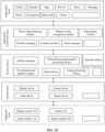
- FIG. 1B is a schematic diagram of the software structure of the electronic device 100 according to this embodiment of this application.
- the layered architecture software is divided into several layers, and each layer has a clear role and task.
- the layers communicate with each other through a software interface.
- the Android system is divided into an application layer, an application framework layer, an Android runtime (Android runtime) and system library, and a kernel layer from top to bottom.
- the application layer may include a series of application packages.
- the application packages may include applications such as Gallery, Calendar, Map, WLAN, Music, Messages, Phone, Navigation, Bluetooth, and Videos.
- the application framework layer provides an application programming interface (application programming interface, API) and a programming framework for an application at the application layer.
- the application framework layer includes some predefined functions.
- the application framework layer may include a sensor data obtaining module, an AR module, and a map display module.
- the application framework layer may further include a window manager, a content provider, a view system, a phone manager, a resource manager, a notification manager, and the like. This is not limited in this embodiment of this application.
- the sensor data obtaining module may be configured to: obtain sensor data that reflects a posture of the electronic device 100, and transmit the obtained sensor data to the AR module.
- the sensor data includes, for example, the measurement data of the gyroscope sensor 180B, the measurement data of the acceleration sensor 180E, and the measurement data of the magnetic sensor 180D.
- the sensor data obtaining module may obtain measurement data of at least one sensor, to obtain at least one group of measurement data. It should be noted that different sensors have different detection periods. Further, the sensor data obtaining module may obtain measurement data of a sensor based on a detection period of the corresponding sensor. Therefore, the sensor data obtaining module obtains measurement data of each sensor at different frequencies. For example, the sensor data obtaining module obtains the measurement data of the magnetic sensor 180D at a frequency of 500 Hz (Hz), and the sensor data obtaining module obtains the measurement data of the acceleration sensor 180E at a frequency of 200 Hz.
- Hz 500 Hz
- the measurement data of the gyroscope sensor 180B, the measurement data of the acceleration sensor 180E, and the measurement data of the magnetic sensor 180D are merely example descriptions, and the sensor data in this embodiment of this application is not limited. In some other embodiments, the sensor data may further include more or less sensor measurement data that can represent the posture of the electronic device 100.
- the AR module may be configured to: obtain data of an activity state of a person based on the sensor data, and transmit the data of the activity state of the person to the map display module.
- the AR module may include a data preprocessing module, a feature extraction module, and a classification module (neither shown in FIG. 1B ).
- the data preprocessing module may be configured to pre-process sensor data;
- the feature extraction module may be configured to perform feature extraction on preprocessed data, so as to obtain a feature data group for representing an activity state of a person;
- the classification module may be configured to extract at least one type of feature data from the feature data group, where each piece of feature data is data of the activity state of the person at one dimension.
- both the feature extraction module and the classification module implement related functions based on a one-dimensional convolution algorithm principle.
- a model for implementing a function of the feature extraction module is also referred to as a time series embedding (time series embedding, TSE) model
- the classification module may also be referred to as a classifier. This is not limited in this embodiment of this application.
- the map display module may be configured to manage a display policy of a map function of the electronic device 100, including determining a display mode of an icon, determining a display position of the icon, and the like.
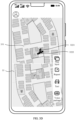
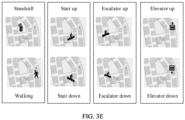
- the map display module may be configured to render a to-be-displayed icon. Then, the map display module may control, by using a display driver and a surface manager (surface manager) in a bottom-layer display system, the map app to display, on the display screen 194 of the electronic device 100 according to a display policy, the icon representing the activity state of the person, and present a visualized behavior state (display effect shown in FIG. 3B to FIG. 3E ) to the user.
- the window manager is configured to manage a window program.
- the window manager may obtain a size of the display screen, determine whether there is a status bar, perform screen locking, take a screenshot, and the like.
- the content provider is configured to: store and obtain data, and enable the data to be accessed by an application.
- the data may include a video, an image, an audio, calls that are made and answered, a browsing history and bookmarks, an address book, and the like.
- the view system includes visual controls such as a control for displaying a text and a control for displaying an image.
- the view system may be configured to construct an application.
- a display interface may include one or more views, for example, a display interface including a camera icon.
- the phone manager is configured to provide a communication function for the electronic device 100, for example, management of a call status (including answering, declining, or the like).
- the resource manager provides various resources such as a localized character string, an icon, an image, a layout file, and a video file for an application.
- the notification manager enables an application to display notification information in a status bar, and may be configured to convey a notification message.
- the notification information may automatically disappear after a short pause without requiring a user interaction.
- the notification manager is configured to notify download completion, give a message notification, and the like.
- the notification manager may alternatively be a notification that appears in a top status bar of the system in a form of a graph or a scroll bar text, for example, a notification of an application that is run on a background, or may be a notification that appears on the screen in a form of a dialog window.
- text information is displayed in the status bar, an alert sound is played, the electronic device 100 vibrates, or the indicator light blinks.
- the Android runtime (Android Runtime) includes a core library and a virtual machine.
- the Android runtime is responsible for scheduling and management of the Android system.
- the kernel library includes two parts: a function that needs to be called in Java language and a kernel library of Android.
- the system library, the kernel layer, and the like below the application framework layer may be referred to as an underlying system.
- the underlying system includes an underlying display system configured to provide a display service.
- the underlying display system includes a display driver at the kernel layer, a surface manager in the system library, and the like.
- the system library may include a plurality of functional modules, for example, a surface manager (surface manager), a media library (media library), a three-dimensional graphics processing library (for example, OpenGL ES), and a 2D graphics engine (for example, SGL).
- a surface manager surface manager
- media library media library
- three-dimensional graphics processing library for example, OpenGL ES
- 2D graphics engine for example, SGL
- the surface manager is configured to manage a display subsystem and provide fusion of 2D and 3D layers for a plurality of applications.
- the media library supports playback and recording in a plurality of commonly used audio and video formats, and static image files.
- the media library may support a plurality of audio and video encoding formats such as MPEG-4, H.264, MP3, AAC, AMR, JPG, and PNG.
- the three-dimensional graphics processing library is configured to implement three-dimensional graphics drawing, image rendering, composition, layer processing, and the like.
- the 2D graphics engine is a drawing engine for 2D drawing.
- the kernel layer is a layer between hardware and software.
- the kernel layer includes at least a display driver, a camera driver, an audio driver, and a sensor driver.
- a UI for implementing a display function in embodiments of this application is a medium interface for interaction and information exchange between an application or an operating system and a user, and implements conversion between an internal form of information and a form acceptable to the user.
- a user interface of an application is source code written in a specific computer language, for example, Java or an extensible markup language (extensible markup language, XML).
- Interface source code is parsed and rendered on an electronic device, and is finally presented as content that can be identified by the user, for example, a control such as a video, a picture, a text, or a button.
- the control also referred to as a widget (widget), is a basic element on the user interface.
- Typical controls include a toolbar (toolbar), a menu bar (menu bar), a text box (text box), a button (button), a scrollbar (scrollbar), a picture, and a text.
- An attribute and content of a control on an interface are defined by using a tag or a node.
- the control included in the interface is defined in the XML by using a node, for example, ⁇ Textview>, ⁇ ImgView>, or ⁇ VideoView>.
- One node corresponds to one control or one attribute on the interface. After being parsed and rendered, the node is presented as user-visible content.
- interfaces of many applications such as a hybrid application (hybrid application) usually further include a web page.
- a web page also referred to as a page, may be understood as a special control embedded in an interface of an application.
- a web page is source code written in a specific computer language, for example, a hypertext markup language (hypertext markup language, HTML), cascading style sheets (cascading style sheets, CSS), or JavaScript (JavaScript, JS).
- the web page source code may be loaded and displayed as user-recognizable content by a browser or a web page display component with a function similar to a function of the browser.
- Specific content included in the web page is also defined by using a tag or a node in the web page source code.
- an element and an attribute of the web page are defined in the HTML by using ⁇ p>, ⁇ img> ⁇ video>, or ⁇ canvas>.
- the user interface is usually represented in a form of a graphical user interface (graphical user interface, GUI), and is a user interface that is related to a computer operation and that is displayed in a graphic manner.
- GUI graphical user interface
- the user interface may be an interface element such as an icon, a window, or a control displayed on a display of an electronic device, and the control may include a visual interface element such as an icon, a button, a menu, a tab, a text box, a dialog box, a status bar, a navigation bar, or a widget.
- the electronic device does not have a function of detecting an activity state of a person, or the electronic device has a function of detecting an activity state of a person, but the function of detecting the activity state of the person and a map display function are independent of each other due to no requirement. Therefore, the electronic device cannot provide a service of displaying the activity state of the person on a map, and can provide only a service directly related to a position of a user carrying the electronic device. As a result, the map function has a single associated service item, and user experience is low.
- an embodiment of this application provides a display method 10.
- the display method 10 includes: The electronic device 100 receives a first operation instruction, and then the electronic device 100 displays, in a map interface in response to the first operation instruction, an icon representing an activity state of a person.
- the icon includes a person icon, for example, a person vector diagram (an icon in a "walking scenario" shown in FIG. 3C ).
- the icon includes an object icon, for example, an elevator vector diagram, an escalator vector diagram, or a bicycle vector diagram.
- the icon includes a person icon and an object icon, and the person icon and the object icon are displayed in combination. For example, a person vector diagram is close to a stair shown in a stair vector diagram (an icon in a "stair up scenario" in FIG. 3C ).
- the icon is a static image (an icon in a "standstill scenario" in FIG. 3C ) in an image format including a jpg format, a tif format, and an img format.
- the icon is a dynamic image (a person icon illustrated in each of FIG. 3F and FIG. 3G ) in an image format including a gif format.
- when the icon includes the person icon and the object icon at least one of the person icon and the object icon is a dynamic image. As shown in FIG. 3D , a person icon is a dynamic image, and a stair icon is a static image. This is not limited herein.
- the electronic device 100 may further preset at least one display mode, and each display mode indicates a display manner of the icon in the map app interface. For example, a first display mode indicates that the icon is displayed in a floating manner in the map app interface (as shown in FIG. 3B ); a second display mode indicates that the icon is embedded in the map app interface, and the map app interface is presented in a plan view (as shown in FIG. 3D ); and a third display mode indicates that the icon is embedded in the map app interface, and the map app interface is presented in a sectional view.
- the display method 10 may further include: The electronic device 100 receives a second operation instruction input by a user, and then the electronic device 100 displays, in a display mode indicated by the second operation instruction, the icon representing the activity state of the person.
- the activity state of the person and a map can be presented interactively, so that the electronic device 100 can adaptively present the activity state of the person in real time in the map interface. This optimizes visual effect of a map function and improves user experience.
- the map function of the electronic device 100 may be implemented on the map app installed on the electronic device 100, or may be implemented by using a map plug-in or a map applet of another app on the electronic device 100, for example, a map plug-in in an instant chat app.
- FIG. 2B shows an activity recognition method 20.
- the electronic device 100 can obtain the icon representing the activity state of the person in the display method 10.
- the activity recognition method 20 may include: The electronic device 100 obtains a plurality of poses of the electronic device 100 in a time period, and then obtains one or more pieces of feature data based on the plurality of poses by using a plurality of one-dimensional convolutional layers, where the one or more pieces of feature data indicate different types of information of a person holding the electronic device 100 in the time period, and a type of information indicated by each piece of feature data may be a motion state of the person, an action of the person, or a tool carrying the person. Further, the electronic device 100 is controlled to display, as an icon, the types of the information indicated by the one or more pieces of feature data.
- the electronic device 100 may control the electronic device 100 to display a map, and after obtaining the icon corresponding to each piece of feature data, control the corresponding icon to be displayed on the map, so as to implement the display function in the display method 10.
- the "time period" in this embodiment may be flexibly set based on a requirement. This is not limited herein. In an optional example, the time period is, for example, 5s.
- the electronic device 100 obtains the one or more pieces of feature data based on the plurality of poses may specifically include: The electronic device obtains a feature data group based on the plurality of poses by using the plurality of one-dimensional convolutional layers, where the feature data group includes at least one type of information of the activity state of the person. Further, the electronic device 100 obtains each of the foregoing types of feature data from the feature data group, to obtain the one or more pieces of feature data.
- FIG. 2C shows an activity recognition method 200.
- the activity recognition method 200 is a possible implementation of the activity recognition method 20.
- the activity recognition method 200 includes: The electronic device 100 obtains at least one group of measurement data, where each group of measurement data in the at least one group of measurement data corresponds to one sensor. Further, the electronic device 100 performs data preprocessing on the at least one group of measurement data, to obtain a plurality of poses of the electronic device 100. Then, the electronic device 100 performs feature extraction on the plurality of poses by using a time series embedding (time series embedding, TSE) model, to obtain a feature data group. Further, the electronic device 100 performs classification on the feature data group by using a classifier to obtain each type of feature data.
- TSE time series embedding
- the electronic device 100 performs preprocessing on the at least one group of measurement data may include: The electronic device 100 checks each group of measurement data, to determine whether an abnormality (for example, data loss) occurs in the obtained measurement data, and then samples measurement data that passes the check (namely, measurement data on which no abnormality occurs), to unify time intervals of groups of measurement data. Then, the electronic device 100 performs linear interpolation on each group of sampled data, to obtain a group of data. Further, the electronic device 100 performs operations such as noise reduction and gravity residual removal on the obtained group of data, to obtain the plurality of poses of the electronic device 100. Then, the electronic device 100 obtains data of the activity state of the person based on the plurality of poses.
- an abnormality for example, data loss
- samples measurement data that passes the check namely, measurement data on which no abnormality occurs
- the electronic device 100 performs linear interpolation on each group of sampled data, to obtain a group of data.
- the electronic device 100 performs operations such as noise reduction and gravity residual removal on the
- FIG. 2D shows an example of an operation flow of obtaining the data of the activity state of the person based on the plurality of poses.
- the operation flow is implemented based on a TSE model and a classifier.
- the TSE model in this embodiment of this application may include a first feature extraction framework and a second feature extraction framework.
- the first feature extraction framework includes m one-dimensional convolutional layers in serial combination
- the second feature extraction framework includes n backbone (backbone) models in serial combination.
- Each backbone model includes at least two one-dimensional convolutional layers in parallel combination, a quantity of one-dimensional convolutional layers in different backbone models may be the same or may be different, and m and n each are a positive integer.
- the first feature extraction framework performs feature extraction on the plurality of poses, to obtain an initial feature data group
- the second feature extraction framework performs feature extraction on the initial feature data group from different time scales, to obtain a feature data group associated with time.
- the classifier extracts at least one type of feature data from the feature data group, to obtain the data of the activity state of the person.
- a first one-dimensional convolutional layer in the first feature extraction framework receives the plurality of poses, and then the first one-dimensional convolutional layer performs feature extraction on the plurality of poses, to obtain a first initial feature data group; further, a second one-dimensional convolutional layer in the first feature extraction framework performs feature extraction on the first initial feature data group, to obtain a second initial feature data group; ...; and an m th one-dimensional convolutional layer in the first feature extraction framework performs feature extraction on a data group extracted by an (m-1) th one-dimensional convolutional layer, to obtain the initial feature data group.
- An operating principle of a one-dimensional convolution model is to perform feature extraction on input one-dimensional features in a quantity of channels, where a feature extracted in each channel is different from a feature extracted in another channel. Therefore, a larger quantity of channels of a convolutional layer indicates higher accuracy of the feature extracted by the convolutional layer for activity recognition.
- quantities of channels of the one-dimensional convolutional layers in the first feature extraction framework may increase sequentially based on a data flow direction. For example, a quantity of channels of the first one-dimensional convolutional layer in the first feature extraction framework is 32, and a quantity of channels of the second one-dimensional convolutional layer in the first feature extraction framework is 64. In this way, the first feature extraction framework gradually performs deeper feature extraction on the plurality of poses, to ensure that the activity state of the person represented by the initial feature data group meets a preset condition.
- the quantities of channels of the one-dimensional convolutional layers in the first feature extraction framework increase sequentially is merely an example implementation, and constitutes no limitation in this embodiment of this application.
- all or some of quantities of channels of the one-dimensional convolutional layers in the first feature extraction framework may be the same.
- the quantities of channels of the one-dimensional convolutional layers in the first feature extraction framework may decrease sequentially. This is not limited in this embodiment of this application.
- the first feature extraction framework only needs to perform preliminary feature extraction on the plurality of poses. Therefore, values of kernels (kernels, k) of the m one-dimensional convolutional layers in the first feature extraction framework are the same.
- a value of k indicates a quantity of consecutive pose data in a plurality of poses used in each convolution operation. Further, the plurality of poses are obtained by sampling based on a time dimension. Therefore, the value of k is related to a time scale. It indicates that the initial feature data group is related to only one time scale.
- the second feature extraction framework further performs feature extraction on the initial feature data group from a time scale, to obtain the feature data group.
- a first backbone model in the second feature extraction framework receives the initial feature data group, and then the first backbone model performs feature extraction on the initial feature data group from a time scale, to obtain a first feature data group; further, a second backbone model in the second feature extraction framework performs feature extraction on the first feature data group from a time scale, to obtain a second feature data group; ...; and after an n th backbone model in the second feature extraction framework performs feature extraction on a data group extracted by an (n-1) th backbone model, the feature data group is obtained.
- Implementation processes of the n backbone models in the second feature extraction framework are similar. Descriptions are provided below by using a first backbone model as an example.
- the first backbone model is any one of the n backbone models.
- the first backbone model may separately input an input feature data group into at least two one-dimensional convolutional layers in the first backbone model.
- the at least two one-dimensional convolutional layers each perform a convolution operation on the input feature data group, and output a data group obtained through the operation.
- the first backbone model forms data groups output by the at least two one-dimensional convolutional layers into one data group, and then outputs the data group.
- Values of k of the at least two one-dimensional convolutional layers in the first backbone model are different. For example, a value of k of a first one-dimensional convolutional layer in the first backbone model is 5, and a value of k of a second one-dimensional convolutional layer in the first backbone model is 9.
- the two one-dimensional convolutional layers correspond to different time scales.
- the two one-dimensional convolutional layers separately perform feature extraction on the same feature data group from two time scales, to obtain the feature data groups of a plurality of time scales.
- quantities of channels of at least two one-dimensional convolutional layers belonging to a same backbone model may be the same or different, and quantities of channels of one-dimensional convolutional layers in different backbone models may be the same or different. This is not limited in this embodiment of this application.
- quantities of channels of one-dimensional convolutional layers in the backbone models of the second feature extraction framework may gradually increase. For example, based on the data flow direction, a quantity of channels of a one-dimensional convolutional layer in the first backbone model of the second feature extraction framework is 32, and a quantity of channels of a one-dimensional convolutional layer in the n th backbone model is 64.
- the feature data group obtained by the TSE model includes feature data of each dimension of the activity state of the person, and there may be a plurality of pieces of feature data of each dimension. Based on this, feature data of at least one dimension can be extracted from the feature data group in this embodiment of this application, to accurately obtain the specific activity of the person in the corresponding dimension.
- the classifier in this embodiment of this application may include y classification models, where y is a positive integer.
- the y classification models each extract one type of feature data from the feature data group, to obtain y types of feature data, where the y types of feature data respectively represent the activity state of the person from y dimensions.
- any classification model may obtain a child feature data group of a type corresponding to the classification model in the feature data group based on operations of one-dimensional convolutional layers, and further obtain this type of feature data based on the obtained child feature data group.
- the classifier includes three types of classification models.
- a first type is used to represent the activity state of the person from a dimension of the motion state of the person
- a second type is used to represent the activity state of the person from a dimension of the action of the person
- a third type is used to represent the activity state of the person from a dimension of the tool carrying the person.
- the first type of classification model obtains a child feature data group for representing the motion state of the person in the feature data group, and further obtains a first type of feature data from the obtained child feature data group, where the first type of feature data indicates the specific motion state of the person.
- the second type of classification model obtains a child feature data group for representing the action of the person in the feature data group, and then obtains a second type of feature data from the obtained child feature data group, where the second type feature data indicates the specific action of the person.
- a third type of classification model obtains a child feature data group for representing the tool carrying the person in the feature data group, and then obtains a third type of feature data from the obtained child feature data group, where the third type of feature data indicates the specific tool carrying the person.
- the first type of feature data, the second type of feature data, and the third type of feature data are the data of the activity state of the person.
- y may alternatively be 1, that is, the classifier includes one type of classification model, and the classifier may obtain one type of feature data.
- This type may represent, for example, the activity state of the person from any dimension of the motion state of the person, the action of the person, and the tool carrying the person.
- the data of the activity state of the person in this embodiment includes only one piece of feature data. Details are not described herein.
- the electronic device 100 may directly use the feature data output by the classifier as the data of the activity state of the person. In some other embodiments, the electronic device 100 may perform smoothing processing on the feature data output by the classifier, to obtain a possible actual activity state of the user, and further use data obtained after smoothing processing as the data of the activity state of the person.
- FIG. 2D is only an example for description, and constitutes no limitation on the technical solutions of embodiments of this application.
- a quantity of one-dimensional convolutional layers in the model may be flexibly set based on a requirement.
- a quantity of channels of each convolutional layer, a value of k, and a quantity of feature types corresponding to a classifier may all be others, and details are not described herein again.
- this specification does not show all implementation scenarios to which this application is applicable.
- using another implementation means based on the technical ideas of this application also falls within the protection scope of this application.
- feature extraction is performed by using the stacked one-dimensional convolutional layers.
- This can not only break, during feature extraction model (namely, the TSE model and the classifier) training, a limit of a feature depending on only one dimension of the motion state of the person, so that an obtained feature extraction model has high scalability, but also improve accuracy of the recognized activity state of the person because the feature extraction model obtained through training can recognize the activity state of the person from a plurality of dimensions.
- the activity state of the person presented by the electronic device 100 is an activity state of a user carrying the electronic device 100.
- the electronic device 100 performs the activity recognition method, so as to obtain the data of the activity state of the user carrying the electronic device 100, and further displays, in the map interface, the icon representing the activity state of the user.
- the activity state of the person presented by the electronic device 100 comes from another electronic device, and is an activity state of a user carrying the another electronic device.
- the another electronic device performs the activity recognition method, to obtain data of the activity state of the user carrying the another electronic device, and then sends the data of the activity state of the user to the electronic device 100, so that the electronic device 100 displays, in the map interface, the icon representing the activity state of the corresponding user.
- a map app is installed on the mobile phone.
- the following describes embodiments of this application by using an example in which the mobile phone recognizes an activity state of a user carrying the mobile phone (referred to as a user) and displays, in a map app interface, the activity state of the user carrying the mobile phone.
- the mobile phone receives, for example, an operation instruction input by tapping by the user to run the map app.
- a GUI 31 shown in FIG. 3A is an example of a display interface of a desktop of the mobile phone.
- the GUI 31 includes a navigation bar, a status bar, and interface elements of apps.
- the mobile phone includes apps such as Map 310, Email, Wallet, and Smart life.
- the mobile phone runs Map 310 in response to the operation instruction.
- the GUI 31 shown in FIG. 3A is updated to a GUI 32 shown in FIG. 3B .
- the GUI 32 shown in FIG. 3B is an example of a display interface of a main interface of Map 310.
- the GUI 32 includes a map interface 321, an icon interface 322, a personal center interface 323, a shortcut function trigger control 324, and the like.
- the map interface 321 may be a map interface centered on a position of the user.
- the icon interface 322 includes an icon 3221 representing a person, an icon 3222 representing a stair, and an identifier 3223.
- the icon 3221 may be, for example, a dynamic stair-up form (not shown in the figure).
- the identifier 3223 indicates an activity state represented in the icon interface 322.
- content of the identifier 3223 is "Stair-up", and indicates that the icon interface 322 indicates that the activity state of the person is stair up.
- the map interface 321 and the icon interface 322 may be displayed in two layers.
- the map interface 321 is displayed in a main interface of the mobile phone, and the icon interface 322 is displayed in a floating manner in a small window in an upper right corner of the mobile phone.
- the personal center interface 323 provides the user with a main interface for entering an item such as a function setting of the map app, and further presents an entry for each function setting to the user. For example, the user may enter a personal center interface through the personal center interface 323, and may view a setting entry.
- the shortcut function trigger control 324 includes an entry for triggering a shortcut function, for example, an entry for a shortcut function such as Map layer 3241, Report, Taxi, or Voice package.
- the user can enter a corresponding function setting interface through a corresponding entry. For example, the user may enter, through Map layer 3241, an interface for setting whether the icon interface 322 is displayed.
- Map layer 3241 an interface for setting whether the icon interface 322 is displayed.
- FIG. 6 Details are not described herein again.
- the mobile phone may receive an instruction that is input by the user and that is of dragging a small window corresponding to the icon interface 322. Further, the mobile phone may move, in response to the drag instruction, a position of the small window corresponding to the icon interface 322. For example, the mobile phone may move, in response to the drag instruction, the small window corresponding to the icon interface 322 to an upper left corner of the interface of the mobile phone.
- the icon interface 322 shown in FIG. 3B is merely an example of presentation, and constitutes no limitation on this embodiment of this application.
- the icon interface displayed on the mobile phone is associated with an actual activity of the user.
- FIG. 3C shows eight icon interfaces and identifiers of activity states of the icon interfaces. The activity states of a person represented by the eight icon interfaces are indicated by the identifiers of the activity states corresponding icon interfaces, and details are not described herein.
- an icon of the activity state of the person may be associated with a position of the user.
- An example of display effect in a corresponding embodiment is shown in a GUI 33 shown in FIG. 3D . Details are not described herein.
- the icons shown in FIG. 3B and FIG. 3C are display effect presented by interaction between an AR module and a map display module in the mobile phone after the AR module in the mobile phone recognizes the activity state of the user. It can be learned that, in this implementation, the AR module in the mobile phone can interact with a map display function, so that the mobile phone can recognize the activity state of the user in real time, and adaptively display, in the map interface, the icon representing the activity state of the person. This can enrich display effect of the map interface, and improve user experience.
- the mobile phone After receiving the operation instruction of tapping Map 310 by the user, the mobile phone recognizes the activity state of the user, and displays the icon interface 322 representing the activity state of the user.
- a sensor data obtaining module in the mobile phone obtains, for example, measurement data of a gyroscope sensor, measurement data of an acceleration sensor, and measurement data of a magnetic sensor, and transmits the measurement data of the gyroscope sensor, the measurement data of the acceleration sensor, and the measurement data of the magnetic sensor to an AR module in the mobile phone.
- the mobile phone may perform sampling at a frequency at which each sensor detects measurement data, to obtain each piece of measurement data.
- the sensor data obtaining module in the mobile phone performs sampling at a frequency of 500 Hz, to obtain the measurement data of the gyroscope sensor, performs sampling at a frequency of 400 Hz, to obtain the measurement data of the acceleration sensor, and performs sampling at a frequency of 200 Hz, to obtain the measurement data of the magnetic sensor.
- measurement data of each sensor may be referred to as an inertial measurement unit (inertial measurement unit, IMU) sequence.
- IMU inertial measurement unit
- measurement data of each sensor may be referred to as a group of IMU sequences.
- IMU sequence is used for description.
- a “sequence” refers to a plurality of pieces of data arranged in a chronological order.
- the AR module in the mobile phone may include three functional modules: a data preprocessing module, a TSE model, and a classifier. The following describes an activity recognition procedure of the AR module with reference to the three functional modules.
- the data preprocessing module in the AR module receives each group of IMU sequences, and then sequentially performs operations such as data loss check, sampling interpolation, Gaussian filtering, and gravity residual removal on each group of IMU sequences.
- Data loss check is specifically implemented as follows: For each group of IMU sequences, the data preprocessing module may detect whether a time difference between two adjacent pieces of data in the IMU sequence is greater than 50 milliseconds (ms); and if the time difference between any two adjacent pieces of data is not greater than 50 ms, it indicates that no data loss occurs in the IMU sequence, and the data preprocessing module may perform a subsequent operation on the IMU sequence; or if the time difference between any one adjacent piece of data is greater than 50 ms, the data preprocessing module determines that a data loss occurs in the IMU sequence, and no longer performs an operation on the IMU sequence.
- ms milliseconds
- Sampling interpolation is specifically implemented as follows: The data preprocessing module separately performs, at a frequency of 1000 Hz, upsampling on each group of IMU sequences on which no data loss occurs in a preset time window, and then performs, at a frequency of 100 Hz, downsampling on a sequence measured by upsampling, to align time of each group of asynchronous IMU sequences. Then, data of each sequence obtained by downsampling is linearly interpolated to obtain a time sequence.
- the preset time window may be, for example, 1 second (s) to 2s.
- the data preprocessing module smooths the time sequence by using a Gaussian filter, to filter out noise in the time sequence.
- a time smoothing factor of the Gaussian filter may be set to 10, that is, a bandwidth (bandwidth) parameter of a time kernel function is set to 10.
- Gravity residual removal is specifically implemented as follows: The data preprocessing module separately obtains gravity acceleration amplitudes in x-axis, y-axis, and z-axis directions of a filtered time sequence, and then separately removes gravity in the corresponding directions based on the gravity acceleration amplitudes in the directions, to obtain a pose sequence of the mobile phone.
- the data preprocessing module transmits the pose sequence to the TSE model in the AR module, where the TSE model obtains the feature sequence based on the pose sequence by using a plurality of one-dimensional convolutional layers.
- FIG. 4A shows an operation flow of a TSE model 40.
- a feature extraction framework 41 in the TSE model 40 includes a one-dimensional convolutional layer 411, a one-dimensional convolutional layer 412, a one-dimensional convolutional layer 413, and a data screening module 414.
- a feature extraction framework 42 includes a backbone model 421, a backbone model 422, a backbone model 423, a backbone model 424, a one-dimensional convolutional layer 425, a one-dimensional convolutional layer 426, a linear computation module 427, a linear computation module 428, and a global average pooling (global average pooling, GAP) layer 429.
- GAP global average pooling
- Values of k in the one-dimensional convolutional layer 411, the one-dimensional convolutional layer 412, and the one-dimensional convolutional layer 413 are set to 3, and steps (steps, s) are set to 1.
- a quantity of channels of the one-dimensional convolutional layer 411 is 32
- a quantity of channels of the one-dimensional convolutional layer 412 is 64
- a quantity of channels of the one-dimensional convolutional layer 413 is 128.
- a pooling window length (pooling size, ps) of the data screening module 414 is set to 3, and s is set to 2.
- Values of k in the one-dimensional convolutional layer 425 and the one-dimensional convolutional layer 426 are set to 1, and values of s are set to 1.
- total quantities of channels of one-dimensional convolutional layers in parallel combination in the backbone model 421 are the same as total quantities of channels of one-dimensional convolutional layers in parallel combination in the backbone model 422, for example, both are 128.
- Total quantities of channels of one-dimensional convolutional layer in parallel combination in the backbone model 423 are the same as total quantities of channels of one-dimensional convolutional layers in parallel combination in the backbone model 424, for example, both are 256.
- a value of s indicates a quantity of data that slides backward when data in the sequence is obtained in an operation process. For example, if a sequence is "001101100101010" and k is 3, it indicates that three consecutive pieces of data in the sequence are obtained each time.
- first group of operation data is "001"
- one piece of data slides backward on the basis of the first group of operation data, and then a second group of operational data is obtained.
- the second group of operation data is "011”. If s is 2, two pieces of data slide backward on the basis of the first group of operation data, and then a second group of operation data is obtained.
- the second group of operation data is "110".
- the one-dimensional convolutional layer 411 After receiving the pose sequence transmitted by the data preprocessing module, the one-dimensional convolutional layer 411 performs feature extraction on the pose sequence from 32 angles (a quantity of channels 32), to obtain a feature sequence 01. Then, the one-dimensional convolutional layer 412 performs feature extraction on the feature sequence 01 from 64 angles (64 channels), to obtain a feature sequence 02. The one-dimensional convolutional layer 413 performs feature extraction on the feature sequence 02 from 128 angles (128 channels), to obtain a feature sequence 03. The feature sequence 03 is gradually extracted from the pose sequence. Generally, some feature data in the feature sequence 03 repeats each other.
- the data screening module 414 performs a pooling operation on the feature sequence 03 to remove noise from the repeated feature data in the feature sequence 03, so as to obtain a feature sequence 04.
- the feature sequence 04 is the foregoing initial feature sequence.
- a feature sequence 11 is input to the feature extraction framework 42 to continue feature extraction on the feature sequence 04 from a time scale in the feature extraction framework 42.
- ps indicates a quantity of consecutive data in the feature sequence 03 obtained each time when the data screening module 414 performs the pooling operation. In this embodiment, if a value of ps is 3, it indicates that the data screening module 414 obtains three consecutive pieces of feature data from the feature sequence 03 each time to perform the pooling operation.
- the backbone model 421 separately performs feature extraction by using at least two one-dimensional convolutional layers to obtain a feature sequence 05.
- Values of k of the at least two one-dimensional convolutional layers in the backbone model 421 are different, so that feature extraction is performed on the feature sequence 04 from a time scale.
- the backbone model 422, the backbone model 423, and the backbone model 424 each gradually perform, in a serial combination manner, feature extraction from a time scale on a feature sequence obtained from a previous backbone model, to obtain a feature sequence 12.
- FIG. 4B Details are not described herein.
- the backbone model focuses more on extracting the feature from the time scale.
- the feature extraction framework 42 may further extract original features of the feature sequence by using the one-dimensional convolutional layer 425 and the one-dimensional convolutional layer 426, and add the extracted original features to the feature sequence obtained by the backbone model, so that features represented by the obtained feature sequence are more comprehensive.
- the one-dimensional convolutional layer 425 performs feature extraction on an original feature of the feature sequence 04, to obtain a feature sequence 07. Then, the linear computation module 427 superimposes the feature sequence 06 and the feature sequence 07, to obtain a feature sequence 08 including both a time scale feature and the original feature of the feature sequence 04. Further, the backbone model 423 and the backbone model 424 gradually perform feature extraction on the feature sequence 08, and the backbone model 424 outputs a feature sequence 09.
- the one-dimensional convolutional layer 426 performs feature extraction on an original feature of the feature sequence 08, to obtain a feature sequence 10. Then, the linear computation module 428 superimposes the feature sequence 09 and the feature sequence 10, to obtain the feature sequence 11 including both a time scale feature and the original feature of the feature sequence 08. Then, the feature sequence 11 is input to the GAP layer 429.
- the backbone model 424 and the one-dimensional convolutional layer 426 extend each one-dimensional feature to 256 dimensions, so that the feature sequence 11 is a divergent feature sequence. Based on this, convergence may be performed on the feature sequence 11 before classification.
- the GAP layer 429 performs weighted averaging on each group of 256 features output by the linear computation module 428 to obtain one-dimensional features, so as to implement convergence of the feature sequence 11, and outputs the converged feature sequence 12.
- the feature sequence 12 is a feature sequence obtained by the TSE model 40 based on the pose sequence. Then, the TSE model 40 inputs the feature sequence 12 to a classifier.
- FIG. 4B shows an operation flow of a backbone model 400.
- the backbone model 400 includes a one-dimensional convolutional layer 401, a one-dimensional convolutional layer 402, a one-dimensional convolutional layer 403, a one-dimensional convolutional layer 404, a one-dimensional convolutional layer 405, a data screening module 406, a join module 407, a normalization module 408, and a linear computation module 409.
- quantities of channels of the one-dimensional convolutional layer 401 to the one-dimensional convolutional layer 405 each are 32.
- a feature sequence 4001 is input to the one-dimensional convolutional layer 401 and the data screening module 406.
- the one-dimensional convolutional layer 401 obtains a feature sequence 4002, and then separately inputs the feature sequence 4002 into the one-dimensional convolutional layer 402, the one-dimensional convolutional layer 403, and the one-dimensional convolutional layer 404.
- the data screening module 406 filters the feature sequence 4001, to obtain a feature sequence 4003, and inputs the feature sequence 4003 into the one-dimensional convolutional layer 405.
- the one-dimensional convolutional layer 402 outputs a feature sequence 4001-1 to the join module 407
- the one-dimensional convolutional layer 403 outputs a feature sequence 4001-2 to the join module 407
- the one-dimensional convolutional layer 404 outputs a feature sequence 4001-3 to the join module 407
- the one-dimensional convolutional layer 405 outputs a feature sequence 4001-4 to the join module 407.
- Values of k in the one-dimensional convolutional layer 402, the one-dimensional convolutional layer 403, the one-dimensional convolutional layer 404, and the one-dimensional convolutional layer 405 are different, which indicates that the one-dimensional convolutional layer 402 to the one-dimensional convolutional layer 405 each perform a convolution operation from a different time scale.
- the one-dimensional convolutional layer 402 to the one-dimensional convolutional layer 405 each perform feature extraction on the feature sequence 4001 from a different time scale.
- the feature sequence 4001-1, the feature sequence 4001-2, the feature sequence 4001-3, and the feature sequence 4001-4 each are a feature sequence from a different time scale of the feature sequence 4001.
- a value of k in the one-dimensional convolutional layer 402 is, for example, 7, a value of k in the one-dimensional convolutional layer 403 is, for example, 11, a value of k in the one-dimensional convolutional layer 404 is, for example, 15, and a value of k in the one-dimensional convolutional layer 405 is, for example, 1.
- the join module 407 joins the feature sequence 4001-1, the feature sequence 4001-2, the feature sequence 4001-3, and the feature sequences 4001-4, to obtain a feature sequence 4004, and input the feature sequences 4004 into the normalization module 408.
- the feature sequence 4004 corresponds to 128 dimensions.
- the normalization module 408 performs a normalization operation on the feature sequence 4004, and outputs a feature sequence 4005.
- the linear computation module 409 performs linear computation on the feature sequence 4005 to output a feature sequence 4006.
- the feature sequence 4006 is a feature sequence obtained by the backbone model 400 based on the feature sequence 4001.
- join module 407 joins the feature sequence 4001-1, the feature sequence 4001-2, the feature sequence 4001-3, and the feature sequence 4001-4 indicates that the feature sequence 4001-1, the feature sequence 4001-2, the feature sequence 4001-3, and the feature sequence 4001-4 are combined in a specific order to form a sequence.
- the join module 407 uses, for example, the feature sequence 4001-1 as 0 th to 31 st pieces of feature data, the feature sequence 4001-2 as 32 nd to 63 rd pieces of feature data, the feature sequence 4001-3 as the 64 th to 95 th pieces of feature data, and the feature sequence 4001-4 as 96 th to 127 th pieces of feature data, to obtain the feature sequence 4004.
- join module 407 may further combine the feature sequence 4001-1, the feature sequence 4001-2, the feature sequence 4001-3,and the feature sequence 4001-4 in another order, so as to join the feature sequences to obtain one feature sequence.
- a quantity of one-dimensional convolutional layers in parallel combination in the backbone model may alternatively be another value, for example, 8.
- the quantities of channels in the one-dimensional convolutional layers and the values of k in the one-dimensional convolutional layers in parallel combination may be other values.
- a quantity of channels in one-dimensional convolutional layer is 64.
- quantities of channels in one-dimensional convolutional layers in different backbone models may be different.
- a quantity of channels in a one-dimensional convolutional layer in a backbone model 421 and a quantity of a one-dimensional convolutional layer in a backbone model 422 in the feature extraction framework 42 each are 32
- a quantity of channels in a one-dimensional convolutional layer in a backbone model 423 and a quantity of channels in a one-dimensional convolutional layer in the backbone model 424 each are 64.
- FIG. 4C shows an operation flow of a classifier 50.
- the classifier 50 includes a classification model 51, a classification model 52, and a classification model 53.
- the classification model 51 obtains a first type of target feature data based on a feature sequence 12, where the first type of target feature data is used, for example, to represent behavior of a user.
- the classification model 52 obtains a second type of target feature data based on the feature sequence 12, where the second type of target feature data is used, for example, to represent a posture of the user.
- the classification model 53 obtains a third type of target feature data based on the feature sequence 12, where the third type of target feature data is used, for example, to represent an activity scenario of the user.
- the TSE model 40 inputs the feature sequence 12 to the classifier 50.
- the TSE model 40 separately inputs the feature sequence 12 to the classification model 51, the classification model 52, and the classification model 53.
- the classification model 51, the classification model 52, and the classification model 53 each perform classification computation on the feature sequence 12, to obtain a corresponding type of target feature data. Implementation processes of performing classification computation by the classification model 51, the classification model 52, and the classification model 53 are similar. Descriptions are provided below by using the classification model 51 as an example.
- the classification model 51 includes a fully connected layer 511, a dropout layer 512, a fully connected layer 513, a dropout layer 514, and a regression (softmax) layer 515.
- the fully connected layer 511 may obtain, from the feature sequence 12, a sequence for representing behavior of the user, namely, a feature sequence 121, and input the feature sequence 121 into the dropout layer 512.
- the dropout layer 512 is configured to fit feature data in the feature sequence 121, to discard some uncritical features in the feature sequence 121 (for example, walking feature data in a feature sequence for representing running), to obtain a feature sequence 122.
- the fully connected layer 513 and the dropout layer 514 sequentially perform computation on the feature sequence 122, and the dropout layer 514 outputs a feature sequence 123 and inputs the feature sequence 123 to the softmax layer 515.
- the softmax layer 515 obtains, for example, maximum feature data from the feature sequence 123, and uses the maximum feature data as the target feature data for representing the specific behavior of the user.
- Modules included in the classification model 52 and modules included in the classification model 53 are similar to the modules included in the classification model 51.
- An implementation process in which the classification model 52 obtains, based on the feature sequence 12, the target feature data for representing the posture of the user and an implementation process in which the classification model 53 obtains, based on the feature sequence 12, the target feature data for representing the activity scenario of the user are similar to the implementation process in which the classification model 51 obtains, based on the feature sequence 12, the target feature data for representing the behavior of the user, and are not described in detail herein.
- target feature data may be specifically implemented as feature data with maximum confidence, or a specific activity state identifier indicated by the feature data with the maximum confidence.
- Confidence represents a trustworthiness degree that an activity state of a user is a specific state. Higher confidence indicates a higher trustworthiness degree that the activity state of the user is the corresponding state. For example, in a dimension of behavior of the user, if confidence that the specific behavior of the user is walking is 0.6, and confidence that the specific behavior of the user is running is 0.9, the confidence that the specific activity of the user is running is higher.
- a fully connected layer in the classifier 50 may be implemented as a one-dimensional convolutional layer.
- the classifier 50 is merely an example for description, and constitutes no limitation on this embodiment of this application.
- the classifier may further include more or fewer classification models.
- each classification model may also include more or fewer fully connected layers and dropout layers. This is not limited in this embodiment of this application.
- the three pieces of target feature data obtained by the classifier 50 are transmitted as data of the activity state of the user to a map display module in the mobile phone, so that the map display module obtains the data and controls display of a corresponding icon.
- the three pieces of target feature data obtained by the classifier 50 are input into an AR smoothing module, so as to predict a possible actual activity state of the user by using the AR smoothing module. Then, data that is obtained by the AR smoothing module and for representing the possible actual activity state of the user is used as data of the activity state of the user, and input into a map display module in the mobile phone, so that the map display module obtains the data and controls display of a corresponding icon.
- the AR smoothing module may maintain a state transition matrix of the activity state of the user, and the state transition matrix includes a transition probability between any two states.
- the three dimensions are used as an example.
- the AR smoothing module may separately maintain three state transition matrices.
- the three state transition matrices separately maintain a transition probability between any two actions from the dimension of the behavior of the user, a transition probability between any two postures from the dimension of the posture of the user, and a transition probability between any two activity scenarios from the dimension of the activity scenario of the user.
- the AR smoothing module After receiving the three pieces of target feature data, the AR smoothing module separately obtains possible specific activities of the user from the three dimensions based on the three pieces of target feature data and three state transition probabilities.
- the dimension of the behavior of the user is used as an example.
- the AR smoothing module obtains, based on a preset smoothing algorithm and the state transition matrix and the target feature data corresponding to the behavior of the user, a probability that the behavior corresponding to the target feature data is transferred to another behavior.
- the AR smoothing module determines, as possible actual behavior of the user, transferred behavior corresponding to a highest probability, and further uses the transferred behavior as behavior for representing the activity state of the user.
- all the obtained probabilities are less than a first preset threshold
- the AR smoothing module uses the target feature data corresponding to the behavior of the user as behavior for representing the activity state of the user.
- the first preset threshold may be set based on an empirical value. In a possible implementation, the first preset threshold is, for example, 98%.
- the AR module computes, based on the state transition matrix corresponding to the behavior of the user, for example, a probability of switching the behavior of the user from walking to standstill and a probability of switching the behavior of the user from walking to running. If the two probabilities are less than 98%, the AR smoothing module determines that the specific activity of the user is walking. If the probability that the user switches from walking to running is greater than or equal to 98%, the AR smoothing module determines that actual behavior of the user may be running, and further uses running as the specific behavior for representing the activity state of the user.
- the AR smoothing module performs a smoothing process on the posture of the user based on the target feature data and the state transition matrix corresponding to the posture of the user and performs a smoothing process on the activity scenario of the user based on the target feature data and the state transition matrix corresponding to the activity scenario of the user is similar to that in the foregoing description, and details are not described herein.
- state transition matrix may be obtained through training based on a hidden Markov model (hidden Markov model, HMM).
- HMM hidden Markov model
- a correspondence between each specific activity and icon description information may be maintained in the mobile phone, and an icon indicated by the icon description information is an image for representing a corresponding activity.
- the map display module may obtain icon description information corresponding to the data of the activity state of the user, render an icon based on the icon description information, and display the corresponding icon in the map app interface.
- each piece of target feature data corresponds to one piece of icon description information.
- the mobile phone may separately perform rendering based on the icon description information corresponding to each of the three pieces of target feature data, for example, obtain content included in the icon interface 322, and then display the GUI 32 on the mobile phone.
- the user may trigger, based on a requirement, an associated display of the activity state of the person and a position of the user.
- the mobile phone displays the activity state of the person and the position of the user in an association manner.
- the GUI 32 shown in FIG. 3B is updated to a GUI 33 shown in FIG. 3D .
- the GUI 33 shown in FIG. 3D is another example of a display interface on a map.
- the GUI 33 includes a map interface 331, a personal center interface, a shortcut function trigger control, and the like.
- the map interface 331 is a map interface centered on the position of the user, and the map interface 331 displays an icon 3221 and an icon 3222 in an area indicating the position of the user.
- the icon 3221 and the icon 3222 are described in the embodiment corresponding to FIG. 3B , and are not described in detail herein.
- a display position of the icon 3221 in the map interface 331 may change with an actual position of the user, and the icon 3222 may be displayed or hidden based on an environment adaptability associated with actual behavior of the user.
- the map app can display the activity state of the user in real time, accurately, and vividly, and improve visual experience of the user.
- the personal center interface and the shortcut function trigger control are described in the embodiment corresponding to FIG. 3B , and are not described in detail herein.
- colors and/or luminance of the icon 3221 and the icon 3222 in the GUI 33 may be obvious compared with a color and/or luminance of other part in the map interface 331.
- the color of the other part in the map interface 331 is light blue, and the colors of the icon 3221 and the icon 3222 may be presented as black.
- map interface 331 shown in FIG. 3D is presented in a plan view display mode.
- the map interface 331 may alternatively be presented in another display mode, for example, a sectional view mode. This is not limited in this embodiment of this application.
- FIG. 3D is merely an example of presentation, and constitutes no limitation on this embodiment of this application.
- the icon displayed on the mobile phone is associated with an actual activity of the user.
- FIG. 3E shows eight schematic map interfaces. Icons in the eight map interfaces each represent an activity state of a person. Activity states represented by the icons in the eight map interfaces are shown by identifiers shown in FIG. 3E , and details are not described herein again.
- the GUI 31 may be directly switched to a display interface of the GUI 33.
- the user may further cut off the association between the activity state of the person and the position of the user based on a requirement.
- the GUI 33 shown in FIG. 3D in response to a pinching operation instruction of the user, the mobile phone cuts off the association between the activity state of the person and the position of the user.
- the GUI 33 shown in FIG. 3D is updated to the GUI 32 shown in FIG. 3B .
- the mobile phone may further control, based on the activity state of the person and the position of the user, the map to display recommendation information, where the recommendation information indicates an area recommended to the user. Examples of a display interface in which the mobile phone displays the recommendation information are shown in FIG. 3F and FIG. 3G .
- the mobile phone may determine, based on obtained batch data, an area in which people appear frequently and a specific activity state when people appear in the corresponding area.
- the area in which people appear frequently is usually a hot area popular with the user.
- the corresponding area is used as a to-be-recommended area.
- the mobile phone may store a correspondence between a corresponding area and a specific activity state of the user.
- the map display module in the mobile phone triggers the map to display the recommended information, where the recommended information indicates the corresponding to-be-recommended area.
- the mobile phone may determine an area in which a quantity of occurrences within a period of time is greater than a second preset threshold as an area with a high occurrence frequency.
- the period of time is, for example, three months.
- the second preset threshold may be flexibly set based on different areas. For example, when the area is a pedestrian street in a city center, the second preset threshold is, for example, 100,000. For another example, when the area is a walking trail of a cell, the second preset threshold is, for example, 2000.
- the preset distance may be flexibly set based on an actual scenario. For example, when the implementation scenario is inside a shopping mall, the preset distance is 50 meters. For another example, when the implementation scenario is a park, the preset distance is, for example, 150 meters.
- a GUI 34 shown in FIG. 3F is an example of a display interface in which a map app displays recommendation information.
- the GUI 34 includes a map interface 341.
- a color of an icon 3411 in the map interface 341 and a color of an edge line of an area 3412 are different from a color of other areas in the map interface 341.
- the icon 3411 represents that the activity state of the person is a running state.
- the edge line of the area 3412 represents, for example, a walking trail.
- the area 3412 may include an identifier 3414, and content of the identifier 3414 is a name "walking trail" of the area 3412.
- the mobile phone may determine, based on the pre-stored correspondence, an area corresponding to the running state.
- the area includes, for example, the area 3412.
- the mobile phone detects the position of the user, and obtains a position 3413 in the GUI 34. If the mobile phone determines that the nearest distance between the position 3413 and the area 3412 is less than or equal to 150 meters, the map display module in the mobile phone controls the edge line of the area 3412 to be displayed in the color different from that of the other parts in the map interface 341, to obtain the GUI 34, so as to recommend the walking trail to the user in a highlighted manner.
- the edge line of the area 3412 may be displayed in flash.
- a GUI 35 shown in FIG. 3G is another example of a display interface in which a map app displays recommendation information.
- the GUI 35 includes a map interface 351.
- An icon 3511 and a dialog box 3512 are included in the map interface 351.
- Content in the dialog box 3512 is, for example, "Here is what you like”.
- a color of the icon 3511 in the map interface 351 is different from a color of other areas in the map interface 351.
- an environment of a user is, for example, a shopping mall.
- the icon 3511 represents that an activity state of a person is a walking state.
- the mobile phone may determine, based on a pre-stored area, an area in which people enter and exit frequently in the shopping mall.
- a map display module in the mobile phone displays the dialog box 3512 in the corresponding area to obtain the GUI 35, so as to recommend a popular store to the user by using prompt information.
- the mobile phone when displaying the dialog box 3512, may also play a sound to remind the user.
- the mobile phone may further display the recommendation information in another manner or a combination of several other manners.
- the mobile phone can adaptively recommend a popular area to the user based on the activity state of the person and the position of the user. This can provide a more visualized service for the user based on the map, and optimize user experience.
- the mobile phone provides a plurality of display modes for the map app. Based on this, the user may independently select a display mode of the map app.
- FIG. 5A to FIG. 5C show examples of display interfaces in a process in which the mobile phone makes response to a selection operation performed by the user.
- a personal center of the map app provides an interface for setting each function item of the map app.
- a GUI 51 shown in FIG. 5A is an example of a display interface of a main interface of the personal center of the map app.
- the GUI 51 includes a setting interface for various common functions and a setting interface for a user's personalized function.
- Common functions include Offline map, Taxi, Common addresses, and the like.
- User's personalized functions include My contribution, I am a merchant, and settings 511.
- the GUI 52 shown in FIG. 5B is an example of a display interface of a map app setting main interface.
- the GUI 52 includes setting items such as General settings, Navigation settings, Voice settings, and Display settings 521.
- the mobile phone After receiving an operation instruction of tapping Display settings 521 by the user, in response to the operation instruction, the mobile phone enters a display setting interface, and the GUI 52 shown in FIG. 5B is updated to a GUI 53 shown in FIG. 5C .
- the GUI 53 shown in FIG. 5C is an example of a display interface of a map app display setting interface.
- the GUI 53 includes display mode options such as Floating display 531, Two-dimensional embedded display 532.
- the mobile phone displays an icon interface in a small window in the map interface, as shown in FIG. 3B and FIG. 3C .
- the mobile phone embeds the icon into the map interface for display, as shown in FIG. 3D and FIG. 3E .
- FIG. 5C is merely an example description, and constitutes no limitation on the display mode in this embodiment of this application.
- the mobile phone may further include more or fewer display mode options.
- the mobile phone further includes an icon display color option, or an icon style option.
- FIG. 6 shows an example of a display interface in which the mobile phone makes response to a disable operation performed by the user.
- the main interface of the map app includes the entry for the shortcut function of Map layer 3241, and the user may disable the function of displaying the activity state by using a function provided by Map layer 3241.
- a GUI 60 shown in FIG. 6 is an example of a display interface of a layer setting interface.
- the GUI 60 includes options for map display items such as Classic map, Bus subway, and AR icon 601, where Classic map and AR icon 601 are selected, for example, that is, Classic map and AR icon 601 each are in a selected state.
- AR icon 601 indicates the map app to display the icon.
- the mobile phone After receiving an operation of tapping AR icon 601 by the user, in response to the operation instruction, the mobile phone cancels displaying the icon, and switches AR icon 601 to an unselected state. Further, the icon is no longer displayed in the map interface. Certainly, after receiving an operation of tapping the AR icon 601 by the user again, in response to the operation instruction, the mobile phone displays the icon again, and switches the AR icon 601 to the selected state. Further, the icon is displayed again in the map interface.
- the user can flexibly set whether to display the activity state of the person in the map interface, to optimize use experience.
- FIG. 3A to FIG. 6 are merely example descriptions, and constitute no limitation on embodiments of this application.
- the display interface of the map may vary with a map app version.
- the color and the style of the icon may alternatively be other, and the display mode or the like of the recommendation information may alternatively be other. This is not limited in embodiments of this application.
- the mobile phone is merely used as an example for description, and constitutes no limitation on embodiments of this application.
- the electronic device in embodiments of this application may be alternatively a foldable screen device, a tablet computer, or the like. This is not limited here.
- the AR module running in the electronic device in embodiments of this application extracts the features of the activity state of the person from the pose sequence of the electronic device by using the stacked one-dimensional convolutional layers. This not only has high scalability, but also can extract the features for representing the activity state of the person from the plurality of dimensions, so that the activity state of the person is more detailed and accurate.
- the AR module interacts with the map function, so that the electronic device can adaptively present the activity state of the person in real time in the map interface. This can optimize visual effect of the map function and improve user experience.
- an electronic device 70 may include a processing module 701, a receiving module 702, and a display module 703.
- the processing module 701 includes an AR module.
- the processing module 701 may be configured to perform functions such as feature data extraction, classification, and display control in any embodiment shown in FIG. 2B to FIG. 5C .
- the receiving module 702 may be configured to perform receiving of the operation instruction and sensor data in any embodiment shown in FIG. 2A to FIG. 6 .
- the display module 703 may be configured to perform functions such as interface display in any embodiment shown in FIG. 2A to FIG. 6 .
- an electronic device 71 may include a processor 711, a transceiver 712, a display 713, and a memory 714.
- the memory 714 is configured to: be coupled to the processor 711, and store a computer program 715 necessary for the electronic device 71.
- the processor 711 is configured to invoke the computer program 715 to perform operations such as data processing and display control of the electronic device in FIG. 2A to FIG. 6 .
- the transceiver 712 is configured to receive various instructions input by a user and sensor data of the electronic device.
- the display 713 is configured to display a map on the electronic device 71 and an icon of an activity state of a person. Details are not described herein.
- this application further provides a computer storage medium.
- the computer storage medium disposed in any device may store a program. When the program is executed, some or all of the steps in embodiments of the methods provided in FIG. 2A to FIG. 6 may be implemented.
- the storage medium in any device may be a magnetic disk, an optical disc, a read-only memory (read-only memory, ROM), a random access memory (random access memory, RAM), or the like.
- One or more of the foregoing modules or units may be implemented by software, hardware, or a combination thereof.
- the software exists in a form of a computer program instruction, and is stored in a memory.
- the processor may be configured to execute the program instruction and implement the foregoing method procedure.
- the processor may include but is not limited to, at least one of the following types: a central processing unit (central processing unit, CPU), a microprocessor, a digital signal processor (DSP), a microcontroller unit (microcontroller unit, MCU), and a computing device used for running software like an artificial intelligence processor.
- Each computing device may include one or more cores used to execute software instructions to perform operations or processing.
- the processor may be built in a SoC (system on a chip) or an application-specific integrated circuit (application-specific integrated circuit, ASIC), or may be an independent semiconductor chip.
- the processor may further include a necessary hardware accelerator, such as a field programmable gate array (field programmable gate array, FPGA), a PLD (programmable logic device), or a logic circuit implementing a dedicated logical operation.
- a necessary hardware accelerator such as a field programmable gate array (field programmable gate array, FPGA), a PLD (programmable logic device), or a logic circuit implementing a dedicated logical operation.
- the hardware may be any one of or any combination of a CPU, a microprocessor, a DSP, an MCU, an artificial intelligence processor, an ASIC, a SoC, an FPGA, a PLD, a dedicated digital circuit, a hardware accelerator, or a non-integrated discrete device.
- the hardware may run necessary software or without software to execute the foregoing method procedure.
- the computer program product includes one or more computer instructions.
- the computer may be a general-purpose computer, a dedicated computer, a computer network, or other programmable apparatuses.
- the computer instructions may be stored in a computer-readable storage medium or may be transmitted from a computer-readable storage medium to another computer-readable storage medium.
- the computer instructions may be transmitted from a website, computer, server, or data center to another website, computer, server, or data center in a wired (for example, a coaxial cable, an optical fiber, or a digital subscriber line (DSL)) or wireless (for example, infrared, radio, or microwave) manner.
- the computer-readable storage medium may be any usable medium accessible by the computer, or a data storage device, for example, a server or a data center, integrating one or more usable media.
- the usable medium may be a magnetic medium (for example, a floppy disk, a hard disk, or a magnetic tape), an optical medium (for example, a DVD), a semiconductor medium (for example, a solid-state drive Solid State Disk (SSD)), or the like.
- a magnetic medium for example, a floppy disk, a hard disk, or a magnetic tape
- an optical medium for example, a DVD
- a semiconductor medium for example, a solid-state drive Solid State Disk (SSD)
- sequence numbers of the foregoing processes do not mean execution sequences in embodiments of this application.
- the execution sequences of the processes should be determined based on functions and internal logic of the processes, and should not be construed as any limitation on the implementation processes of embodiments.
- Embodiments in this specification are all described in a progressive manner, for same or similar parts in embodiments, refer to these embodiments, and each embodiment focuses on a difference from other embodiments.
- apparatus and system embodiments are basically similar to a method embodiment, and therefore are described briefly; for related parts, refer to partial descriptions in the method embodiment.
Landscapes
- Engineering & Computer Science (AREA)
- Remote Sensing (AREA)
- Radar, Positioning & Navigation (AREA)
- Physics & Mathematics (AREA)
- Theoretical Computer Science (AREA)
- General Physics & Mathematics (AREA)
- Data Mining & Analysis (AREA)
- General Engineering & Computer Science (AREA)
- Life Sciences & Earth Sciences (AREA)
- Artificial Intelligence (AREA)
- Evolutionary Computation (AREA)
- Automation & Control Theory (AREA)
- Evolutionary Biology (AREA)
- Bioinformatics & Cheminformatics (AREA)
- Computer Vision & Pattern Recognition (AREA)
- Bioinformatics & Computational Biology (AREA)
- Biophysics (AREA)
- Health & Medical Sciences (AREA)
- Biomedical Technology (AREA)
- Computational Linguistics (AREA)
- General Health & Medical Sciences (AREA)
- Molecular Biology (AREA)
- Computing Systems (AREA)
- Mathematical Physics (AREA)
- Software Systems (AREA)
- Electromagnetism (AREA)
- Human Computer Interaction (AREA)
- User Interface Of Digital Computer (AREA)
Abstract
Description
- This application claims priority to
Chinese Patent Application No. 202011423403.9, filed with the China National Intellectual Property Administration on December 8, 2020 - Embodiments of this application relate to the terminal field, and in particular, to an activity recognition (activity recognition, AR) method, a display method, and an electronic device.
- As a positioning technology (for example, a technology on which a global positioning system (global positioning system, GPS) depends) and a navigation technology (for example, a technology on which BeiDou navigation depends) develop, a mobile terminal can provide, based on a map function, a user with positioning and navigation related services. Currently, the mobile terminal can provide, based on the map function, only a service directly associated with a position, for example, positioning, routing, and navigation services. As a result, user experience is poor.
- Embodiments of this application provide an activity recognition method, a display method, and an electronic device, to recognize an activity state of a person and present, in a map interface, an icon representing the activity state of the person.
- According to a first aspect, an embodiment of this application provides an activity recognition method, including: obtaining a plurality of poses of an electronic device in a time period; obtaining, by using a plurality of one-dimensional convolutional layers, one or more pieces of feature data based on the plurality of poses, where the one or more pieces of feature data indicate different types of information of a person holding the electronic device in the time period, and a type of information indicated by each piece of feature data is a motion state of the person, an action of the person, or a tool carrying the person; and controlling the electronic device to display, as an icon, the types of the information indicated by the one or more pieces of feature data.
- The method is used to recognize the activity state of the person holding the electronic device. The activity state of the person holding the electronic device can be represented by at least one type of information in the motion state of the person, the action of the person, or the tool carrying the person. The motion state of the person is a state of the person relative to a reference system when the person performs mechanical motion. The motion state of the person includes standstill, walking, running, and the like. The action of the person includes standing, sitting, squatting, lying, and the like. The tool carrying the person includes a vehicle (for example, in-vehicle, and a high-speed railway), a straight ladder, an escalator, and the like taken by the person. The pose of the electronic device can reflect the activity state of the person holding the electronic device. Based on this, the electronic device obtains the plurality of poses of the electronic device in a time period, and then extracts the one or more pieces of feature data from the plurality of poses by using an activity recognition (activity recognition, AR) module. The one or more pieces of feature data indicate the different types of information of the person holding the electronic device. Then, the electronic device controls the electronic device to display, on the icon, the types of the information indicated by the one or more pieces of feature data. In this embodiment of this application, the "time period" may be preset, and the time period is, for example, 5 seconds (s). In addition, the AR module performs feature extraction on the plurality of poses by using the plurality of one-dimensional convolutional layers, to obtain the one or more pieces of feature data.
- It can be learned that, in this embodiment of this application, feature extraction is performed by using the plurality of one-dimensional convolutional layers. This can not only break, during feature extraction model training, a limit of a feature depending on only one dimension of the motion state of the person, so that an obtained feature extraction model has high scalability, but also improve accuracy of the recognized activity state of the person because the feature extraction model obtained through training can recognize the activity state of the person from a plurality of dimensions. In addition, the electronic device in this embodiment of this application can adaptively present the activity state of the person in real time. This can optimize visual effect of the electronic device and improve use experience.
- In a possible design, the obtaining, by using a plurality of one-dimensional convolutional layers, one or more pieces of feature data based on the plurality of poses includes: obtaining a feature data group based on the plurality of poses by using the plurality of one-dimensional convolutional layers; and obtaining the one or more pieces of feature data from the feature data group. Specifically, the electronic device can perform feature extraction on the plurality of poses by using the plurality of one-dimensional convolutional layers, to obtain the feature data group for representing the activity state of the person. Then, the electronic device can extract, from the feature data group, feature data for representing each specific type, to obtain a specific activity of the person. This can recognize the activity state of the person from the plurality of dimensions, and improve accuracy of the recognized activity state of the person.
- In a possible design, the obtaining a feature data group based on the plurality of poses by using the plurality of one-dimensional convolutional layers includes: performing feature extraction on the plurality of poses by using m one-dimensional convolutional layers in serial combination in a first feature extraction framework, to obtain an initial feature data group; and performing feature extraction on the initial feature data group by using n backbone backbone models in serial combination in a second feature extraction framework, to obtain the feature data group, where each of the n backbone models includes at least two one-dimensional convolutional layers in parallel combination; and m and n each are a positive integer. The AR module includes the first feature extraction framework and the second feature extraction framework. A one-dimensional convolutional layer in each of the first feature extraction framework and the second feature extraction framework performs feature extraction, and different one-dimensional convolutional layers can extract different types of feature data. It can be learned that in this embodiment of this application, the AR module performs feature extraction on the plurality of poses by using the stacked one-dimensional convolutional layers. This can not only extract a plurality of types of feature data groups of the person, but also have more accurate extracted features for activity recognition after feature extraction is performed by using the plurality of one-dimensional convolutional layers.
- In a possible design, the performing feature extraction on the plurality of poses by using m one-dimensional convolutional layers in serial combination in a first feature extraction framework includes: performing feature extraction on a first initial feature data group by using an ith one-dimensional convolutional layer in the m one-dimensional convolutional layers, to obtain a second initial feature data group, where the first initial feature data group is a feature data group obtained by an (i-1)th one-dimensional convolutional layer in the m one-dimensional convolutional layers based on the plurality of poses, and i is greater than or equal to 2 and less than or equal to m. In this embodiment, the first feature extraction framework can obtain a plurality of types of feature data groups from the plurality of poses of the electronic device through serial feature extraction on the plurality of poses by using the plurality of one-dimensional convolutional layers. The plurality of types of feature data groups are for representing the activity state of the person. In actual implementation, in some embodiments, quantities of channels of the one-dimensional convolutional layers in the first feature extraction framework may increase sequentially based on a data flow direction. In some other embodiments, all or some of quantities of channels of the one-dimensional convolutional layers in the first feature extraction framework may be the same. In some other embodiments, quantities of channels of the one-dimensional convolutional layers in the first feature extraction framework may decrease sequentially.
- In a possible design, the at least two one-dimensional convolutional layers in parallel combination in each backbone model have different values of cores. A one-dimensional convolutional layer includes a kernel (kernel, k), and a value of k indicates a quantity of consecutive data in a plurality of pieces of input data used in each convolution operation of the one-dimensional convolutional layer. Because the plurality of pieces of input data are obtained by sampling based on a time dimension, the value of k is related to a time scale. Based on this, each backbone model can perform feature extraction on input feature data group from different time scales, so as to ensure that an extracted feature data group can represent more features and cover a plurality of features corresponding to a same activity when any one of an action amplitude and an action speed is different. This improves recognition accuracy.
- In a possible design, the obtaining the one or more pieces of feature data from the feature data group includes: obtaining, based on the feature data group, a child feature data group corresponding to each of all or some of the at least one type; and separately obtaining feature data with maximum confidence from each child feature data group, and using all feature data with maximum confidence as the one or more pieces of feature data, where the confidence indicates a trustworthiness degree of behavior corresponding to corresponding feature data. The AR module further includes a classifier. The classifier may separately obtain, from the feature data group, the child feature data group corresponding to each type, and further obtain, from each child feature data group, feature data with maximum confidence in the child feature data group. The feature data with the maximum confidence indicates specific information of the type of the person, for example, a specific motion state of the person is standstill. This can obtain at least one type of feature of the person, so that the activity state of the person can be represented from the plurality of dimensions.
- In a possible design, after the obtaining feature data with maximum confidence from each child feature data group, the method further includes: calculating, based on each piece of feature data and a state transition matrix associated with the feature data, a probability that an activity state corresponding to the feature data is transferred to each other activity state, to obtain at least one probability value, and the state transition matrix includes a probability of mutual transition between any two activity states in the type of the information indicated by the feature data; and when the at least one probability value includes a value greater than a first preset threshold, using, as feature data corresponding to the type, transferred activity state data corresponding to a largest probability value in the probability value greater than the first preset threshold; or when the at least one probability value does not include a value greater than a first preset threshold, using feature data with maximum confidence as feature data corresponding to the type. In actual implementation, the activity state of the person can change at any time. Based on this, in some embodiments, corresponding to each type of person information, the electronic device maintains the state transition matrix in advance, and the state transition matrix includes the transition probability between any two states corresponding to the type. Further, the electronic device calculates, based on each type of feature data with the maximum confidence and the corresponding state transition matrix, the probability that the feature data with the maximum confidence is transferred to feature data in another state. When the probability greater than the first preset threshold exists in the obtained probability, the electronic device uses, as the feature data of the type, the transferred activity state data corresponding to the highest probability, where the feature data indicates a possible actual activity state of the user. This implementation can further improve accuracy of recognizing the activity state of the person by the electronic device.
- In a possible design, the controlling the electronic device to display, as an icon, the types of the information indicated by the one or more pieces of feature data includes: controlling the electronic device to display a map, and controlling at least a part of the icon to be displayed on the map. In this implementation, the electronic device can interactively present the map and the icon of the activity state of the person. This can optimize visual effect of a map function and improve user experience.
- In a possible design, the obtaining a plurality of poses of an electronic device in a time period includes: obtaining at least one group of sensor data for representing poses of the electronic device; detecting whether data loss occurs in each of the at least one group of sensor data; performing sampling and linear interpolation on at least one group of sensor data in which no data loss occurs, to obtain a plurality of pieces of sensor data; and performing filtering and gravity residual removal operations on the plurality of pieces of sensor data, to obtain the plurality of poses.
- In a possible design, the sensor data includes measurement data of a gyroscope sensor, measurement data of an acceleration sensor, and measurement data of a magnetic sensor.
- According to a second aspect, an embodiment of this application provides a display method, including: receiving a first operation instruction; and displaying, in a map interface in response to the first operation instruction, an icon representing an activity state of a person, where the activity state of the person indicates one or more pieces of the following information: a motion state of the person, an action of the person, and a tool carrying the person.
- The icon in this embodiment of this application may include at least one of a person icon or an object icon. In some embodiments, the icon is a static image in an image format including a jpg format, a tif format, an img format, or the like. In other embodiments, the icon is a dynamic image in an image format including a gif format. In this embodiment of this application, the electronic device displays a map, and the icon is displayed on the map. It can be learned that, in this implementation of this embodiment of this application, the activity state of the person and the map can be presented interactively, so that the electronic device can adaptively present the activity state of the person in real time in the map interface. This optimizes visual effect of a map function and improves user experience.
- In a possible design, the displaying, in a map interface in response to the first operation instruction, an icon representing an activity state of a person includes: displaying the icon in a floating manner in a window in the map interface.
- In a possible design, the displaying, in a map interface in response to the first operation instruction, an icon representing an activity state of a person includes: displaying the icon in a position corresponding to the person related to the icon in the map interface.
- According to a third aspect, an embodiment of this application provides an electronic device. The electronic device includes a processing module, a receiving module, and a display module. The processing module includes functions of performing feature data extraction, classification, and display control in the first aspect, the second aspect, the various possible implementations of the first aspect, and the various possible implementations of the second aspect. The receiving module is configured to receive an operation instruction and sensor data in the first aspect, the second aspect, the various possible implementations of the first aspect, and the various possible implementations of the second aspect. The display module is configured to perform a function such as displaying an icon in the first aspect, the second aspect, the various possible implementations of the first aspect, and the various possible implementations of the second aspect.
- According to a fourth aspect, an embodiment of this application provides an electronic device. The electronic device has a function of implementing one or more of the methods in the first aspect, the second aspect, the various possible implementations of the first aspect, and the various possible implementations of the second aspect. The function may be implemented by hardware, or may be implemented by hardware executing corresponding software. The hardware or the software includes one or more modules corresponding to the foregoing function. In a possible design, a structure of the electronic device includes a processor, a receiver, and a display. The processor is configured to perform functions except information sending and receiving and displaying in the foregoing method. The receiver is configured to receive a user operation instruction. The display is configured to display a map and an icon. The electronic device may further include a memory. The memory is configured to be coupled to the processor, and the memory stores program instructions and data that are necessary for the electronic device.
- According to a fifth aspect, an embodiment of this application provides a computer storage medium. The computer storage medium stores instructions. When the instructions are run on a computer, the computer is enabled to perform some or all steps of the method in the first aspect, the second aspect, the various possible implementations of the first aspect, and the various possible implementations of the second aspect.
- According to a sixth aspect, an embodiment of this application provides a computer program product. When the computer program product runs on a computer, the computer is enabled to perform some or all steps of the method in the first aspect, the second aspect, the various possible implementations of the first aspect, and the various possible implementations of the second aspect.
- It can be learned that the AR module running in the electronic device in embodiments of this application extracts, from the poses of the electronic device by using the stacked one-dimensional convolutional layers, the feature data for representing the activity state of the person. This not only has high scalability, but also ensure that the extracted feature data indicates at least one type of person information. This has a more detailed and accurate representation of the activity state of the person. In addition, the AR module in the electronic device interacts with the map function, so that the electronic device can adaptively present the activity state of the person in real time in the map interface. This can optimize visual effect of the map function and improve user experience.
-
-
FIG. 1A is a schematic diagram of an example of a hardware structure of anelectronic device 100 according to an embodiment of this application; -
FIG. 1B is a schematic diagram of an example of a software architecture of anelectronic device 100 according to an embodiment of this application; -
FIG. 2A is an example of a method flowchart of adisplay method 10 according to an embodiment of this application; -
FIG. 2B is an example of a method flowchart of anactivity recognition method 20 according to an embodiment of this application; -
FIG. 2C is an example of a method flowchart of anactivity recognition method 200 according to an embodiment of this application; -
FIG. 2D is an example of an operation flow diagram of obtaining data of an activity state of a person based on a pose sequence inFIG. 2C according to an embodiment of this application; -
FIG. 3A is a schematic diagram of an example interface of a home interface of a mobile phone according to an embodiment of this application; -
FIG. 3B is a schematic diagram of a first example interface of a map display interface according to an embodiment of this application; -
FIG. 3C is a schematic diagram of a second example interface of a map display interface according to an embodiment of this application; -
FIG. 3D is a schematic diagram of a third example interface of a map display interface according to an embodiment of this application; -
FIG. 3E is a schematic diagram of a fourth example interface of a map display interface according to an embodiment of this application; -
FIG. 3F is a schematic diagram of a fifth example interface of a map display interface according to an embodiment of this application; -
FIG. 3G is a schematic diagram of a sixth example interface of a map display interface according to an embodiment of this application; -
FIG. 4 is a schematic diagram of a data flow direction of a mobile phone according to an embodiment of this application; -
FIG. 4A is a schematic diagram of an example of an operation flow of aTSE model 40 according to an embodiment of this application; -
FIG. 4B is a schematic diagram of an example of an operation flow of abackbone model 400 according to an embodiment of this application; -
FIG. 4C is a schematic diagram of an example of an operation flow of aclassifier 50 according to an embodiment of this application; -
FIG. 5A is a schematic diagram of a first example interface in which a user selects a display mode according to an embodiment of this application; -
FIG. 5B is a schematic diagram of a second example interface in which a user selects a display mode according to an embodiment of this application; -
FIG. 5C is a schematic diagram of a third example interface in which a user selects a display mode according to an embodiment of this application; -
FIG. 6 is a schematic diagram of an example interface of a user operation interface according to an embodiment of this application; -
FIG. 7A is a schematic diagram of an example of composition of anelectronic device 70 according to this application; and -
FIG. 7B is a schematic diagram of an example of a structure of anelectronic device 71 according to this application. - The following clearly describes the technical solutions in embodiments of this application with reference to the accompanying drawings in embodiments of this application.
- Terms used in the following embodiments of this application are merely intended to describe specific embodiments, but are not intended to limit this application. As used in the specification of this application and the appended claims, the singular expression "a", "an", "the", "the foregoing", "such a", or "this" is intended to also include a plural expression unless otherwise clearly indicated in the context. It should also be understood that although the terms first, second, and the like may be used to describe a class of objects in the following embodiments, the objects should not be limited to these terms. The terms are merely used to distinguish between specific objects of this class of objects. For example, in the following embodiments, the terms first, second, and the like may be used to describe an operation instruction, but the operation instruction should not be limited to these terms. These terms are only used to distinguish different operation instructions input by a user. The same applies to other classes of objects that may be described by using the terms first, second, and the like in the following embodiments, and details are not described herein again.
- Embodiments of this application provide an activity recognition (activity recognition, AR) method and a display method. An electronic device can obtain, by using an AR module based on a one-dimensional convolution principle, an activity state of a person of a user carrying the electronic device, and display, in a map interface, an icon related to the activity state of the person. This can enable a map function of the electronic device to dynamically present the activity state of the person in real time, and optimize user experience.
- It should be noted that the "activity state of the person" in embodiments of this application refers to a state of the person represented by a motion or an action of the person, and an environmental element associated with the corresponding action. In embodiments of this application, the activity state of the person may be represented from at least one dimension, for example, the activity state of the person may be represented from at least one dimension of a motion state of the person, an action of the person, and a tool carrying the person. The motion state of the person is a state of the person relative to a reference system when the person performs mechanical motion. The motion state of the person may include at least one of standstill, walking and running. The action of the person is a body action of the person, and may include at least one of standing, sitting, squatting, lying, and the like. The tool carrying the person may include one of a vehicle (for example, in-vehicle, and a high-speed railway), a straight ladder, an escalator, and the like taken by the person. For example, the motion state of the person is "standstill", the action of the person is "sitting", and the tool carrying the person is a "high-speed railway". Correspondingly, the activity state of the person is, for example, the user takes the high-speed rail. In an implementation process of activity recognition, each of the foregoing dimensions may be expressed as one type of feature data of the person. For example, a dimension of the motion state of the person is expressed as a first type of feature data, a dimension of the action of the person is expressed as a second type of feature data, and a dimension of the tool carrying the person is expressed as a third type of feature data, so that the electronic device recognizes the activity state of the person based on different types of feature data.
- It should be understood that, in actual implementation, a dimension representing the activity state of the person is not limited to the foregoing example. In addition, the motion state of the person, the action of the person, and the tool carrying the person are not limited to the foregoing examples. Examples are not provided one by one in embodiments of this application.
- The following describes the electronic device, a graphical user interface (user interface, UI) for such an electronic device, and embodiments for such an electronic device.
- The electronic device in embodiments of this application may be a device including a posture detection function and a display function, for example, an electronic device such as a mobile phone, a tablet computer, a wearable device (for example, a watch, a band, or a helmet), a vehicle-mounted device, or an augmented reality (augmented reality, AR)/virtual reality (virtual reality, VR) device. It may be understood that a specific type of the electronic device is not limited in embodiments of this application. The electronic device may be a device running iOS®, Android®, Microsoft®, or another operating system.
- A smartphone is used as an example.
FIG. 1A is a schematic diagram of a hardware structure of anelectronic device 100. Theelectronic device 100 may include aprocessor 110, anexternal memory interface 120, aninternal memory 121, a universal serial bus (universal serial bus, USB)port 130, acharging management module 140, apower management module 141, abattery 142, anantenna 1, anantenna 2, amobile communication module 150, awireless communication module 160, anaudio module 170, aspeaker 170A, areceiver 170B, amicrophone 170C, aheadset jack 170D, asensor module 180, abutton 190, amotor 191, anindicator 192, acamera 193, adisplay screen 194, a subscriber identity module (subscriber identification module, SIM)card interface 195, and the like. Thesensor module 180 may include apressure sensor 180A, agyroscope sensor 180B, abarometric pressure sensor 180C, amagnetic sensor 180D, anacceleration sensor 180E, adistance sensor 180F, anoptical proximity sensor 180G, afingerprint sensor 180H, atemperature sensor 180J, atouch sensor 180K, an ambientlight sensor 180L, abone conduction sensor 180M, and the like. - It may be understood that the structure shown in this embodiment of this application does not constitute a specific limitation on the
electronic device 100. In some other embodiments of this application, theelectronic device 100 may include more or fewer components than those shown in the figure, or some components may be combined, or some components may be split, or different component arrangements may be used. The components shown in the figure may be implemented by hardware, software, or a combination of software and hardware. - The
processor 110 may include one or more processing units. For example, theprocessor 110 may include an application processor (application processor, AP), a modem processor, a graphics processing unit (graphics processing unit, GPU), an image signal processor (image signal processor, ISP), a controller, a memory, a video codec, a digital signal processor (digital signal processor, DSP), a baseband processor, a neural-network processing unit (neural-network processing unit, NPU), and/or the like. Different processing units may be independent components, or may be integrated into one or more processors. In some embodiments, theelectronic device 100 may also include one ormore processors 110. - The controller may be a nerve center and a command center of the
electronic device 100. The controller may generate an operation control signal based on instruction operation code and a time sequence signal, to complete control of instruction detection. - A memory may be disposed in the
processor 110, and is configured to store instructions and data. In some embodiments, the memory in theprocessor 110 is a cache memory. The memory may store an instruction or data that has been used or cyclically used by theprocessor 110. If theprocessor 110 needs to use the instruction or the data again, the processor may directly invoke the instruction or the data from the memory. This avoids repeated access and reduces waiting time of theprocessor 110, so that efficiency of theelectronic device 100 is improved. - In some embodiments, the
processor 110 may include one or more interfaces. The interface may include an inter-integrated circuit (inter-integrated circuit, I2C) interface, an inter-integrated circuit sound (inter-integrated circuit sound, I2S) interface, a pulse code modulation (pulse code modulation, PCM) interface, a universal asynchronous receiver/transmitter (universal asynchronous receiver/transmitter, UART) interface, a mobile industry processor interface (mobile industry processor interface, MIPI), a general-purpose input/output (general-purpose input/output, GPIO) interface, a subscriber identity module (subscriber identity module, SIM) interface, a universal serial bus (universal serial bus, USB) port, and/or the like. - The I2C interface is a two-way synchronization serial bus, and includes a serial data line (serial data line, SDA) and a serial clock line (serial clock line, SCL). In some embodiments, the
processor 110 may include a plurality of groups of I2C buses. Theprocessor 110 may be separately coupled to thetouch sensor 180K, a charger, a flash, thecamera 193, and the like through different I2C bus interfaces. For example, theprocessor 110 may be coupled to thetouch sensor 180K through the I2C interface, so that theprocessor 110 communicates with thetouch sensor 180K through the I2C bus interface, to implement a touch function of theelectronic device 100. - The I2S interface may be configured to perform audio communication. In some embodiments, the
processor 110 may include a plurality of groups of I2S buses. Theprocessor 110 may be coupled to theaudio module 170 through the I2S bus, to implement communication between theprocessor 110 and theaudio module 170. In some embodiments, theaudio module 170 may transmit an audio signal to thewireless communication module 160 through the I2S interface, to implement a function of listening to a sound by using a Bluetooth headset. - The PCM interface may also be used to perform audio communication, and sample, quantize, and code an analog signal. In some embodiments, the
audio module 170 may be coupled to thewireless communication module 160 through a PCM bus interface. In some embodiments, theaudio module 170 may also transmit an audio signal to thewireless communication module 160 through the PCM interface, to implement a function of listening to a sound by using a Bluetooth headset. Both the I2S interface and the PCM interface may be used for audio communication. - The UART interface is a universal serial data bus, and is configured to perform asynchronous communication. The bus may be a two-way communication bus. The bus converts to-be-transmitted data between serial communication and parallel communication. In some embodiments, the UART interface is usually configured to connect the
processor 110 to thewireless communication module 160. For example, theprocessor 110 communicates with a Bluetooth module in thewireless communication module 160 through the UART interface, to implement a Bluetooth function. In some embodiments, theaudio module 170 may transmit an audio signal to thewireless communication module 160 through the UART interface, to implement a function of playing music by using a Bluetooth headset. - The MIPI interface may be configured to connect the
processor 110 to a peripheral component such as thedisplay screen 194. The MIPI interface includes a display serial interface (display serial interface, DSI) and the like. In some embodiments, theprocessor 110 communicates with thedisplay screen 194 through the DSI interface, to implement a display function of theelectronic device 100. - The GPIO interface may be configured by software. The GPIO interface may be configured as a control signal or a data signal. In some embodiments, the GPIO interface may be configured to connect the
processor 110 to thecamera 193, thedisplay screen 194, thewireless communication module 160, theaudio module 170, thesensor module 180, or the like. The GPIO interface may alternatively be configured as an I2C interface, an I2S interface, a UART interface, an MIPI interface, or the like. - The
USB port 130 is a port that conforms to a USB standard specification, and may be specifically a mini USB port, a micro USB port, a USB type-C port, or the like. TheUSB port 130 may be configured to connect to a charger to charge theelectronic device 100, or may be configured to transmit data between theelectronic device 100 and a peripheral device, or may be configured to connect to a headset for playing audio through the headset. The port may be configured to connect to another electronic device such as an AR device. - It may be understood that an interface connection relationship between the modules shown in this embodiment of this application is merely an example for description, and does not constitute a limitation on the structure of the
electronic device 100. In some other embodiments, theelectronic device 100 may alternatively use an interface connection manner different from an interface connection manner in the foregoing embodiment, or use a combination of a plurality of interface connection manners. - The
charging management module 140 is configured to receive a charging input from a charger. The charger may be a wireless charger or a wired charger. In some embodiments of wired charging, thecharging management module 140 may receive a charging input of a wired charger through theUSB port 130. In some embodiments of wireless charging, thecharging management module 140 may receive a wireless charging input through a wireless charging coil of theelectronic device 100. Thecharging management module 140 may further supply power to theelectronic device 100 through thepower management module 141 while charging thebattery 142. - The
power management module 141 is configured to be connected to thebattery 142, thecharging management module 140, and theprocessor 110. Thepower management module 141 receives an input from thebattery 142 and/or thecharging management module 140, and supplies power to theprocessor 110, theinternal memory 121, thedisplay screen 194, thecamera 193, thewireless communication module 160, and the like. Thepower management module 141 may be configured to monitor parameters such as a battery capacity, a battery cycle count, and a battery health status (electric leakage or impedance). In some other embodiments, thepower management module 141 may alternatively be disposed in theprocessor 110. In some other embodiments, thepower management module 141 and thecharging management module 140 may alternatively be disposed in a same component. - A wireless communication function of the
electronic device 100 may be implemented through theantenna 1, theantenna 2, themobile communication module 150, thewireless communication module 160, the modem processor, the baseband processor, and the like. - The
antenna 1 and theantenna 2 are configured to transmit and receive an electromagnetic wave signal. Each antenna in theelectronic device 100 may be configured to cover one or more communication frequency bands. Different antennas may be multiplexed, to improve antenna utilization. For example, theantenna 1 may be multiplexed as a diversity antenna of a wireless local area network. In some other embodiments, the antenna may be used in combination with a tuning switch. - The
mobile communication module 150 may provide a solution that is applied to theelectronic device 100 and that includes wireless communication such as 2G/3G/4G/5G. Themobile communication module 150 may include at least one filter, a switch, a power amplifier, a low noise amplifier (low noise amplifier, LNA), and the like. Themobile communication module 150 may receive an electromagnetic wave through theantenna 1, perform processing such as filtering or amplification on the received electromagnetic wave, and transmit the electromagnetic wave to the modem processor for demodulation. Themobile communication module 150 may further amplify a signal modulated by the modem processor, and convert the signal into an electromagnetic wave for radiation through theantenna 1. In some embodiments, at least some functional modules in themobile communication module 150 may be disposed in theprocessor 110. In some embodiments, at least some functional modules in themobile communication module 150 may be disposed in a same device as at least some modules in theprocessor 110. - The modem processor may include a modulator and a demodulator. The modulator is configured to modulate a to-be-sent low-frequency baseband signal into a medium-high frequency signal. The demodulator is configured to demodulate a received electromagnetic wave signal into a low-frequency baseband signal. Then, the demodulator transmits the low-frequency baseband signal obtained through demodulation to the baseband processor for processing. The low-frequency baseband signal is processed by the baseband processor and then transmitted to the application processor. The application processor outputs a sound signal by using an audio device (which is not limited to the
speaker 170A, thereceiver 170B, or the like), or displays an operation interface of an app on thedisplay screen 194. In some embodiments, the modem processor may be an independent component. In some other embodiments, the modem processor may be independent of theprocessor 110, and is disposed in a same device as themobile communication module 150 or another functional module. - The
wireless communication module 160 may provide a wireless communication solution that is applied to theelectronic device 100 and that includes a wireless local area network (wireless local area network, WLAN) (for example, a wireless fidelity (wireless fidelity, Wi-Fi) network), Bluetooth (Bluetooth, BT), a global navigation satellite system (global navigation satellite system, GNSS), frequency modulation (frequency modulation, FM), a near field communication (near field communication, NFC) technology, an infrared (infrared, IR) technology, or the like. Thewireless communication module 160 may be one or more components integrating at least one communication processor module. Thewireless communication module 160 receives an electromagnetic wave through theantenna 2, performs frequency modulation and filtering processing on an electromagnetic wave signal, and sends a processed signal to theprocessor 110. Thewireless communication module 160 may further receive a to-be-sent signal from theprocessor 110, perform frequency modulation and amplification on the signal, and convert the signal into an electromagnetic wave for radiation through theantenna 2. - In some embodiments, in the
electronic device 100, theantenna 1 and themobile communication module 150 are coupled, and theantenna 2 and thewireless communication module 160 are coupled, so that theelectronic device 100 can communicate with a network and another device by using a wireless communication technology. The wireless communication technology may include a global system for mobile communications (global system for mobile communications, GSM), a general packet radio service (general packet radio service, GPRS), code division multiple access (code division multiple access, CDMA), wideband code division multiple access (wideband code division multiple access, WCDMA), time-division code division multiple access (time-division code division multiple access, TD-SCDMA), long term evolution (long term evolution, LTE), BT, a GNSS, a WLAN, NFC, FM, an IR technology, and/or the like. The GNSS may include a global positioning system (global positioning system, GPS), a global navigation satellite system (global navigation satellite system, GLONASS), a BeiDou navigation satellite system (BeiDou navigation satellite system, BDS), a quasi-zenith satellite system (quasi-zenith satellite system, QZSS), and/or a satellite based augmentation system (satellite based augmentation system, SBAS). - In some embodiments, the wireless communication solution provided by the
mobile communication module 150 may enable theelectronic device 100 to communicate with a device (such as a cloud server) in a network. The WLAN wireless communication solution provided by thewireless communication module 160 may also enable theelectronic device 100 to communicate with a device (such as a cloud server) in a network. - The
electronic device 100 may implement a display function through the GPU, thedisplay screen 194, the application processor, and the like. The GPU is a microprocessor for image processing, and is connected to thedisplay screen 194 and the application processor. The GPU is configured to: perform mathematical and geometric computation, and render an image. For example, the GPU may perform rendering to obtain an image representing an activity state of a person. Theprocessor 110 may include one or more GPUs that execute program instructions to generate a display interface of a map app. In this embodiment of this application, thedisplay screen 194 may include a display and a touch device. The display is configured to output displayed content to a user, for example, an application (application, APP) icon display interface of theelectronic device 100, a map display interface, and a display interface for representing an activity state of a person in the map interface. The touch control device is configured to receive an operation instruction input by a user on thedisplay screen 194. - The
display screen 194 includes a display panel. The display panel may be a liquid crystal display (liquid crystal display, LCD), an organic light-emitting diode (organic light-emitting diode, OLED), an active-matrix organic light emitting diode (active-matrix organic light emitting diode, AMOLED), a flexible light-emitting diode (flexible light-emitting diode, FLED), a mini-LED, a micro-LED, a micro-OLED, a quantum dot light emitting diode (quantum dot light emitting diode, QLED), or the like. - In some embodiments of this application, when the display panel is made of a material such as an OLED, an AMOLED, or an FLED, the
display screen 194 may be bent. Herein, that thedisplay screen 194 may be bent means that the display screen may be bent to any angle at any part and may be maintained at the angle. For example, thedisplay screen 194 may be folded left and right in the middle, or may be folded up and down in the middle. - The
electronic device 100 may implement a photographing function through thecamera 193, the ISP, the video codec, the GPU, thedisplay screen 194, the application processor, and the like. - The NPU is a neural-network (neural-network, NN) computing processor, quickly processes input information by referring to a structure of a biological neural network, for example, by referring to a mode of transmission between human brain neurons, and may further continuously perform self-learning. Applications such as intelligent cognition of the
electronic device 100 may be implemented through the NPU, for example, image recognition, facial recognition, speech recognition, and text understanding. - The
external memory interface 120 may be configured to connect to an external storage card, for example, a micro SD card, to extend a storage capability of theelectronic device 100. The external memory card communicates with theprocessor 110 through theexternal memory interface 120, to implement a data storage function. For example, data such as music, a photo, and a video is stored in the external storage card. - The
internal memory 121 may be configured to store one or more computer programs, and the one or more computer programs include instructions. Theprocessor 110 may run the instructions stored in theinternal memory 121, so that theelectronic device 100 performs the display method provided in some embodiments of this application, various data processing, and the like. Theinternal memory 121 may include a program storage area and a data storage area. The program storage area may store an operating system. The program storage area may further store one or more applications (such as Map, Email, and Contact), and the like. The data storage area may store data required in a use process of the electronic device 100 (for example, an algorithm for recognizing an activity state of a person, and an icon description file), and created data (such as sensor measurement data). In addition, theinternal memory 121 may include a high-speed random access memory, or may include a nonvolatile memory, for example, at least one magnetic disk storage device, a flash memory, or a universal flash storage (universal flash storage, UFS). - The
electronic device 100 may implement an audio function, for example, music playing and recording, through theaudio module 170, thespeaker 170A, thereceiver 170B, themicrophone 170C, theheadset jack 170D, the application processor, and the like. - The
audio module 170 is configured to convert digital audio information into an analog audio signal for output, and is also configured to convert an analog audio input into a digital audio signal. Theaudio module 170 may be configured to code and decode an audio signal. In some embodiments, theaudio module 170 may be disposed in theprocessor 110, or some functional modules in theaudio module 170 are disposed in theprocessor 110. - The
speaker 170A, also referred to as a "loudspeaker", is configured to convert an audio electrical signal into a sound signal. Theelectronic device 100 may be used to listen to music or answer a call in a hands-free mode over thespeaker 170A. - The
receiver 170B, also referred to as an "earpiece", is configured to convert an electrical audio signal into a sound signal. When a call is answered or speech information is received through theelectronic device 100, thereceiver 170B may be put close to a human ear to listen to a voice. - The
microphone 170C, also referred to as a "mike" or "mic", is configured to convert a sound signal into an electrical signal. When making a call or sending a voice message, a user may make a sound near themicrophone 170C through the mouth of the user, to input a sound signal to themicrophone 170C. At least onemicrophone 170C may be disposed in theelectronic device 100. In some other embodiments, twomicrophones 170C may be disposed in theelectronic device 100, to collect a sound signal and implement a noise reduction function. In some other embodiments, three, four, ormore microphones 170C may alternatively be disposed in theelectronic device 100, to collect a sound signal, implement noise reduction, and identify a sound source, so as to implement a directional recording function and the like. - The
headset jack 170D is configured to connect to a wired headset. Theheadset jack 170D may be aUSB port 130, or may be a 3.5 mm open mobile terminal platform (open mobile terminal platform, OMTP) standard interface or cellular telecommunications industry association of the USA (cellular telecommunications industry association of the USA, CTIA) standard interface. - The
pressure sensor 180A is configured to sense a pressure signal, and can convert the pressure signal into an electrical signal. In some embodiments, thepressure sensor 180A may be disposed on thedisplay screen 194. There are a plurality of types ofpressure sensors 180A, such as a resistive pressure sensor, an inductive pressure sensor, and a capacitive pressure sensor. The capacitive pressure sensor may include at least two parallel plates made of conductive materials. When a force is applied to thepressure sensor 180A, capacitance between electrodes changes. Theelectronic device 100 determines pressure intensity based on the change in the capacitance. When a touch operation is performed on thedisplay screen 194, theelectronic device 100 detects intensity of the touch operation through thepressure sensor 180A. Theelectronic device 100 may also calculate a touch position based on a detection signal of thepressure sensor 180A. In some embodiments, touch operations that are performed in a same touch position but have different touch operation intensity may correspond to different operation instructions. - The
gyroscope sensor 180B may detect a pose change of theelectronic device 100 by detecting rotation angles of theelectronic device 100 around three axes (namely, an x-axis, a y-axis, and a z-axis), and further determine behavior of a user carrying theelectronic device 100. For example, the user, for example, holds theelectronic device 100. In a process in which the user walks up the stairs, theelectronic device 100 continuously has a slight displacement with an action of the user, and rotation angles of theelectronic device 100 relative to the three axes continuously change with a body posture of the user. In this scenario, theelectronic device 100 obtains measurement data of thegyroscope sensor 180B, and determines a pose change of theelectronic device 100 based on the measurement data of thegyroscope sensor 180B. This can determine a posture change of the user. - The
acceleration sensor 180E may detect magnitudes of accelerations of theelectronic device 100 in a plurality of directions (generally an x-axis, a y-axis, and a z-axis), determine an activity direction of theelectronic device 100, and determine a behavior action of the user carrying theelectronic device 100. For example, a user, for example, holds theelectronic device 100. In a process in which the user walks upstairs, theelectronic device 100 may obtain accelerations (namely, measurement data of theacceleration sensor 180E) detected by theacceleration sensor 180E in x-axis, y-axis, and z-axis directions, and then determine an activity direction of theelectronic device 100 based on the measurement data of theacceleration sensor 180E and further determine behavior of the user. - The
magnetic sensor 180D may include a Hall effect sensor. Themagnetic sensor 180D may determine an orientation of thedisplay screen 194 by detecting a magnitude and a direction of a magnetic field. For example, theelectronic device 100 may determine, based on themagnetic sensor 180D, that thedisplay screen 194 is parallel to the ground and thedisplay screen 194 faces upward. Further, theelectronic device 100 may correctly mark an icon or the like in an interface of a map app based on the orientation of thedisplay screen 194. In some embodiments, when theelectronic device 100 is a flexible screen device, theelectronic device 100 may detect a folded state and an unfolded state of a screen based on themagnetic sensor 180D. Details are not described herein again. - For ease of description, in a subsequent embodiment of this specification, data detected by the
gyroscope sensor 180B, for example, a rotation angle of a gyroscope, is referred to as "measurement data of thegyroscope sensor 180B"; data detected by theacceleration sensor 180E, for example, a magnitude and a direction of gravity, is referred to as "measurement data of theacceleration sensor 180E"; and data detected by themagnetic sensor 180D, for example, a magnitude and a direction of a magnetic field, is referred to as "measurement data of themagnetic sensor 180D". The measurement data of thegyroscope sensor 180B, the measurement data of theacceleration sensor 180E, and the measurement data of themagnetic sensor 180D may reflect the pose change of theelectronic device 100, the measurement data of theacceleration sensor 180E may reflect a moving speed of theelectronic device 100, and the like. Therefore, the activity state of the user carrying theelectronic device 100 can be determined. - The
barometric pressure sensor 180C is configured to measure barometric pressure. In some embodiments, theelectronic device 100 calculates an altitude through the barometric pressure measured by thebarometric pressure sensor 180C, to assist in positioning and navigation. - The
distance sensor 180F is configured to measure a distance. Theelectronic device 100 may measure the distance in an infrared manner or a laser manner. In some embodiments, in a photographing scenario, theelectronic device 100 may measure a distance through thedistance sensor 180F to implement quick focusing. - The
optical proximity sensor 180G may include, for example, a light emitting diode (LED) and an optical detector, for example, a photodiode. The light emitting diode may be an infrared light emitting diode. Theelectronic device 100 emits infrared light by using the light-emitting diode. Theelectronic device 100 detects infrared reflected light from a nearby object through the photodiode. When sufficient reflected light is detected, it may be determined that there is an object near theelectronic device 100. When insufficient reflected light is detected, theelectronic device 100 may determine that there is no object near theelectronic device 100. Theelectronic device 100 may detect, by using theoptical proximity sensor 180G, that the user holds theelectronic device 100 close to an ear for a call, to automatically turn off a screen for power saving. Theoptical proximity sensor 180G may also be used in a smart cover mode or a pocket mode to automatically perform screen unlocking or locking. - The ambient
light sensor 180L is configured to sense ambient light brightness. Theelectronic device 100 may adaptively adjust brightness of thedisplay screen 194 based on the sensed ambient light brightness. The ambientlight sensor 180L may also be configured to automatically adjust white balance during photographing. The ambientlight sensor 180L may also cooperate with theoptical proximity sensor 180G to detect whether theelectronic device 100 is in a pocket, to avoid an accidental touch. - The
fingerprint sensor 180H is configured to collect a fingerprint. Theelectronic device 100 may use a feature of the collected fingerprint to implement fingerprint-based unlocking, application lock access, fingerprint-based photographing, fingerprint-based call answering, and the like. - The
temperature sensor 180J is configured to detect a temperature. In some embodiments, theelectronic device 100 executes a temperature processing policy through the temperature detected by thetemperature sensor 180J. For example, when the temperature reported by thetemperature sensor 180J exceeds a threshold, theelectronic device 100 lowers performance of a processor nearby thetemperature sensor 180J, to reduce power consumption for thermal protection. In some other embodiments, when the temperature is less than another threshold, theelectronic device 100 heats thebattery 142 to prevent theelectronic device 100 from being shut down abnormally due to a low temperature. In some other embodiments, when the temperature is lower than still another threshold, theelectronic device 100 boosts an output voltage of thebattery 142 to avoid abnormal shutdown caused by a low temperature. - The
touch sensor 180K may also be referred to as a touch panel or a touch-sensitive surface. Thetouch sensor 180K may be disposed on thedisplay screen 194, and thetouch sensor 180K and thedisplay screen 194 form a touchscreen, which is also referred to as a "touch control screen". Thetouch sensor 180K is configured to detect a touch operation performed on or near the touch sensor. The touch sensor may transfer the detected touch operation to the application processor to determine a type of a touch event. A visual output related to the touch operation may be provided through thedisplay screen 194. In some other embodiments, thetouch sensor 180K may also be disposed on a surface of theelectronic device 100 at a position different from that of thedisplay screen 194. - The
bone conduction sensor 180M may obtain a vibration signal. In some embodiments, thebone conduction sensor 180M may obtain a vibration signal of a vibration bone of a human vocal-cord part. Thebone conduction sensor 180M may also be in contact with a body pulse to receive a blood pressure beating signal. In some embodiments, thebone conduction sensor 180M may also be disposed in the headset, to obtain a bone conduction headset. Theaudio module 170 may obtain a speech signal through parsing based on the vibration signal that is of the vibration bone of the vocal-cord part and that is obtained by thebone conduction sensor 180M, to implement a speech function. The application processor may parse heart rate information based on the blood pressure beating signal obtained by thebone conduction sensor 180M, to implement a heart rate detection function. - The
button 190 includes a power button, a volume button, and the like. Thebutton 190 may be a mechanical button, or may be a touch button. Theelectronic device 100 may receive a button input, and generate a button signal input related to a user setting and function control of theelectronic device 100. - The
motor 191 may generate a vibration prompt. Themotor 191 may be configured to provide an incoming call vibration prompt and a touch vibration feedback. For example, touch operations performed on different applications (for example, photographing and audio playing) may correspond to different vibration feedback effect. Themotor 191 may also correspond to different vibration feedback effect for touch operations performed on different areas of thedisplay screen 194. Different application scenarios (for example, a time reminder, information receiving, an alarm clock, and a game) may also correspond to different vibration feedback effect. Touch vibration feedback effect may be customized. - The
indicator 192 may be an indicator light, and may be configured to indicate a charging status and a power change, or may be configured to indicate a message, a missed call, a notification, and the like. - The
SIM card interface 195 is configured to connect to a SIM card. The SIM card may be inserted into theSIM card interface 195 or removed from theSIM card interface 195, to implement contact with or separation from theelectronic device 100. Theelectronic device 100 may support one or N SIM card interfaces, where N is a positive integer greater than 1. TheSIM card interface 195 may support a nano-SIM card, a micro-SIM card, a SIM card, and the like. A plurality of cards may be inserted into a sameSIM card interface 195 at the same time. The plurality of cards may be of a same type or different types. TheSIM card interface 195 may be compatible with different types of SIM cards. TheSIM card interface 195 is also compatible with an external storage card. Theelectronic device 100 interacts with a network through the SIM card, to implement functions such as conversation and data communication. In some embodiments, theelectronic device 100 uses an eSIM, that is, an embedded SIM card. The eSIM card may be embedded into theelectronic device 100, and cannot be separated from theelectronic device 100. - A software system of the
electronic device 100 may use a layered architecture, an event-driven architecture, a microkernel architecture, a micro service architecture, or a cloud architecture. In this embodiment of this application, an Android system with a layered architecture is used as an example to describe a software structure of theelectronic device 100. -
FIG. 1B is a schematic diagram of the software structure of theelectronic device 100 according to this embodiment of this application. - In the layered architecture, software is divided into several layers, and each layer has a clear role and task. The layers communicate with each other through a software interface. In some embodiments, the Android system is divided into an application layer, an application framework layer, an Android runtime (Android runtime) and system library, and a kernel layer from top to bottom.
- The application layer may include a series of application packages.
- As shown in
FIG. 1B , the application packages may include applications such as Gallery, Calendar, Map, WLAN, Music, Messages, Phone, Navigation, Bluetooth, and Videos. - The application framework layer provides an application programming interface (application programming interface, API) and a programming framework for an application at the application layer. The application framework layer includes some predefined functions.
- As shown in
FIG. 1B , the application framework layer may include a sensor data obtaining module, an AR module, and a map display module. Certainly, the application framework layer may further include a window manager, a content provider, a view system, a phone manager, a resource manager, a notification manager, and the like. This is not limited in this embodiment of this application. - The sensor data obtaining module may be configured to: obtain sensor data that reflects a posture of the
electronic device 100, and transmit the obtained sensor data to the AR module. The sensor data includes, for example, the measurement data of thegyroscope sensor 180B, the measurement data of theacceleration sensor 180E, and the measurement data of themagnetic sensor 180D. In actual implementation, the sensor data obtaining module may obtain measurement data of at least one sensor, to obtain at least one group of measurement data. It should be noted that different sensors have different detection periods. Further, the sensor data obtaining module may obtain measurement data of a sensor based on a detection period of the corresponding sensor. Therefore, the sensor data obtaining module obtains measurement data of each sensor at different frequencies. For example, the sensor data obtaining module obtains the measurement data of themagnetic sensor 180D at a frequency of 500 Hz (Hz), and the sensor data obtaining module obtains the measurement data of theacceleration sensor 180E at a frequency of 200 Hz. - It may be understood that the measurement data of the
gyroscope sensor 180B, the measurement data of theacceleration sensor 180E, and the measurement data of themagnetic sensor 180D are merely example descriptions, and the sensor data in this embodiment of this application is not limited. In some other embodiments, the sensor data may further include more or less sensor measurement data that can represent the posture of theelectronic device 100. - The AR module may be configured to: obtain data of an activity state of a person based on the sensor data, and transmit the data of the activity state of the person to the map display module. The AR module may include a data preprocessing module, a feature extraction module, and a classification module (neither shown in
FIG. 1B ). The data preprocessing module may be configured to pre-process sensor data; the feature extraction module may be configured to perform feature extraction on preprocessed data, so as to obtain a feature data group for representing an activity state of a person; and the classification module may be configured to extract at least one type of feature data from the feature data group, where each piece of feature data is data of the activity state of the person at one dimension. In this embodiment of this application, both the feature extraction module and the classification module implement related functions based on a one-dimensional convolution algorithm principle. For details, refer to the following descriptions. In some embodiments, a model for implementing a function of the feature extraction module is also referred to as a time series embedding (time series embedding, TSE) model, and the classification module may also be referred to as a classifier. This is not limited in this embodiment of this application. - The map display module may be configured to manage a display policy of a map function of the
electronic device 100, including determining a display mode of an icon, determining a display position of the icon, and the like. The map display module may be configured to render a to-be-displayed icon. Then, the map display module may control, by using a display driver and a surface manager (surface manager) in a bottom-layer display system, the map app to display, on thedisplay screen 194 of theelectronic device 100 according to a display policy, the icon representing the activity state of the person, and present a visualized behavior state (display effect shown inFIG. 3B to FIG. 3E ) to the user. - The window manager is configured to manage a window program. The window manager may obtain a size of the display screen, determine whether there is a status bar, perform screen locking, take a screenshot, and the like.
- The content provider is configured to: store and obtain data, and enable the data to be accessed by an application. The data may include a video, an image, an audio, calls that are made and answered, a browsing history and bookmarks, an address book, and the like.
- The view system includes visual controls such as a control for displaying a text and a control for displaying an image. The view system may be configured to construct an application. A display interface may include one or more views, for example, a display interface including a camera icon.
- The phone manager is configured to provide a communication function for the
electronic device 100, for example, management of a call status (including answering, declining, or the like). - The resource manager provides various resources such as a localized character string, an icon, an image, a layout file, and a video file for an application.
- The notification manager enables an application to display notification information in a status bar, and may be configured to convey a notification message. The notification information may automatically disappear after a short pause without requiring a user interaction. For example, the notification manager is configured to notify download completion, give a message notification, and the like. The notification manager may alternatively be a notification that appears in a top status bar of the system in a form of a graph or a scroll bar text, for example, a notification of an application that is run on a background, or may be a notification that appears on the screen in a form of a dialog window. For example, text information is displayed in the status bar, an alert sound is played, the
electronic device 100 vibrates, or the indicator light blinks. - The Android runtime (Android Runtime) includes a core library and a virtual machine. The Android runtime is responsible for scheduling and management of the Android system.
- The kernel library includes two parts: a function that needs to be called in Java language and a kernel library of Android.
- Still refer to
FIG. 1B . The system library, the kernel layer, and the like below the application framework layer may be referred to as an underlying system. The underlying system includes an underlying display system configured to provide a display service. For example, the underlying display system includes a display driver at the kernel layer, a surface manager in the system library, and the like. - The system library may include a plurality of functional modules, for example, a surface manager (surface manager), a media library (media library), a three-dimensional graphics processing library (for example, OpenGL ES), and a 2D graphics engine (for example, SGL).
- The surface manager is configured to manage a display subsystem and provide fusion of 2D and 3D layers for a plurality of applications.
- The media library supports playback and recording in a plurality of commonly used audio and video formats, and static image files. The media library may support a plurality of audio and video encoding formats such as MPEG-4, H.264, MP3, AAC, AMR, JPG, and PNG.
- The three-dimensional graphics processing library is configured to implement three-dimensional graphics drawing, image rendering, composition, layer processing, and the like.
- The 2D graphics engine is a drawing engine for 2D drawing.
- The kernel layer is a layer between hardware and software. The kernel layer includes at least a display driver, a camera driver, an audio driver, and a sensor driver.
- A UI for implementing a display function in embodiments of this application is a medium interface for interaction and information exchange between an application or an operating system and a user, and implements conversion between an internal form of information and a form acceptable to the user. A user interface of an application is source code written in a specific computer language, for example, Java or an extensible markup language (extensible markup language, XML). Interface source code is parsed and rendered on an electronic device, and is finally presented as content that can be identified by the user, for example, a control such as a video, a picture, a text, or a button. The control (control), also referred to as a widget (widget), is a basic element on the user interface. Typical controls include a toolbar (toolbar), a menu bar (menu bar), a text box (text box), a button (button), a scrollbar (scrollbar), a picture, and a text. An attribute and content of a control on an interface are defined by using a tag or a node. For example, the control included in the interface is defined in the XML by using a node, for example, <Textview>, <ImgView>, or <VideoView>. One node corresponds to one control or one attribute on the interface. After being parsed and rendered, the node is presented as user-visible content. In addition, interfaces of many applications such as a hybrid application (hybrid application) usually further include a web page. A web page, also referred to as a page, may be understood as a special control embedded in an interface of an application. A web page is source code written in a specific computer language, for example, a hypertext markup language (hypertext markup language, HTML), cascading style sheets (cascading style sheets, CSS), or JavaScript (JavaScript, JS). The web page source code may be loaded and displayed as user-recognizable content by a browser or a web page display component with a function similar to a function of the browser. Specific content included in the web page is also defined by using a tag or a node in the web page source code. For example, an element and an attribute of the web page are defined in the HTML by using <p>, <img> <video>, or <canvas>.
- The user interface is usually represented in a form of a graphical user interface (graphical user interface, GUI), and is a user interface that is related to a computer operation and that is displayed in a graphic manner. The user interface may be an interface element such as an icon, a window, or a control displayed on a display of an electronic device, and the control may include a visual interface element such as an icon, a button, a menu, a tab, a text box, a dialog box, a status bar, a navigation bar, or a widget.
- In some existing implementations, the electronic device does not have a function of detecting an activity state of a person, or the electronic device has a function of detecting an activity state of a person, but the function of detecting the activity state of the person and a map display function are independent of each other due to no requirement. Therefore, the electronic device cannot provide a service of displaying the activity state of the person on a map, and can provide only a service directly related to a position of a user carrying the electronic device. As a result, the map function has a single associated service item, and user experience is low.
- Based on this, as shown in
FIG. 2A , an embodiment of this application provides adisplay method 10. Thedisplay method 10 includes: Theelectronic device 100 receives a first operation instruction, and then theelectronic device 100 displays, in a map interface in response to the first operation instruction, an icon representing an activity state of a person. - In some embodiments, the icon includes a person icon, for example, a person vector diagram (an icon in a "walking scenario" shown in
FIG. 3C ). In other embodiments, the icon includes an object icon, for example, an elevator vector diagram, an escalator vector diagram, or a bicycle vector diagram. In still other embodiments, the icon includes a person icon and an object icon, and the person icon and the object icon are displayed in combination. For example, a person vector diagram is close to a stair shown in a stair vector diagram (an icon in a "stair up scenario" inFIG. 3C ). - In some embodiments, the icon is a static image (an icon in a "standstill scenario" in
FIG. 3C ) in an image format including a jpg format, a tif format, and an img format. In other embodiments, the icon is a dynamic image (a person icon illustrated in each ofFIG. 3F andFIG. 3G ) in an image format including a gif format. In still other embodiments, when the icon includes the person icon and the object icon, at least one of the person icon and the object icon is a dynamic image. As shown inFIG. 3D , a person icon is a dynamic image, and a stair icon is a static image. This is not limited herein. - In some other embodiments, the
electronic device 100 may further preset at least one display mode, and each display mode indicates a display manner of the icon in the map app interface. For example, a first display mode indicates that the icon is displayed in a floating manner in the map app interface (as shown inFIG. 3B ); a second display mode indicates that the icon is embedded in the map app interface, and the map app interface is presented in a plan view (as shown inFIG. 3D ); and a third display mode indicates that the icon is embedded in the map app interface, and the map app interface is presented in a sectional view. Based on this, thedisplay method 10 may further include: Theelectronic device 100 receives a second operation instruction input by a user, and then theelectronic device 100 displays, in a display mode indicated by the second operation instruction, the icon representing the activity state of the person. - It can be learned that, in this implementation of this embodiment of this application, the activity state of the person and a map can be presented interactively, so that the
electronic device 100 can adaptively present the activity state of the person in real time in the map interface. This optimizes visual effect of a map function and improves user experience. - It should be noted that, in actual implementation, the map function of the
electronic device 100 may be implemented on the map app installed on theelectronic device 100, or may be implemented by using a map plug-in or a map applet of another app on theelectronic device 100, for example, a map plug-in in an instant chat app. -
FIG. 2B shows anactivity recognition method 20. In theactivity recognition method 20, theelectronic device 100 can obtain the icon representing the activity state of the person in thedisplay method 10. Theactivity recognition method 20 may include: Theelectronic device 100 obtains a plurality of poses of theelectronic device 100 in a time period, and then obtains one or more pieces of feature data based on the plurality of poses by using a plurality of one-dimensional convolutional layers, where the one or more pieces of feature data indicate different types of information of a person holding theelectronic device 100 in the time period, and a type of information indicated by each piece of feature data may be a motion state of the person, an action of the person, or a tool carrying the person. Further, theelectronic device 100 is controlled to display, as an icon, the types of the information indicated by the one or more pieces of feature data. - For example, the
electronic device 100 may control theelectronic device 100 to display a map, and after obtaining the icon corresponding to each piece of feature data, control the corresponding icon to be displayed on the map, so as to implement the display function in thedisplay method 10. - The "time period" in this embodiment may be flexibly set based on a requirement. This is not limited herein. In an optional example, the time period is, for example, 5s.
- In this embodiment, that the
electronic device 100 obtains the one or more pieces of feature data based on the plurality of poses may specifically include: The electronic device obtains a feature data group based on the plurality of poses by using the plurality of one-dimensional convolutional layers, where the feature data group includes at least one type of information of the activity state of the person. Further, theelectronic device 100 obtains each of the foregoing types of feature data from the feature data group, to obtain the one or more pieces of feature data. -
FIG. 2C shows anactivity recognition method 200. Theactivity recognition method 200 is a possible implementation of theactivity recognition method 20. Theactivity recognition method 200 includes: Theelectronic device 100 obtains at least one group of measurement data, where each group of measurement data in the at least one group of measurement data corresponds to one sensor. Further, theelectronic device 100 performs data preprocessing on the at least one group of measurement data, to obtain a plurality of poses of theelectronic device 100. Then, theelectronic device 100 performs feature extraction on the plurality of poses by using a time series embedding (time series embedding, TSE) model, to obtain a feature data group. Further, theelectronic device 100 performs classification on the feature data group by using a classifier to obtain each type of feature data. - For example, that the
electronic device 100 performs preprocessing on the at least one group of measurement data may include: Theelectronic device 100 checks each group of measurement data, to determine whether an abnormality (for example, data loss) occurs in the obtained measurement data, and then samples measurement data that passes the check (namely, measurement data on which no abnormality occurs), to unify time intervals of groups of measurement data. Then, theelectronic device 100 performs linear interpolation on each group of sampled data, to obtain a group of data. Further, theelectronic device 100 performs operations such as noise reduction and gravity residual removal on the obtained group of data, to obtain the plurality of poses of theelectronic device 100. Then, theelectronic device 100 obtains data of the activity state of the person based on the plurality of poses. -
FIG. 2D shows an example of an operation flow of obtaining the data of the activity state of the person based on the plurality of poses. The operation flow is implemented based on a TSE model and a classifier. - The TSE model in this embodiment of this application may include a first feature extraction framework and a second feature extraction framework. The first feature extraction framework includes m one-dimensional convolutional layers in serial combination, and the second feature extraction framework includes n backbone (backbone) models in serial combination. Each backbone model includes at least two one-dimensional convolutional layers in parallel combination, a quantity of one-dimensional convolutional layers in different backbone models may be the same or may be different, and m and n each are a positive integer. After the TSE model receives the plurality of poses, the first feature extraction framework performs feature extraction on the plurality of poses, to obtain an initial feature data group, and then the second feature extraction framework performs feature extraction on the initial feature data group from different time scales, to obtain a feature data group associated with time. Further, the classifier extracts at least one type of feature data from the feature data group, to obtain the data of the activity state of the person.
- For example, a first one-dimensional convolutional layer in the first feature extraction framework receives the plurality of poses, and then the first one-dimensional convolutional layer performs feature extraction on the plurality of poses, to obtain a first initial feature data group; further, a second one-dimensional convolutional layer in the first feature extraction framework performs feature extraction on the first initial feature data group, to obtain a second initial feature data group; ...; and an mth one-dimensional convolutional layer in the first feature extraction framework performs feature extraction on a data group extracted by an (m-1)th one-dimensional convolutional layer, to obtain the initial feature data group.
- An operating principle of a one-dimensional convolution model is to perform feature extraction on input one-dimensional features in a quantity of channels, where a feature extracted in each channel is different from a feature extracted in another channel. Therefore, a larger quantity of channels of a convolutional layer indicates higher accuracy of the feature extracted by the convolutional layer for activity recognition. Based on this, in some embodiments, quantities of channels of the one-dimensional convolutional layers in the first feature extraction framework may increase sequentially based on a data flow direction. For example, a quantity of channels of the first one-dimensional convolutional layer in the first feature extraction framework is 32, and a quantity of channels of the second one-dimensional convolutional layer in the first feature extraction framework is 64. In this way, the first feature extraction framework gradually performs deeper feature extraction on the plurality of poses, to ensure that the activity state of the person represented by the initial feature data group meets a preset condition.
- Certainly, that the quantities of channels of the one-dimensional convolutional layers in the first feature extraction framework increase sequentially is merely an example implementation, and constitutes no limitation in this embodiment of this application. In some other embodiments, all or some of quantities of channels of the one-dimensional convolutional layers in the first feature extraction framework may be the same. In some other embodiments, the quantities of channels of the one-dimensional convolutional layers in the first feature extraction framework may decrease sequentially. This is not limited in this embodiment of this application.
- It should be noted that the first feature extraction framework only needs to perform preliminary feature extraction on the plurality of poses. Therefore, values of kernels (kernels, k) of the m one-dimensional convolutional layers in the first feature extraction framework are the same. A value of k indicates a quantity of consecutive pose data in a plurality of poses used in each convolution operation. Further, the plurality of poses are obtained by sampling based on a time dimension. Therefore, the value of k is related to a time scale. It indicates that the initial feature data group is related to only one time scale.
- In actual implementation, different persons perform a same activity at different action amplitudes and action speeds, and therefore corresponding features per unit time are also different. Based on this, to ensure that the extracted feature data group can represent more features, after obtaining the initial feature data group, the second feature extraction framework further performs feature extraction on the initial feature data group from a time scale, to obtain the feature data group.
- A first backbone model in the second feature extraction framework receives the initial feature data group, and then the first backbone model performs feature extraction on the initial feature data group from a time scale, to obtain a first feature data group; further, a second backbone model in the second feature extraction framework performs feature extraction on the first feature data group from a time scale, to obtain a second feature data group; ...; and after an nth backbone model in the second feature extraction framework performs feature extraction on a data group extracted by an (n-1)th backbone model, the feature data group is obtained. Implementation processes of the n backbone models in the second feature extraction framework are similar. Descriptions are provided below by using a first backbone model as an example. The first backbone model is any one of the n backbone models.
- For example, the first backbone model may separately input an input feature data group into at least two one-dimensional convolutional layers in the first backbone model. The at least two one-dimensional convolutional layers each perform a convolution operation on the input feature data group, and output a data group obtained through the operation. Then, the first backbone model forms data groups output by the at least two one-dimensional convolutional layers into one data group, and then outputs the data group. Values of k of the at least two one-dimensional convolutional layers in the first backbone model are different. For example, a value of k of a first one-dimensional convolutional layer in the first backbone model is 5, and a value of k of a second one-dimensional convolutional layer in the first backbone model is 9. Therefore, the two one-dimensional convolutional layers correspond to different time scales. Correspondingly, the two one-dimensional convolutional layers separately perform feature extraction on the same feature data group from two time scales, to obtain the feature data groups of a plurality of time scales.
- It may be understood that for an implementation process of each of the n backbone models, refer to the implementation process of the first backbone model. Details are not described herein again.
- It should be noted that quantities of channels of at least two one-dimensional convolutional layers belonging to a same backbone model may be the same or different, and quantities of channels of one-dimensional convolutional layers in different backbone models may be the same or different. This is not limited in this embodiment of this application. In addition, based on the data flow direction, quantities of channels of one-dimensional convolutional layers in the backbone models of the second feature extraction framework may gradually increase. For example, based on the data flow direction, a quantity of channels of a one-dimensional convolutional layer in the first backbone model of the second feature extraction framework is 32, and a quantity of channels of a one-dimensional convolutional layer in the nth backbone model is 64.
- The feature data group obtained by the TSE model includes feature data of each dimension of the activity state of the person, and there may be a plurality of pieces of feature data of each dimension. Based on this, feature data of at least one dimension can be extracted from the feature data group in this embodiment of this application, to accurately obtain the specific activity of the person in the corresponding dimension.
- Still refer to
FIG. 2D , the classifier in this embodiment of this application may include y classification models, where y is a positive integer. After the feature data group is input into the classifier, the y classification models each extract one type of feature data from the feature data group, to obtain y types of feature data, where the y types of feature data respectively represent the activity state of the person from y dimensions. - In actual implementation, any classification model may obtain a child feature data group of a type corresponding to the classification model in the feature data group based on operations of one-dimensional convolutional layers, and further obtain this type of feature data based on the obtained child feature data group.
- For example, if y is 3, the classifier includes three types of classification models. A first type is used to represent the activity state of the person from a dimension of the motion state of the person, a second type is used to represent the activity state of the person from a dimension of the action of the person, and a third type is used to represent the activity state of the person from a dimension of the tool carrying the person. After the feature data group is input into the classifier, the first type of classification model obtains a child feature data group for representing the motion state of the person in the feature data group, and further obtains a first type of feature data from the obtained child feature data group, where the first type of feature data indicates the specific motion state of the person. The second type of classification model obtains a child feature data group for representing the action of the person in the feature data group, and then obtains a second type of feature data from the obtained child feature data group, where the second type feature data indicates the specific action of the person. Likewise, a third type of classification model obtains a child feature data group for representing the tool carrying the person in the feature data group, and then obtains a third type of feature data from the obtained child feature data group, where the third type of feature data indicates the specific tool carrying the person. The first type of feature data, the second type of feature data, and the third type of feature data are the data of the activity state of the person. In some other embodiments, y may alternatively be 1, that is, the classifier includes one type of classification model, and the classifier may obtain one type of feature data. This type may represent, for example, the activity state of the person from any dimension of the motion state of the person, the action of the person, and the tool carrying the person. Correspondingly, the data of the activity state of the person in this embodiment includes only one piece of feature data. Details are not described herein.
- It should be noted that, in some embodiments, the
electronic device 100 may directly use the feature data output by the classifier as the data of the activity state of the person. In some other embodiments, theelectronic device 100 may perform smoothing processing on the feature data output by the classifier, to obtain a possible actual activity state of the user, and further use data obtained after smoothing processing as the data of the activity state of the person. - It may be understood that
FIG. 2D is only an example for description, and constitutes no limitation on the technical solutions of embodiments of this application. In actual implementation, a quantity of one-dimensional convolutional layers in the model may be flexibly set based on a requirement. In some other embodiments, a quantity of channels of each convolutional layer, a value of k, and a quantity of feature types corresponding to a classifier may all be others, and details are not described herein again. In addition, this specification does not show all implementation scenarios to which this application is applicable. In another implementation scenario, using another implementation means based on the technical ideas of this application also falls within the protection scope of this application. - It can be learned that, in this embodiment of this application, feature extraction is performed by using the stacked one-dimensional convolutional layers. This can not only break, during feature extraction model (namely, the TSE model and the classifier) training, a limit of a feature depending on only one dimension of the motion state of the person, so that an obtained feature extraction model has high scalability, but also improve accuracy of the recognized activity state of the person because the feature extraction model obtained through training can recognize the activity state of the person from a plurality of dimensions.
- It should be noted that, in some embodiments, the activity state of the person presented by the
electronic device 100 is an activity state of a user carrying theelectronic device 100. In this embodiment, theelectronic device 100 performs the activity recognition method, so as to obtain the data of the activity state of the user carrying theelectronic device 100, and further displays, in the map interface, the icon representing the activity state of the user. In some other embodiments, the activity state of the person presented by theelectronic device 100 comes from another electronic device, and is an activity state of a user carrying the another electronic device. In this embodiment, the another electronic device performs the activity recognition method, to obtain data of the activity state of the user carrying the another electronic device, and then sends the data of the activity state of the user to theelectronic device 100, so that theelectronic device 100 displays, in the map interface, the icon representing the activity state of the corresponding user. - For ease of understanding, in the following embodiments of this application, the display method and the activity recognition method provided in embodiments of this application are specifically described with reference to the accompanying drawings by using a mobile phone having the structures shown in
FIG. 1A andFIG. 1B as an example. - For example, a map app is installed on the mobile phone. The following describes embodiments of this application by using an example in which the mobile phone recognizes an activity state of a user carrying the mobile phone (referred to as a user) and displays, in a map app interface, the activity state of the user carrying the mobile phone.
- Before implementing the display method in embodiments of this application, the mobile phone receives, for example, an operation instruction input by tapping by the user to run the map app. As shown in
FIG. 3A , aGUI 31 shown inFIG. 3A is an example of a display interface of a desktop of the mobile phone. TheGUI 31 includes a navigation bar, a status bar, and interface elements of apps. For example, the mobile phone includes apps such asMap 310, Email, Wallet, and Smart life. After receiving the operation instruction of tappingMap 310 by the user, the mobile phone runsMap 310 in response to the operation instruction. TheGUI 31 shown inFIG. 3A is updated to aGUI 32 shown inFIG. 3B . - As shown in
FIG. 3B , theGUI 32 shown inFIG. 3B is an example of a display interface of a main interface ofMap 310. TheGUI 32 includes amap interface 321, anicon interface 322, apersonal center interface 323, a shortcutfunction trigger control 324, and the like. Themap interface 321 may be a map interface centered on a position of the user. Theicon interface 322 includes anicon 3221 representing a person, anicon 3222 representing a stair, and anidentifier 3223. Theicon 3221 may be, for example, a dynamic stair-up form (not shown in the figure). Theidentifier 3223 indicates an activity state represented in theicon interface 322. In this embodiment, content of theidentifier 3223 is "Stair-up", and indicates that theicon interface 322 indicates that the activity state of the person is stair up. Themap interface 321 and theicon interface 322 may be displayed in two layers. Themap interface 321 is displayed in a main interface of the mobile phone, and theicon interface 322 is displayed in a floating manner in a small window in an upper right corner of the mobile phone. Thepersonal center interface 323 provides the user with a main interface for entering an item such as a function setting of the map app, and further presents an entry for each function setting to the user. For example, the user may enter a personal center interface through thepersonal center interface 323, and may view a setting entry. Then, the user enters a setting main interface from the setting entry, and selects a display mode of theicon interface 322. For details, refer to descriptions in embodiments corresponding toFIG. 5A to FIG. 5C . Details are not described herein. The shortcutfunction trigger control 324 includes an entry for triggering a shortcut function, for example, an entry for a shortcut function such asMap layer 3241, Report, Taxi, or Voice package. The user can enter a corresponding function setting interface through a corresponding entry. For example, the user may enter, throughMap layer 3241, an interface for setting whether theicon interface 322 is displayed. For details, refer to descriptions in an embodiment corresponding toFIG. 6 . Details are not described herein again. - It should be noted that the
GUI 32 shown inFIG. 3B is merely an example of presentation. In actual implementation, the mobile phone may receive an instruction that is input by the user and that is of dragging a small window corresponding to theicon interface 322. Further, the mobile phone may move, in response to the drag instruction, a position of the small window corresponding to theicon interface 322. For example, the mobile phone may move, in response to the drag instruction, the small window corresponding to theicon interface 322 to an upper left corner of the interface of the mobile phone. - It may be understood that the
icon interface 322 shown inFIG. 3B is merely an example of presentation, and constitutes no limitation on this embodiment of this application. In this embodiment of this application, the icon interface displayed on the mobile phone is associated with an actual activity of the user. For example,FIG. 3C shows eight icon interfaces and identifiers of activity states of the icon interfaces. The activity states of a person represented by the eight icon interfaces are indicated by the identifiers of the activity states corresponding icon interfaces, and details are not described herein. - In some other embodiments, after the operation instruction of tapping
Map 310 by the user is received, an icon of the activity state of the person may be associated with a position of the user. An example of display effect in a corresponding embodiment is shown in aGUI 33 shown inFIG. 3D . Details are not described herein. - The icons shown in
FIG. 3B andFIG. 3C are display effect presented by interaction between an AR module and a map display module in the mobile phone after the AR module in the mobile phone recognizes the activity state of the user. It can be learned that, in this implementation, the AR module in the mobile phone can interact with a map display function, so that the mobile phone can recognize the activity state of the user in real time, and adaptively display, in the map interface, the icon representing the activity state of the person. This can enrich display effect of the map interface, and improve user experience. - After receiving the operation instruction of tapping
Map 310 by the user, the mobile phone recognizes the activity state of the user, and displays theicon interface 322 representing the activity state of the user. - In a data flow diagram shown in
FIG. 4 , after receiving the operation instruction of tappingMap 310 by the user, a sensor data obtaining module in the mobile phone obtains, for example, measurement data of a gyroscope sensor, measurement data of an acceleration sensor, and measurement data of a magnetic sensor, and transmits the measurement data of the gyroscope sensor, the measurement data of the acceleration sensor, and the measurement data of the magnetic sensor to an AR module in the mobile phone. The mobile phone may perform sampling at a frequency at which each sensor detects measurement data, to obtain each piece of measurement data. For example, the sensor data obtaining module in the mobile phone performs sampling at a frequency of 500 Hz, to obtain the measurement data of the gyroscope sensor, performs sampling at a frequency of 400 Hz, to obtain the measurement data of the acceleration sensor, and performs sampling at a frequency of 200 Hz, to obtain the measurement data of the magnetic sensor. - In some embodiments, measurement data of each sensor may be referred to as an inertial measurement unit (inertial measurement unit, IMU) sequence. Specifically, measurement data of each sensor may be referred to as a group of IMU sequences. Hereinafter, a term "IMU sequence" is used for description. In this embodiment, a "sequence" refers to a plurality of pieces of data arranged in a chronological order.
- The AR module in the mobile phone may include three functional modules: a data preprocessing module, a TSE model, and a classifier. The following describes an activity recognition procedure of the AR module with reference to the three functional modules.
- Still refer to
FIG. 4 , the data preprocessing module in the AR module receives each group of IMU sequences, and then sequentially performs operations such as data loss check, sampling interpolation, Gaussian filtering, and gravity residual removal on each group of IMU sequences. - Data loss check is specifically implemented as follows: For each group of IMU sequences, the data preprocessing module may detect whether a time difference between two adjacent pieces of data in the IMU sequence is greater than 50 milliseconds (ms); and if the time difference between any two adjacent pieces of data is not greater than 50 ms, it indicates that no data loss occurs in the IMU sequence, and the data preprocessing module may perform a subsequent operation on the IMU sequence; or if the time difference between any one adjacent piece of data is greater than 50 ms, the data preprocessing module determines that a data loss occurs in the IMU sequence, and no longer performs an operation on the IMU sequence.
- Sampling interpolation is specifically implemented as follows: The data preprocessing module separately performs, at a frequency of 1000 Hz, upsampling on each group of IMU sequences on which no data loss occurs in a preset time window, and then performs, at a frequency of 100 Hz, downsampling on a sequence measured by upsampling, to align time of each group of asynchronous IMU sequences. Then, data of each sequence obtained by downsampling is linearly interpolated to obtain a time sequence. The preset time window may be, for example, 1 second (s) to 2s.
- Gaussian filtering is specifically implemented as follows: The data preprocessing module smooths the time sequence by using a Gaussian filter, to filter out noise in the time sequence. For example, a time smoothing factor of the Gaussian filter may be set to 10, that is, a bandwidth (bandwidth) parameter of a time kernel function is set to 10.
- Gravity residual removal is specifically implemented as follows: The data preprocessing module separately obtains gravity acceleration amplitudes in x-axis, y-axis, and z-axis directions of a filtered time sequence, and then separately removes gravity in the corresponding directions based on the gravity acceleration amplitudes in the directions, to obtain a pose sequence of the mobile phone.
- Further, the data preprocessing module transmits the pose sequence to the TSE model in the AR module, where the TSE model obtains the feature sequence based on the pose sequence by using a plurality of one-dimensional convolutional layers.
-
FIG. 4A shows an operation flow of aTSE model 40. As shown inFIG. 4A , afeature extraction framework 41 in theTSE model 40 includes a one-dimensionalconvolutional layer 411, a one-dimensionalconvolutional layer 412, a one-dimensionalconvolutional layer 413, and adata screening module 414. Afeature extraction framework 42 includes abackbone model 421, abackbone model 422, abackbone model 423, abackbone model 424, a one-dimensionalconvolutional layer 425, a one-dimensionalconvolutional layer 426, alinear computation module 427, alinear computation module 428, and a global average pooling (global average pooling, GAP)layer 429. - Values of k in the one-dimensional
convolutional layer 411, the one-dimensionalconvolutional layer 412, and the one-dimensionalconvolutional layer 413 are set to 3, and steps (steps, s) are set to 1. A quantity of channels of the one-dimensionalconvolutional layer 411 is 32, a quantity of channels of the one-dimensionalconvolutional layer 412 is 64, and a quantity of channels of the one-dimensionalconvolutional layer 413 is 128. A pooling window length (pooling size, ps) of thedata screening module 414 is set to 3, and s is set to 2. Values of k in the one-dimensionalconvolutional layer 425 and the one-dimensionalconvolutional layer 426 are set to 1, and values of s are set to 1. In addition, total quantities of channels of one-dimensional convolutional layers in parallel combination in thebackbone model 421 are the same as total quantities of channels of one-dimensional convolutional layers in parallel combination in thebackbone model 422, for example, both are 128. Total quantities of channels of one-dimensional convolutional layer in parallel combination in thebackbone model 423 are the same as total quantities of channels of one-dimensional convolutional layers in parallel combination in thebackbone model 424, for example, both are 256. - It should be noted that a value of s indicates a quantity of data that slides backward when data in the sequence is obtained in an operation process. For example, if a sequence is "001101100101010" and k is 3, it indicates that three consecutive pieces of data in the sequence are obtained each time. When s is 1 and obtained first group of operation data is "001", one piece of data slides backward on the basis of the first group of operation data, and then a second group of operational data is obtained. In this example, the second group of operation data is "011". If s is 2, two pieces of data slide backward on the basis of the first group of operation data, and then a second group of operation data is obtained. Correspondingly, the second group of operation data is "110".
- After receiving the pose sequence transmitted by the data preprocessing module, the one-dimensional
convolutional layer 411 performs feature extraction on the pose sequence from 32 angles (a quantity of channels 32), to obtain afeature sequence 01. Then, the one-dimensionalconvolutional layer 412 performs feature extraction on thefeature sequence 01 from 64 angles (64 channels), to obtain afeature sequence 02. The one-dimensionalconvolutional layer 413 performs feature extraction on thefeature sequence 02 from 128 angles (128 channels), to obtain afeature sequence 03. Thefeature sequence 03 is gradually extracted from the pose sequence. Generally, some feature data in thefeature sequence 03 repeats each other. Based on this, thedata screening module 414 performs a pooling operation on thefeature sequence 03 to remove noise from the repeated feature data in thefeature sequence 03, so as to obtain afeature sequence 04. Thefeature sequence 04 is the foregoing initial feature sequence. Then, afeature sequence 11 is input to thefeature extraction framework 42 to continue feature extraction on thefeature sequence 04 from a time scale in thefeature extraction framework 42. - It should be noted that ps indicates a quantity of consecutive data in the
feature sequence 03 obtained each time when thedata screening module 414 performs the pooling operation. In this embodiment, if a value of ps is 3, it indicates that thedata screening module 414 obtains three consecutive pieces of feature data from thefeature sequence 03 each time to perform the pooling operation. - Further, after extending the
feature sequence 04, thebackbone model 421 separately performs feature extraction by using at least two one-dimensional convolutional layers to obtain afeature sequence 05. Values of k of the at least two one-dimensional convolutional layers in thebackbone model 421 are different, so that feature extraction is performed on thefeature sequence 04 from a time scale. Then, thebackbone model 422, thebackbone model 423, and thebackbone model 424 each gradually perform, in a serial combination manner, feature extraction from a time scale on a feature sequence obtained from a previous backbone model, to obtain afeature sequence 12. For an implementation process of each of thebackbone model 421 to thebackbone model 424, refer to the embodiment shown inFIG. 4B . Details are not described herein. - The backbone model focuses more on extracting the feature from the time scale. To ensure comprehensiveness of the features in the obtained feature sequence, the
feature extraction framework 42 may further extract original features of the feature sequence by using the one-dimensionalconvolutional layer 425 and the one-dimensionalconvolutional layer 426, and add the extracted original features to the feature sequence obtained by the backbone model, so that features represented by the obtained feature sequence are more comprehensive. - For example, in a process in which the
backbone model 421 and thebackbone model 422 gradually perform feature extraction on thefeature sequence 04 to obtain afeature sequence 06, the one-dimensionalconvolutional layer 425 performs feature extraction on an original feature of thefeature sequence 04, to obtain afeature sequence 07. Then, thelinear computation module 427 superimposes thefeature sequence 06 and thefeature sequence 07, to obtain afeature sequence 08 including both a time scale feature and the original feature of thefeature sequence 04. Further, thebackbone model 423 and thebackbone model 424 gradually perform feature extraction on thefeature sequence 08, and thebackbone model 424 outputs afeature sequence 09. The one-dimensionalconvolutional layer 426 performs feature extraction on an original feature of thefeature sequence 08, to obtain afeature sequence 10. Then, thelinear computation module 428 superimposes thefeature sequence 09 and thefeature sequence 10, to obtain thefeature sequence 11 including both a time scale feature and the original feature of thefeature sequence 08. Then, thefeature sequence 11 is input to theGAP layer 429. - According to a computation principle of the one-dimensional convolutional layer, the
backbone model 424 and the one-dimensionalconvolutional layer 426 extend each one-dimensional feature to 256 dimensions, so that thefeature sequence 11 is a divergent feature sequence. Based on this, convergence may be performed on thefeature sequence 11 before classification. For example, theGAP layer 429 performs weighted averaging on each group of 256 features output by thelinear computation module 428 to obtain one-dimensional features, so as to implement convergence of thefeature sequence 11, and outputs the convergedfeature sequence 12. Thefeature sequence 12 is a feature sequence obtained by theTSE model 40 based on the pose sequence. Then, theTSE model 40 inputs thefeature sequence 12 to a classifier. -
FIG. 4B shows an operation flow of abackbone model 400. As shown inFIG. 4B , thebackbone model 400 includes a one-dimensionalconvolutional layer 401, a one-dimensionalconvolutional layer 402, a one-dimensionalconvolutional layer 403, a one-dimensionalconvolutional layer 404, a one-dimensionalconvolutional layer 405, adata screening module 406, ajoin module 407, anormalization module 408, and alinear computation module 409. In this embodiment, quantities of channels of the one-dimensionalconvolutional layer 401 to the one-dimensionalconvolutional layer 405 each are 32. - With reference to
FIG. 4B , afeature sequence 4001 is input to the one-dimensionalconvolutional layer 401 and thedata screening module 406. After extending thefeature sequence 4001 based on 32 channels, the one-dimensionalconvolutional layer 401 obtains afeature sequence 4002, and then separately inputs thefeature sequence 4002 into the one-dimensionalconvolutional layer 402, the one-dimensionalconvolutional layer 403, and the one-dimensionalconvolutional layer 404. Thedata screening module 406 filters thefeature sequence 4001, to obtain afeature sequence 4003, and inputs thefeature sequence 4003 into the one-dimensionalconvolutional layer 405. Further, the one-dimensionalconvolutional layer 402 outputs a feature sequence 4001-1 to thejoin module 407, the one-dimensionalconvolutional layer 403 outputs a feature sequence 4001-2 to thejoin module 407, the one-dimensionalconvolutional layer 404 outputs a feature sequence 4001-3 to thejoin module 407, and the one-dimensionalconvolutional layer 405 outputs a feature sequence 4001-4 to thejoin module 407. - Values of k in the one-dimensional
convolutional layer 402, the one-dimensionalconvolutional layer 403, the one-dimensionalconvolutional layer 404, and the one-dimensionalconvolutional layer 405 are different, which indicates that the one-dimensionalconvolutional layer 402 to the one-dimensionalconvolutional layer 405 each perform a convolution operation from a different time scale. To be specific, the one-dimensionalconvolutional layer 402 to the one-dimensionalconvolutional layer 405 each perform feature extraction on thefeature sequence 4001 from a different time scale. Correspondingly, the feature sequence 4001-1, the feature sequence 4001-2, the feature sequence 4001-3, and the feature sequence 4001-4 each are a feature sequence from a different time scale of thefeature sequence 4001. For example, a value of k in the one-dimensionalconvolutional layer 402 is, for example, 7, a value of k in the one-dimensionalconvolutional layer 403 is, for example, 11, a value of k in the one-dimensionalconvolutional layer 404 is, for example, 15, and a value of k in the one-dimensionalconvolutional layer 405 is, for example, 1. - Further, the
join module 407 joins the feature sequence 4001-1, the feature sequence 4001-2, the feature sequence 4001-3, and the feature sequences 4001-4, to obtain afeature sequence 4004, and input thefeature sequences 4004 into thenormalization module 408. Thefeature sequence 4004 corresponds to 128 dimensions. Then, thenormalization module 408 performs a normalization operation on thefeature sequence 4004, and outputs afeature sequence 4005. Further, thelinear computation module 409 performs linear computation on thefeature sequence 4005 to output afeature sequence 4006. Thefeature sequence 4006 is a feature sequence obtained by thebackbone model 400 based on thefeature sequence 4001. - That the
join module 407 joins the feature sequence 4001-1, the feature sequence 4001-2, the feature sequence 4001-3, and the feature sequence 4001-4 indicates that the feature sequence 4001-1, the feature sequence 4001-2, the feature sequence 4001-3, and the feature sequence 4001-4 are combined in a specific order to form a sequence. In some embodiments, thejoin module 407 uses, for example, the feature sequence 4001-1 as 0th to 31st pieces of feature data, the feature sequence 4001-2 as 32nd to 63rd pieces of feature data, the feature sequence 4001-3 as the 64th to 95th pieces of feature data, and the feature sequence 4001-4 as 96th to 127th pieces of feature data, to obtain thefeature sequence 4004. It should be understood that a combination sequence of the join operation is merely an example, and constitutes no limitation on this embodiment of this application. In some other embodiments, thejoin module 407 may further combine the feature sequence 4001-1, the feature sequence 4001-2, the feature sequence 4001-3,and the feature sequence 4001-4 in another order, so as to join the feature sequences to obtain one feature sequence. - It may be understood that the
backbone model 400 shown inFIG. 4B is merely an example for description, and constitutes no limitation on this embodiment of this application. In some other embodiments, a quantity of one-dimensional convolutional layers in parallel combination in the backbone model may alternatively be another value, for example, 8. The quantities of channels in the one-dimensional convolutional layers and the values of k in the one-dimensional convolutional layers in parallel combination may be other values. For example, a quantity of channels in one-dimensional convolutional layer is 64. In addition, in a scenario in which one feature extraction framework includes a plurality of backbone models, quantities of channels in one-dimensional convolutional layers in different backbone models may be different. For example, a quantity of channels in a one-dimensional convolutional layer in abackbone model 421 and a quantity of a one-dimensional convolutional layer in abackbone model 422 in thefeature extraction framework 42 each are 32, and a quantity of channels in a one-dimensional convolutional layer in abackbone model 423 and a quantity of channels in a one-dimensional convolutional layer in thebackbone model 424 each are 64. -
FIG. 4C shows an operation flow of aclassifier 50. As shown inFIG. 4C , theclassifier 50 includes aclassification model 51, aclassification model 52, and aclassification model 53. In this embodiment, theclassification model 51 obtains a first type of target feature data based on afeature sequence 12, where the first type of target feature data is used, for example, to represent behavior of a user. Theclassification model 52 obtains a second type of target feature data based on thefeature sequence 12, where the second type of target feature data is used, for example, to represent a posture of the user. Theclassification model 53 obtains a third type of target feature data based on thefeature sequence 12, where the third type of target feature data is used, for example, to represent an activity scenario of the user. - For example, the
TSE model 40 inputs thefeature sequence 12 to theclassifier 50. In other words, theTSE model 40 separately inputs thefeature sequence 12 to theclassification model 51, theclassification model 52, and theclassification model 53. Further, theclassification model 51, theclassification model 52, and theclassification model 53 each perform classification computation on thefeature sequence 12, to obtain a corresponding type of target feature data. Implementation processes of performing classification computation by theclassification model 51, theclassification model 52, and theclassification model 53 are similar. Descriptions are provided below by using theclassification model 51 as an example. - The
classification model 51 includes a fully connectedlayer 511, adropout layer 512, a fully connectedlayer 513, adropout layer 514, and a regression (softmax)layer 515. For example, the fully connectedlayer 511 may obtain, from thefeature sequence 12, a sequence for representing behavior of the user, namely, afeature sequence 121, and input thefeature sequence 121 into thedropout layer 512. Thedropout layer 512 is configured to fit feature data in thefeature sequence 121, to discard some uncritical features in the feature sequence 121 (for example, walking feature data in a feature sequence for representing running), to obtain a feature sequence 122. Further, to improve accuracy of an obtained feature sequence, the fully connectedlayer 513 and thedropout layer 514 sequentially perform computation on the feature sequence 122, and thedropout layer 514 outputs a feature sequence 123 and inputs the feature sequence 123 to thesoftmax layer 515. For a computation process of the fully connectedlayer 513 and thedropout layer 514, refer to the computation process of the fully connectedlayer 511 and thedropout layer 512. Thesoftmax layer 515 obtains, for example, maximum feature data from the feature sequence 123, and uses the maximum feature data as the target feature data for representing the specific behavior of the user. - Modules included in the
classification model 52 and modules included in theclassification model 53 are similar to the modules included in theclassification model 51. An implementation process in which theclassification model 52 obtains, based on thefeature sequence 12, the target feature data for representing the posture of the user and an implementation process in which theclassification model 53 obtains, based on thefeature sequence 12, the target feature data for representing the activity scenario of the user are similar to the implementation process in which theclassification model 51 obtains, based on thefeature sequence 12, the target feature data for representing the behavior of the user, and are not described in detail herein. - In some embodiments, "target feature data" may be specifically implemented as feature data with maximum confidence, or a specific activity state identifier indicated by the feature data with the maximum confidence. Confidence represents a trustworthiness degree that an activity state of a user is a specific state. Higher confidence indicates a higher trustworthiness degree that the activity state of the user is the corresponding state. For example, in a dimension of behavior of the user, if confidence that the specific behavior of the user is walking is 0.6, and confidence that the specific behavior of the user is running is 0.9, the confidence that the specific activity of the user is running is higher.
- It should be noted that a fully connected layer in the
classifier 50 may be implemented as a one-dimensional convolutional layer. - It may be understood that the
classifier 50 is merely an example for description, and constitutes no limitation on this embodiment of this application. In other embodiments, the classifier may further include more or fewer classification models. In addition, each classification model may also include more or fewer fully connected layers and dropout layers. This is not limited in this embodiment of this application. - Further, in some embodiments, the three pieces of target feature data obtained by the
classifier 50 are transmitted as data of the activity state of the user to a map display module in the mobile phone, so that the map display module obtains the data and controls display of a corresponding icon. - In some other embodiments, the three pieces of target feature data obtained by the
classifier 50 are input into an AR smoothing module, so as to predict a possible actual activity state of the user by using the AR smoothing module. Then, data that is obtained by the AR smoothing module and for representing the possible actual activity state of the user is used as data of the activity state of the user, and input into a map display module in the mobile phone, so that the map display module obtains the data and controls display of a corresponding icon. - The AR smoothing module may maintain a state transition matrix of the activity state of the user, and the state transition matrix includes a transition probability between any two states. The three dimensions are used as an example. In this embodiment, the AR smoothing module may separately maintain three state transition matrices. The three state transition matrices separately maintain a transition probability between any two actions from the dimension of the behavior of the user, a transition probability between any two postures from the dimension of the posture of the user, and a transition probability between any two activity scenarios from the dimension of the activity scenario of the user. After receiving the three pieces of target feature data, the AR smoothing module separately obtains possible specific activities of the user from the three dimensions based on the three pieces of target feature data and three state transition probabilities.
- The dimension of the behavior of the user is used as an example. The AR smoothing module obtains, based on a preset smoothing algorithm and the state transition matrix and the target feature data corresponding to the behavior of the user, a probability that the behavior corresponding to the target feature data is transferred to another behavior. When obtained probabilities have a probability greater than a first preset threshold, the AR smoothing module determines, as possible actual behavior of the user, transferred behavior corresponding to a highest probability, and further uses the transferred behavior as behavior for representing the activity state of the user. When all the obtained probabilities are less than a first preset threshold, the AR smoothing module uses the target feature data corresponding to the behavior of the user as behavior for representing the activity state of the user. The first preset threshold may be set based on an empirical value. In a possible implementation, the first preset threshold is, for example, 98%.
- For example, if behavior indicated by the target feature data corresponding to the behavior of the user is walking, the AR module computes, based on the state transition matrix corresponding to the behavior of the user, for example, a probability of switching the behavior of the user from walking to standstill and a probability of switching the behavior of the user from walking to running. If the two probabilities are less than 98%, the AR smoothing module determines that the specific activity of the user is walking. If the probability that the user switches from walking to running is greater than or equal to 98%, the AR smoothing module determines that actual behavior of the user may be running, and further uses running as the specific behavior for representing the activity state of the user.
- That the AR smoothing module performs a smoothing process on the posture of the user based on the target feature data and the state transition matrix corresponding to the posture of the user and performs a smoothing process on the activity scenario of the user based on the target feature data and the state transition matrix corresponding to the activity scenario of the user is similar to that in the foregoing description, and details are not described herein.
- It should be noted that the state transition matrix may be obtained through training based on a hidden Markov model (hidden Markov model, HMM).
- Further, a correspondence between each specific activity and icon description information may be maintained in the mobile phone, and an icon indicated by the icon description information is an image for representing a corresponding activity. Based on this, after receiving the data of the activity state of the user, the map display module may obtain icon description information corresponding to the data of the activity state of the user, render an icon based on the icon description information, and display the corresponding icon in the map app interface.
- For example, when the data of the activity state of the user includes the three pieces of target feature data, each piece of target feature data corresponds to one piece of icon description information. Further, the mobile phone may separately perform rendering based on the icon description information corresponding to each of the three pieces of target feature data, for example, obtain content included in the
icon interface 322, and then display theGUI 32 on the mobile phone. - Further, the user may trigger, based on a requirement, an associated display of the activity state of the person and a position of the user. For example, on the basis of the
GUI 32 shown inFIG. 3B , in response to an operation instruction of the user to enlarge theicon interface 322 by using two fingers, the mobile phone displays the activity state of the person and the position of the user in an association manner. Correspondingly, theGUI 32 shown inFIG. 3B is updated to aGUI 33 shown inFIG. 3D . - As shown in
FIG. 3D , theGUI 33 shown inFIG. 3D is another example of a display interface on a map. TheGUI 33 includes amap interface 331, a personal center interface, a shortcut function trigger control, and the like. Themap interface 331 is a map interface centered on the position of the user, and themap interface 331 displays anicon 3221 and anicon 3222 in an area indicating the position of the user. Theicon 3221 and theicon 3222 are described in the embodiment corresponding toFIG. 3B , and are not described in detail herein. In this embodiment, a display position of theicon 3221 in themap interface 331 may change with an actual position of the user, and theicon 3222 may be displayed or hidden based on an environment adaptability associated with actual behavior of the user. In this way, the map app can display the activity state of the user in real time, accurately, and vividly, and improve visual experience of the user. The personal center interface and the shortcut function trigger control are described in the embodiment corresponding toFIG. 3B , and are not described in detail herein. - It should be noted that, for ease of viewing by the user, colors and/or luminance of the
icon 3221 and theicon 3222 in theGUI 33 may be obvious compared with a color and/or luminance of other part in themap interface 331. For example, the color of the other part in themap interface 331 is light blue, and the colors of theicon 3221 and theicon 3222 may be presented as black. - In addition, the
map interface 331 shown inFIG. 3D is presented in a plan view display mode. In some other embodiments, themap interface 331 may alternatively be presented in another display mode, for example, a sectional view mode. This is not limited in this embodiment of this application. - It may be understood that the icon shown in
FIG. 3D is merely an example of presentation, and constitutes no limitation on this embodiment of this application. In this embodiment of this application, the icon displayed on the mobile phone is associated with an actual activity of the user. For example,FIG. 3E shows eight schematic map interfaces. Icons in the eight map interfaces each represent an activity state of a person. Activity states represented by the icons in the eight map interfaces are shown by identifiers shown inFIG. 3E , and details are not described herein again. - Based on the description of the foregoing embodiments, after the user taps the
map 310 in theGUI 31, theGUI 31 may be directly switched to a display interface of theGUI 33. In this embodiment, the user may further cut off the association between the activity state of the person and the position of the user based on a requirement. For example, on the basis of theGUI 33 shown inFIG. 3D , in response to a pinching operation instruction of the user, the mobile phone cuts off the association between the activity state of the person and the position of the user. Correspondingly, theGUI 33 shown inFIG. 3D is updated to theGUI 32 shown inFIG. 3B . - In the implementation scenario corresponding to
FIG. 3D , in some embodiments, the mobile phone may further control, based on the activity state of the person and the position of the user, the map to display recommendation information, where the recommendation information indicates an area recommended to the user. Examples of a display interface in which the mobile phone displays the recommendation information are shown inFIG. 3F andFIG. 3G . - For example, the mobile phone may determine, based on obtained batch data, an area in which people appear frequently and a specific activity state when people appear in the corresponding area. The area in which people appear frequently is usually a hot area popular with the user. In this embodiment of this application, the corresponding area is used as a to-be-recommended area. Then, the mobile phone may store a correspondence between a corresponding area and a specific activity state of the user. When it is detected that the activity state of the person is the corresponding specific activity state, and a closest distance between the position of the user and the corresponding area is less than or equal to a preset distance, the map display module in the mobile phone triggers the map to display the recommended information, where the recommended information indicates the corresponding to-be-recommended area.
- The mobile phone may determine an area in which a quantity of occurrences within a period of time is greater than a second preset threshold as an area with a high occurrence frequency. The period of time is, for example, three months. The second preset threshold may be flexibly set based on different areas. For example, when the area is a pedestrian street in a city center, the second preset threshold is, for example, 100,000. For another example, when the area is a walking trail of a cell, the second preset threshold is, for example, 2000. In addition, the preset distance may be flexibly set based on an actual scenario. For example, when the implementation scenario is inside a shopping mall, the preset distance is 50 meters. For another example, when the implementation scenario is a park, the preset distance is, for example, 150 meters.
- As shown in
FIG. 3F , aGUI 34 shown inFIG. 3F is an example of a display interface in which a map app displays recommendation information. TheGUI 34 includes amap interface 341. A color of an icon 3411 in themap interface 341 and a color of an edge line of anarea 3412 are different from a color of other areas in themap interface 341. In this embodiment, the icon 3411 represents that the activity state of the person is a running state. The edge line of thearea 3412 represents, for example, a walking trail. Thearea 3412 may include an identifier 3414, and content of the identifier 3414 is a name "walking trail" of thearea 3412. After detecting that the activity state of the person is the running state, the mobile phone may determine, based on the pre-stored correspondence, an area corresponding to the running state. The area includes, for example, thearea 3412. Then, the mobile phone detects the position of the user, and obtains aposition 3413 in theGUI 34. If the mobile phone determines that the nearest distance between theposition 3413 and thearea 3412 is less than or equal to 150 meters, the map display module in the mobile phone controls the edge line of thearea 3412 to be displayed in the color different from that of the other parts in themap interface 341, to obtain theGUI 34, so as to recommend the walking trail to the user in a highlighted manner. - In other embodiments, the edge line of the
area 3412 may be displayed in flash. - As shown in
FIG. 3G , aGUI 35 shown inFIG. 3G is another example of a display interface in which a map app displays recommendation information. TheGUI 35 includes amap interface 351. Anicon 3511 and adialog box 3512 are included in themap interface 351. Content in thedialog box 3512 is, for example, "Here is what you like". A color of theicon 3511 in themap interface 351 is different from a color of other areas in themap interface 351. In this embodiment, an environment of a user is, for example, a shopping mall. Theicon 3511 represents that an activity state of a person is a walking state. The mobile phone may determine, based on a pre-stored area, an area in which people enter and exit frequently in the shopping mall. Then, if the mobile phone determines that a closest distance between a position of the user and a corresponding area is less than or equal to 50 meters, a map display module in the mobile phone displays thedialog box 3512 in the corresponding area to obtain theGUI 35, so as to recommend a popular store to the user by using prompt information. - In other embodiments, when displaying the
dialog box 3512, the mobile phone may also play a sound to remind the user. - It should be understood that the foregoing embodiment in which the mobile phone displays the recommendation information is merely an example of description, and constitutes no limitation on this embodiment of this application. In some other embodiments, the mobile phone may further display the recommendation information in another manner or a combination of several other manners.
- It can be learned that, in this implementation, the mobile phone can adaptively recommend a popular area to the user based on the activity state of the person and the position of the user. This can provide a more visualized service for the user based on the map, and optimize user experience.
- Based on the description of the foregoing embodiments, the mobile phone provides a plurality of display modes for the map app. Based on this, the user may independently select a display mode of the map app.
FIG. 5A to FIG. 5C show examples of display interfaces in a process in which the mobile phone makes response to a selection operation performed by the user. - With reference to the descriptions of the embodiment shown in
FIG. 3B , a personal center of the map app provides an interface for setting each function item of the map app. As shown inFIG. 5A , aGUI 51 shown inFIG. 5A is an example of a display interface of a main interface of the personal center of the map app. TheGUI 51 includes a setting interface for various common functions and a setting interface for a user's personalized function. Common functions include Offline map, Taxi, Common addresses, and the like. User's personalized functions include My contribution, I am a merchant, andsettings 511. After receiving an operation instruction of tappingSettings 511 by the user, in response to the operation instruction, the mobile phone enters a setting main interface, and theGUI 51 shown inFIG. 5A is updated to aGUI 52 shown inFIG. 5B . - As shown in
FIG. 5B , theGUI 52 shown inFIG. 5B is an example of a display interface of a map app setting main interface. TheGUI 52 includes setting items such as General settings, Navigation settings, Voice settings, andDisplay settings 521. After receiving an operation instruction oftapping Display settings 521 by the user, in response to the operation instruction, the mobile phone enters a display setting interface, and theGUI 52 shown inFIG. 5B is updated to aGUI 53 shown inFIG. 5C . - As shown in
FIG. 5C , theGUI 53 shown inFIG. 5C is an example of a display interface of a map app display setting interface. TheGUI 53 includes display mode options such as Floatingdisplay 531, Two-dimensional embeddeddisplay 532. For example, after receiving an operation instruction that the user selects Floatingdisplay 531, the mobile phone displays an icon interface in a small window in the map interface, as shown inFIG. 3B andFIG. 3C . After receiving an operation instruction that the user selects Two-dimensional embeddeddisplay 532, the mobile phone embeds the icon into the map interface for display, as shown inFIG. 3D andFIG. 3E . - It may be understood that
FIG. 5C is merely an example description, and constitutes no limitation on the display mode in this embodiment of this application. In this embodiment of this application, the mobile phone may further include more or fewer display mode options. For example, in some other embodiments, the mobile phone further includes an icon display color option, or an icon style option. - Scenarios shown in
Embodiment 1 toEmbodiment 4 are all scenarios in which a function of displaying the activity state of the person is enabled on the map. In an actual operation, the user may trigger, based on a requirement, to disable the function of displaying the activity state of the person.FIG. 6 shows an example of a display interface in which the mobile phone makes response to a disable operation performed by the user. - With reference to the descriptions of the embodiment shown in
FIG. 3B , the main interface of the map app includes the entry for the shortcut function ofMap layer 3241, and the user may disable the function of displaying the activity state by using a function provided byMap layer 3241. As shown inFIG. 6 , aGUI 60 shown inFIG. 6 is an example of a display interface of a layer setting interface. TheGUI 60 includes options for map display items such as Classic map, Bus subway, andAR icon 601, where Classic map andAR icon 601 are selected, for example, that is, Classic map andAR icon 601 each are in a selected state. In this embodiment,AR icon 601 indicates the map app to display the icon. After receiving an operation of tappingAR icon 601 by the user, in response to the operation instruction, the mobile phone cancels displaying the icon, and switchesAR icon 601 to an unselected state. Further, the icon is no longer displayed in the map interface. Certainly, after receiving an operation of tapping theAR icon 601 by the user again, in response to the operation instruction, the mobile phone displays the icon again, and switches theAR icon 601 to the selected state. Further, the icon is displayed again in the map interface. - It can be learned that, in this implementation, the user can flexibly set whether to display the activity state of the person in the map interface, to optimize use experience.
- It may be understood that
FIG. 3A to FIG. 6 are merely example descriptions, and constitute no limitation on embodiments of this application. In some other embodiments, the display interface of the map may vary with a map app version. In the foregoing embodiments, the color and the style of the icon may alternatively be other, and the display mode or the like of the recommendation information may alternatively be other. This is not limited in embodiments of this application. - In addition, in the foregoing embodiments, the mobile phone is merely used as an example for description, and constitutes no limitation on embodiments of this application. In some other embodiments, the electronic device in embodiments of this application may be alternatively a foldable screen device, a tablet computer, or the like. This is not limited here.
- In conclusion, the AR module running in the electronic device in embodiments of this application extracts the features of the activity state of the person from the pose sequence of the electronic device by using the stacked one-dimensional convolutional layers. This not only has high scalability, but also can extract the features for representing the activity state of the person from the plurality of dimensions, so that the activity state of the person is more detailed and accurate. In addition, the AR module interacts with the map function, so that the electronic device can adaptively present the activity state of the person in real time in the map interface. This can optimize visual effect of the map function and improve user experience.
- The foregoing embodiments describe the solutions of the activity recognition method and the display method provided in this application from perspectives of a hardware structure, a software architecture of the electronic device, and actions performed by each piece of software and hardware. A person skilled in the art should be easily aware that, with reference to embodiments disclosed in this specification, processing steps such as obtaining a pose and obtaining feature data can be implemented in this application not only by hardware or a combination of hardware and computer software. Whether a function is performed by hardware or hardware driven by computer software depends on particular applications and design constraints of the technical solutions. A person skilled in the art may use different methods to implement the described functions for each particular application, but it should not be considered that the implementation goes beyond the scope of embodiments of this application.
- For example, the
electronic device 100 may implement the corresponding functions in a form of a functional module. As shown inFIG. 7A , anelectronic device 70 may include aprocessing module 701, a receivingmodule 702, and adisplay module 703. Theprocessing module 701 includes an AR module. Theprocessing module 701 may be configured to perform functions such as feature data extraction, classification, and display control in any embodiment shown inFIG. 2B to FIG. 5C . The receivingmodule 702 may be configured to perform receiving of the operation instruction and sensor data in any embodiment shown inFIG. 2A to FIG. 6 . Thedisplay module 703 may be configured to perform functions such as interface display in any embodiment shown inFIG. 2A to FIG. 6 . - It may be understood that division into the foregoing modules is merely logical function division. During actual implementation, all or some of the modules may be integrated into one physical entity, or may be physically separated. For example, a function of the
processing module 701 may be integrated into a processor for implementation, a function of the receivingmodule 702 may be integrated into a transceiver for implementation, and a function of thedisplay module 703 may be integrated into a display for implementation. As shown inFIG. 7B , anelectronic device 71 may include aprocessor 711, atransceiver 712, adisplay 713, and amemory 714. Thememory 714 is configured to: be coupled to theprocessor 711, and store acomputer program 715 necessary for theelectronic device 71. Theprocessor 711 is configured to invoke thecomputer program 715 to perform operations such as data processing and display control of the electronic device inFIG. 2A to FIG. 6 . Thetransceiver 712 is configured to receive various instructions input by a user and sensor data of the electronic device. Thedisplay 713 is configured to display a map on theelectronic device 71 and an icon of an activity state of a person. Details are not described herein. - In specific implementation, in correspondence to the electronic device, this application further provides a computer storage medium. The computer storage medium disposed in any device may store a program. When the program is executed, some or all of the steps in embodiments of the methods provided in
FIG. 2A to FIG. 6 may be implemented. The storage medium in any device may be a magnetic disk, an optical disc, a read-only memory (read-only memory, ROM), a random access memory (random access memory, RAM), or the like. - One or more of the foregoing modules or units may be implemented by software, hardware, or a combination thereof. When any one of the foregoing modules or units is implemented by software, the software exists in a form of a computer program instruction, and is stored in a memory. The processor may be configured to execute the program instruction and implement the foregoing method procedure. The processor may include but is not limited to, at least one of the following types: a central processing unit (central processing unit, CPU), a microprocessor, a digital signal processor (DSP), a microcontroller unit (microcontroller unit, MCU), and a computing device used for running software like an artificial intelligence processor. Each computing device may include one or more cores used to execute software instructions to perform operations or processing. The processor may be built in a SoC (system on a chip) or an application-specific integrated circuit (application-specific integrated circuit, ASIC), or may be an independent semiconductor chip. In addition to the cores used to execute the software instruction to perform operations or processing, the processor may further include a necessary hardware accelerator, such as a field programmable gate array (field programmable gate array, FPGA), a PLD (programmable logic device), or a logic circuit implementing a dedicated logical operation.
- When the foregoing modules or units are implemented by hardware, the hardware may be any one of or any combination of a CPU, a microprocessor, a DSP, an MCU, an artificial intelligence processor, an ASIC, a SoC, an FPGA, a PLD, a dedicated digital circuit, a hardware accelerator, or a non-integrated discrete device. The hardware may run necessary software or without software to execute the foregoing method procedure.
- When the foregoing modules or units are implemented by using software, all or some of the foregoing modules or units may be implemented in a form of a computer program product. The computer program product includes one or more computer instructions. When the computer program instructions are loaded and executed on the computer, the procedure or functions according to embodiments of the present invention are all or partially generated. The computer may be a general-purpose computer, a dedicated computer, a computer network, or other programmable apparatuses. The computer instructions may be stored in a computer-readable storage medium or may be transmitted from a computer-readable storage medium to another computer-readable storage medium. For example, the computer instructions may be transmitted from a website, computer, server, or data center to another website, computer, server, or data center in a wired (for example, a coaxial cable, an optical fiber, or a digital subscriber line (DSL)) or wireless (for example, infrared, radio, or microwave) manner. The computer-readable storage medium may be any usable medium accessible by the computer, or a data storage device, for example, a server or a data center, integrating one or more usable media. The usable medium may be a magnetic medium (for example, a floppy disk, a hard disk, or a magnetic tape), an optical medium (for example, a DVD), a semiconductor medium (for example, a solid-state drive Solid State Disk (SSD)), or the like.
- It should be understood that sequence numbers of the foregoing processes do not mean execution sequences in embodiments of this application. The execution sequences of the processes should be determined based on functions and internal logic of the processes, and should not be construed as any limitation on the implementation processes of embodiments.
- Embodiments in this specification are all described in a progressive manner, for same or similar parts in embodiments, refer to these embodiments, and each embodiment focuses on a difference from other embodiments. Especially, apparatus and system embodiments are basically similar to a method embodiment, and therefore are described briefly; for related parts, refer to partial descriptions in the method embodiment.
- The objectives, technical solutions, and beneficial effect of the present invention are further described in detail in the foregoing specific implementations. It should be understood that the foregoing descriptions are merely specific implementations of the present invention, but are not intended to limit the protection scope of the present invention. Any modification, equivalent replacement, or improvement made based on the technical solutions of the present invention shall fall within the protection scope of the present invention.
Claims (22)
- An activity recognition method, comprising:obtaining a plurality of poses of an electronic device in a time period;obtaining, by using a plurality of one-dimensional convolutional layers, one or more pieces of feature data based on the plurality of poses, wherein the one or more pieces of feature data indicate different types of information of a person holding the electronic device in the time period, and a type of information indicated by each piece of feature data is a motion state of the person, an action of the person, or a tool carrying the person; andcontrolling the electronic device to display, as an icon, the types of the information indicated by the one or more pieces of feature data.
- The method according to claim 1, wherein the obtaining, by using a plurality of one-dimensional convolutional layers, one or more pieces of feature data based on the plurality of poses comprises:performing feature extraction on the plurality of poses by using m one-dimensional convolutional layers in serial combination in a first feature extraction framework, to obtain an initial feature data group; andperforming feature extraction on the initial feature data group by using n backbone backbone models in serial combination in a second feature extraction framework, to obtain the one or more pieces of feature data, wherein each of the n backbone models comprises at least two one-dimensional convolutional layers in parallel combination, andm and n each are a positive integer.
- The method according to claim 2, wherein the performing feature extraction on the plurality of poses by using m one-dimensional convolutional layers in serial combination in a first feature extraction framework comprises:
performing feature extraction on a first initial feature data group by using an ith one-dimensional convolutional layer in the m one-dimensional convolutional layers, to obtain a second initial feature data group, wherein the first initial feature data group is a feature data group obtained by an (i-1)th one-dimensional convolutional layer in the m one-dimensional convolutional layers based on the plurality of poses, and i is greater than or equal to 2 and less than or equal to m. - The method according to claim 2, wherein
the at least two one-dimensional convolutional layers in parallel combination in each backbone model have different values of cores. - The method according to claim 2, wherein the performing feature extraction on the initial feature data group by using n backbone backbone models in serial combination in a second feature extraction framework, to obtain the one or more pieces of feature data comprises:
performing feature extraction on the initial feature data group by using the n backbone backbone models in serial combination in the second feature extraction framework, to obtain a feature data group; and screening out the one or more pieces of feature data from the feature data group. - The method according to claim 5, wherein the screening out the one or more pieces of feature data from the feature data group comprises:obtaining, based on the feature data group, a child feature data group corresponding to each of all or some of the at least one type; andseparately obtaining feature data with maximum confidence from each child feature data group, and using all feature data with maximum confidence as the one or more pieces of feature data, wherein the confidence indicates a trustworthiness degree of behavior corresponding to corresponding feature data.
- The method according to claim 6, wherein after the obtaining feature data with maximum confidence from each child feature data group, the method further comprises:calculating, based on each piece of feature data and a state transition matrix associated with the feature data, a probability that an activity state corresponding to the feature data is transferred to each other activity state, to obtain at least one probability value, and the state transition matrix comprises a probability of mutual transition between any two activity states in the type of the information indicated by the feature data; andwhen the at least one probability value comprises a value greater than a first preset threshold, using, as feature data corresponding to the type, transferred activity state data corresponding to a largest probability value in the probability value greater than the first preset threshold; orwhen the at least one probability value does not comprise a value greater than a first preset threshold, using feature data with the maximum confidence as feature data corresponding to the type.
- The method according to any one of claims 1 to 7, wherein a map is also displayed on a screen of the electronic device, and at least a part of the icon is displayed on the map.
- The method according to claim 1, wherein the obtaining a plurality of poses of an electronic device in a time period comprises:obtaining at least one group of sensor data for representing poses of the electronic device;detecting whether data loss occurs in each of the at least one group of sensor data;performing sampling and linear interpolation on at least one group of sensor data in which no data loss occurs, to obtain a plurality of pieces of sensor data; andperforming filtering and gravity residual removal operations on the plurality of pieces of sensor data, to obtain the plurality of poses.
- The method according to claim 9, wherein the sensor data comprises measurement data of a gyroscope sensor, measurement data of an acceleration sensor, and measurement data of a magnetic sensor.
- A display method, comprising:receiving a first operation instruction; anddisplaying, in a map interface in response to the first operation instruction, an icon representing an activity state of a person, wherein the activity state of the person indicates one or more pieces of the following information: a motion state of the person, an action of the person, and a tool carrying the person.
- The method according to claim 11, wherein the displaying, in a map interface in response to the first operation instruction, an icon representing an activity state of a person comprises:
displaying the icon in a floating manner in a window in the map interface. - The method according to claim 10, wherein the displaying, in a map interface in response to the first operation instruction, an icon representing an activity state of a person comprises:
displaying the icon in a position corresponding to the person related to the icon in the map interface. - An electronic device, comprising a processor, a memory, and a display, wherein the processor is coupled to the memory, the memory is configured to store a program or instructions, and the processor executes the program or the instructions, to obtain a plurality of poses of the electronic device in a time period;the processor is further configured to: obtain, by using a plurality of one-dimensional convolutional layers, one or more pieces of feature data based on the plurality of poses, wherein the one or more pieces of feature data indicate different types of information of a person holding the electronic device in the time period, and a type of information indicated by each piece of feature data is a motion state of the person, an action of the person, or a tool carrying the person; andthe display is configured to display, in response to control of the processor, as an icon, the types of the information indicated by the one or more pieces of feature data.
- The electronic device according to claim 14, wherein that the processor obtains, by using a plurality of one-dimensional convolutional layers, one or more pieces of feature data based on the plurality of poses comprises:the processor is configured to perform feature extraction on the plurality of poses by using m one-dimensional convolutional layers in serial combination in a first feature extraction framework, to obtain an initial feature data group; andthe processor is further configured to perform feature extraction on the initial feature data group by using n backbone backbone models in serial combination in a second feature extraction framework, to obtain the one or more pieces of feature data, wherein each of the n backbone models comprises at least two one-dimensional convolutional layers in parallel combination, andm and n each are a positive integer.
- The electronic device according to claim 15, wherein that the processor performs feature extraction on the plurality of poses by using m one-dimensional convolutional layers in serial combination in a first feature extraction framework comprises:
the processor is configured to perform feature extraction on a first initial feature data group by using an ith one-dimensional convolutional layer in the m one-dimensional convolutional layers, to obtain a second initial feature data group, wherein the first initial feature data group is a feature data group obtained by an (i-1)th one-dimensional convolutional layer in the m one-dimensional convolutional layers based on the plurality of poses, and i is greater than or equal to 2 and less than or equal to m. - The electronic device according to claim 15, wherein
the at least two one-dimensional convolutional layers in parallel combination in each backbone model have different values of cores. - The electronic device according to claim 15, wherein the processor performs feature extraction on the initial feature data group by using n backbone backbone models in serial combination in a second feature extraction framework, to obtain the one or more pieces of feature data comprises:
the processor is configured to: perform feature extraction on the initial feature data group by using the n backbone backbone models in serial combination in the second feature extraction framework, to obtain a feature data group; and screen out the one or more pieces of feature data from the feature data group. - The electronic device according to any one of claim 14, wherein
the display is further configured to: display a map, and display at least a part of the icon on the map. - An electronic device, comprising a receiver and a display, whereinthe receiver is configured to receive a first operation instruction; andthe display is configured to display, in a map interface in response to the first operation instruction, an icon representing an activity state of a person, wherein the activity state of the person indicates one or more pieces of the following information: a motion state of the person, an action of the person, and a tool carrying the person.
- A computer-readable storage medium, comprising a computer program, wherein when the computer program is run on a computer, the computer is enabled to perform the method according to any one of claims 1 to 13.
- A computer program product, comprising instructions, wherein when the instructions are run on a computer, the computer is enabled to perform the method according to any one of claims 1 to 13.
Applications Claiming Priority (2)
| Application Number | Priority Date | Filing Date | Title |
|---|---|---|---|
| CN202011423403.9A CN114663905B (en) | 2020-12-08 | 2020-12-08 | Activity recognition methods, display methods and electronic devices |
| PCT/CN2021/129507 WO2022121600A1 (en) | 2020-12-08 | 2021-11-09 | Activity recognition method, display method, and electronic device |
Publications (2)
| Publication Number | Publication Date |
|---|---|
| EP4246371A1 true EP4246371A1 (en) | 2023-09-20 |
| EP4246371A4 EP4246371A4 (en) | 2024-04-24 |
Family
ID=81973095
Family Applications (1)
| Application Number | Title | Priority Date | Filing Date |
|---|---|---|---|
| EP21902307.4A Pending EP4246371A4 (en) | 2020-12-08 | 2021-11-09 | ACTIVITY DETECTION METHOD, DISPLAY METHOD AND ELECTRONIC DEVICE |
Country Status (4)
| Country | Link |
|---|---|
| US (1) | US12524127B2 (en) |
| EP (1) | EP4246371A4 (en) |
| CN (1) | CN114663905B (en) |
| WO (1) | WO2022121600A1 (en) |
Families Citing this family (1)
| Publication number | Priority date | Publication date | Assignee | Title |
|---|---|---|---|---|
| CN116700463B (en) * | 2022-09-22 | 2024-04-02 | 荣耀终端有限公司 | An activity recognition method and related equipment |
Family Cites Families (19)
| Publication number | Priority date | Publication date | Assignee | Title |
|---|---|---|---|---|
| US20090265671A1 (en) * | 2008-04-21 | 2009-10-22 | Invensense | Mobile devices with motion gesture recognition |
| JP2016006611A (en) | 2014-06-20 | 2016-01-14 | ソニー株式会社 | Information processing apparatus, information processing method, and program |
| US9497592B2 (en) * | 2014-07-03 | 2016-11-15 | Qualcomm Incorporated | Techniques for determining movements based on sensor measurements from a plurality of mobile devices co-located with a person |
| CN106020348B (en) * | 2016-05-16 | 2019-05-07 | 安徽华米信息科技有限公司 | Method, device and wearable device for displaying information |
| CN106197463A (en) * | 2016-06-30 | 2016-12-07 | 百度在线网络技术(北京)有限公司 | Digital map navigation displaying method for circuit and device |
| CN106237604A (en) * | 2016-08-31 | 2016-12-21 | 歌尔股份有限公司 | Wearable device and the method utilizing its monitoring kinestate |
| CN107391604A (en) * | 2017-06-30 | 2017-11-24 | 北京奇虎科技有限公司 | Map styles display methods, device and mobile terminal based on active state |
| CN107396306A (en) * | 2017-06-30 | 2017-11-24 | 北京奇虎科技有限公司 | User Activity state identification method, device and mobile terminal based on mobile terminal |
| JP2020020631A (en) * | 2018-07-31 | 2020-02-06 | セイコーエプソン株式会社 | Attitude estimation method, attitude estimation device, and moving object |
| US12340295B2 (en) | 2018-10-05 | 2025-06-24 | The Regents Of The University Of California | Intelligent IoT device with wireless-enabled device-free occupancy sensing |
| CN110058699B (en) | 2019-04-28 | 2021-04-27 | 电子科技大学 | A User Behavior Recognition Method Based on Smart Mobile Device Sensors |
| CN110515111A (en) * | 2019-08-28 | 2019-11-29 | 上海能塔智能科技有限公司 | User's trip state judging method, device, electronic equipment and readable storage medium storing program for executing |
| CN110705599B (en) * | 2019-09-06 | 2021-10-19 | 北京理工大学 | A Human Action Recognition Method Based on Online Transfer Learning |
| CN110569928B (en) * | 2019-09-23 | 2023-04-07 | 深圳大学 | Micro Doppler radar human body action classification method of convolutional neural network |
| DK181076B1 (en) * | 2020-02-14 | 2022-11-25 | Apple Inc | USER INTERFACES FOR TRAINING CONTENT |
| DK180985B1 (en) * | 2020-04-10 | 2022-09-02 | Apple Inc | User interfaces for enabling an activity |
| CN111666917A (en) * | 2020-06-19 | 2020-09-15 | 北京市商汤科技开发有限公司 | Attitude detection and video processing method and device, electronic equipment and storage medium |
| CN111985374B (en) * | 2020-08-12 | 2022-11-15 | 汉王科技股份有限公司 | Face positioning method and device, electronic equipment and storage medium |
| CN112035775B (en) * | 2020-09-01 | 2023-11-14 | 中国平安财产保险股份有限公司 | User identification method and device based on random forest model and computer equipment |
-
2020
- 2020-12-08 CN CN202011423403.9A patent/CN114663905B/en active Active
-
2021
- 2021-11-09 WO PCT/CN2021/129507 patent/WO2022121600A1/en not_active Ceased
- 2021-11-09 EP EP21902307.4A patent/EP4246371A4/en active Pending
-
2023
- 2023-06-06 US US18/329,928 patent/US12524127B2/en active Active
Also Published As
| Publication number | Publication date |
|---|---|
| US20230315255A1 (en) | 2023-10-05 |
| CN114663905A (en) | 2022-06-24 |
| WO2022121600A1 (en) | 2022-06-16 |
| US12524127B2 (en) | 2026-01-13 |
| CN114663905B (en) | 2026-03-27 |
| EP4246371A4 (en) | 2024-04-24 |
Similar Documents
| Publication | Publication Date | Title |
|---|---|---|
| US20220214894A1 (en) | Command execution method, apparatus, and device | |
| US12231812B2 (en) | Device interaction method and electronic device | |
| EP3872807B1 (en) | Voice control method and electronic device | |
| US11900924B2 (en) | Semantic parsing method and server | |
| US11871328B2 (en) | Method for identifying specific position on specific route and electronic device | |
| US11687235B2 (en) | Split-screen method and electronic device | |
| US20220107821A1 (en) | User interface layout method and electronic device | |
| US12028477B2 (en) | Display method applied to electronic device, graphical user interface, and electronic device | |
| US20200249821A1 (en) | Notification Handling Method and Electronic Device | |
| CN115185440B (en) | Control display method and related equipment | |
| CN115866122A (en) | Application interface interaction method, electronic device and computer-readable storage medium | |
| CN116564304A (en) | Voice interaction method and device | |
| US20220291832A1 (en) | Screen Display Method and Electronic Device | |
| CN110138959A (en) | Show the method and electronic equipment of the prompt of human-computer interaction instruction | |
| US12050838B2 (en) | Display method and electronic device | |
| US20220300129A1 (en) | Split-screen processing method and terminal device | |
| US20220358089A1 (en) | Learning-Based Keyword Search Method and Electronic Device | |
| US12346557B2 (en) | Application window management method, terminal device, and computer-readable storage medium | |
| CN114995715B (en) | Control method of floating ball and related device | |
| US20250060860A1 (en) | Application widget management method, electronic device, and storage medium | |
| CN110471604A (en) | A multi-application switching method and related device | |
| WO2022222688A1 (en) | Window control method and device | |
| US12524127B2 (en) | Activity recognition method, display method, and electronic device | |
| CN114205457B (en) | Method for moving user interface element, electronic equipment and storage medium | |
| CN114356186B (en) | A method for realizing drag shadow animation effect and related equipment |
Legal Events
| Date | Code | Title | Description |
|---|---|---|---|
| STAA | Information on the status of an ep patent application or granted ep patent |
Free format text: STATUS: THE INTERNATIONAL PUBLICATION HAS BEEN MADE |
|
| PUAI | Public reference made under article 153(3) epc to a published international application that has entered the european phase |
Free format text: ORIGINAL CODE: 0009012 |
|
| STAA | Information on the status of an ep patent application or granted ep patent |
Free format text: STATUS: REQUEST FOR EXAMINATION WAS MADE |
|
| 17P | Request for examination filed |
Effective date: 20230612 |
|
| AK | Designated contracting states |
Kind code of ref document: A1 Designated state(s): AL AT BE BG CH CY CZ DE DK EE ES FI FR GB GR HR HU IE IS IT LI LT LU LV MC MK MT NL NO PL PT RO RS SE SI SK SM TR |
|
| DAV | Request for validation of the european patent (deleted) | ||
| DAX | Request for extension of the european patent (deleted) | ||
| REG | Reference to a national code |
Ref country code: DE Ref legal event code: R079 Free format text: PREVIOUS MAIN CLASS: G06K0009000000 Ipc: G06F0018241300 |
|
| A4 | Supplementary search report drawn up and despatched |
Effective date: 20240326 |
|
| RIC1 | Information provided on ipc code assigned before grant |
Ipc: G06N 3/08 20060101ALI20240320BHEP Ipc: G01C 21/20 20060101ALI20240320BHEP Ipc: G01C 21/16 20060101ALI20240320BHEP Ipc: G06F 18/2413 20230101AFI20240320BHEP |
|
| RIC1 | Information provided on ipc code assigned before grant |
Ipc: G06F 18/2413 20230101AFI20260306BHEP Ipc: G01C 21/16 20060101ALI20260306BHEP Ipc: G01C 21/20 20060101ALI20260306BHEP Ipc: G06N 3/08 20230101ALI20260306BHEP Ipc: G06F 18/15 20230101ALI20260306BHEP Ipc: G06F 18/20 20230101ALI20260306BHEP Ipc: G06N 3/0464 20230101ALI20260306BHEP Ipc: G06N 3/09 20230101ALI20260306BHEP |