EP4246275B1 - Method for controlling autonomous mobile device, autonomous mobile device, and computer storage medium - Google Patents
Method for controlling autonomous mobile device, autonomous mobile device, and computer storage medium Download PDFInfo
- Publication number
- EP4246275B1 EP4246275B1 EP23162727.4A EP23162727A EP4246275B1 EP 4246275 B1 EP4246275 B1 EP 4246275B1 EP 23162727 A EP23162727 A EP 23162727A EP 4246275 B1 EP4246275 B1 EP 4246275B1
- Authority
- EP
- European Patent Office
- Prior art keywords
- mobile device
- autonomous mobile
- boundary
- coordinate set
- work region
- Prior art date
- Legal status (The legal status is an assumption and is not a legal conclusion. Google has not performed a legal analysis and makes no representation as to the accuracy of the status listed.)
- Active
Links
Images



Classifications
-
- G—PHYSICS
- G05—CONTROLLING; REGULATING
- G05D—SYSTEMS FOR CONTROLLING OR REGULATING NON-ELECTRIC VARIABLES
- G05D1/00—Control of position, course, altitude or attitude of land, water, air or space vehicles, e.g. using automatic pilots
- G05D1/02—Control of position or course in two dimensions
- G05D1/021—Control of position or course in two dimensions specially adapted to land vehicles
- G05D1/0212—Control of position or course in two dimensions specially adapted to land vehicles with means for defining a desired trajectory
-
- G—PHYSICS
- G05—CONTROLLING; REGULATING
- G05D—SYSTEMS FOR CONTROLLING OR REGULATING NON-ELECTRIC VARIABLES
- G05D1/00—Control of position, course, altitude or attitude of land, water, air or space vehicles, e.g. using automatic pilots
- G05D1/02—Control of position or course in two dimensions
- G05D1/021—Control of position or course in two dimensions specially adapted to land vehicles
- G05D1/0212—Control of position or course in two dimensions specially adapted to land vehicles with means for defining a desired trajectory
- G05D1/0219—Control of position or course in two dimensions specially adapted to land vehicles with means for defining a desired trajectory ensuring the processing of the whole working surface
-
- G—PHYSICS
- G05—CONTROLLING; REGULATING
- G05D—SYSTEMS FOR CONTROLLING OR REGULATING NON-ELECTRIC VARIABLES
- G05D1/00—Control of position, course, altitude or attitude of land, water, air or space vehicles, e.g. using automatic pilots
- G05D1/02—Control of position or course in two dimensions
- G05D1/021—Control of position or course in two dimensions specially adapted to land vehicles
- G05D1/0212—Control of position or course in two dimensions specially adapted to land vehicles with means for defining a desired trajectory
- G05D1/0214—Control of position or course in two dimensions specially adapted to land vehicles with means for defining a desired trajectory in accordance with safety or protection criteria, e.g. avoiding hazardous areas
-
- A—HUMAN NECESSITIES
- A01—AGRICULTURE; FORESTRY; ANIMAL HUSBANDRY; HUNTING; TRAPPING; FISHING
- A01D—HARVESTING; MOWING
- A01D34/00—Mowers; Mowing apparatus of harvesters
- A01D34/006—Control or measuring arrangements
- A01D34/008—Control or measuring arrangements for automated or remotely controlled operation
-
- G—PHYSICS
- G05—CONTROLLING; REGULATING
- G05D—SYSTEMS FOR CONTROLLING OR REGULATING NON-ELECTRIC VARIABLES
- G05D1/00—Control of position, course, altitude or attitude of land, water, air or space vehicles, e.g. using automatic pilots
- G05D1/02—Control of position or course in two dimensions
- G05D1/021—Control of position or course in two dimensions specially adapted to land vehicles
- G05D1/0259—Control of position or course in two dimensions specially adapted to land vehicles using magnetic or electromagnetic means
- G05D1/0265—Control of position or course in two dimensions specially adapted to land vehicles using magnetic or electromagnetic means using buried wires
-
- G—PHYSICS
- G05—CONTROLLING; REGULATING
- G05D—SYSTEMS FOR CONTROLLING OR REGULATING NON-ELECTRIC VARIABLES
- G05D1/00—Control of position, course, altitude or attitude of land, water, air or space vehicles, e.g. using automatic pilots
- G05D1/60—Intended control result
- G05D1/617—Safety or protection, e.g. defining protection zones around obstacles or avoiding hazards
-
- G—PHYSICS
- G05—CONTROLLING; REGULATING
- G05D—SYSTEMS FOR CONTROLLING OR REGULATING NON-ELECTRIC VARIABLES
- G05D1/00—Control of position, course, altitude or attitude of land, water, air or space vehicles, e.g. using automatic pilots
- G05D1/60—Intended control result
- G05D1/646—Following a predefined trajectory, e.g. a line marked on the floor or a flight path
-
- G—PHYSICS
- G05—CONTROLLING; REGULATING
- G05D—SYSTEMS FOR CONTROLLING OR REGULATING NON-ELECTRIC VARIABLES
- G05D1/00—Control of position, course, altitude or attitude of land, water, air or space vehicles, e.g. using automatic pilots
- G05D1/60—Intended control result
- G05D1/648—Performing a task within a working area or space, e.g. cleaning
- G05D1/6482—Performing a task within a working area or space, e.g. cleaning by dividing the whole area or space in sectors to be processed separately
-
- A—HUMAN NECESSITIES
- A01—AGRICULTURE; FORESTRY; ANIMAL HUSBANDRY; HUNTING; TRAPPING; FISHING
- A01D—HARVESTING; MOWING
- A01D2101/00—Lawn-mowers
-
- G—PHYSICS
- G05—CONTROLLING; REGULATING
- G05D—SYSTEMS FOR CONTROLLING OR REGULATING NON-ELECTRIC VARIABLES
- G05D2105/00—Specific applications of the controlled vehicles
- G05D2105/40—Specific applications of the controlled vehicles for communications, e.g. wireless network relays
Definitions
- the present disclosure relates to the technical field of smart devices, and in particular to, a method for controlling an autonomous mobile device, an autonomous mobile device, and a computer storage medium.
- An autonomous mobile device has a mobile apparatus, a working apparatus, and a control apparatus, and can autonomously move and work within a certain range.
- Common autonomous mobile devices include a sweeping robot, a transfer robot, a food delivery robot, and an autonomous mobile gardening device.
- the autonomous mobile gardening device includes an automatic mowing robot.
- the automatic mowing robot can automatically mow grasses autonomously or uncontrolledly, thereby reducing time occupation of a user, and reducing labor of the user.
- the autonomous mobile device usually works within a certain work region, which is defined by a boundary.
- the autonomous mobile device especially an autonomous mobile device with a rear-mounted movement center
- a method is required to make the autonomous mobile device work in fully close proximity to the boundary based on safety guarantee without collision.
- EP3018548 is directed to a domestic robotic system including a robot having a payload for carrying out a domestic task within a working area.
- the robot's payload cover a width M when preceeding along a path.
- the robot can operates in a perimeter coverage mode and a area coverage mode. While in the perimeter coverage mode the robot moves generally parallel to the path of the boundary, in the area coverage mode the robot moves generally perpendicular to the path of the boundary.
- the robot may cross the internal area a large number of times. After completing each crossing of the internal area, the robot may then execute a turn as it approaches the edge of the internal area which is located at a given distance from the boundary and thereafter carry out a further crossing of the internal area.
- embodiments of the present disclosure are presented to provide a method for controlling an autonomous mobile device, an autonomous mobile device, and a computer storage medium, to at least solve the problem that the existing autonomous mobile device fails to work in fully close proximity to the boundary.
- One or more embodiments of the present disclosure provide a method for controlling an autonomous mobile device.
- a memory of the autonomous mobile device stores a first coordinate set, the first coordinate set including coordinates of the autonomous mobile device when a work region of the autonomous mobile device is planned.
- the method for controlling an autonomous mobile device includes: determining a plurality of candidate positions based on the first coordinate set; determining one of the candidate positions satisfying a safety condition for rotating/turning the autonomous mobile device as a first position; controlling the autonomous mobile device to turn at the first position so that the autonomous mobile device is perpendicular to a first boundary corresponding to the first coordinate set, and a tail of the autonomous mobile device is closer to the first boundary than a head of the autonomous mobile device; controlling the autonomous mobile device to move backward to a second position; and controlling the autonomous mobile device to turn at the second position so that the autonomous mobile device is parallel to the first boundary.
- the first coordinate set corresponds to coordinates of a movement center of the autonomous mobile device when the work region of the autonomous mobile device is planned.
- the plurality of candidate positions is determined by: setting the candidate positions for a plurality of coordinates in the first coordinate set such that connecting lines between the candidate positions and corresponding coordinates in the first coordinate set are perpendicular to the first boundary.
- the plurality of candidate positions is determined by: determining a second coordinate set based on the first coordinate set, where the second coordinate set corresponds to a second boundary, and the second boundary is parallel to the first boundary; and selecting the plurality of candidate positions from the work region, where distances between each of the candidate positions and the second boundary are identical.
- the safety condition is that the autonomous mobile device unobstructedly rotates by 360 degrees at the candidate position.
- whether the candidate position satisfies the safety condition is ascertained by: determining a second coordinate set according to the first coordinate set, where the second coordinate set corresponds to a second boundary, and the second boundary is parallel to the first boundary; ascertaining whether a circle with the candidate position as a circle center and a predetermined length as a radius intersects with the second boundary or a boundary of a forbidden region; and determining that the candidate position satisfies the safety condition if the circle with the candidate position as the circle center and the predetermined length as the radius neither intersects with the second boundary nor intersects with the boundary of the forbidden region, and determining that the candidate position does not satisfy the safety condition if the circle with the candidate position as the circle center and the predetermined length as the radius intersects with the second boundary or the boundary of the forbidden region.
- the movement center of the autonomous mobile device is the circle center, a radius of a largest circumcircle of the autonomous mobile device is R, and the predetermined length is R.
- the second coordinate set corresponds to coordinates of a width definition point of the autonomous mobile device when the work region of the autonomous mobile device is planned.
- the first boundary is parallel to the second boundary with an equal distance therebetween.
- the autonomous mobile device rotates by 90 degrees at the second position.
- the method further includes: controlling the autonomous mobile device to work.
- a movement center of the autonomous mobile device is behind a geometric center.
- the autonomous mobile device is a mowing robot.
- an autonomous mobile device including a controller and a memory.
- the memory stores a first coordinate set, the first coordinate set corresponds to coordinates of the autonomous mobile device when a work region of the autonomous mobile device is planned, and the controller is configured to execute a method for controlling an autonomous mobile device.
- the method includes: controlling the autonomous mobile device to turn at the first position so that the autonomous mobile device is perpendicular to a first boundary corresponding to the first coordinate set, and a tail of the autonomous mobile device is closer to the first boundary than a head of the autonomous mobile device; controlling the autonomous mobile device to move backward to a second position; and controlling the autonomous mobile device to turn at the second position so that the autonomous mobile device is parallel to the first boundary.
- a computer storage medium stores computer executable instructions, where the computer executable instructions are used for executing a method for controlling an autonomous mobile device.
- the method includes: controlling the autonomous mobile device to turn at the first position so that the autonomous mobile device is perpendicular to a first boundary corresponding to the first coordinate set, and a tail of the autonomous mobile device is closer to the first boundary than a head of the autonomous mobile device; controlling the autonomous mobile device to move backward to a second position; and controlling the autonomous mobile device to turn at the second position so that the autonomous mobile device is parallel to the first boundary.
- a method for controlling an autonomous mobile device as recited in claims 1-11 is provided, an autonomous mobile device as recited in claim 12 is provided, and a computer storage medium as recited in claim 13 is provided.
- the autonomous mobile device is controlled to turn at a first position so that the autonomous mobile device is perpendicular to a first boundary, a tail of the autonomous mobile device is closer to the first boundary than a head of the autonomous mobile device, the autonomous mobile device moves backward to a second position, and the autonomous mobile device turns at the second position so that the autonomous mobile device is parallel to the first boundary.
- a distance between the autonomous mobile device after turning at the second position and a second boundary is closer, thereby improving work coverage of the autonomous mobile device in a work region.
- the rotation safety is checked at the first position, thereby improving the safety.
- the autonomous mobile device has been widely used in production and life to replace manual labor.
- the autonomous mobile device can autonomously move and work within a certain range.
- the autonomous mobile device may be a mowing robot.
- the mowing robot may be configured to trim a lawn to guarantee that grass height within the lawn satisfies requirements.
- the autonomous mobile device may be other devices that can autonomously walk, such as a sweeping robot.
- Fig. 1A is an example of an autonomous mobile device.
- the autonomous mobile device 100 has an approximately circular shape.
- the autonomous mobile device 100 includes a first driving wheel 110L, a second driving wheel 110R, and a driven wheel 111.
- the autonomous mobile device 100 has a head and a tail.
- the first driving wheel 110L and the second driving wheel 110R are arranged at positions close to the tail of the autonomous mobile device 100.
- the driven wheel 111 is arranged at a position close to the head of the autonomous mobile device 100.
- the driven wheel 111 is, for example, a universal wheel.
- the autonomous mobile device 100 has a geometric center (GC) and a movement center (X). For a circular autonomous mobile device, the geometric center (GC) is located at a circle center.
- the first driving wheel 110L and the second driving wheel 110R can be driven independently of each other.
- the autonomous mobile device 100 can make movements, such as forward movement, backward movement, turning, in-situ rotation, and climbing.
- the movement mode (movement direction and movement speed) of the autonomous mobile device 100 can be implemented by driving modes of the first driving wheel 110L and the second driving wheel 110R.
- the autonomous mobile device 100 moves forward or backward.
- the first driving wheel 110L and the second driving wheel 110R rotate clockwise at a same speed, the autonomous mobile device 100 moves forward; and when the first driving wheel 110L and the second driving wheel 110R rotate counterclockwise at a same speed, the autonomous mobile device 100 moves backward.
- the forward direction and the backward direction of the autonomous mobile device 100 can be preset during design. For example, when the autonomous mobile device 100 works along a planned work path, the movement direction of the autonomous mobile device 100 is the forward direction, the head of the autonomous mobile device 100 is in front, and the tail of the autonomous mobile device is behind.
- the autonomous mobile device 100 can rotate by 360 degrees in situ.
- the movement center (X) is a point on a rotation axis of the autonomous mobile device 100, i.e., when the autonomous mobile device 100 rotates in situ, the movement center (X) has no displacement.
- the autonomous mobile device 100 rotates around a longitudinal axis passing through the movement center (X).
- the movement center (X) is behind the geometric center (GC), i.e., the movement center (X) is in the rear of the autonomous mobile device 100.
- the autonomous mobile device 100 with the movement center (X) behind the geometric center (GC) is referred to as an autonomous mobile device 100 with a rear-mounted movement center.
- Fig. 1A further shows a maximum circumscribing circle C with the movement center (X) of the autonomous mobile device 100 as a circle center. The maximum circumscribing circle C can be determined based on the movement center (X) and a point farthest from the movement center (X) on the autonomous mobile device 100.
- Fig. 1A further shows a radius R of the maximum circumscribing circle C.
- the autonomous mobile device 100 may further have other shape/outline.
- the autonomous mobile device 100 may have a D-shape or an elongated D-shape, such as a rectangle or an ellipse.
- Fig. 1B is another example of the autonomous mobile device.
- the autonomous mobile device 100 has an approximately elongated D shape.
- the autonomous mobile device 100 has a first driving wheel 110L and a second driving wheel 110R.
- the movement center (X) is located at a position between the first driving wheel 110L and the second driving wheel 110R, and is also located behind the geometric center (GC).
- the autonomous mobile device 100 shown in Fig. 1B is also an autonomous mobile device 100 with a rear-mounted movement center.
- Fig. 1B further shows a maximum circumscribing circle C with the movement center (X) of the autonomous mobile device 100 as a circle center and a radius R of the maximum circumscribing circle C. Movement control of the autonomous mobile device 100 shown in Fig. 1B is the same as that of the autonomous mobile device 100 shown in Fig. 1A .
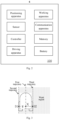
- Fig. 2 is a structural block diagram of the autonomous mobile device provided in an embodiment of the present disclosure.
- the autonomous mobile device 100 includes a positioning apparatus, a working apparatus, a sensor, a communication apparatus, a controller, a memory, a driving apparatus, and a battery.
- the positioning apparatus includes, for example, one or more of a satellite positioning system, an ultra-wideband wireless communication positioning (UWB) system, an inertial measurement unit (IMU), and a wheel speedometer.
- a position of an automatic mowing robot at a current moment can be detected by the positioning apparatus.
- the position can be expressed as its coordinates on an X axis and a Y axis of a positioning coordinate system.
- coordinates of the autonomous mobile device 100 are represented by coordinates of its movement center (X).
- the autonomous mobile device 100 includes at least one pair of driving wheels 110.
- the driving wheels are controlled by the driving apparatus to control a movement direction and a movement speed of the autonomous mobile device 100.
- the driving apparatus may include a motor and a motor controller.
- the motor controller may be, e.g., a MCU or a PLC chip.
- the working apparatus is a part of the autonomous mobile device for executing a target work.
- the autonomous mobile device 100 is a sweeping robot, and the working apparatus is a cleaning apparatus; or the autonomous mobile device 100 is a mowing robot, and the working apparatus is a mowing apparatus including a blade and a motor driving the blade.
- the sensor may include an obstacle detection sensor, which can detect an obstacle around the autonomous mobile device 100 by ultrasonic or infrared detection, for example, a pet suddenly running to the front of the autonomous mobile device.
- the communication apparatus can realize communication between the autonomous mobile device 100 and an electronic device.
- the electronic device may be, e.g., a remote controller of the autonomous mobile device 100 or a mobile terminal on which control software of the autonomous mobile device 100 runs.
- the communication apparatus is, for example, a WiFi module or a Bluetooth module.
- the controller may be implemented as, e.g., a MCU, a DSP, or an ASIC.
- a user can send a command to the autonomous mobile device 100 through the electronic device, and the controller can receive the command through a communication module to complete a corresponding operation.
- the autonomous mobile device 100 may further include, e.g., a display screen, a control button, a matching circuit board.
- the memory is configured to store, e.g., a boundary of a work region, and a traversal algorithm of the work region.
- the memory is, e.g., a non-volatile memory.
- the battery is configured to supply power for, e.g., the positioning apparatus, the working apparatus, the sensor, the communication apparatus, the controller, the memory, and the driving apparatus.
- the autonomous mobile device is required to pre-establish a map of the work region before working.
- the working mode of the autonomous mobile device 100 may include a work region planning mode and an autonomous working mode.
- the work region planning mode the user plans the work region of the autonomous mobile device 100 in a customized way.
- the autonomous mobile device 100 determines a current position using the positioning apparatus, and acquires coordinates of a next position according to the planned work path to achieve autonomous movement.
- the work region is usually defined by a boundary of the work region. In some embodiments, the boundary of the work region can be implemented by burying wires.
- the boundary of the work region may include coordinates of a series of position points.
- the autonomous mobile device is a mowing robot
- a lawn is set as a work region
- a tree in the lawn is an obstacle where the mowing robot cannot work
- ornamental flowers in the lawn are in a subregion where work is not required, so that it is necessary to set a forbidden region for the tree and the flowers.
- the boundary of the work region may be planned by driving the autonomous mobile device 100 to move and recording a series of position coordinates of the autonomous mobile device 100 during the movement.
- the position coordinates of the autonomous mobile device 100 may be obtained through the positioning apparatus.
- the user can control the autonomous mobile device 100 to move through the electronic device, thereby setting the boundary of the work region.
- the electronic device is, for example, a mobile terminal or a special remote controller of the autonomous mobile device 100.
- the electronic device can communicate with the autonomous mobile device 100 through a wireless network.
- the electronic device is installed with a control program of the autonomous mobile device, and is equipped with button options to control the movement mode of the autonomous mobile device 100 (for example, forward movement, backward movement, left turn, or right turn).
- the user controls the autonomous mobile device 100 to move by clicking different button options.
- the positioning apparatus of the autonomous mobile device 100 collects the position coordinates of the autonomous mobile device 100 at a certain frequency, and the coordinates of the autonomous mobile device 100 are characterized by the coordinates of its movement center (X).
- a set of these position coordinates constitutes a movement path of the autonomous mobile device 100, serves as the boundary of the work region, and is stored in the memory of the autonomous mobile device 100.
- a set of the coordinates of the movement center (X) stored in the memory of the autonomous mobile device 100 is referred to as a first coordinate set.
- the first coordinate set is the set of the coordinates of the autonomous mobile device 100 obtained through the positioning apparatus when the work region of the autonomous mobile device 100 is planned.
- the first coordinate set corresponds to a trajectory of the movement center (X) when the work region of the autonomous mobile device 100 is planned.
- Fig. 3 is a schematic diagram of a trajectory of the autonomous mobile device provided in an embodiment of the present disclosure when a work region of the autonomous mobile device 100 is planned. Since the autonomous mobile device 100 has a certain width (W), a movement trajectory of the autonomous mobile device 100 also has the width (W).
- the movement trajectory of the autonomous mobile device 100 includes a first trajectory, a second trajectory, and a third trajectory.
- the second trajectory corresponds to a trajectory of a first point
- the third trajectory corresponds to a trajectory of a second point
- the first trajectory corresponds to a trajectory of the movement center (X).
- the first trajectory, the second trajectory, and the third trajectory are parallel, and a distance between the first trajectory and the second trajectory is W/2.
- the first trajectory is also referred to as a first boundary
- the second trajectory is also referred to as a second boundary.
- a region between the first trajectory and the second trajectory is also a region where the autonomous mobile device 100 is required to work.
- the autonomous mobile device 100 has a certain outline and volume, the autonomous mobile device 100 cannot fully work for a work region close to a boundary, thereby affecting work coverage of the work region.
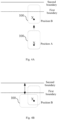
- Fig. 4A and Fig. 4B show an edging process of an autonomous mobile robot in an associated technology.
- the autonomous mobile device 100 turns at a position A in a work region, so that the autonomous mobile device 100 is perpendicular to a target segment of a boundary of the work region (i.e., a forward direction of the autonomous mobile device 100 is perpendicular to the target segment of the boundary of the work region), the autonomous mobile device 100 moves forward to a position B straightly, the autonomous mobile device 100 rotates by 90 degrees at the position B with a movement center (X) as a circle center, so that the autonomous mobile device 100 is parallel to the target segment of the boundary of the work region, and the autonomous mobile device 100 moves forward along a direction parallel to the target segment of the boundary of the work region to execute an edging work.
- the autonomous mobile device 100 has a large distance from the boundary of the work region with low work coverage.
- Fig. 5 is a flowchart of a method for controlling an autonomous mobile device provided in an embodiment of the present disclosure.
- the control method includes the following steps:
- Step S510 determining a plurality of candidate positions based on a first coordinate set.
- the first coordinate set stored in a memory of the autonomous mobile device 100 defines a work region of the autonomous mobile device 100.
- the first coordinate set is a set of coordinates of a movement center (X) of the autonomous mobile device 100 obtained in a work region planning mode.
- the plurality of candidate positions is determined in the work region of the autonomous mobile device 100 based on the first coordinate set.
- the first coordinate set corresponds to a first boundary of the work region, and the first boundary corresponds to a trajectory of the movement center (X) of the autonomous mobile device 100 in the work region planning mode.
- the first boundary includes, for example, a plurality of straight line segments.
- the plurality of candidate positions is obtained by the following approach.
- Candidate positions are set for a plurality of coordinates in the first coordinate set such that connecting lines between the candidate positions and corresponding coordinates in the first coordinate set are perpendicular to the first boundary.
- a controller of the autonomous mobile device 100 selects a plurality of coordinates from the first coordinate set, and determines coordinates of the candidate positions corresponding to the coordinates in the work region according to the selected coordinates, where connection lines between the selected coordinates and corresponding candidate positions thereof are perpendicular to the first boundary. Distances between the selected coordinates and the corresponding candidate positions thereof are identical.
- the plurality of candidate positions is obtained by the following approach.
- a second coordinate set is determined according to the first coordinate set, the second coordinate set corresponds to a second boundary, and the second boundary is parallel to the first boundary; the plurality of candidate positions in the work region is selected, and distances between each of the candidate positions and the second boundary are identical.
- the first coordinate set is the set of the coordinates of the movement center (X) of the autonomous mobile device 100 obtained in the work region planning mode. There is a constant relative position relationship between the movement center (X) of the autonomous mobile device 100 and a width definition point of the autonomous mobile device 100 corresponding to the second boundary. The relative position relationship depends on a shape and a size of the autonomous mobile device 100.
- the second coordinate set corresponding to the second boundary can be obtained according to the first coordinate set.
- the controller of the autonomous mobile device 100 selects a plurality of coordinates from the second coordinate set, and determines coordinates of the candidate positions corresponding to the coordinates in the work region according to the selected coordinates, where connection lines between the selected coordinates and corresponding candidate positions thereof are perpendicular to the second boundary. Distances between the selected coordinates and the corresponding candidate positions thereof are identical.
- Step S512 determining one of the candidate positions satisfying a safety condition for rotating the mobile device as a first position.
- the controller of the autonomous mobile device 100 performs a rotation safety check on each of the candidate positions.
- a candidate position passing the rotation safety check is a candidate position satisfying the safety condition.
- the safety condition is that the autonomous mobile device 100 can unobstructedly rotate by 360 degrees at the candidate position.
- the candidate position is represented by coordinates.
- the autonomous mobile device 100 at the candidate position means that the movement center (X) of the autonomous mobile device 100 is at the candidate position.
- the candidate position passes the rotation safety check.
- a candidate position satisfying certain conditions is selected from the candidate positions satisfying the safety condition as the first position.
- a candidate position closest to a current position of the autonomous mobile device 100 is selected from the candidate positions satisfying the safety condition as the first position.
- whether the candidate position satisfies the safety condition is ascertained by: determining a second coordinate set according to the first coordinate set, where the second coordinate set corresponds to a second boundary, and the second boundary is parallel to the first boundary; ascertaining whether a circle with the candidate position as a circle center and a predetermined length as a radius intersects with the second boundary or a boundary of a forbidden region; and determining that the candidate position satisfies the safety condition if the circle with the candidate position as the circle center and the predetermined length as the radius neither intersects with the second boundary nor intersects with the boundary of the forbidden region, and determining that the candidate position does not satisfy the safety condition if the circle with the candidate position as the circle center and the predetermined length as the radius intersects with the second boundary or the boundary of the forbidden region.
- the second coordinate set can be determined according to the first coordinate set, a movement direction of each coordinate of the autonomous mobile device 100 in the first coordinate set when the work region is planned, and one half of a width of the autonomous mobile device 100.
- the second coordinate set corresponds to coordinates of the width definition point of the autonomous mobile device when the work region of the autonomous mobile device 100 is planned.
- Fig. 6 shows a schematic diagram of determining a second boundary corresponding to a second coordinate set according to a first boundary corresponding to a first coordinate set in a memory.
- the second boundary is parallel to the first boundary, a distance between the second boundary and the first boundary is W/2, and the second boundary can be obtained by extending W/2 from the first boundary.
- Fig. 7 shows a schematic diagram on whether a candidate position satisfies a safety condition for rotating/turning the autonomous mobile device provided in an embodiment of the present disclosure.
- the second boundary includes a plurality of segments 2111-2117, and a controller determines a plurality of candidate positions. The controller ascertains whether a circle with the candidate position as a circle center and a predetermined length as a radius intersects with the second boundary or a boundary 221 of a forbidden region 220.
- Fig. 7 shows a schematic diagram on whether a candidate position satisfies a safety condition for rotating/turning the autonomous mobile device provided in an embodiment of the present disclosure.
- the second boundary includes a plurality of segments 2111-2117, and a controller determines a plurality of candidate positions. The controller ascertains whether a circle with the candidate position as a circle center and a predetermined length as a radius intersects with the second boundary or a boundary 221 of a forbidden region 220.
- a candidate position 2303 is determined based on the segment 2111 of the second boundary, a circle with the candidate position 2303 as a circle center and the predetermined length as a radius intersects with the segment 2117 of the second boundary, such that the candidate position 2303 does not satisfy the safety condition.
- a candidate position 2305 is determined based on the segment 2115 of the second boundary, a circle with the candidate position 2305 as a circle center and the predetermined length as a radius intersects with the boundary 221 of the forbidden region 220, such that the candidate position 2305 does not satisfy safety condition.
- the movement center (X) of the autonomous mobile device 100 is the circle center, a radius of a largest circumcircle of the autonomous mobile device is R, and the predetermined length is R.
- Fig. 1A and Fig. 1B show that the radius of the maximum circumscribing circle of the example autonomous mobile device 100 is R.
- Step S514 controlling the autonomous mobile device 100 to turn at the first position so that the autonomous mobile device 100 is perpendicular to a first boundary corresponding to the first coordinate set, and a tail of the autonomous mobile device is closer to the first boundary than a head of the autonomous mobile device.
- the first boundary is parallel to the second boundary, so that the autonomous mobile device after turning is also perpendicular to the second boundary.
- the autonomous mobile device 100 moves from the current position to the first position, and turns at the first position, so that the autonomous mobile device 100 is perpendicular to the first boundary, and the tail of the autonomous mobile device is closer to the first boundary than the head of the autonomous mobile device. As shown in Fig.
- the autonomous mobile device 100 performs a turning operation at the first position, and the coordinates of the movement center (X) remain unchanged during the turning operation.
- the dotted line is the autonomous mobile device 100 before the turning, and the solid line is the autonomous mobile device 100 after the turning.
- Step S516 controlling the autonomous mobile device to move backward to a second position.
- the autonomous mobile device moves backward from the first position to the second position along a straight line.
- the tail of the autonomous mobile device 100 is in front of the head of the autonomous mobile device along the movement direction.
- the geometric center (GC) is behind the movement center (X) along the movement direction.
- the second position is determined, e.g., based on the first boundary.
- the second position is selected in the work region.
- the second position is closer to the first boundary than the first position. In some embodiments, the second position is on the first boundary.
- Step S518 controlling the autonomous mobile device to turn at the second position so that the autonomous mobile device is parallel to the first boundary.
- the autonomous mobile device 100 turns by 90 degrees at the second position
- the dotted line is the autonomous mobile device 100 before the turning
- the solid line is the autonomous mobile device 100 after the turning
- the autonomous mobile device 100 after the turning is parallel to the first boundary.
- the autonomous mobile device 100 may not need the rotation safety check at the second position.
- control method further includes step S519: controlling the autonomous mobile device 100 to work.
- the autonomous mobile device 100 is, for example, a mowing robot, which moves along a direction parallel to the first boundary to execute a mowing operation.
- the autonomous mobile device 100 is, for example, a cleaning robot, which moves along a direction parallel to the first boundary to execute a cleaning operation.
- an edging process of the autonomous mobile device 100 is implemented using this control method, such that the autonomous mobile device 100 is closer to the second boundary of the work region, and can more fully process the work region between the first boundary and the second boundary, thereby improving work coverage.
- the autonomous mobile device 100 can keep close to the second boundary, thereby further improving the work coverage.
- the control method provided in the present disclosure is particularly adapted to the autonomous mobile device with the rear-mounted movement center.
- the control method may be applied to the above autonomous mobile device 100, and may be executed by a controller of the autonomous mobile device 100.
- a memory of the autonomous mobile device 100 stores a first coordinate set, and the first coordinate set includes coordinates of the autonomous mobile device when a work region of the autonomous mobile device is planned.
- control method may also be executed by an electronic device, which sends a planned path to the autonomous mobile device.
- the present disclosure further provides a computer storage medium, where the computer storage medium stores computer executable instructions, and the computer executable instructions are used for executing the above method for controlling an autonomous mobile device.
- Some embodiments of the present disclosure further provide a control apparatus of an autonomous mobile device.
- the control apparatus includes: a third module configured to control the autonomous mobile device to turn at a first position, such that the autonomous mobile device is perpendicular to a first boundary corresponding to the first coordinate set, and a tail of the autonomous mobile device is closer to the first boundary than a head of the autonomous mobile device, a fourth module configured to control the autonomous mobile device to move backward to a second position, and a fifth module configured to control the autonomous mobile device to turn at the second position so that the autonomous mobile device is parallel to the first boundary.
- control apparatus of the autonomous mobile device may further include: a first module to a fifth module.
- the first module is configured to determine a plurality of candidate positions based on the first coordinate set.
- first and second are only used for ease of description of different components or names, and cannot be understood as indicating or implying sequential relationship and relative importance or implicitly indicating the number of indicated technical features.
- features defined with “first” or “second” may explicitly or implicitly include at least one of the features.
Landscapes
- Engineering & Computer Science (AREA)
- Physics & Mathematics (AREA)
- Aviation & Aerospace Engineering (AREA)
- Radar, Positioning & Navigation (AREA)
- Remote Sensing (AREA)
- General Physics & Mathematics (AREA)
- Automation & Control Theory (AREA)
- Life Sciences & Earth Sciences (AREA)
- Environmental Sciences (AREA)
- Electromagnetism (AREA)
- Control Of Position, Course, Altitude, Or Attitude Of Moving Bodies (AREA)
- Guiding Agricultural Machines (AREA)
Description
- The present disclosure relates to the technical field of smart devices, and in particular to, a method for controlling an autonomous mobile device, an autonomous mobile device, and a computer storage medium.
- An autonomous mobile device has a mobile apparatus, a working apparatus, and a control apparatus, and can autonomously move and work within a certain range. Common autonomous mobile devices include a sweeping robot, a transfer robot, a food delivery robot, and an autonomous mobile gardening device. The autonomous mobile gardening device includes an automatic mowing robot. The automatic mowing robot can automatically mow grasses autonomously or uncontrolledly, thereby reducing time occupation of a user, and reducing labor of the user.
- The autonomous mobile device usually works within a certain work region, which is defined by a boundary. In some working modes (for example, mowing along the boundary of a lawn and safety check of a mowing robot), the autonomous mobile device (especially an autonomous mobile device with a rear-mounted movement center) is required to work in proximity to or in close proximity to the boundary of the work region. A method is required to make the autonomous mobile device work in fully close proximity to the boundary based on safety guarantee without collision.
-
EP3018548 is directed to a domestic robotic system including a robot having a payload for carrying out a domestic task within a working area. The robot's payload cover a width M when preceeding along a path. The robot can operates in a perimeter coverage mode and a area coverage mode. While in the perimeter coverage mode the robot moves generally parallel to the path of the boundary, in the area coverage mode the robot moves generally perpendicular to the path of the boundary. The robot may cross the internal area a large number of times. After completing each crossing of the internal area, the robot may then execute a turn as it approaches the edge of the internal area which is located at a given distance from the boundary and thereafter carry out a further crossing of the internal area. - In view of the above problems, embodiments of the present disclosure are presented to provide a method for controlling an autonomous mobile device, an autonomous mobile device, and a computer storage medium, to at least solve the problem that the existing autonomous mobile device fails to work in fully close proximity to the boundary.
- One or more embodiments of the present disclosure provide a method for controlling an autonomous mobile device. A memory of the autonomous mobile device stores a first coordinate set, the first coordinate set including coordinates of the autonomous mobile device when a work region of the autonomous mobile device is planned. The method for controlling an autonomous mobile device includes: determining a plurality of candidate positions based on the first coordinate set; determining one of the candidate positions satisfying a safety condition for rotating/turning the autonomous mobile device as a first position; controlling the autonomous mobile device to turn at the first position so that the autonomous mobile device is perpendicular to a first boundary corresponding to the first coordinate set, and a tail of the autonomous mobile device is closer to the first boundary than a head of the autonomous mobile device; controlling the autonomous mobile device to move backward to a second position; and controlling the autonomous mobile device to turn at the second position so that the autonomous mobile device is parallel to the first boundary.
- In some embodiments, the first coordinate set corresponds to coordinates of a movement center of the autonomous mobile device when the work region of the autonomous mobile device is planned.
- In some embodiments, the plurality of candidate positions is determined by: setting the candidate positions for a plurality of coordinates in the first coordinate set such that connecting lines between the candidate positions and corresponding coordinates in the first coordinate set are perpendicular to the first boundary.
- In some embodiments, the plurality of candidate positions is determined by: determining a second coordinate set based on the first coordinate set, where the second coordinate set corresponds to a second boundary, and the second boundary is parallel to the first boundary; and selecting the plurality of candidate positions from the work region, where distances between each of the candidate positions and the second boundary are identical.
- In some embodiments, the safety condition is that the autonomous mobile device unobstructedly rotates by 360 degrees at the candidate position.
- In some embodiments, whether the candidate position satisfies the safety condition is ascertained by: determining a second coordinate set according to the first coordinate set, where the second coordinate set corresponds to a second boundary, and the second boundary is parallel to the first boundary; ascertaining whether a circle with the candidate position as a circle center and a predetermined length as a radius intersects with the second boundary or a boundary of a forbidden region; and determining that the candidate position satisfies the safety condition if the circle with the candidate position as the circle center and the predetermined length as the radius neither intersects with the second boundary nor intersects with the boundary of the forbidden region, and determining that the candidate position does not satisfy the safety condition if the circle with the candidate position as the circle center and the predetermined length as the radius intersects with the second boundary or the boundary of the forbidden region.
- In some embodiments, the movement center of the autonomous mobile device is the circle center, a radius of a largest circumcircle of the autonomous mobile device is R, and the predetermined length is R.
- In some embodiments, the second coordinate set corresponds to coordinates of a width definition point of the autonomous mobile device when the work region of the autonomous mobile device is planned.
- In some embodiments, the first boundary is parallel to the second boundary with an equal distance therebetween.
- In some embodiments, the autonomous mobile device rotates by 90 degrees at the second position.
- In some embodiments, the method further includes: controlling the autonomous mobile device to work.
- In some embodiments, a movement center of the autonomous mobile device is behind a geometric center.
- In some embodiments, the autonomous mobile device is a mowing robot.
- According to another aspect of the present disclosure, an autonomous mobile device is provided, including a controller and a memory. The memory stores a first coordinate set, the first coordinate set corresponds to coordinates of the autonomous mobile device when a work region of the autonomous mobile device is planned, and the controller is configured to execute a method for controlling an autonomous mobile device. The method includes: controlling the autonomous mobile device to turn at the first position so that the autonomous mobile device is perpendicular to a first boundary corresponding to the first coordinate set, and a tail of the autonomous mobile device is closer to the first boundary than a head of the autonomous mobile device; controlling the autonomous mobile device to move backward to a second position; and controlling the autonomous mobile device to turn at the second position so that the autonomous mobile device is parallel to the first boundary.
- According to another aspect of the present disclosure, a computer storage medium is provided. The computer storage medium stores computer executable instructions, where the computer executable instructions are used for executing a method for controlling an autonomous mobile device. The method includes: controlling the autonomous mobile device to turn at the first position so that the autonomous mobile device is perpendicular to a first boundary corresponding to the first coordinate set, and a tail of the autonomous mobile device is closer to the first boundary than a head of the autonomous mobile device; controlling the autonomous mobile device to move backward to a second position; and controlling the autonomous mobile device to turn at the second position so that the autonomous mobile device is parallel to the first boundary.
- A method for controlling an autonomous mobile device as recited in claims 1-11 is provided, an autonomous mobile device as recited in claim 12 is provided, and a computer storage medium as recited in claim 13 is provided.
- In solutions of embodiments of the present disclosure, the autonomous mobile device is controlled to turn at a first position so that the autonomous mobile device is perpendicular to a first boundary, a tail of the autonomous mobile device is closer to the first boundary than a head of the autonomous mobile device, the autonomous mobile device moves backward to a second position, and the autonomous mobile device turns at the second position so that the autonomous mobile device is parallel to the first boundary. In this way, a distance between the autonomous mobile device after turning at the second position and a second boundary is closer, thereby improving work coverage of the autonomous mobile device in a work region. In addition, the rotation safety is checked at the first position, thereby improving the safety.
- To more clearly describe technical solutions of embodiments of the present disclosure or existing technologies, drawings to be used in the description of the embodiments or the existing technologies will be briefly introduced below. Apparently, the drawings described below are some embodiments of the present disclosure. For those of ordinary skills in the art, other drawings may also be obtained based on these drawings without making creative work.
-
Fig. 1A is an example of an autonomous mobile device provided in an embodiment of the present disclosure; -
Fig. 1B is another example of the autonomous mobile device provided in an embodiment of the present disclosure; -
Fig. 2 is a structural block diagram of the autonomous mobile device provided in an embodiment of the present disclosure; -
Fig. 3 is a schematic diagram of a trajectory of the autonomous mobile device provided in an embodiment of the present disclosure when a work region of the autonomousmobile device 100 is planned; -
Fig. 4A and Fig. 4B show an edging process of an autonomous mobile robot in an associated technology; -
Fig. 5 is a flowchart of a method for controlling an autonomous mobile device provided in an embodiment of the present disclosure; -
Fig. 6 shows a schematic diagram of determining a second boundary corresponding to a second coordinate set according to a first boundary corresponding to a first coordinate set in a memory; -
Fig. 7 shows a schematic diagram on whether a candidate position satisfies a safety condition for rotating/turning the autonomous mobile device provided in an embodiment of the present disclosure; and -
Fig. 8A-Fig. 8C show an edging process of the autonomous mobile robot provided in an embodiment of the present disclosure. - To enable those in the technical field to better understand solutions in the present disclosure, technical solutions in embodiments of the present disclosure will be clearly and completely described below with reference to drawings in the embodiments of the present disclosure. Apparently, the described embodiments are some embodiments, rather than all embodiments, of the present disclosure. All other embodiments obtained by those of ordinary skills in the art based on the embodiments of the present disclosure without making creative work are encompassed within the scope of protection of the present disclosure.
- In order to facilitate explanation and understanding, before a method for controlling an autonomous mobile device is described, a structure and a working scenario of the autonomous mobile device are briefly described below.
- The autonomous mobile device has been widely used in production and life to replace manual labor. The autonomous mobile device can autonomously move and work within a certain range. The autonomous mobile device may be a mowing robot. The mowing robot may be configured to trim a lawn to guarantee that grass height within the lawn satisfies requirements. Of course, in other embodiments, the autonomous mobile device may be other devices that can autonomously walk, such as a sweeping robot.
-
Fig. 1A is an example of an autonomous mobile device. As shown inFig. 1A , the autonomousmobile device 100 has an approximately circular shape. The autonomousmobile device 100 includes afirst driving wheel 110L, asecond driving wheel 110R, and a drivenwheel 111. The autonomousmobile device 100 has a head and a tail. Thefirst driving wheel 110L and thesecond driving wheel 110R are arranged at positions close to the tail of the autonomousmobile device 100. The drivenwheel 111 is arranged at a position close to the head of the autonomousmobile device 100. The drivenwheel 111 is, for example, a universal wheel. The autonomousmobile device 100 has a geometric center (GC) and a movement center (X). For a circular autonomous mobile device, the geometric center (GC) is located at a circle center. Thefirst driving wheel 110L and thesecond driving wheel 110R can be driven independently of each other. The autonomousmobile device 100 can make movements, such as forward movement, backward movement, turning, in-situ rotation, and climbing. The movement mode (movement direction and movement speed) of the autonomousmobile device 100 can be implemented by driving modes of thefirst driving wheel 110L and thesecond driving wheel 110R. When thefirst driving wheel 110L and thesecond driving wheel 110R rotate at a same speed, the autonomousmobile device 100 moves forward or backward. For example, thefirst driving wheel 110L and thesecond driving wheel 110R rotate clockwise at a same speed, the autonomousmobile device 100 moves forward; and when thefirst driving wheel 110L and thesecond driving wheel 110R rotate counterclockwise at a same speed, the autonomousmobile device 100 moves backward. The forward direction and the backward direction of the autonomousmobile device 100 can be preset during design. For example, when the autonomousmobile device 100 works along a planned work path, the movement direction of the autonomousmobile device 100 is the forward direction, the head of the autonomousmobile device 100 is in front, and the tail of the autonomous mobile device is behind. - The autonomous
mobile device 100 can rotate by 360 degrees in situ. The movement center (X) is a point on a rotation axis of the autonomousmobile device 100, i.e., when the autonomousmobile device 100 rotates in situ, the movement center (X) has no displacement. For example, when one of thefirst driving wheel 110L and thesecond driving wheel 110R rotates clockwise while the other rotates counterclockwise, the autonomousmobile device 100 rotates around a longitudinal axis passing through the movement center (X). - In the autonomous
mobile device 100 shown inFig. 1A , the movement center (X) is behind the geometric center (GC), i.e., the movement center (X) is in the rear of the autonomousmobile device 100. Herein, the autonomousmobile device 100 with the movement center (X) behind the geometric center (GC) is referred to as an autonomousmobile device 100 with a rear-mounted movement center.Fig. 1A further shows a maximum circumscribing circle C with the movement center (X) of the autonomousmobile device 100 as a circle center. The maximum circumscribing circle C can be determined based on the movement center (X) and a point farthest from the movement center (X) on the autonomousmobile device 100. It can be understood that when the autonomousmobile device 100 rotates around the movement center (X), the autonomousmobile device 100 will not exceed a range of the maximum circumscribing circle C.Fig. 1A further shows a radius R of the maximum circumscribing circle C. - The autonomous
mobile device 100 may further have other shape/outline. For example, the autonomousmobile device 100 may have a D-shape or an elongated D-shape, such as a rectangle or an ellipse. -
Fig. 1B is another example of the autonomous mobile device. As shown inFig. 1B , the autonomousmobile device 100 has an approximately elongated D shape. The autonomousmobile device 100 has afirst driving wheel 110L and asecond driving wheel 110R. The movement center (X) is located at a position between thefirst driving wheel 110L and thesecond driving wheel 110R, and is also located behind the geometric center (GC). The autonomousmobile device 100 shown inFig. 1B is also an autonomousmobile device 100 with a rear-mounted movement center.Fig. 1B further shows a maximum circumscribing circle C with the movement center (X) of the autonomousmobile device 100 as a circle center and a radius R of the maximum circumscribing circle C. Movement control of the autonomousmobile device 100 shown inFig. 1B is the same as that of the autonomousmobile device 100 shown inFig. 1A . -
Fig. 2 is a structural block diagram of the autonomous mobile device provided in an embodiment of the present disclosure. As shown inFig. 2 , the autonomousmobile device 100 includes a positioning apparatus, a working apparatus, a sensor, a communication apparatus, a controller, a memory, a driving apparatus, and a battery. - The positioning apparatus includes, for example, one or more of a satellite positioning system, an ultra-wideband wireless communication positioning (UWB) system, an inertial measurement unit (IMU), and a wheel speedometer. A position of an automatic mowing robot at a current moment can be detected by the positioning apparatus. The position can be expressed as its coordinates on an X axis and a Y axis of a positioning coordinate system. Specifically, coordinates of the autonomous
mobile device 100 are represented by coordinates of its movement center (X). The autonomousmobile device 100 includes at least one pair of driving wheels 110. The driving wheels are controlled by the driving apparatus to control a movement direction and a movement speed of the autonomousmobile device 100. The driving apparatus may include a motor and a motor controller. The motor controller may be, e.g., a MCU or a PLC chip. - The working apparatus is a part of the autonomous mobile device for executing a target work. For example, the autonomous
mobile device 100 is a sweeping robot, and the working apparatus is a cleaning apparatus; or the autonomousmobile device 100 is a mowing robot, and the working apparatus is a mowing apparatus including a blade and a motor driving the blade. The sensor may include an obstacle detection sensor, which can detect an obstacle around the autonomousmobile device 100 by ultrasonic or infrared detection, for example, a pet suddenly running to the front of the autonomous mobile device. - The communication apparatus can realize communication between the autonomous
mobile device 100 and an electronic device. The electronic device may be, e.g., a remote controller of the autonomousmobile device 100 or a mobile terminal on which control software of the autonomousmobile device 100 runs. The communication apparatus is, for example, a WiFi module or a Bluetooth module. The controller may be implemented as, e.g., a MCU, a DSP, or an ASIC. A user can send a command to the autonomousmobile device 100 through the electronic device, and the controller can receive the command through a communication module to complete a corresponding operation. The autonomousmobile device 100 may further include, e.g., a display screen, a control button, a matching circuit board. The memory is configured to store, e.g., a boundary of a work region, and a traversal algorithm of the work region. The memory is, e.g., a non-volatile memory. The battery is configured to supply power for, e.g., the positioning apparatus, the working apparatus, the sensor, the communication apparatus, the controller, the memory, and the driving apparatus. - Generally, the autonomous mobile device is required to pre-establish a map of the work region before working. For example, the user needs to first plan a mowing area of the mowing robot, such that the mowing robot autonomously works in the mowing area. The working mode of the autonomous
mobile device 100 may include a work region planning mode and an autonomous working mode. In the work region planning mode, the user plans the work region of the autonomousmobile device 100 in a customized way. In the autonomous working mode, the autonomousmobile device 100 determines a current position using the positioning apparatus, and acquires coordinates of a next position according to the planned work path to achieve autonomous movement. The work region is usually defined by a boundary of the work region. In some embodiments, the boundary of the work region can be implemented by burying wires. In some embodiments, the boundary of the work region may include coordinates of a series of position points. In addition, there may be an obstacle or a subregion where work is not required within the work region. For example, the autonomous mobile device is a mowing robot, a lawn is set as a work region, a tree in the lawn is an obstacle where the mowing robot cannot work, and ornamental flowers in the lawn are in a subregion where work is not required, so that it is necessary to set a forbidden region for the tree and the flowers. - In some embodiments, the boundary of the work region may be planned by driving the autonomous
mobile device 100 to move and recording a series of position coordinates of the autonomousmobile device 100 during the movement. The position coordinates of the autonomousmobile device 100 may be obtained through the positioning apparatus. For example, the user can control the autonomousmobile device 100 to move through the electronic device, thereby setting the boundary of the work region. The electronic device is, for example, a mobile terminal or a special remote controller of the autonomousmobile device 100. The electronic device can communicate with the autonomousmobile device 100 through a wireless network. The electronic device is installed with a control program of the autonomous mobile device, and is equipped with button options to control the movement mode of the autonomous mobile device 100 (for example, forward movement, backward movement, left turn, or right turn). The user controls the autonomousmobile device 100 to move by clicking different button options. The positioning apparatus of the autonomousmobile device 100 collects the position coordinates of the autonomousmobile device 100 at a certain frequency, and the coordinates of the autonomousmobile device 100 are characterized by the coordinates of its movement center (X). A set of these position coordinates constitutes a movement path of the autonomousmobile device 100, serves as the boundary of the work region, and is stored in the memory of the autonomousmobile device 100. Herein, a set of the coordinates of the movement center (X) stored in the memory of the autonomousmobile device 100 is referred to as a first coordinate set. The first coordinate set is the set of the coordinates of the autonomousmobile device 100 obtained through the positioning apparatus when the work region of the autonomousmobile device 100 is planned. The first coordinate set corresponds to a trajectory of the movement center (X) when the work region of the autonomousmobile device 100 is planned. - Since the autonomous
mobile device 100 has a certain outline and volume, when the work region of the autonomousmobile device 100 is planned, an actual trajectory of the autonomousmobile device 100 has a certain width.Fig. 3 is a schematic diagram of a trajectory of the autonomous mobile device provided in an embodiment of the present disclosure when a work region of the autonomousmobile device 100 is planned. Since the autonomousmobile device 100 has a certain width (W), a movement trajectory of the autonomousmobile device 100 also has the width (W). The movement trajectory of the autonomousmobile device 100 includes a first trajectory, a second trajectory, and a third trajectory. Since the autonomousmobile device 100 has a first width definition point D1 and a second width definition point D2 defining its width (W), the second trajectory corresponds to a trajectory of a first point, the third trajectory corresponds to a trajectory of a second point, and the first trajectory corresponds to a trajectory of the movement center (X). The first trajectory, the second trajectory, and the third trajectory are parallel, and a distance between the first trajectory and the second trajectory is W/2. Herein, the first trajectory is also referred to as a first boundary, and the second trajectory is also referred to as a second boundary. Generally, a region between the first trajectory and the second trajectory is also a region where the autonomousmobile device 100 is required to work. However, since the autonomousmobile device 100 has a certain outline and volume, the autonomousmobile device 100 cannot fully work for a work region close to a boundary, thereby affecting work coverage of the work region. -
Fig. 4A and Fig. 4B show an edging process of an autonomous mobile robot in an associated technology. As shown inFig. 4A and Fig. 4B , the autonomousmobile device 100 turns at a position A in a work region, so that the autonomousmobile device 100 is perpendicular to a target segment of a boundary of the work region (i.e., a forward direction of the autonomousmobile device 100 is perpendicular to the target segment of the boundary of the work region), the autonomousmobile device 100 moves forward to a position B straightly, the autonomousmobile device 100 rotates by 90 degrees at the position B with a movement center (X) as a circle center, so that the autonomousmobile device 100 is parallel to the target segment of the boundary of the work region, and the autonomousmobile device 100 moves forward along a direction parallel to the target segment of the boundary of the work region to execute an edging work. When approaching the boundary of the work region in this way, the autonomousmobile device 100 has a large distance from the boundary of the work region with low work coverage. -
Fig. 5 is a flowchart of a method for controlling an autonomous mobile device provided in an embodiment of the present disclosure. The control method includes the following steps: - Step S510: determining a plurality of candidate positions based on a first coordinate set. The first coordinate set stored in a memory of the autonomous
mobile device 100 defines a work region of the autonomousmobile device 100. The first coordinate set is a set of coordinates of a movement center (X) of the autonomousmobile device 100 obtained in a work region planning mode. In step S510, the plurality of candidate positions is determined in the work region of the autonomousmobile device 100 based on the first coordinate set. The first coordinate set corresponds to a first boundary of the work region, and the first boundary corresponds to a trajectory of the movement center (X) of the autonomousmobile device 100 in the work region planning mode. The first boundary includes, for example, a plurality of straight line segments. - In some embodiments, the plurality of candidate positions is obtained by the following approach. Candidate positions are set for a plurality of coordinates in the first coordinate set such that connecting lines between the candidate positions and corresponding coordinates in the first coordinate set are perpendicular to the first boundary. For example, a controller of the autonomous
mobile device 100 selects a plurality of coordinates from the first coordinate set, and determines coordinates of the candidate positions corresponding to the coordinates in the work region according to the selected coordinates, where connection lines between the selected coordinates and corresponding candidate positions thereof are perpendicular to the first boundary. Distances between the selected coordinates and the corresponding candidate positions thereof are identical. - In other embodiments, the plurality of candidate positions is obtained by the following approach. A second coordinate set is determined according to the first coordinate set, the second coordinate set corresponds to a second boundary, and the second boundary is parallel to the first boundary; the plurality of candidate positions in the work region is selected, and distances between each of the candidate positions and the second boundary are identical. The first coordinate set is the set of the coordinates of the movement center (X) of the autonomous
mobile device 100 obtained in the work region planning mode. There is a constant relative position relationship between the movement center (X) of the autonomousmobile device 100 and a width definition point of the autonomousmobile device 100 corresponding to the second boundary. The relative position relationship depends on a shape and a size of the autonomousmobile device 100. Therefore, the second coordinate set corresponding to the second boundary can be obtained according to the first coordinate set. The controller of the autonomousmobile device 100 selects a plurality of coordinates from the second coordinate set, and determines coordinates of the candidate positions corresponding to the coordinates in the work region according to the selected coordinates, where connection lines between the selected coordinates and corresponding candidate positions thereof are perpendicular to the second boundary. Distances between the selected coordinates and the corresponding candidate positions thereof are identical. - Step S512: determining one of the candidate positions satisfying a safety condition for rotating the mobile device as a first position. The controller of the autonomous
mobile device 100 performs a rotation safety check on each of the candidate positions. A candidate position passing the rotation safety check is a candidate position satisfying the safety condition. The safety condition is that the autonomousmobile device 100 can unobstructedly rotate by 360 degrees at the candidate position. The candidate position is represented by coordinates. The autonomousmobile device 100 at the candidate position means that the movement center (X) of the autonomousmobile device 100 is at the candidate position. When the autonomousmobile device 100 can unobstructedly rotate by 360 degrees at the candidate position with the movement center (X) as the circle center, the candidate position passes the rotation safety check. A candidate position satisfying certain conditions is selected from the candidate positions satisfying the safety condition as the first position. In some embodiments, a candidate position closest to a current position of the autonomousmobile device 100 is selected from the candidate positions satisfying the safety condition as the first position. - In some embodiments, whether the candidate position satisfies the safety condition is ascertained by: determining a second coordinate set according to the first coordinate set, where the second coordinate set corresponds to a second boundary, and the second boundary is parallel to the first boundary; ascertaining whether a circle with the candidate position as a circle center and a predetermined length as a radius intersects with the second boundary or a boundary of a forbidden region; and determining that the candidate position satisfies the safety condition if the circle with the candidate position as the circle center and the predetermined length as the radius neither intersects with the second boundary nor intersects with the boundary of the forbidden region, and determining that the candidate position does not satisfy the safety condition if the circle with the candidate position as the circle center and the predetermined length as the radius intersects with the second boundary or the boundary of the forbidden region.
- Specifically, the second coordinate set can be determined according to the first coordinate set, a movement direction of each coordinate of the autonomous
mobile device 100 in the first coordinate set when the work region is planned, and one half of a width of the autonomousmobile device 100. The second coordinate set corresponds to coordinates of the width definition point of the autonomous mobile device when the work region of the autonomousmobile device 100 is planned. -
Fig. 6 shows a schematic diagram of determining a second boundary corresponding to a second coordinate set according to a first boundary corresponding to a first coordinate set in a memory. As shown inFig. 6 , the second boundary is parallel to the first boundary, a distance between the second boundary and the first boundary is W/2, and the second boundary can be obtained by extending W/2 from the first boundary. -
Fig. 7 shows a schematic diagram on whether a candidate position satisfies a safety condition for rotating/turning the autonomous mobile device provided in an embodiment of the present disclosure. As shown inFig. 7 , the second boundary includes a plurality of segments 2111-2117, and a controller determines a plurality of candidate positions. The controller ascertains whether a circle with the candidate position as a circle center and a predetermined length as a radius intersects with the second boundary or aboundary 221 of a forbiddenregion 220. As shown inFig. 7 , a circle with one ofcandidate positions boundary 221 of the forbiddenregion 220, such that the candidate positions 2301, 2302, and 2304 satisfy the safety condition. Acandidate position 2303 is determined based on thesegment 2111 of the second boundary, a circle with thecandidate position 2303 as a circle center and the predetermined length as a radius intersects with thesegment 2117 of the second boundary, such that thecandidate position 2303 does not satisfy the safety condition. Acandidate position 2305 is determined based on thesegment 2115 of the second boundary, a circle with thecandidate position 2305 as a circle center and the predetermined length as a radius intersects with theboundary 221 of the forbiddenregion 220, such that thecandidate position 2305 does not satisfy safety condition. In some embodiments, the movement center (X) of the autonomousmobile device 100 is the circle center, a radius of a largest circumcircle of the autonomous mobile device is R, and the predetermined length is R.Fig. 1A and Fig. 1B show that the radius of the maximum circumscribing circle of the example autonomousmobile device 100 is R. - Step S514: controlling the autonomous
mobile device 100 to turn at the first position so that the autonomousmobile device 100 is perpendicular to a first boundary corresponding to the first coordinate set, and a tail of the autonomous mobile device is closer to the first boundary than a head of the autonomous mobile device. The first boundary is parallel to the second boundary, so that the autonomous mobile device after turning is also perpendicular to the second boundary. The autonomousmobile device 100 moves from the current position to the first position, and turns at the first position, so that the autonomousmobile device 100 is perpendicular to the first boundary, and the tail of the autonomous mobile device is closer to the first boundary than the head of the autonomous mobile device. As shown inFig. 8A , the autonomousmobile device 100 performs a turning operation at the first position, and the coordinates of the movement center (X) remain unchanged during the turning operation. The dotted line is the autonomousmobile device 100 before the turning, and the solid line is the autonomousmobile device 100 after the turning. - Step S516: controlling the autonomous mobile device to move backward to a second position. As shown in
Fig. 8B , the autonomous mobile device moves backward from the first position to the second position along a straight line. When the autonomousmobile device 100 moves backward, the tail of the autonomousmobile device 100 is in front of the head of the autonomous mobile device along the movement direction. For an autonomousmobile device 100 with a rear-mounted movement center, when the autonomousmobile device 100 moves backward, the geometric center (GC) is behind the movement center (X) along the movement direction. The second position is determined, e.g., based on the first boundary. The second position is selected in the work region. The second position is closer to the first boundary than the first position. In some embodiments, the second position is on the first boundary. - Step S518: controlling the autonomous mobile device to turn at the second position so that the autonomous mobile device is parallel to the first boundary. As shown in
Fig. 8C , the autonomousmobile device 100 turns by 90 degrees at the second position, the dotted line is the autonomousmobile device 100 before the turning, the solid line is the autonomousmobile device 100 after the turning, and the autonomousmobile device 100 after the turning is parallel to the first boundary. The autonomousmobile device 100 may not need the rotation safety check at the second position. - In some embodiments, the control method further includes step S519: controlling the autonomous
mobile device 100 to work. The autonomousmobile device 100 is, for example, a mowing robot, which moves along a direction parallel to the first boundary to execute a mowing operation. The autonomousmobile device 100 is, for example, a cleaning robot, which moves along a direction parallel to the first boundary to execute a cleaning operation. - As shown in
Fig. 8C , an edging process of the autonomousmobile device 100 is implemented using this control method, such that the autonomousmobile device 100 is closer to the second boundary of the work region, and can more fully process the work region between the first boundary and the second boundary, thereby improving work coverage. When the second position is on the first boundary, the autonomousmobile device 100 can keep close to the second boundary, thereby further improving the work coverage. It can be understood that the control method provided in the present disclosure is particularly adapted to the autonomous mobile device with the rear-mounted movement center. - The control method may be applied to the above autonomous
mobile device 100, and may be executed by a controller of the autonomousmobile device 100. A memory of the autonomousmobile device 100 stores a first coordinate set, and the first coordinate set includes coordinates of the autonomous mobile device when a work region of the autonomous mobile device is planned. - In some embodiments, the control method may also be executed by an electronic device, which sends a planned path to the autonomous mobile device.
- The present disclosure further provides a computer storage medium, where the computer storage medium stores computer executable instructions, and the computer executable instructions are used for executing the above method for controlling an autonomous mobile device.
- Some embodiments of the present disclosure further provide a control apparatus of an autonomous mobile device. The control apparatus includes: a third module configured to control the autonomous mobile device to turn at a first position, such that the autonomous mobile device is perpendicular to a first boundary corresponding to the first coordinate set, and a tail of the autonomous mobile device is closer to the first boundary than a head of the autonomous mobile device, a fourth module configured to control the autonomous mobile device to move backward to a second position, and a fifth module configured to control the autonomous mobile device to turn at the second position so that the autonomous mobile device is parallel to the first boundary.
- According to some embodiments of the present disclosure, the control apparatus of the autonomous mobile device may further include: a first module to a fifth module. The first module is configured to determine a plurality of candidate positions based on the first coordinate set.
- It should be noted that, in the description of the present disclosure, the terms "first" and "second" are only used for ease of description of different components or names, and cannot be understood as indicating or implying sequential relationship and relative importance or implicitly indicating the number of indicated technical features. Thus, features defined with "first" or "second" may explicitly or implicitly include at least one of the features.
- Unless otherwise defined, all technical terms and scientific terms used herein have the same meaning as commonly understood by those skilled in the technical field of the present disclosure. The terms used herein in the description of the present disclosure are only for the purpose of describing specific embodiments, and are not intended to limit the present disclosure.
Claims (11)
- A method for controlling an autonomous mobile device (110), wherein a memory of the autonomous mobile device (110) stores a first coordinate set, and the first coordinate set comprises coordinates of the autonomous mobile device (110) acquired when the autonomous mobile device (110) moves along a boundary of a work region during the planning of the boundary of the work region of the autonomous mobile device (110), the method being characterised by the following steps:determining (S510) a plurality of candidate positions based on the first coordinate set;determining (S512) the candidate position among the candidate positions that satisfies the condition for safe rotation of the autonomous mobile device (110) and is closest to a current position of the autonomous mobile device (110) as a first position, wherein whether the candidate position satisfies the condition for safe rotation of the autonomous mobile device (110) is determined by: determining whether a maximum circumscribing circle (C) intersects with a second boundary or a boundary of a forbidden region when the autonomous mobile device (110) is at the candidate position, wherein the maximum circumscribing circle (C) is centered on a movement center (X) of the autonomous mobile device (110) and has a radius of a distance from a point farthest from the movement center (X) on the autonomous mobile device 100 to the movement center (X), the movement center (X) is a point on a rotation axis of the autonomous mobile device (110), the second boundary is parallel to the first boundary, and at a distance of half the width of the autonomous mobile device from the first boundary; and determining that the candidate position satisfies the condition for safe rotation of the autonomous mobile device (110) when the maximum circumscribing circle (C) neither intersects with the second boundary nor intersects with the boundary of the forbidden region;controlling (S514) the autonomous mobile device (110) to turn at the first position so that the autonomous mobile device (110) is perpendicular to a first boundary corresponding to the first coordinate set, and a tail of the autonomous mobile device (110) is closer to the first boundary than a head of the autonomous mobile device (110), wherein the front portion of the autonomous mobile device when the autonomous mobile device moves in a forward direction is the head of the autonomous mobile device, the end of the autonomous mobile device opposite to the head is the tail of the autonomous mobile device, and in the forward direction the movement center (X) of the autonomous mobile device (110) is behind a geometric center (GC) of the autonomous mobile device (110);controlling (S516) the autonomous mobile device (110) to move backward to a second position, wherein the second position is closer to the first boundary than the first position and the autonomous mobile device does not trespass the second boundary when performing a 90 degree rotation at the second position; andcontrolling (S518) the autonomous mobile device (110) to turn at the second position so that the autonomous mobile device (110) is parallel to the first boundary.
- The method according to claim 1, wherein
the first coordinate set corresponds to coordinates of the movement center (X) of the autonomous mobile device (110) acquired when the autonomous mobile device (110) moves along the boundary of the work region during the planning of the boundary of the work region of the autonomous mobile device (110). - The method according to claim 1, wherein the plurality of candidate positions is determined by the following operation (a) or (b):(a) setting the candidate positions for a plurality of coordinates in the first coordinate set such that a connecting line between each of the candidate positions and its corresponding coordinate in the first coordinate set is perpendicular to the first boundary, and each of the candidate positions has equal distance from the first boundary; and(b) determining a second coordinate set based on the first coordinate set, wherein the second coordinate set corresponds to the second boundary, and the second boundary is parallel to the first boundary; and selecting the plurality of candidate positions in the work region, wherein distances between each of the candidate positions and the second boundary are identical.
- The method according to claim 1, wherein the condition for safe rotation of the autonomous mobile device (110) is that the autonomous mobile device (110) unobstructedly rotates by 360 degrees at the candidate position.
- The method according to claim 1, wherein the movement center (X) of the autonomous mobile device (110) is the circle center, a radius of a largest circumcircle of the autonomous mobile device (110) is R, and the radius of the maximum circumscribing circle (C) is R.
- The method according to claim 1, further comprising: determining a second coordinate set according to the first coordinate set, the second coordinate set corresponds to the second boundary, wherein the second coordinate set corresponds to coordinates of an end point (D1, D2) in the width direction of the autonomous mobile device (110) acquired when the autonomous mobile device (110) moves along the boundary of the work region during the planning of the boundary of the work region of the autonomous mobile device (110).
- The method according to claim 1, wherein the autonomous mobile device (110) rotates by 90 degrees at the second position.
- The method according to claim 1, wherein the method further comprises: controlling the autonomous mobile device (110) to work.
- The method according to claim 1, wherein the autonomous mobile device (110) is a mowing robot.
- An autonomous mobile device (110), comprising a controller and a memory, wherein the memory stores a first coordinate set, the first coordinate set corresponds to coordinates of the autonomous mobile device (110) when a work region of the autonomous mobile device (110) is planned, and the controller is configured to execute the method for controlling the autonomous mobile device (110) according to any one of claims 1-9.
- A computer storage medium, wherein the computer storage medium stores computer executable instructions and the computer executable instructions are used for executing the method for controlling the autonomous mobile device (110) according to any one of claims 1-9.
Applications Claiming Priority (1)
| Application Number | Priority Date | Filing Date | Title |
|---|---|---|---|
| CN202210270364.6A CN114625143B (en) | 2022-03-18 | 2022-03-18 | Self-moving device control method, self-moving device, and computer storage medium |
Publications (2)
| Publication Number | Publication Date |
|---|---|
| EP4246275A1 EP4246275A1 (en) | 2023-09-20 |
| EP4246275B1 true EP4246275B1 (en) | 2025-05-07 |
Family
ID=81901151
Family Applications (1)
| Application Number | Title | Priority Date | Filing Date |
|---|---|---|---|
| EP23162727.4A Active EP4246275B1 (en) | 2022-03-18 | 2023-03-17 | Method for controlling autonomous mobile device, autonomous mobile device, and computer storage medium |
Country Status (5)
| Country | Link |
|---|---|
| US (1) | US12481283B2 (en) |
| EP (1) | EP4246275B1 (en) |
| CN (1) | CN114625143B (en) |
| AU (1) | AU2023201680B2 (en) |
| CA (1) | CA3193225C (en) |
Families Citing this family (3)
| Publication number | Priority date | Publication date | Assignee | Title |
|---|---|---|---|---|
| CN118892020A (en) * | 2023-04-28 | 2024-11-05 | 深圳乐动机器人股份有限公司 | A lawn mowing control method and lawn mowing robot system for a lawn turning area |
| EP4715509A1 (en) * | 2023-05-16 | 2026-03-25 | Positec Technology (China) Co., Ltd. | Control method for autonomous working machine, storage medium, and autonomous working machine |
| SE547817C2 (en) * | 2024-05-24 | 2025-12-02 | Husqvarna Ab | A robotic lawn mower with enhanced cutting properties in slopes |
Family Cites Families (15)
| Publication number | Priority date | Publication date | Assignee | Title |
|---|---|---|---|---|
| US8565977B2 (en) * | 2009-06-17 | 2013-10-22 | GM Global Technology Operations LLC | Vehicle configuration for improving low speed maneuverability |
| US8706297B2 (en) | 2009-06-18 | 2014-04-22 | Michael Todd Letsky | Method for establishing a desired area of confinement for an autonomous robot and autonomous robot implementing a control system for executing the same |
| GB201306437D0 (en) * | 2013-04-09 | 2013-05-22 | F Robotics Acquisitions Ltd | Domestic robotic system and robot therfor |
| GB201419883D0 (en) * | 2014-11-07 | 2014-12-24 | F Robotics Acquisitions Ltd | Domestic robotic system and method |
| JP6701002B2 (en) * | 2016-06-23 | 2020-05-27 | 株式会社クボタ | Driving support system and work vehicle |
| CN110168465B (en) | 2017-11-16 | 2022-07-15 | 南京泉峰科技有限公司 | Smart mowing system |
| SE542915C2 (en) * | 2019-01-08 | 2020-09-15 | Husqvarna Ab | A robotic lawnmover, and methods of navigating and defining a work area for the same |
| CN111506055B (en) * | 2019-01-31 | 2024-03-08 | 苏州科瓴精密机械科技有限公司 | Walking robot and steering control method and control system thereof and walking robot manual work system |
| CN109845475B (en) * | 2019-03-01 | 2021-07-06 | 重庆火虫创新科技有限公司 | Turning control method and system of intelligent mowing robot |
| CN112230644B (en) * | 2019-07-15 | 2023-10-10 | 苏州宝时得电动工具有限公司 | Autonomous robot, and edge control method, device and storage medium thereof |
| CN113064408B (en) * | 2019-12-13 | 2023-03-10 | 苏州宝时得电动工具有限公司 | Autonomous robot, control method thereof, and computer storage medium |
| CN113296495B (en) * | 2020-02-19 | 2023-10-20 | 苏州宝时得电动工具有限公司 | Path forming method and device of self-mobile equipment and automatic working system |
| CN113348847B (en) * | 2020-03-06 | 2023-03-10 | 苏州宝时得电动工具有限公司 | Intelligent mower and mowing method thereof |
| JP7561642B2 (en) * | 2021-02-03 | 2024-10-04 | 株式会社クボタ | Farm Work Vehicle |
| JP7257433B2 (en) * | 2021-03-04 | 2023-04-13 | 三菱重工業株式会社 | Vehicle path generation method, vehicle path generation device, vehicle and program |
-
2022
- 2022-03-18 CN CN202210270364.6A patent/CN114625143B/en active Active
-
2023
- 2023-03-17 AU AU2023201680A patent/AU2023201680B2/en active Active
- 2023-03-17 US US18/185,509 patent/US12481283B2/en active Active
- 2023-03-17 EP EP23162727.4A patent/EP4246275B1/en active Active
- 2023-03-17 CA CA3193225A patent/CA3193225C/en active Active
Also Published As
| Publication number | Publication date |
|---|---|
| US20230297114A1 (en) | 2023-09-21 |
| CA3193225C (en) | 2026-04-14 |
| NZ798285A (en) | 2025-09-26 |
| US12481283B2 (en) | 2025-11-25 |
| CA3193225A1 (en) | 2023-09-18 |
| CN114625143A (en) | 2022-06-14 |
| CN114625143B (en) | 2025-09-23 |
| AU2023201680B2 (en) | 2024-07-18 |
| AU2023201680A1 (en) | 2023-10-05 |
| EP4246275A1 (en) | 2023-09-20 |
Similar Documents
| Publication | Publication Date | Title |
|---|---|---|
| CA3193225C (en) | Method for controlling autonomous mobile device, autonomous mobile device, and computer storage medium | |
| CN114937258B (en) | Control method for mowing robot, and computer storage medium | |
| CN113126613B (en) | Intelligent mowing system and autonomous mapping method thereof | |
| EP3698618B1 (en) | Smart lawn mowing system | |
| EP3158410B1 (en) | Automatic beacon position determination | |
| EP3798781B1 (en) | Automatic mower and control method | |
| CN114353801B (en) | Mobile devices and navigation methods | |
| EP3803524B1 (en) | Robotic work tool system and method for defining a working area | |
| AU2026202333A1 (en) | Improved operation for a robotic work tool | |
| CN108398944A (en) | Operating method from mobile device, self-mobile device, memory and server | |
| US20220248599A1 (en) | Lawn mower robot and method for controlling the same | |
| CN109845475B (en) | Turning control method and system of intelligent mowing robot | |
| EP3237984A1 (en) | Area exclusion for operation of a robotic vehicle | |
| WO2016103066A1 (en) | Zone control system for a robotic vehicle | |
| EP4206849B1 (en) | Autonomous mobile gardening device and method for controlling same | |
| KR102315678B1 (en) | Lawn mower robot and control method the same | |
| JP7408495B2 (en) | work robot system | |
| CN113207412B (en) | Target tracking method of visual servo mowing robot and visual servo mowing robot | |
| EP4332716A2 (en) | Mapping objects encountered by a robotic garden tool | |
| EP4137904B1 (en) | Traversal method and system, robot and readable storage medium | |
| CN112904857A (en) | Automatic guided vehicle control method and device and automatic guided vehicle | |
| EP4295660A1 (en) | Controlling movement of a robotic garden tool for docking purposes | |
| EP4678345A1 (en) | Region division method, apparatus and computer-readable storage medium | |
| JP2021197067A (en) | Operation robot | |
| EP4473821A1 (en) | Improved navigation for a robotic lawnmower system |
Legal Events
| Date | Code | Title | Description |
|---|---|---|---|
| PUAI | Public reference made under article 153(3) epc to a published international application that has entered the european phase |
Free format text: ORIGINAL CODE: 0009012 |
|
| STAA | Information on the status of an ep patent application or granted ep patent |
Free format text: STATUS: REQUEST FOR EXAMINATION WAS MADE |
|
| 17P | Request for examination filed |
Effective date: 20230317 |
|
| AK | Designated contracting states |
Kind code of ref document: A1 Designated state(s): AL AT BE BG CH CY CZ DE DK EE ES FI FR GB GR HR HU IE IS IT LI LT LU LV MC ME MK MT NL NO PL PT RO RS SE SI SK SM TR |
|
| STAA | Information on the status of an ep patent application or granted ep patent |
Free format text: STATUS: EXAMINATION IS IN PROGRESS |
|
| 17Q | First examination report despatched |
Effective date: 20240522 |
|
| REG | Reference to a national code |
Ref country code: DE Ref legal event code: R079 Free format text: PREVIOUS MAIN CLASS: G05D0001020000 Ipc: G05D0001000000 Ref document number: 602023003276 Country of ref document: DE |
|
| RIC1 | Information provided on ipc code assigned before grant |
Ipc: G05D 1/00 20060101AFI20241021BHEP |
|
| GRAP | Despatch of communication of intention to grant a patent |
Free format text: ORIGINAL CODE: EPIDOSNIGR1 |
|
| STAA | Information on the status of an ep patent application or granted ep patent |
Free format text: STATUS: GRANT OF PATENT IS INTENDED |
|
| INTG | Intention to grant announced |
Effective date: 20241202 |
|
| GRAS | Grant fee paid |
Free format text: ORIGINAL CODE: EPIDOSNIGR3 |
|
| GRAA | (expected) grant |
Free format text: ORIGINAL CODE: 0009210 |
|
| STAA | Information on the status of an ep patent application or granted ep patent |
Free format text: STATUS: THE PATENT HAS BEEN GRANTED |
|
| AK | Designated contracting states |
Kind code of ref document: B1 Designated state(s): AL AT BE BG CH CY CZ DE DK EE ES FI FR GB GR HR HU IE IS IT LI LT LU LV MC ME MK MT NL NO PL PT RO RS SE SI SK SM TR |
|
| REG | Reference to a national code |
Ref country code: GB Ref legal event code: FG4D |
|
| REG | Reference to a national code |
Ref country code: CH Ref legal event code: EP |
|
| REG | Reference to a national code |
Ref country code: DE Ref legal event code: R096 Ref document number: 602023003276 Country of ref document: DE |
|
| REG | Reference to a national code |
Ref country code: IE Ref legal event code: FG4D |
|
| REG | Reference to a national code |
Ref country code: NL Ref legal event code: MP Effective date: 20250507 |
|
| PG25 | Lapsed in a contracting state [announced via postgrant information from national office to epo] |
Ref country code: PT Free format text: LAPSE BECAUSE OF FAILURE TO SUBMIT A TRANSLATION OF THE DESCRIPTION OR TO PAY THE FEE WITHIN THE PRESCRIBED TIME-LIMIT Effective date: 20250908 Ref country code: FI Free format text: LAPSE BECAUSE OF FAILURE TO SUBMIT A TRANSLATION OF THE DESCRIPTION OR TO PAY THE FEE WITHIN THE PRESCRIBED TIME-LIMIT Effective date: 20250507 Ref country code: ES Free format text: LAPSE BECAUSE OF FAILURE TO SUBMIT A TRANSLATION OF THE DESCRIPTION OR TO PAY THE FEE WITHIN THE PRESCRIBED TIME-LIMIT Effective date: 20250507 |
|
| REG | Reference to a national code |
Ref country code: LT Ref legal event code: MG9D |
|
| PG25 | Lapsed in a contracting state [announced via postgrant information from national office to epo] |
Ref country code: NO Free format text: LAPSE BECAUSE OF FAILURE TO SUBMIT A TRANSLATION OF THE DESCRIPTION OR TO PAY THE FEE WITHIN THE PRESCRIBED TIME-LIMIT Effective date: 20250807 Ref country code: GR Free format text: LAPSE BECAUSE OF FAILURE TO SUBMIT A TRANSLATION OF THE DESCRIPTION OR TO PAY THE FEE WITHIN THE PRESCRIBED TIME-LIMIT Effective date: 20250808 |
|
| PG25 | Lapsed in a contracting state [announced via postgrant information from national office to epo] |
Ref country code: NL Free format text: LAPSE BECAUSE OF FAILURE TO SUBMIT A TRANSLATION OF THE DESCRIPTION OR TO PAY THE FEE WITHIN THE PRESCRIBED TIME-LIMIT Effective date: 20250507 Ref country code: PL Free format text: LAPSE BECAUSE OF FAILURE TO SUBMIT A TRANSLATION OF THE DESCRIPTION OR TO PAY THE FEE WITHIN THE PRESCRIBED TIME-LIMIT Effective date: 20250507 |
|
| REG | Reference to a national code |
Ref country code: AT Ref legal event code: MK05 Ref document number: 1793154 Country of ref document: AT Kind code of ref document: T Effective date: 20250507 |
|
| PG25 | Lapsed in a contracting state [announced via postgrant information from national office to epo] |
Ref country code: BG Free format text: LAPSE BECAUSE OF FAILURE TO SUBMIT A TRANSLATION OF THE DESCRIPTION OR TO PAY THE FEE WITHIN THE PRESCRIBED TIME-LIMIT Effective date: 20250507 |
|
| PG25 | Lapsed in a contracting state [announced via postgrant information from national office to epo] |
Ref country code: HR Free format text: LAPSE BECAUSE OF FAILURE TO SUBMIT A TRANSLATION OF THE DESCRIPTION OR TO PAY THE FEE WITHIN THE PRESCRIBED TIME-LIMIT Effective date: 20250507 |
|
| PG25 | Lapsed in a contracting state [announced via postgrant information from national office to epo] |
Ref country code: AT Free format text: LAPSE BECAUSE OF FAILURE TO SUBMIT A TRANSLATION OF THE DESCRIPTION OR TO PAY THE FEE WITHIN THE PRESCRIBED TIME-LIMIT Effective date: 20250507 |
|
| PG25 | Lapsed in a contracting state [announced via postgrant information from national office to epo] |
Ref country code: RS Free format text: LAPSE BECAUSE OF FAILURE TO SUBMIT A TRANSLATION OF THE DESCRIPTION OR TO PAY THE FEE WITHIN THE PRESCRIBED TIME-LIMIT Effective date: 20250807 |
|
| PG25 | Lapsed in a contracting state [announced via postgrant information from national office to epo] |
Ref country code: IS Free format text: LAPSE BECAUSE OF FAILURE TO SUBMIT A TRANSLATION OF THE DESCRIPTION OR TO PAY THE FEE WITHIN THE PRESCRIBED TIME-LIMIT Effective date: 20250907 |
|
| PG25 | Lapsed in a contracting state [announced via postgrant information from national office to epo] |
Ref country code: LV Free format text: LAPSE BECAUSE OF FAILURE TO SUBMIT A TRANSLATION OF THE DESCRIPTION OR TO PAY THE FEE WITHIN THE PRESCRIBED TIME-LIMIT Effective date: 20250507 |
|
| PG25 | Lapsed in a contracting state [announced via postgrant information from national office to epo] |
Ref country code: DK Free format text: LAPSE BECAUSE OF FAILURE TO SUBMIT A TRANSLATION OF THE DESCRIPTION OR TO PAY THE FEE WITHIN THE PRESCRIBED TIME-LIMIT Effective date: 20250507 Ref country code: SM Free format text: LAPSE BECAUSE OF FAILURE TO SUBMIT A TRANSLATION OF THE DESCRIPTION OR TO PAY THE FEE WITHIN THE PRESCRIBED TIME-LIMIT Effective date: 20250507 |
|
| PG25 | Lapsed in a contracting state [announced via postgrant information from national office to epo] |
Ref country code: CZ Free format text: LAPSE BECAUSE OF FAILURE TO SUBMIT A TRANSLATION OF THE DESCRIPTION OR TO PAY THE FEE WITHIN THE PRESCRIBED TIME-LIMIT Effective date: 20250507 |
|
| PG25 | Lapsed in a contracting state [announced via postgrant information from national office to epo] |
Ref country code: EE Free format text: LAPSE BECAUSE OF FAILURE TO SUBMIT A TRANSLATION OF THE DESCRIPTION OR TO PAY THE FEE WITHIN THE PRESCRIBED TIME-LIMIT Effective date: 20250507 |
|
| PG25 | Lapsed in a contracting state [announced via postgrant information from national office to epo] |
Ref country code: SK Free format text: LAPSE BECAUSE OF FAILURE TO SUBMIT A TRANSLATION OF THE DESCRIPTION OR TO PAY THE FEE WITHIN THE PRESCRIBED TIME-LIMIT Effective date: 20250507 |
|
| PG25 | Lapsed in a contracting state [announced via postgrant information from national office to epo] |
Ref country code: IT Free format text: LAPSE BECAUSE OF FAILURE TO SUBMIT A TRANSLATION OF THE DESCRIPTION OR TO PAY THE FEE WITHIN THE PRESCRIBED TIME-LIMIT Effective date: 20250507 |
|
| REG | Reference to a national code |
Ref country code: DE Ref legal event code: R097 Ref document number: 602023003276 Country of ref document: DE |
|
| P01 | Opt-out of the competence of the unified patent court (upc) registered |
Free format text: CASE NUMBER: UPC_APP_0000712_4246275/2026 Effective date: 20260109 |
|
| PLBE | No opposition filed within time limit |
Free format text: ORIGINAL CODE: 0009261 |
|
| STAA | Information on the status of an ep patent application or granted ep patent |
Free format text: STATUS: NO OPPOSITION FILED WITHIN TIME LIMIT |
|
| REG | Reference to a national code |
Ref country code: CH Ref legal event code: L10 Free format text: ST27 STATUS EVENT CODE: U-0-0-L10-L00 (AS PROVIDED BY THE NATIONAL OFFICE) Effective date: 20260318 |
|
| PGFP | Annual fee paid to national office [announced via postgrant information from national office to epo] |
Ref country code: DE Payment date: 20260320 Year of fee payment: 4 |
|
| 26N | No opposition filed |
Effective date: 20260210 |
|
| PGFP | Annual fee paid to national office [announced via postgrant information from national office to epo] |
Ref country code: FR Payment date: 20260105 Year of fee payment: 4 |