EP4246163A1 - Method and apparatus for determining voltage inflection point of cell in lfp battery, and medium and device - Google Patents
Method and apparatus for determining voltage inflection point of cell in lfp battery, and medium and device Download PDFInfo
- Publication number
- EP4246163A1 EP4246163A1 EP22778393.3A EP22778393A EP4246163A1 EP 4246163 A1 EP4246163 A1 EP 4246163A1 EP 22778393 A EP22778393 A EP 22778393A EP 4246163 A1 EP4246163 A1 EP 4246163A1
- Authority
- EP
- European Patent Office
- Prior art keywords
- lfp battery
- soc
- detection range
- inflection point
- charging
- Prior art date
- Legal status (The legal status is an assumption and is not a legal conclusion. Google has not performed a legal analysis and makes no representation as to the accuracy of the status listed.)
- Pending
Links
Images




Classifications
-
- G—PHYSICS
- G01—MEASURING; TESTING
- G01R—MEASURING ELECTRIC VARIABLES; MEASURING MAGNETIC VARIABLES
- G01R31/00—Arrangements for testing electric properties; Arrangements for locating electric faults; Arrangements for electrical testing characterised by what is being tested not provided for elsewhere
- G01R31/36—Arrangements for testing, measuring or monitoring the electrical condition of accumulators or electric batteries, e.g. capacity or state of charge [SoC]
- G01R31/382—Arrangements for monitoring battery or accumulator variables, e.g. SoC
-
- H—ELECTRICITY
- H01—ELECTRIC ELEMENTS
- H01M—PROCESSES OR MEANS, e.g. BATTERIES, FOR THE DIRECT CONVERSION OF CHEMICAL ENERGY INTO ELECTRICAL ENERGY
- H01M10/00—Secondary cells; Manufacture thereof
- H01M10/42—Methods or arrangements for servicing or maintenance of secondary cells or secondary half-cells
- H01M10/4285—Testing apparatus
-
- G—PHYSICS
- G01—MEASURING; TESTING
- G01R—MEASURING ELECTRIC VARIABLES; MEASURING MAGNETIC VARIABLES
- G01R19/00—Arrangements for measuring currents or voltages or for indicating presence or sign thereof
- G01R19/165—Indicating that current or voltage is either above or below a predetermined value or within or outside a predetermined range of values
- G01R19/16566—Circuits and arrangements for comparing voltage or current with one or several thresholds and for indicating the result not covered by subgroups G01R19/16504, G01R19/16528, G01R19/16533
- G01R19/16571—Circuits and arrangements for comparing voltage or current with one or several thresholds and for indicating the result not covered by subgroups G01R19/16504, G01R19/16528, G01R19/16533 comparing AC or DC current with one threshold, e.g. load current, over-current, surge current or fault current
-
- G—PHYSICS
- G01—MEASURING; TESTING
- G01R—MEASURING ELECTRIC VARIABLES; MEASURING MAGNETIC VARIABLES
- G01R31/00—Arrangements for testing electric properties; Arrangements for locating electric faults; Arrangements for electrical testing characterised by what is being tested not provided for elsewhere
- G01R31/36—Arrangements for testing, measuring or monitoring the electrical condition of accumulators or electric batteries, e.g. capacity or state of charge [SoC]
- G01R31/367—Software therefor, e.g. for battery testing using modelling or look-up tables
-
- G—PHYSICS
- G01—MEASURING; TESTING
- G01R—MEASURING ELECTRIC VARIABLES; MEASURING MAGNETIC VARIABLES
- G01R31/00—Arrangements for testing electric properties; Arrangements for locating electric faults; Arrangements for electrical testing characterised by what is being tested not provided for elsewhere
- G01R31/36—Arrangements for testing, measuring or monitoring the electrical condition of accumulators or electric batteries, e.g. capacity or state of charge [SoC]
- G01R31/378—Arrangements for testing, measuring or monitoring the electrical condition of accumulators or electric batteries, e.g. capacity or state of charge [SoC] specially adapted for the type of battery or accumulator
- G01R31/379—Arrangements for testing, measuring or monitoring the electrical condition of accumulators or electric batteries, e.g. capacity or state of charge [SoC] specially adapted for the type of battery or accumulator for lead-acid batteries
-
- G—PHYSICS
- G01—MEASURING; TESTING
- G01R—MEASURING ELECTRIC VARIABLES; MEASURING MAGNETIC VARIABLES
- G01R31/00—Arrangements for testing electric properties; Arrangements for locating electric faults; Arrangements for electrical testing characterised by what is being tested not provided for elsewhere
- G01R31/36—Arrangements for testing, measuring or monitoring the electrical condition of accumulators or electric batteries, e.g. capacity or state of charge [SoC]
- G01R31/382—Arrangements for monitoring battery or accumulator variables, e.g. SoC
- G01R31/3842—Arrangements for monitoring battery or accumulator variables, e.g. SoC combining voltage and current measurements
-
- G—PHYSICS
- G01—MEASURING; TESTING
- G01R—MEASURING ELECTRIC VARIABLES; MEASURING MAGNETIC VARIABLES
- G01R31/00—Arrangements for testing electric properties; Arrangements for locating electric faults; Arrangements for electrical testing characterised by what is being tested not provided for elsewhere
- G01R31/36—Arrangements for testing, measuring or monitoring the electrical condition of accumulators or electric batteries, e.g. capacity or state of charge [SoC]
- G01R31/385—Arrangements for measuring battery or accumulator variables
-
- G—PHYSICS
- G01—MEASURING; TESTING
- G01R—MEASURING ELECTRIC VARIABLES; MEASURING MAGNETIC VARIABLES
- G01R31/00—Arrangements for testing electric properties; Arrangements for locating electric faults; Arrangements for electrical testing characterised by what is being tested not provided for elsewhere
- G01R31/36—Arrangements for testing, measuring or monitoring the electrical condition of accumulators or electric batteries, e.g. capacity or state of charge [SoC]
- G01R31/392—Determining battery ageing or deterioration, e.g. state of health
-
- G—PHYSICS
- G01—MEASURING; TESTING
- G01R—MEASURING ELECTRIC VARIABLES; MEASURING MAGNETIC VARIABLES
- G01R31/00—Arrangements for testing electric properties; Arrangements for locating electric faults; Arrangements for electrical testing characterised by what is being tested not provided for elsewhere
- G01R31/36—Arrangements for testing, measuring or monitoring the electrical condition of accumulators or electric batteries, e.g. capacity or state of charge [SoC]
- G01R31/396—Acquisition or processing of data for testing or for monitoring individual cells or groups of cells within a battery
-
- H—ELECTRICITY
- H01—ELECTRIC ELEMENTS
- H01M—PROCESSES OR MEANS, e.g. BATTERIES, FOR THE DIRECT CONVERSION OF CHEMICAL ENERGY INTO ELECTRICAL ENERGY
- H01M10/00—Secondary cells; Manufacture thereof
- H01M10/05—Accumulators with non-aqueous electrolyte
- H01M10/052—Li-accumulators
-
- H—ELECTRICITY
- H01—ELECTRIC ELEMENTS
- H01M—PROCESSES OR MEANS, e.g. BATTERIES, FOR THE DIRECT CONVERSION OF CHEMICAL ENERGY INTO ELECTRICAL ENERGY
- H01M10/00—Secondary cells; Manufacture thereof
- H01M10/05—Accumulators with non-aqueous electrolyte
- H01M10/052—Li-accumulators
- H01M10/0525—Rocking-chair batteries, i.e. batteries with lithium insertion or intercalation in both electrodes; Lithium-ion batteries
-
- H—ELECTRICITY
- H01—ELECTRIC ELEMENTS
- H01M—PROCESSES OR MEANS, e.g. BATTERIES, FOR THE DIRECT CONVERSION OF CHEMICAL ENERGY INTO ELECTRICAL ENERGY
- H01M10/00—Secondary cells; Manufacture thereof
- H01M10/42—Methods or arrangements for servicing or maintenance of secondary cells or secondary half-cells
-
- H—ELECTRICITY
- H01—ELECTRIC ELEMENTS
- H01M—PROCESSES OR MEANS, e.g. BATTERIES, FOR THE DIRECT CONVERSION OF CHEMICAL ENERGY INTO ELECTRICAL ENERGY
- H01M10/00—Secondary cells; Manufacture thereof
- H01M10/42—Methods or arrangements for servicing or maintenance of secondary cells or secondary half-cells
- H01M10/44—Methods for charging or discharging
-
- H—ELECTRICITY
- H01—ELECTRIC ELEMENTS
- H01M—PROCESSES OR MEANS, e.g. BATTERIES, FOR THE DIRECT CONVERSION OF CHEMICAL ENERGY INTO ELECTRICAL ENERGY
- H01M10/00—Secondary cells; Manufacture thereof
- H01M10/42—Methods or arrangements for servicing or maintenance of secondary cells or secondary half-cells
- H01M10/48—Accumulators combined with arrangements for measuring, testing or indicating the condition of cells, e.g. the level or density of the electrolyte
-
- H—ELECTRICITY
- H01—ELECTRIC ELEMENTS
- H01M—PROCESSES OR MEANS, e.g. BATTERIES, FOR THE DIRECT CONVERSION OF CHEMICAL ENERGY INTO ELECTRICAL ENERGY
- H01M4/00—Electrodes
- H01M4/02—Electrodes composed of, or comprising, active material
- H01M4/36—Selection of substances as active materials, active masses, active liquids
- H01M4/58—Selection of substances as active materials, active masses, active liquids of inorganic compounds other than oxides or hydroxides, e.g. sulfides, selenides, tellurides, halogenides or LiCoFy; of polyanionic structures, e.g. phosphates, silicates or borates
- H01M4/5825—Oxygenated metallic salts or polyanionic structures, e.g. borates, phosphates, silicates, olivines
-
- H—ELECTRICITY
- H02—GENERATION; CONVERSION OR DISTRIBUTION OF ELECTRIC POWER
- H02J—ELECTRIC POWER NETWORKS; CIRCUIT ARRANGEMENTS OR SYSTEMS FOR SUPPLYING OR DISTRIBUTING ELECTRIC POWER; SYSTEMS FOR STORING ELECTRIC ENERGY
- H02J7/00—Circuit arrangements for charging or discharging batteries or for supplying loads from batteries
- H02J7/80—Circuit arrangements for charging or discharging batteries or for supplying loads from batteries including monitoring or indicating arrangements
-
- H—ELECTRICITY
- H02—GENERATION; CONVERSION OR DISTRIBUTION OF ELECTRIC POWER
- H02J—ELECTRIC POWER NETWORKS; CIRCUIT ARRANGEMENTS OR SYSTEMS FOR SUPPLYING OR DISTRIBUTING ELECTRIC POWER; SYSTEMS FOR STORING ELECTRIC ENERGY
- H02J7/00—Circuit arrangements for charging or discharging batteries or for supplying loads from batteries
- H02J7/80—Circuit arrangements for charging or discharging batteries or for supplying loads from batteries including monitoring or indicating arrangements
- H02J7/82—Control of state of charge [SOC]
-
- H—ELECTRICITY
- H02—GENERATION; CONVERSION OR DISTRIBUTION OF ELECTRIC POWER
- H02J—ELECTRIC POWER NETWORKS; CIRCUIT ARRANGEMENTS OR SYSTEMS FOR SUPPLYING OR DISTRIBUTING ELECTRIC POWER; SYSTEMS FOR STORING ELECTRIC ENERGY
- H02J7/00—Circuit arrangements for charging or discharging batteries or for supplying loads from batteries
- H02J7/80—Circuit arrangements for charging or discharging batteries or for supplying loads from batteries including monitoring or indicating arrangements
- H02J7/84—Control of state of health [SOH]
-
- H—ELECTRICITY
- H02—GENERATION; CONVERSION OR DISTRIBUTION OF ELECTRIC POWER
- H02J—ELECTRIC POWER NETWORKS; CIRCUIT ARRANGEMENTS OR SYSTEMS FOR SUPPLYING OR DISTRIBUTING ELECTRIC POWER; SYSTEMS FOR STORING ELECTRIC ENERGY
- H02J7/00—Circuit arrangements for charging or discharging batteries or for supplying loads from batteries
- H02J7/90—Regulation of charging or discharging current or voltage
- H02J7/94—Regulation of charging or discharging current or voltage in response to battery current
- H02J7/947—Regulation of charging or discharging current or voltage in response to battery current in response to integrated charge or discharge current
-
- G—PHYSICS
- G01—MEASURING; TESTING
- G01R—MEASURING ELECTRIC VARIABLES; MEASURING MAGNETIC VARIABLES
- G01R31/00—Arrangements for testing electric properties; Arrangements for locating electric faults; Arrangements for electrical testing characterised by what is being tested not provided for elsewhere
- G01R31/36—Arrangements for testing, measuring or monitoring the electrical condition of accumulators or electric batteries, e.g. capacity or state of charge [SoC]
- G01R31/378—Arrangements for testing, measuring or monitoring the electrical condition of accumulators or electric batteries, e.g. capacity or state of charge [SoC] specially adapted for the type of battery or accumulator
-
- Y—GENERAL TAGGING OF NEW TECHNOLOGICAL DEVELOPMENTS; GENERAL TAGGING OF CROSS-SECTIONAL TECHNOLOGIES SPANNING OVER SEVERAL SECTIONS OF THE IPC; TECHNICAL SUBJECTS COVERED BY FORMER USPC CROSS-REFERENCE ART COLLECTIONS [XRACs] AND DIGESTS
- Y02—TECHNOLOGIES OR APPLICATIONS FOR MITIGATION OR ADAPTATION AGAINST CLIMATE CHANGE
- Y02E—REDUCTION OF GREENHOUSE GAS [GHG] EMISSIONS, RELATED TO ENERGY GENERATION, TRANSMISSION OR DISTRIBUTION
- Y02E60/00—Enabling technologies; Technologies with a potential or indirect contribution to GHG emissions mitigation
- Y02E60/10—Energy storage using batteries
Definitions
- the present disclosure relates to the technical field of automatic control in a power battery, and particularly to a method, apparatus, medium and device for determining a voltage inflection point of a cell core in a LFP battery.
- the voltage inflection point in a lithium-ion battery is the phenomenon of an inflection point in the voltage-charge characteristics curve during charging and discharging. This phenomenon is caused by the electrochemical properties of the battery itself, and the characteristics of the inflection point are affected by factors such as the battery temperature, State of health (SOH), and charge and discharge current or the like of the battery.
- SOH State of health
- the voltage inflection point of a lithium-ion battery has wide applications in estimation of State of health (SOH) of a power battery, calculation of the target equalized charge of a battery module or the like.
- the voltage differential curve presents apparent characteristic peaks, which enables easy detection of the voltage inflection point. As the current increases, the characteristic peaks gradually disappear. In the high current fast charging mode, however, it is difficult to detect the voltage inflection point of the battery, and application of the above functions based on the voltage inflection point cannot be achieved. For example, for an operating vehicle adopting the fast charging mode for charging for a prolonged time period, this causes problems of incapability of timely update of the SOH of the battery, prolonged incapability of enabling battery equalization or the like.
- the present disclosure provides a method for determining a voltage inflection point of a cell core in a LFP battery, including:
- the method before charging the LFP battery with the first current value and monitoring the State of charge (SOC) of the LFP battery, the method further includes:
- the determining the detection range according to the SOC of the LFP battery includes:
- the method further includes: updating the detection range according to the detected voltage inflection point of the various cell cores.
- the updating the detection range according to the detected voltage inflection point of the various cell cores includes:
- the updating the detection range according to the determined SOC of the LFP battery includes:
- the updating the detection range according to the detected voltage inflection point of the various cell cores includes:
- the present disclosure provides an apparatus for determining a voltage inflection point in a LFP battery, the apparatus including:
- the present disclosure further provides a computer-readable storage medium having a computer program stored thereon which, when executed by a processor, implements the steps of the above method provided by the present disclosure.
- the present disclosure further provides an electronic device, including:
- the charging current can be regulated within a predetermined detection range in such a manner that it is controlled in a targeted manner so that charging is done with a low current to detect the voltage inflection point of the cell cores within this detection range and so that charging is done according to the original high current strategy in the remaining range.
- the SOH of the LFP battery can be updated in time and the battery can be equalized in time.
- FIG. 1 is a schematic graph showing that the charging voltage varies with the charged capacity of a lithium-ion battery during charging of the battery.
- the horizontal axis represents the charged capacity of the battery in Ah and the vertical axis represents the charging voltage in V.
- FIG. 1 shows the curve a for the charging current of 0.5C and the curve b for the charging current of 0.1C.
- FIG. 2 is a schematic graph showing the voltage differential curve during charging of a lithium-ion battery.
- the horizontal axis represents the charged capacity of the battery and the vertical axis represents the voltage differential (dV/dQ).
- FIG. 2 shows the curve A for the charging current of 0.5C and the curve B for the charging current of 0.1C.
- the dotted circle in the curve b corresponds to the dotted circle in the curve B and represents the voltage inflection point of this lithium battery, which is at about 80Ah. It can be seen that the curve B for the low charging current has an apparent voltage inflection point, whereas the curve A for the high charging current has no voltage inflection point. It can be seen that in the high current fast charging mode, it is difficult to detect the voltage inflection point of the lithium-ion battery.
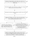
- FIG. 3 is a flow chart of a method for determining a voltage inflection point of a cell core in a LFP battery according to an exemplary embodiment. As shown in FIG. 3 , the method may include the following steps.
- Step S11 the LiFePO4 (LFP) battery is charged with a first current value and the State of charge (SOC) of the LFP battery is monitored.
- the first current value is greater than a predetermined threshold of current.
- Step S12 if the SOC of the LFP battery is outside a predetermined detection range, the LFP battery is controlled and charged with the first current value.
- Step S13 if the SOC of the LFP battery is within the detection range, the LFP battery is controlled and charged with the second current value.
- the second current value is less than the predetermined threshold of current.
- Step S14 the voltage inflection point of various cell cores in the LFP battery is detected according to parameter information of the various cell cores in the LFP battery in the process of charging where the SOC of the LFP battery is within the detection range.
- the present disclosure is applicable to a LFP battery.
- the current and voltage of the battery can be detected in real time and the SOC of the LFP battery can be calculated.
- the method for determining SOC is well known to those skilled in the art and thus shall not be detailed herein.
- the detection range may be determined in advance. Specifically, the voltage inflection point of various cell cores in the LFP battery may be detected before the end of the production line of the vehicle and the SOC of the battery is determined according to the voltage inflection point of the various cell cores. An upper limit and a lower limit for the detection range are set near the SOC of this battery, and the determined detection range is stored.
- the first current value may represent, for example, a charging current obtained according to the MAP table of the charging strategy for this fast charging mode.
- the LFP battery is charged with the first current value, i.e., the LFP battery is normally charged in the fast charging mode.
- the second current value may be a charging current value, causing the charging voltage to have an apparent inflection point.
- the voltage inflection point of each cell core is detected according to the parameter information of this cell core respectively.
- the method for detecting the voltage inflection point is well known to those skilled in the art and thus shall not be detailed herein.
- the present solution in the process of charging the LFP battery with a high current (of the first current value), in some SOC ranges (detection range) a low charging current (of the second current value) is used and the voltage inflection point of the cell cores is detected, and in other SOC ranges, the charging strategy of original high current (of the first current value) charging is maintained.
- BMS Battery Management System
- the charging current is regulated within a predetermined detection range in such a manner that it is controlled in a targeted manner so that charging is done with a low current to detect the voltage inflection point of the cell cores within this detection range and so that charging is done according to the original high current strategy in the remaining range.
- the SOH of the LFP battery can be updated in time and the battery can be equalized in time.
- FIG. 4 is a flow chart of a method for determining a voltage inflection point of a cell core in a LFP battery according to another exemplary embodiment. As shown in FIG. 4 , on the basis of FIG. 3 , before the step of charging the LFP battery with the first current value and monitoring the SOC of the LFP battery (Step S11), this method may further include the following steps.
- Step S01 while charging the LFP battery with the second current value, the voltage inflection point of various cell cores in the LFP battery is detected.
- Step S02 the SOC of the LFP battery is determined according to the voltage inflection point of the various cell cores.
- the SOC of the LFP battery may be determined at one time according to the voltage inflection point of each cell core, and then the final SOC of the LFP battery is determined according to the SOCs of the LFP battery determined at multiple times (for example, by averaging them).
- Step S03 the detection range is determined according to the SOC of the LFP battery.
- an off-line low current charging test can be performed on a power battery sample before the end of the production line of the vehicle to determine the SOC of the battery at the time when the voltage inflection point occurs, and a detection range is determined according to this SOC.
- the detection range determined in this way is relatively accurate. Therefore, it is very easy to detect the voltage inflection point of the cell core with the method of FIG. 3 during high current charging of the real vehicle.
- the step of determining a detection range according to the SOC of the LFP battery may include:
- the SOC of the battery as determined according to the voltage inflection point of the cell cores detected in the slow charging mode is extended upward and downward respectively by W to obtain the detection range.
- the SOC of the battery as determined according to the voltage inflection point detected in the slow charging mode lies at the midpoint of the detection range, which provides reasonable setting of the detection range, so that it is easy to detect the voltage inflection point with the method of FIG. 3 during high current charging of the real vehicle.
- the method may further include: updating the detection range according to the detected voltage inflection point of the various cell cores.
- the voltage inflection point detected in the present charging is the up-to-date characteristic value of the various cell cores that characterizes the up-to-date state of the various cell cores. Therefore, based on this, the detection range can be updated and the detection range can be dynamically adjusted so that in the next high current charging, detection of the voltage inflection point can be more reliable. Therefore, the voltage inflection point of the cell cores can be detected in real time despite gradual aging of the battery.
- the updating the detection range according to the detected voltage inflection point of the various cell cores may include the following steps. If the voltage inflection point of the cell cores in the LFP battery has been detected, the SOC of the LFP battery is determined according to the voltage inflection point of the various cell cores. The detection range is updated according to the determined SOC of the LFP battery.
- the SOC of the LFP battery may be determined at one time according to the voltage inflection point of each cell core, and then the final SOC of the LFP battery is determined according to the SOCs of the LFP battery determined at multiple times. Then an updated detection range is determined according to the SOC of the LFP battery. As the detection range is updated on the basis of the up-to-date SOC of the LFP battery, detection of the voltage inflection point is more reliable during the next high current charging.
- the range containing this SOC can be taken as the updated detection range.
- the value of the upper limit of the updated detection range may be this SOC plus the predetermined constant a
- the value of the lower limit of the updated detection range may be this SOC minus the constant b
- the constant a may not be equal to the constant b
- the updating the detection range according to the determined SOC of the LFP battery may include:
- the conception of the formula (2) is similar to that of the formula (1). That is, the SOC of the battery as determined according to the voltage inflection point detected in the present charging is extended upward and downward respectively by P to obtain the detection range updated after the present charging. As such, the SOC of the battery as determined according to the voltage inflection point of the cell core detected in the present charging lies at the midpoint of the detection range, which provides reasonable setting of the detection range, so that it is easy to detect the voltage inflection point with the method of FIG. 3 during high current charging of the real vehicle.
- the detection range applied for the present charging is extended upward and downward by the same width, so that in the next charging, it is possible to detect a voltage inflection point for the cell cores.
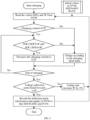
- FIG. 5 is a flow chart of a method for determining a voltage inflection point of a cell core in a LFP battery according to yet another exemplary embodiment.
- the method for controlling charging of a LFP battery may include the following steps.
- FIG. 6 is a schematic view showing charging current regulation for a LFP battery according to an exemplary embodiment.
- the horizontal axis represents the charging duration.
- the current is regulated in 55%-65% of the range (detection range) and corresponds to a low charging current in the current curve, and corresponds to the segment of voltage curve in the corresponding time period.
- the point represented by an asterisk is the voltage inflection point, which is an apparent inflection point in the voltage differential curve.
- FIG. 7 is a block diagram of an apparatus for determining a voltage inflection point of a cell core in a LFP battery according to an exemplary embodiment.
- the apparatus 700 for determining a voltage inflection point of a cell core in a LFP battery may include a monitoring module 701, a first control module 702, a second control module 703 and a first detection module 704.
- the monitoring module 701 is configured to charge the LFP battery with a first current value and monitor the State of charge (SOC) of the LFP battery.
- the first current value is greater than a predetermined threshold of current.
- the first control module 702 is configured to control and charge the LFP battery with the first current value if the SOC of the LFP battery is outside the predetermined detection range.
- the second control module 703 is configured to control and charge the LFP battery with the second current value if the SOC of the LFP battery is within the detection range.
- the second current value is less than the predetermined threshold of current.
- the first detection module 704 is configured to detect the voltage inflection point of various cell cores in the LFP battery according to parameter information of the various cell cores in the LFP battery in the process of charging where the SOC of the LFP battery is within the detection range.
- the apparatus 700 may further include a second detection module, a first determination module and a second determination module.
- the second detection module is configured to detect the voltage inflection point of various cell cores in the LFP battery while charging the LFP battery with the second current value.
- the first determination module is configured to determine the SOC of the LFP battery according to the voltage inflection point of various cell cores.
- the second determination module is configured to determine the detection range according to the SOC of the LFP battery.
- SOC 0 is the SOC of the LFP battery determined according to the voltage inflection point of the various cell cores during charging of the LFP battery with the second current value
- Q is the detection range and W is a predetermined constant, and 0 ⁇ W ⁇ 1.
- the apparatus 700 may further include an update module.
- the update module is configured to update the detection range according to the detected voltage inflection point of the various cell cores.
- the update module includes a determination submodule and a first update submodule.
- the determination submodule is configured to determine the SOC of the LFP battery according to the voltage inflection point of various cell cores if the voltage inflection point of the cell cores in the LFP battery has been detected.
- the first update submodule is configured to update the detection range according to the determined SOC of the LFP battery.
- SOC 1 is the SOC of the LFP battery determined according to the detected voltage inflection point of the various cell cores in the present charging
- Q 1 is the detection range updated after the present charging
- P is a predetermined constant, and 0 ⁇ P ⁇ 1.
- the update module may include a second update submodule.
- the charging current can be regulated within a predetermined detection range in such a manner that it is controlled in a targeted manner so that charging is done with a low current to detect the voltage inflection point of the cell cores within this detection range and so that charging is done according to the original high current strategy in the remaining range.
- the SOH of the LFP battery can be updated in time and the battery can be equalized in time.
- the present disclosure further provides a computer-readable storage medium having a computer program stored thereon which, when executed by a processor, implements the steps of the above method provided by the present disclosure.
- the present disclosure further provides an electronic device which includes a memory and a processor.
- the memory has a computer program stored thereon.
- the processor is configured to execute the computer program in the memory to implement the steps of the above method provided by the present disclosure.
- the present disclosure further provides a vehicle.
- the vehicle includes a LFP battery and an apparatus 700 for determining a voltage inflection point of a cell core in a LFP battery described above that is provided by the present disclosure.
Landscapes
- Engineering & Computer Science (AREA)
- Physics & Mathematics (AREA)
- General Physics & Mathematics (AREA)
- Chemical & Material Sciences (AREA)
- Chemical Kinetics & Catalysis (AREA)
- Electrochemistry (AREA)
- General Chemical & Material Sciences (AREA)
- Manufacturing & Machinery (AREA)
- Power Engineering (AREA)
- Materials Engineering (AREA)
- Inorganic Chemistry (AREA)
- Crystallography & Structural Chemistry (AREA)
- Secondary Cells (AREA)
- Charge And Discharge Circuits For Batteries Or The Like (AREA)
- Battery Electrode And Active Subsutance (AREA)
Abstract
Description
- The present disclosure claims priority to
Chinese Patent Application 202110351934.X filed on March 31, 2021 - The present disclosure relates to the technical field of automatic control in a power battery, and particularly to a method, apparatus, medium and device for determining a voltage inflection point of a cell core in a LFP battery.
- The voltage inflection point in a lithium-ion battery is the phenomenon of an inflection point in the voltage-charge characteristics curve during charging and discharging. This phenomenon is caused by the electrochemical properties of the battery itself, and the characteristics of the inflection point are affected by factors such as the battery temperature, State of health (SOH), and charge and discharge current or the like of the battery. The voltage inflection point of a lithium-ion battery has wide applications in estimation of State of health (SOH) of a power battery, calculation of the target equalized charge of a battery module or the like.
- In the AC pile low current charging mode, the voltage differential curve presents apparent characteristic peaks, which enables easy detection of the voltage inflection point. As the current increases, the characteristic peaks gradually disappear. In the high current fast charging mode, however, it is difficult to detect the voltage inflection point of the battery, and application of the above functions based on the voltage inflection point cannot be achieved. For example, for an operating vehicle adopting the fast charging mode for charging for a prolonged time period, this causes problems of incapability of timely update of the SOH of the battery, prolonged incapability of enabling battery equalization or the like.
- It is an objective of the present disclosure to provide a method, apparatus, medium and device for determining a voltage inflection point of a cell core in a LFP battery that can identify the voltage inflection point during charging.
- In order to achieve the above objective, the present disclosure provides a method for determining a voltage inflection point of a cell core in a LFP battery, including:
- charging the LFP battery with a first current value and monitoring the State of charge (SOC) of the LFP battery, the first current value being greater than a predetermined threshold of current;
- if the SOC of the LFP battery is outside a predetermined detection range, the LFP battery is controlled and charged with the first current value;
- if the SOC of the LFP battery is within the detection range, the LFP battery is controlled and charged with a second current value, the second current value being less than the predetermined threshold of current; and
- detecting the voltage inflection point of various cell cores in the LFP battery according to parameter information of the various cell cores in the LFP battery in the process of charging where the SOC of the LFP battery is within the detection range.
- Optionally, before charging the LFP battery with the first current value and monitoring the State of charge (SOC) of the LFP battery, the method further includes:
- detecting the voltage inflection point of various cell cores in the LFP battery while charging the LFP battery with the second current value;
- determining the SOC of the LFP battery according to the voltage inflection point of the various cell cores; and
- determining the detection range according to the SOC of the LFP battery.
- Optionally, the determining the detection range according to the SOC of the LFP battery includes:
- determining the detection range by

- where SOC 0 is the SOC of the LFP battery determined according to the voltage inflection point of the various cell cores during charging of the LFP battery with the second current value, Q is the detection range and W is a predetermined constant, and 0<W<1.
- Optionally, after detecting the voltage inflection point of various cell cores in the LFP battery according to parameter information of the various cell cores in the LFP battery in the process of charging where the SOC of the LFP battery is within the detection range, the method further includes:
updating the detection range according to the detected voltage inflection point of the various cell cores. - Optionally, the updating the detection range according to the detected voltage inflection point of the various cell cores includes:
- if the voltage inflection point of the cell cores in the LFP battery has been detected, determining the SOC of the LFP battery according to the voltage inflection point of the various cell cores; and
- updating the detection range according to the determined SOC of the LFP battery.
- Optionally, the updating the detection range according to the determined SOC of the LFP battery includes:
- updating the detection range by

- where SOC 1 is the SOC of the LFP battery determined according to the detected voltage inflection point of the various cell cores in the present charging, Q 1 is the detection range updated after the present charging, and P is a predetermined constant, and 0<P<1.
- Optionally, the updating the detection range according to the detected voltage inflection point of the various cell cores includes:
- if it is detected that no voltage inflection point has been detected for any of the cell cores in the LFP battery, updating the detection range to:

- where Q 2 is the detection range updated after the present charging, m is a predetermined constant, and 0<m<1, and M, N are respectively a lower limit and an upper limit of the detection range applied for the present charging.
- The present disclosure provides an apparatus for determining a voltage inflection point in a LFP battery, the apparatus including:
- a monitoring module configured to charge the LFP battery with a first current value and monitor the State of charge (SOC) of the LFP battery, the first current value being greater than a predetermined threshold of current;
- a first control module configured to, if the SOC of the LFP battery is outside a predetermined detection range, control and charge the LFP battery with the first current value;
- a second control module configured to, if the SOC of the LFP battery is within the detection range, control and charge the LFP battery with a second current value, the second current value being less than the predetermined threshold of current; and
- a first detection module configured to detect the voltage inflection point of various cell cores in the LFP battery according to parameter information of the various cell cores in the LFP battery in the process of charging where the SOC of the LFP battery is within the detection range.
- The present disclosure further provides a computer-readable storage medium having a computer program stored thereon which, when executed by a processor, implements the steps of the above method provided by the present disclosure.
- The present disclosure further provides an electronic device, including:
- a memory having a computer program stored thereon; and
- a processor configured to execute the computer program in the memory to implement the steps of the above method provided by the present disclosure.
- With the technical solution described above, while the LFP battery is being charged with a high current, the charging current can be regulated within a predetermined detection range in such a manner that it is controlled in a targeted manner so that charging is done with a low current to detect the voltage inflection point of the cell cores within this detection range and so that charging is done according to the original high current strategy in the remaining range. In this way, it is possible to detect the voltage inflection point of the cell cores in the case of the original high current charging, so that the SOH of the LFP battery can be updated in time and the battery can be equalized in time.
- Other features and advantages of the present disclosure will be described in detail in the following detailed description.
- The accompanying drawings are intended to provide further understanding of the present disclosure and constitute part of this specification. The accompanying drawings and the specific implementations below are used together for explaining the present disclosure rather than constituting limitation to the present disclosure. In the accompanying drawings:
-
FIG. 1 is a schematic graph showing that the charging voltage varies with the charged capacity of a lithium-ion battery during charging of the battery; -
FIG. 2 is a schematic graph showing the voltage differential curve during charging of a lithium-ion battery; -
FIG. 3 is a flow chart of a method for determining a voltage inflection point of a cell core in a LFP battery according to an exemplary embodiment; -
FIG. 4 is a flow chart of a method for determining a voltage inflection point of a cell core in a LFP battery according to another exemplary embodiment; -
FIG. 5 is a flow chart of a method for determining a voltage inflection point of a cell core in a LFP battery according to yet another exemplary embodiment; -
FIG. 6 is a schematic view showing charging current regulation for a LFP battery according to an exemplary embodiment; and -
FIG. 7 is a block diagram of an apparatus for determining a voltage inflection point of a cell core in a LFP battery according to an exemplary embodiment. - Specific implementations of the present disclosure are described in detail below with reference to the accompanying drawings. It should be understood that the specific implementations described herein are merely used to describe and explain the present disclosure and are not intended to limit the present disclosure.
-
FIG. 1 is a schematic graph showing that the charging voltage varies with the charged capacity of a lithium-ion battery during charging of the battery. InFIG. 1 , the horizontal axis represents the charged capacity of the battery in Ah and the vertical axis represents the charging voltage in V.FIG. 1 shows the curve a for the charging current of 0.5C and the curve b for the charging current of 0.1C. -
FIG. 2 is a schematic graph showing the voltage differential curve during charging of a lithium-ion battery. InFIG. 2 , the horizontal axis represents the charged capacity of the battery and the vertical axis represents the voltage differential (dV/dQ).FIG. 2 shows the curve A for the charging current of 0.5C and the curve B for the charging current of 0.1C. In this figure, the dotted circle in the curve b corresponds to the dotted circle in the curve B and represents the voltage inflection point of this lithium battery, which is at about 80Ah. It can be seen that the curve B for the low charging current has an apparent voltage inflection point, whereas the curve A for the high charging current has no voltage inflection point. It can be seen that in the high current fast charging mode, it is difficult to detect the voltage inflection point of the lithium-ion battery. -
FIG. 3 is a flow chart of a method for determining a voltage inflection point of a cell core in a LFP battery according to an exemplary embodiment. As shown inFIG. 3 , the method may include the following steps. - Step S11: the LiFePO4 (LFP) battery is charged with a first current value and the State of charge (SOC) of the LFP battery is monitored. The first current value is greater than a predetermined threshold of current.
- Step S12: if the SOC of the LFP battery is outside a predetermined detection range, the LFP battery is controlled and charged with the first current value.
- Step S13: if the SOC of the LFP battery is within the detection range, the LFP battery is controlled and charged with the second current value. The second current value is less than the predetermined threshold of current.
- Step S14: the voltage inflection point of various cell cores in the LFP battery is detected according to parameter information of the various cell cores in the LFP battery in the process of charging where the SOC of the LFP battery is within the detection range.
- The present disclosure is applicable to a LFP battery. During charging, the current and voltage of the battery can be detected in real time and the SOC of the LFP battery can be calculated. The method for determining SOC is well known to those skilled in the art and thus shall not be detailed herein.
- The detection range may be determined in advance. Specifically, the voltage inflection point of various cell cores in the LFP battery may be detected before the end of the production line of the vehicle and the SOC of the battery is determined according to the voltage inflection point of the various cell cores. An upper limit and a lower limit for the detection range are set near the SOC of this battery, and the determined detection range is stored.
- The first current value may represent, for example, a charging current obtained according to the MAP table of the charging strategy for this fast charging mode. The LFP battery is charged with the first current value, i.e., the LFP battery is normally charged in the fast charging mode. When the charging current has the second current value, an apparent voltage inflection point can be detected. The second current value may be a charging current value, causing the charging voltage to have an apparent inflection point. In the process of charging where the SOC of the battery is within the detection range, the voltage inflection point of each cell core is detected according to the parameter information of this cell core respectively. The method for detecting the voltage inflection point is well known to those skilled in the art and thus shall not be detailed herein.
- That is, in the present solution, in the process of charging the LFP battery with a high current (of the first current value), in some SOC ranges (detection range) a low charging current (of the second current value) is used and the voltage inflection point of the cell cores is detected, and in other SOC ranges, the charging strategy of original high current (of the first current value) charging is maintained. The present solution may be performed by a Battery Management System (BMS).
- With the technical solution described above, while the LFP battery is being charged with a high current, the charging current is regulated within a predetermined detection range in such a manner that it is controlled in a targeted manner so that charging is done with a low current to detect the voltage inflection point of the cell cores within this detection range and so that charging is done according to the original high current strategy in the remaining range. In this way, it is possible to detect the voltage inflection point of the cell cores in the case of the original high current charging, so that the SOH of the LFP battery can be updated in time and the battery can be equalized in time.
-
FIG. 4 is a flow chart of a method for determining a voltage inflection point of a cell core in a LFP battery according to another exemplary embodiment. As shown inFIG. 4 , on the basis ofFIG. 3 , before the step of charging the LFP battery with the first current value and monitoring the SOC of the LFP battery (Step S11), this method may further include the following steps. - Step S01: while charging the LFP battery with the second current value, the voltage inflection point of various cell cores in the LFP battery is detected.
- Step S02: the SOC of the LFP battery is determined according to the voltage inflection point of the various cell cores.
- Specifically, the SOC of the LFP battery may be determined at one time according to the voltage inflection point of each cell core, and then the final SOC of the LFP battery is determined according to the SOCs of the LFP battery determined at multiple times (for example, by averaging them).
- Step S03: the detection range is determined according to the SOC of the LFP battery.
- As a voltage inflection point can be detected during low current charging, in this embodiment, an off-line low current charging test can be performed on a power battery sample before the end of the production line of the vehicle to determine the SOC of the battery at the time when the voltage inflection point occurs, and a detection range is determined according to this SOC. The detection range determined in this way is relatively accurate. Therefore, it is very easy to detect the voltage inflection point of the cell core with the method of
FIG. 3 during high current charging of the real vehicle. - In yet another embodiment, on the basis of
FIG. 4 , the step of determining a detection range according to the SOC of the LFP battery (Step S03) may include: - determining the detection range by

- where SOC 0 is the SOC of the LFP battery determined according to the voltage inflection point of the various cell cores during charging of the LFP battery with the second current value, Q is the detection range and W is a predetermined constant, and 0<W<1.
- That is, the SOC of the battery as determined according to the voltage inflection point of the cell cores detected in the slow charging mode (charging with the second current value) is extended upward and downward respectively by W to obtain the detection range. As such, the SOC of the battery as determined according to the voltage inflection point detected in the slow charging mode lies at the midpoint of the detection range, which provides reasonable setting of the detection range, so that it is easy to detect the voltage inflection point with the method of
FIG. 3 during high current charging of the real vehicle. - In yet another embodiment, on the basis of
FIG. 3 , after detecting the voltage inflection point of various cell cores in the LFP battery according to parameter information of the various cell cores in the LFP battery in the process of charging where the SOC of the LFP battery is within the detection range (Step S14), the method may further include: updating the detection range according to the detected voltage inflection point of the various cell cores. - The voltage inflection point detected in the present charging is the up-to-date characteristic value of the various cell cores that characterizes the up-to-date state of the various cell cores. Therefore, based on this, the detection range can be updated and the detection range can be dynamically adjusted so that in the next high current charging, detection of the voltage inflection point can be more reliable. Therefore, the voltage inflection point of the cell cores can be detected in real time despite gradual aging of the battery.
- In an embodiment, the updating the detection range according to the detected voltage inflection point of the various cell cores may include the following steps. If the voltage inflection point of the cell cores in the LFP battery has been detected, the SOC of the LFP battery is determined according to the voltage inflection point of the various cell cores. The detection range is updated according to the determined SOC of the LFP battery.
- The SOC of the LFP battery may be determined at one time according to the voltage inflection point of each cell core, and then the final SOC of the LFP battery is determined according to the SOCs of the LFP battery determined at multiple times. Then an updated detection range is determined according to the SOC of the LFP battery. As the detection range is updated on the basis of the up-to-date SOC of the LFP battery, detection of the voltage inflection point is more reliable during the next high current charging.
- Specifically, in updating the detection range according to the SOC corresponding to the voltage inflection point, the range containing this SOC can be taken as the updated detection range. For example, the value of the upper limit of the updated detection range may be this SOC plus the predetermined constant a, the value of the lower limit of the updated detection range may be this SOC minus the constant b, and the constant a may not be equal to the constant b, and 0<a<1 and 0<b<1.
- In yet another embodiment, the updating the detection range according to the determined SOC of the LFP battery may include:
- updating the detection range by

- where SOC 1 is the SOC of the LFP battery determined according to the detected voltage inflection point of the various cell cores in the present charging, Q 1 is the detection range updated after the present charging, and P is a predetermined constant, and 0<P<1.
- The conception of the formula (2) is similar to that of the formula (1). That is, the SOC of the battery as determined according to the voltage inflection point detected in the present charging is extended upward and downward respectively by P to obtain the detection range updated after the present charging. As such, the SOC of the battery as determined according to the voltage inflection point of the cell core detected in the present charging lies at the midpoint of the detection range, which provides reasonable setting of the detection range, so that it is easy to detect the voltage inflection point with the method of
FIG. 3 during high current charging of the real vehicle. - There may be cases where no voltage inflection point has been detected for a cell core, which means that the voltage inflection point cannot be detected for this cell core in the current detection range. Therefore, the detection range needs to be extended.
- In yet another embodiment, the updating the detection range according to the detected voltage inflection point of the various cell cores may further include: if it is detected that no voltage inflection point has been detected for a cell core in the LFP battery, updating the detection range to:

where Q 2 is the detection range updated after the present charging, m is a predetermined constant, and 0<m<1, and M, N are respectively a lower limit and an upper limit of the detection range applied for the present charging. - That is, if no voltage inflection point has been detected for a cell core, the detection range applied for the present charging is extended upward and downward by the same width, so that in the next charging, it is possible to detect a voltage inflection point for the cell cores.
-
FIG. 5 is a flow chart of a method for determining a voltage inflection point of a cell core in a LFP battery according to yet another exemplary embodiment. In the embodiment ofFIG. 5 , the method for controlling charging of a LFP battery may include the following steps. - 1: The values SOC 0 and W pre-stored in the Non-Volatile Memory (NVM) are read to determine the detection range. As for the initial values of the detection range, SOC 0 =60% and W=5%.
- 2: If the charging current is less than 0.2C (slow charging), charging is done according to the MAP table for slow charging.
- 3: If the charging current is greater than 0.2C (fast charging) and the measured SOC≥SOC 0 -W and the measured SOC≤SOC 0 +W, the charging current is decreased to 0.2C.
- 4: If the charging current is greater than 0.2C and the measured SOC≤ SOC 0 -W or the measured SOC≥SOC 0+W, charging is done according to the MAP table for fast charging.
- 5: After charging is finished, if the voltage inflection point has been detected for the cell cores, the inflection point information is recorded and the detection range in NVM is updated so that SOC 0 = the measured SOC and P = 5%.
- 6: After charging is finished, if no voltage inflection point has been detected for a cell core, the detection range in NVM is updated so that W is increased by 3%, i.e., m=3%.
-
FIG. 6 is a schematic view showing charging current regulation for a LFP battery according to an exemplary embodiment. As shown inFIG. 6 , the horizontal axis represents the charging duration. In the SOC curve, the current is regulated in 55%-65% of the range (detection range) and corresponds to a low charging current in the current curve, and corresponds to the segment of voltage curve in the corresponding time period. In an enlarged view of this segment of voltage curve, the point represented by an asterisk is the voltage inflection point, which is an apparent inflection point in the voltage differential curve. -
FIG. 7 is a block diagram of an apparatus for determining a voltage inflection point of a cell core in a LFP battery according to an exemplary embodiment. As shown inFIG. 7 , theapparatus 700 for determining a voltage inflection point of a cell core in a LFP battery may include amonitoring module 701, afirst control module 702, asecond control module 703 and afirst detection module 704. - The
monitoring module 701 is configured to charge the LFP battery with a first current value and monitor the State of charge (SOC) of the LFP battery. The first current value is greater than a predetermined threshold of current. - The
first control module 702 is configured to control and charge the LFP battery with the first current value if the SOC of the LFP battery is outside the predetermined detection range. - The
second control module 703 is configured to control and charge the LFP battery with the second current value if the SOC of the LFP battery is within the detection range. The second current value is less than the predetermined threshold of current. - The
first detection module 704 is configured to detect the voltage inflection point of various cell cores in the LFP battery according to parameter information of the various cell cores in the LFP battery in the process of charging where the SOC of the LFP battery is within the detection range. - Optionally, the
apparatus 700 may further include a second detection module, a first determination module and a second determination module. - The second detection module is configured to detect the voltage inflection point of various cell cores in the LFP battery while charging the LFP battery with the second current value.
- The first determination module is configured to determine the SOC of the LFP battery according to the voltage inflection point of various cell cores.
- The second determination module is configured to determine the detection range according to the SOC of the LFP battery.
- Optionally, in the second determination module, the detection range is determined by

where SOC 0 is the SOC of the LFP battery determined according to the voltage inflection point of the various cell cores during charging of the LFP battery with the second current value, Q is the detection range and W is a predetermined constant, and 0<W<1. - Optionally, the
apparatus 700 may further include an update module. - The update module is configured to update the detection range according to the detected voltage inflection point of the various cell cores.
- Optionally, the update module includes a determination submodule and a first update submodule.
- The determination submodule is configured to determine the SOC of the LFP battery according to the voltage inflection point of various cell cores if the voltage inflection point of the cell cores in the LFP battery has been detected.
- The first update submodule is configured to update the detection range according to the determined SOC of the LFP battery.
- Optionally, in the first update submodule, the detection range is updated by

where SOC 1 is the SOC of the LFP battery determined according to the detected voltage inflection point of the various cell cores in the present charging, Q 1 is the detection range updated after the present charging, and P is a predetermined constant, and 0<P<1. - Optionally, the update module may include a second update submodule.
- The second update submodule is configured to, if no voltage inflection point has been detected for a cell core in the LFP battery, update the detection range to

where Q 2 is the detection range updated after the present charging, m is a predetermined constant, and 0<m<1, and M, N are respectively a lower limit and an upper limit of the detection range applied for the present charging. - For the apparatus in the foregoing embodiments, a specific manner in which each module performs an operation has already been described in detail in the embodiments related to the method, and detailed description thereof shall not be made again herein.
- With the technical solution described above, while the LFP battery is being charged with a high current, the charging current can be regulated within a predetermined detection range in such a manner that it is controlled in a targeted manner so that charging is done with a low current to detect the voltage inflection point of the cell cores within this detection range and so that charging is done according to the original high current strategy in the remaining range. In this way, it is possible to detect the voltage inflection point of the cell cores in the case of original high current charging, so that the SOH of the LFP battery can be updated in time and the battery can be equalized in time.
- The present disclosure further provides a computer-readable storage medium having a computer program stored thereon which, when executed by a processor, implements the steps of the above method provided by the present disclosure.
- The present disclosure further provides an electronic device which includes a memory and a processor. The memory has a computer program stored thereon. The processor is configured to execute the computer program in the memory to implement the steps of the above method provided by the present disclosure.
- The present disclosure further provides a vehicle. The vehicle includes a LFP battery and an
apparatus 700 for determining a voltage inflection point of a cell core in a LFP battery described above that is provided by the present disclosure. - The preferred implementations of the present disclosure have been described in detail above with reference to the accompanying drawings. However, the present disclosure is not limited to the specific details in the foregoing implementations, several simple variations may be made to the technical solution of the present disclosure within the scope of the technical conception of the present disclosure, and these simple variations fall within the protection scope of the present disclosure.
- It should be further noted that, the specific technical features described in the foregoing specific implementations may be combined in any proper manner without conflict. To avoid unnecessary repetition, various possible combination manners are not described in the present disclosure.
- In addition, different implementations of the present disclosure may also be arbitrarily combined without departing from the idea of the present disclosure, and these combinations shall still be regarded as content disclosed in the present disclosure.
Claims (10)
- A method for determining a voltage inflection point of a cell core in a LFP battery, comprising:charging the LFP battery with a first current value and monitoring the State of charge (SOC) of the LFP battery, the first current value being greater than a predetermined threshold of current;if the SOC of the LFP battery is outside a predetermined detection range, controlling and charging the LFP battery with the first current value;if the SOC of the LFP battery is within the detection range, controlling and charging the LFP battery with a second current value, the second current value being less than the predetermined threshold of current; anddetecting the voltage inflection point of various cell cores in the LFP battery according to parameter information of the various cell cores in the LFP battery in the process of charging where the SOC of the LFP battery is within the detection range.
- The method according to claim 1, before charging the LFP battery with the first current value and monitoring the State of charge (SOC) of the LFP battery, the method further comprising:detecting the voltage inflection point of the various cell cores in the LFP battery while charging the LFP battery with the second current value;determining the SOC of the LFP battery according to the voltage inflection point of the various cell cores; anddetermining the detection range according to the SOC of the LFP battery.
- The method according to claim 2, wherein the determining the detection range according to the SOC of the LFP battery comprises:determining the detection range by
 where SOC 0 is the SOC of the LFP battery determined according to the voltage inflection point of the various cell cores during charging of the LFP battery with the second current value, Q is the detection range and W is a predetermined constant, and 0<W<1.
 - The method according to any one of claims 1 to 3, after detecting the voltage inflection point of the various cell cores in the LFP battery according to parameter information of the various cell cores in the LFP battery in the process of charging where the SOC of the LFP battery is within the detection range, the method further comprising:
updating the detection range according to the detected voltage inflection point of the various cell cores. - The method according to claim 4, wherein the updating the detection range according to the detected voltage inflection point of the various cell cores comprises:if the voltage inflection point of the cell cores in the LFP battery has been detected, determining the SOC of the LFP battery according to the voltage inflection point of the various cell cores; andupdating the detection range according to the determined SOC of the LFP battery.
- The method according to claim 5, wherein the updating the detection range according to the determined SOC of the LFP battery comprises:updating the detection range by
 where SOC 1 is the SOC of the LFP battery determined according to the detected voltage inflection point of the various cell cores in the present charging, Q 1 is the detection range updated after the present charging, and P is a predetermined constant, and 0<P<1.
 - The method according to any one of claims 4 to 6, wherein the updating the detection range according to the detected voltage inflection point of the various cell cores comprises:if it is detected that no voltage inflection point has been detected for any of the cell cores in the LFP battery, updating the detection range to:
 where Q 2 is the detection range updated after the present charging, m is a predetermined constant, and 0<m<1, and M, N are respectively a lower limit and an upper limit of the detection range applied for the present charging.
 - An apparatus for determining a voltage inflection point in a LFP battery, comprising:a monitoring module configured to charge the LFP battery with a first current value and monitor the State of charge (SOC) of the LFP battery, the first current value being greater than a predetermined threshold of current;a first control module configured to, if the SOC of the LFP battery is outside a predetermined detection range, control and charge the LFP battery with the first current value;a second control module configured to, if the SOC of the LFP battery is within the detection range, control and charge the LFP battery with a second current value, the second current value being less than the predetermined threshold of current; anda first detection module configured to detect the voltage inflection point of various cell cores in the LFP battery according to parameter information of the various cell cores in the LFP battery in the process of charging where the SOC of the LFP battery is within the detection range.
- A computer-readable storage medium having a computer program stored thereon, wherein the program, when executed by a processor, implements the method according to any one of claims 1 to 7.
- An electronic device, comprising:a memory having a computer program stored thereon; anda processor configured to execute the computer program in the memory to implement the method according to any one of claims 1 to 7.
Applications Claiming Priority (2)
| Application Number | Priority Date | Filing Date | Title |
|---|---|---|---|
| CN202110351934.XA CN115149118B (en) | 2021-03-31 | 2021-03-31 | Method, device, medium and equipment for determining voltage inflection point of cell in LFP battery |
| PCT/CN2022/076692 WO2022206208A1 (en) | 2021-03-31 | 2022-02-17 | Method and apparatus for determining voltage inflection point of cell in lfp battery, and medium and device |
Publications (2)
| Publication Number | Publication Date |
|---|---|
| EP4246163A1 true EP4246163A1 (en) | 2023-09-20 |
| EP4246163A4 EP4246163A4 (en) | 2024-12-04 |
Family
ID=83405445
Family Applications (1)
| Application Number | Title | Priority Date | Filing Date |
|---|---|---|---|
| EP22778393.3A Pending EP4246163A4 (en) | 2021-03-31 | 2022-02-17 | METHOD AND APPARATUS FOR DETERMINING THE VOLTAGE FLASH POINT OF AN LFP BATTERY CELL, SUPPORT AND DEVICE |
Country Status (6)
| Country | Link |
|---|---|
| US (1) | US12578397B2 (en) |
| EP (1) | EP4246163A4 (en) |
| JP (1) | JP7556154B2 (en) |
| KR (1) | KR102820313B1 (en) |
| CN (1) | CN115149118B (en) |
| WO (1) | WO2022206208A1 (en) |
Families Citing this family (9)
| Publication number | Priority date | Publication date | Assignee | Title |
|---|---|---|---|---|
| CN115508726B (en) * | 2022-10-24 | 2025-04-15 | 上海理工大学 | A method for identifying the inflection point of capacity decay based on multi-stage constant current and constant voltage charging conditions |
| CN115792673A (en) * | 2022-11-24 | 2023-03-14 | 浙江凌骁能源科技有限公司 | SOH relation determination method and device for hybrid battery, electronic device and storage medium |
| CN116404727B (en) * | 2023-06-02 | 2023-09-19 | 瑞浦兰钧能源股份有限公司 | Secondary battery management method and management system |
| KR20250093881A (en) | 2023-12-18 | 2025-06-25 | 현대자동차주식회사 | Method for charging using battery state dignosis of green vehicle |
| CN119148567A (en) * | 2024-06-07 | 2024-12-17 | 内蒙古恒汇成科技有限责任公司 | Unmanned aerial vehicle nest remote control method and system |
| CN120454223A (en) * | 2024-09-27 | 2025-08-08 | 比亚迪股份有限公司 | Charging and discharging control method, controller, system, storage medium and electrical equipment |
| CN120474122A (en) * | 2024-09-27 | 2025-08-12 | 比亚迪股份有限公司 | Battery balancing method, device, controller and electrical equipment |
| CN119881686A (en) * | 2024-12-12 | 2025-04-25 | 比亚迪股份有限公司 | Calibration method, calibration device, computer device, electronic equipment, medium and product |
| CN120199928B (en) * | 2025-05-23 | 2025-09-16 | 比亚迪股份有限公司 | Voltage inflection point determination method, equalization method, device, equipment and medium |
Family Cites Families (16)
| Publication number | Priority date | Publication date | Assignee | Title |
|---|---|---|---|---|
| CN102645636B (en) * | 2012-04-19 | 2014-05-07 | 北京优科利尔能源设备有限公司 | Battery capacity detection method |
| JP5354416B1 (en) * | 2012-11-05 | 2013-11-27 | 東洋システム株式会社 | Secondary battery evaluation method and evaluation program |
| DE102013206189B4 (en) * | 2013-04-09 | 2019-03-21 | Siemens Aktiengesellschaft | Determining a state of charge of a rechargeable battery |
| JP2015061445A (en) | 2013-09-19 | 2015-03-30 | 株式会社東芝 | Charge device and method therefor, and discharge device and method therefor |
| CN107835947B (en) * | 2015-07-13 | 2020-01-17 | 三菱电机株式会社 | Charge state estimation method and charge state estimation device of lithium ion battery |
| KR101934858B1 (en) * | 2017-04-18 | 2019-01-03 | 세방전지(주) | A system for calculating the state of charge of a lfp battery for car and method thereof |
| CN107561449B (en) * | 2017-09-21 | 2019-12-10 | 合肥国轩高科动力能源有限公司 | self-discharge screening method for lithium iron phosphate battery |
| US11226374B2 (en) * | 2017-10-17 | 2022-01-18 | The Board Of Trustees Of The Leland Stanford Junior University | Data-driven model for lithium-ion battery capacity fade and lifetime prediction |
| CN110320477B (en) | 2018-03-30 | 2021-09-03 | 比亚迪股份有限公司 | SOC (State of Charge) calculation method and device of power battery pack and electric automobile |
| CN110323793B (en) | 2018-03-30 | 2021-04-20 | 比亚迪股份有限公司 | Equalization method and device for automobile and power battery pack |
| CN110549909B (en) | 2018-03-30 | 2021-06-18 | 比亚迪股份有限公司 | SOH calculation method, device and electric vehicle of power battery pack |
| KR102259415B1 (en) * | 2018-08-29 | 2021-06-01 | 주식회사 엘지에너지솔루션 | Battery management apparatus, battery management method, battery pack and electric vehicle |
| CN110888065B (en) * | 2018-09-10 | 2021-10-01 | 宁德时代新能源科技股份有限公司 | Battery pack state of charge correction method and device |
| CN109870655B (en) * | 2019-03-26 | 2019-12-03 | 上海工程技术大学 | A method for estimating the SOC of lithium batteries |
| KR102659679B1 (en) * | 2019-04-22 | 2024-04-19 | 주식회사 엘지에너지솔루션 | Apparatus and method for determining differential voltage curve of battery, and battery pack including the apparatus |
| CN112578296B (en) * | 2019-09-27 | 2022-03-15 | 比亚迪股份有限公司 | Battery capacity estimation method and device and computer storage medium |
-
2021
- 2021-03-31 CN CN202110351934.XA patent/CN115149118B/en active Active
-
2022
- 2022-02-17 WO PCT/CN2022/076692 patent/WO2022206208A1/en not_active Ceased
- 2022-02-17 KR KR1020237022074A patent/KR102820313B1/en active Active
- 2022-02-17 JP JP2023539962A patent/JP7556154B2/en active Active
- 2022-02-17 EP EP22778393.3A patent/EP4246163A4/en active Pending
-
2023
- 2023-06-29 US US18/344,556 patent/US12578397B2/en active Active
Also Published As
| Publication number | Publication date |
|---|---|
| KR102820313B1 (en) | 2025-06-13 |
| EP4246163A4 (en) | 2024-12-04 |
| US12578397B2 (en) | 2026-03-17 |
| CN115149118A (en) | 2022-10-04 |
| JP7556154B2 (en) | 2024-09-25 |
| CN115149118B (en) | 2024-12-10 |
| JP2024505804A (en) | 2024-02-08 |
| KR20230110802A (en) | 2023-07-25 |
| WO2022206208A1 (en) | 2022-10-06 |
| US20230341472A1 (en) | 2023-10-26 |
Similar Documents
| Publication | Publication Date | Title |
|---|---|---|
| US12578397B2 (en) | Method, apparatus, medium and device for determining voltage inflection point of cell core in LFP battery | |
| EP3779484B1 (en) | Method and apparatus for correcting state of health of battery, and management system and storage medium | |
| KR101798201B1 (en) | Method and Apparatus for estimating discharge power of secondary battery | |
| EP4148439B1 (en) | Battery state calculation method and calculation device, and storage medium | |
| US20200144833A1 (en) | Apparatus for fast battery charging | |
| JP6473817B2 (en) | Secondary battery resistance factor determination method, charging output estimation apparatus and method using the resistance factor | |
| US11251472B2 (en) | System and method for operating batteries based on electrode crystal structure change | |
| WO2023077270A1 (en) | Battery cell capacity equalization method, battery management system and storage medium | |
| US12438385B2 (en) | Method and device for estimating SOC of battery pack, and battery management system | |
| EP3438684A1 (en) | Device for estimating degradation of secondary cell, and method for estimating degradation of secondary cell | |
| US8823326B2 (en) | Method for determining the state of charge of a battery in charging or discharging phase | |
| EP4446759A1 (en) | Battery capacity determination method and apparatus, and storage medium | |
| JP6970289B2 (en) | Charge control devices, transportation equipment, and programs | |
| US12571845B2 (en) | Method and apparatus for calculating relative state-of-charge of battery | |
| EP4092806A1 (en) | Battery, electricity utilization apparatus, and battery charging method and apparatus | |
| CN116047325A (en) | A self-discharge detection method and device for lithium-ion batteries | |
| WO2023185713A1 (en) | Secondary battery internal resistance detection method and apparatus and electronic device | |
| US12584972B2 (en) | Battery diagnosis apparatus and battery diagnosis method | |
| CN118810545A (en) | Battery charging terminal SOC control method, system, computer equipment, storage medium and vehicle | |
| CN119619884A (en) | Method, device and electronic device for determining power level of battery pack | |
| EP4671792A1 (en) | BATTERY DIAGNOSTIC DEVICE AND BATTERY DIAGNOSTIC PROCEDURES |
Legal Events
| Date | Code | Title | Description |
|---|---|---|---|
| STAA | Information on the status of an ep patent application or granted ep patent |
Free format text: STATUS: THE INTERNATIONAL PUBLICATION HAS BEEN MADE |
|
| PUAI | Public reference made under article 153(3) epc to a published international application that has entered the european phase |
Free format text: ORIGINAL CODE: 0009012 |
|
| STAA | Information on the status of an ep patent application or granted ep patent |
Free format text: STATUS: REQUEST FOR EXAMINATION WAS MADE |
|
| 17P | Request for examination filed |
Effective date: 20230615 |
|
| AK | Designated contracting states |
Kind code of ref document: A1 Designated state(s): AL AT BE BG CH CY CZ DE DK EE ES FI FR GB GR HR HU IE IS IT LI LT LU LV MC MK MT NL NO PL PT RO RS SE SI SK SM TR |
|
| DAV | Request for validation of the european patent (deleted) | ||
| DAX | Request for extension of the european patent (deleted) | ||
| REG | Reference to a national code |
Ref country code: DE Ref legal event code: R079 Free format text: PREVIOUS MAIN CLASS: G01R0031396000 Ipc: H02J0007000000 |
|
| A4 | Supplementary search report drawn up and despatched |
Effective date: 20241105 |
|
| RIC1 | Information provided on ipc code assigned before grant |
Ipc: H01M 10/052 20100101ALN20241029BHEP Ipc: G01R 31/378 20190101ALN20241029BHEP Ipc: H01M 10/48 20060101ALI20241029BHEP Ipc: H01M 10/44 20060101ALI20241029BHEP Ipc: H01M 10/42 20060101ALI20241029BHEP Ipc: G01R 31/392 20190101ALI20241029BHEP Ipc: G01R 31/3842 20190101ALI20241029BHEP Ipc: G01R 31/367 20190101ALI20241029BHEP Ipc: G01R 31/382 20190101ALI20241029BHEP Ipc: G01R 31/396 20190101ALI20241029BHEP Ipc: H02J 7/00 20060101AFI20241029BHEP |