EP4246127A1 - Grain-component sensor and grain-component analyzing instrument - Google Patents
Grain-component sensor and grain-component analyzing instrument Download PDFInfo
- Publication number
- EP4246127A1 EP4246127A1 EP23161779.6A EP23161779A EP4246127A1 EP 4246127 A1 EP4246127 A1 EP 4246127A1 EP 23161779 A EP23161779 A EP 23161779A EP 4246127 A1 EP4246127 A1 EP 4246127A1
- Authority
- EP
- European Patent Office
- Prior art keywords
- light
- grain
- module
- optical filter
- sample
- Prior art date
- Legal status (The legal status is an assumption and is not a legal conclusion. Google has not performed a legal analysis and makes no representation as to the accuracy of the status listed.)
- Withdrawn
Links
Images


Classifications
-
- G—PHYSICS
- G01—MEASURING; TESTING
- G01N—INVESTIGATING OR ANALYSING MATERIALS BY DETERMINING THEIR CHEMICAL OR PHYSICAL PROPERTIES
- G01N21/00—Investigating or analysing materials by the use of optical means, i.e. using sub-millimetre waves, infrared, visible or ultraviolet light
- G01N21/17—Systems in which incident light is modified in accordance with the properties of the material investigated
- G01N21/25—Colour; Spectral properties, i.e. comparison of effect of material on the light at two or more different wavelengths or wavelength bands
- G01N21/31—Investigating relative effect of material at wavelengths characteristic of specific elements or molecules, e.g. atomic absorption spectrometry
- G01N21/35—Investigating relative effect of material at wavelengths characteristic of specific elements or molecules, e.g. atomic absorption spectrometry using infrared light
- G01N21/359—Investigating relative effect of material at wavelengths characteristic of specific elements or molecules, e.g. atomic absorption spectrometry using infrared light using near infrared light
-
- G—PHYSICS
- G01—MEASURING; TESTING
- G01N—INVESTIGATING OR ANALYSING MATERIALS BY DETERMINING THEIR CHEMICAL OR PHYSICAL PROPERTIES
- G01N21/00—Investigating or analysing materials by the use of optical means, i.e. using sub-millimetre waves, infrared, visible or ultraviolet light
- G01N21/17—Systems in which incident light is modified in accordance with the properties of the material investigated
- G01N21/25—Colour; Spectral properties, i.e. comparison of effect of material on the light at two or more different wavelengths or wavelength bands
- G01N21/31—Investigating relative effect of material at wavelengths characteristic of specific elements or molecules, e.g. atomic absorption spectrometry
-
- G—PHYSICS
- G01—MEASURING; TESTING
- G01N—INVESTIGATING OR ANALYSING MATERIALS BY DETERMINING THEIR CHEMICAL OR PHYSICAL PROPERTIES
- G01N21/00—Investigating or analysing materials by the use of optical means, i.e. using sub-millimetre waves, infrared, visible or ultraviolet light
- G01N21/17—Systems in which incident light is modified in accordance with the properties of the material investigated
- G01N21/25—Colour; Spectral properties, i.e. comparison of effect of material on the light at two or more different wavelengths or wavelength bands
- G01N21/27—Colour; Spectral properties, i.e. comparison of effect of material on the light at two or more different wavelengths or wavelength bands using photo-electric detection ; circuits for computing concentration
-
- G—PHYSICS
- G01—MEASURING; TESTING
- G01N—INVESTIGATING OR ANALYSING MATERIALS BY DETERMINING THEIR CHEMICAL OR PHYSICAL PROPERTIES
- G01N21/00—Investigating or analysing materials by the use of optical means, i.e. using sub-millimetre waves, infrared, visible or ultraviolet light
- G01N21/01—Arrangements or apparatus for facilitating the optical investigation
-
- G—PHYSICS
- G01—MEASURING; TESTING
- G01N—INVESTIGATING OR ANALYSING MATERIALS BY DETERMINING THEIR CHEMICAL OR PHYSICAL PROPERTIES
- G01N21/00—Investigating or analysing materials by the use of optical means, i.e. using sub-millimetre waves, infrared, visible or ultraviolet light
- G01N21/17—Systems in which incident light is modified in accordance with the properties of the material investigated
- G01N21/25—Colour; Spectral properties, i.e. comparison of effect of material on the light at two or more different wavelengths or wavelength bands
- G01N21/255—Details, e.g. use of specially adapted sources, lighting or optical systems
-
- G—PHYSICS
- G01—MEASURING; TESTING
- G01N—INVESTIGATING OR ANALYSING MATERIALS BY DETERMINING THEIR CHEMICAL OR PHYSICAL PROPERTIES
- G01N21/00—Investigating or analysing materials by the use of optical means, i.e. using sub-millimetre waves, infrared, visible or ultraviolet light
- G01N21/17—Systems in which incident light is modified in accordance with the properties of the material investigated
- G01N21/25—Colour; Spectral properties, i.e. comparison of effect of material on the light at two or more different wavelengths or wavelength bands
- G01N21/27—Colour; Spectral properties, i.e. comparison of effect of material on the light at two or more different wavelengths or wavelength bands using photo-electric detection ; circuits for computing concentration
- G01N21/274—Calibration, base line adjustment, drift correction
-
- G—PHYSICS
- G01—MEASURING; TESTING
- G01N—INVESTIGATING OR ANALYSING MATERIALS BY DETERMINING THEIR CHEMICAL OR PHYSICAL PROPERTIES
- G01N21/00—Investigating or analysing materials by the use of optical means, i.e. using sub-millimetre waves, infrared, visible or ultraviolet light
- G01N21/17—Systems in which incident light is modified in accordance with the properties of the material investigated
- G01N21/25—Colour; Spectral properties, i.e. comparison of effect of material on the light at two or more different wavelengths or wavelength bands
- G01N21/31—Investigating relative effect of material at wavelengths characteristic of specific elements or molecules, e.g. atomic absorption spectrometry
- G01N21/35—Investigating relative effect of material at wavelengths characteristic of specific elements or molecules, e.g. atomic absorption spectrometry using infrared light
- G01N21/3563—Investigating relative effect of material at wavelengths characteristic of specific elements or molecules, e.g. atomic absorption spectrometry using infrared light for analysing solids; Preparation of samples therefor
-
- G—PHYSICS
- G01—MEASURING; TESTING
- G01N—INVESTIGATING OR ANALYSING MATERIALS BY DETERMINING THEIR CHEMICAL OR PHYSICAL PROPERTIES
- G01N21/00—Investigating or analysing materials by the use of optical means, i.e. using sub-millimetre waves, infrared, visible or ultraviolet light
- G01N21/17—Systems in which incident light is modified in accordance with the properties of the material investigated
- G01N21/47—Scattering, i.e. diffuse reflection
- G01N21/4785—Standardising light scatter apparatus; Standards therefor
-
- G—PHYSICS
- G01—MEASURING; TESTING
- G01N—INVESTIGATING OR ANALYSING MATERIALS BY DETERMINING THEIR CHEMICAL OR PHYSICAL PROPERTIES
- G01N33/00—Investigating or analysing materials by specific methods not covered by groups G01N1/00 - G01N31/00
- G01N33/0098—Plants or trees
-
- G—PHYSICS
- G01—MEASURING; TESTING
- G01N—INVESTIGATING OR ANALYSING MATERIALS BY DETERMINING THEIR CHEMICAL OR PHYSICAL PROPERTIES
- G01N21/00—Investigating or analysing materials by the use of optical means, i.e. using sub-millimetre waves, infrared, visible or ultraviolet light
- G01N21/01—Arrangements or apparatus for facilitating the optical investigation
- G01N21/03—Cuvette constructions
- G01N2021/0339—Holders for solids, powders
-
- G—PHYSICS
- G01—MEASURING; TESTING
- G01N—INVESTIGATING OR ANALYSING MATERIALS BY DETERMINING THEIR CHEMICAL OR PHYSICAL PROPERTIES
- G01N21/00—Investigating or analysing materials by the use of optical means, i.e. using sub-millimetre waves, infrared, visible or ultraviolet light
- G01N21/17—Systems in which incident light is modified in accordance with the properties of the material investigated
- G01N21/47—Scattering, i.e. diffuse reflection
- G01N21/4738—Diffuse reflection, e.g. also for testing fluids, fibrous materials
- G01N21/474—Details of optical heads therefor, e.g. using optical fibres
- G01N2021/4742—Details of optical heads therefor, e.g. using optical fibres comprising optical fibres
- G01N2021/4745—Fused bundle, i.e. for backscatter
-
- G—PHYSICS
- G01—MEASURING; TESTING
- G01N—INVESTIGATING OR ANALYSING MATERIALS BY DETERMINING THEIR CHEMICAL OR PHYSICAL PROPERTIES
- G01N21/00—Investigating or analysing materials by the use of optical means, i.e. using sub-millimetre waves, infrared, visible or ultraviolet light
- G01N21/17—Systems in which incident light is modified in accordance with the properties of the material investigated
- G01N21/47—Scattering, i.e. diffuse reflection
- G01N21/4738—Diffuse reflection, e.g. also for testing fluids, fibrous materials
- G01N2021/4764—Special kinds of physical applications
- G01N2021/4769—Fluid samples, e.g. slurries, granulates; Compressible powdery of fibrous samples
-
- G—PHYSICS
- G01—MEASURING; TESTING
- G01N—INVESTIGATING OR ANALYSING MATERIALS BY DETERMINING THEIR CHEMICAL OR PHYSICAL PROPERTIES
- G01N21/00—Investigating or analysing materials by the use of optical means, i.e. using sub-millimetre waves, infrared, visible or ultraviolet light
- G01N21/84—Systems specially adapted for particular applications
- G01N2021/8466—Investigation of vegetal material, e.g. leaves, plants, fruits
-
- G—PHYSICS
- G01—MEASURING; TESTING
- G01N—INVESTIGATING OR ANALYSING MATERIALS BY DETERMINING THEIR CHEMICAL OR PHYSICAL PROPERTIES
- G01N21/00—Investigating or analysing materials by the use of optical means, i.e. using sub-millimetre waves, infrared, visible or ultraviolet light
- G01N21/17—Systems in which incident light is modified in accordance with the properties of the material investigated
- G01N21/47—Scattering, i.e. diffuse reflection
- G01N21/4738—Diffuse reflection, e.g. also for testing fluids, fibrous materials
-
- G—PHYSICS
- G01—MEASURING; TESTING
- G01N—INVESTIGATING OR ANALYSING MATERIALS BY DETERMINING THEIR CHEMICAL OR PHYSICAL PROPERTIES
- G01N2201/00—Features of devices classified in G01N21/00
- G01N2201/06—Illumination; Optics
- G01N2201/062—LED's
-
- G—PHYSICS
- G01—MEASURING; TESTING
- G01N—INVESTIGATING OR ANALYSING MATERIALS BY DETERMINING THEIR CHEMICAL OR PHYSICAL PROPERTIES
- G01N2201/00—Features of devices classified in G01N21/00
- G01N2201/06—Illumination; Optics
- G01N2201/064—Stray light conditioning
- G01N2201/0642—Light traps; baffles
-
- G—PHYSICS
- G01—MEASURING; TESTING
- G01N—INVESTIGATING OR ANALYSING MATERIALS BY DETERMINING THEIR CHEMICAL OR PHYSICAL PROPERTIES
- G01N2201/00—Features of devices classified in G01N21/00
- G01N2201/12—Circuits of general importance; Signal processing
- G01N2201/127—Calibration; base line adjustment; drift compensation
-
- G—PHYSICS
- G01—MEASURING; TESTING
- G01N—INVESTIGATING OR ANALYSING MATERIALS BY DETERMINING THEIR CHEMICAL OR PHYSICAL PROPERTIES
- G01N33/00—Investigating or analysing materials by specific methods not covered by groups G01N1/00 - G01N31/00
- G01N33/02—Food
Definitions
- the present disclosure relates to a grain-component sensor and a grain-component analyzing instrument which analyzes components contained in grain by a spectroscopic method.
- a grain-component analyzing instrument is mounted on an agricultural machine, and by acquiring a quality data such as protein/moisture content rates in grain during harvesting in real time and by associating an acquired data with a positional information of a field, it is possible to conduct an adjustment of an application rate of a fertilizer or an improvement of a soil and to be utilized for efficient farming programs for producing crops with high and constant qualities.
- a grain-component analyzing instrument which irradiates grain with a near-infrared light, detects light absorption amounts in wavelength bands specific to water molecule, and to molecule constituting protein, and measures a moisture content rate and a protein content rate.
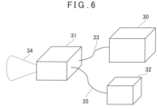
- a conventional grain-component analyzing instrument includes a light source module 30, a measurement optical system 31 and a spectroscope 32, and a halogen lamp is used as a light emission source.
- a light emitted by the light source module 30 (halogen lamp) is led to the measurement optical system 31 by an optical fiber 33 and is irradiated to an object to be measured (not shown) as a measuring light 34 from the measurement optical system 31.
- the measuring light 34 reflected by the object (reflected distance measuring light 34') is received in the measurement optical system 31 and is caused to enter the spectroscope 32 through an optical fiber 35.
- the reflected distance measuring light 34' is optically analyzed, a light absorption amount in specific wavelength bands are detected, and protein / moisture content rates of the grain are measured.
- the grain-component analyzing instrument Since the halogen lamp used in the grain-component analyzing instrument as described above has a high heat generation amount and a high power consumption, the grain-component analyzing instrument needs a high heat shut-off structure and a heat radiation structure such that heat generation does not influence a measurement and thus, the light source module 30 and the measurement optical system 31, the spectroscope 32 have separate and independent constitutions, and each unit is connected by the optical fibers 33, 35. Therefore, there has been a problem that a size reduction of a grain-component analyzing instrument is difficult.
- a halogen lamp is expensive and has a short life, and there is also a problem that the halogen lamp should be frequently replaced, which has caused rises of maintenance fees and running costs.
- a grain-component sensor comprises a white LED for emitting a white light as a light emission source, a sample holder in which a sample is filled, a spectroscope for receiving a reflected light from the sample and performing a spectroscopic analysis, and an optical filter provided on an optical path between the white LED and the sample holder, the optical filter has an optical characteristic that is a transmittance of substantially 100% in a wavelength band from 950 nm to 1100 nm and cuts a light in a visible light region to substantially 0%, a light emitted from the white LED transmits through the optical filter and is irradiated to the sample as a detection light in a wavelength band from 950 nm to 1100 nm, a diffused reflected light from the sample is condensed by a condenser lens and is entered the spectroscope.
- a light absorbing plate is provided on a reflection optical axis of the optical filter and absorbs a light reflected by the optical filter.
- the grain-component sensor according to a preferred embodiment further comprises a calibration module, the calibration module includes a standard white reflective board and a white-board insertion/removal module, and the white-board insertion/removal module is configured to be capable of inserting/removing the standard white reflective board into/from an optical path between the optical filter and the sample holder.
- the light emission source, the spectroscope, the optical filter and the calibration module are accommodated in a sensor case, and the sample holder can be detachably attached to the sensor case.
- the grain-component analyzing instrument comprises any one of the grain-component sensors described above, a control module, a storage module, a display module and a power supply module, the power supply module supplies powers to the grain-component sensor, the control module, the storage module and the display module, the control module is configured to perform a spectroscopic measurement of the grain-component sensor based on a program stored in the storage module, to acquire a reflection diffusion spectrum based on an acquired spectroscopy data, and to display the reflection diffusion spectrum, a spectroscopy data and a calculation result on the display module.
- the grain-component sensor comprises a white LED for emitting a white light as a light emission source, a sample holder in which a sample is filled, a spectroscope for receiving a reflected light from the sample and performing a spectroscopic analysis, and an optical filter provided on an optical path between the white LED and the sample holder, the optical filter has an optical characteristic that is a transmittance of substantially 100% in a wavelength band from 950 nm to 1100 nm and cuts a light in a visible light region to substantially 0%, a light emitted from the white LED transmits through the optical filter and is irradiated to the sample as a detection light in a wavelength band from 950 nm to 1100 nm, a diffused reflected light from the sample is condensed by a condenser lens and is entered the spectroscope.
- a white LED for emitting a white light as a light emission source
- a sample holder in which a sample is filled
- FIG. 1 shows a schematic configuration of a grain-component analyzing instrument 1 according to the present embodiment.
- a reference numeral 2 denotes a casing, and a component detection sensor 3, a control module 4, a storage module 5, a power supply module 6, a display module 7 and the like are provided inside the casing 2.
- the power supply module 6 supplies a power to the component detection sensor 3, the control module 4, the display module 7 and the like.
- various types of programs for the grain-component analyzing instrument 1 to perform spectroscopic measurements and a program for the grain-component analyzing instrument to calculate content rates of a water, a protein and the like based on a spectroscopy data acquired by spectroscopic measurements are stored. Further, in the storage module 5, a spectroscopy data acquired by spectroscopic measurements, and a calculation result of content rates and the like are stored.
- the control module 4 executes a program stored in the storage module 5 and executes required controls at required timings with respect to a spectroscope 11 (to be described later), a calibration module 14 (to be described later), a driver 18 (to be described later) and the like.
- the storage module 5 a semiconductor memory such as a RAM, a ROM, a FlashROM, a DRAM and the like, a magnetic recording memory such as a HDD and the like are used.
- a CPU specialized to the present embodiment or a general-purpose CPU, an embedded CPU, a microprocessor and the like are used.
- a sample holder 8 is provided in the component detection sensor 3.
- the sample holder 8 may be provided fixedly with respect to the component detection sensor 3 or may be provided detachably.
- sample 9 an object to be measured (sample) 9 is filled in the sample holder 8, and when the sample holder 8 is provided fixedly to the component detection sensor 3, it is possible to fill the sample 9 in the sample holder 8 from an outside of the grain-component analyzing instrument 1 and it is possible to discharge from the sample holder 8.
- sample holder 8 when the sample holder 8 is detachably attached to the component detection sensor 3, it is configured such that the sample holder 8 filled with the sample 9 is mounted on the component detection sensor 3 at a start of a measurement, and the sample holder 8 is removed from the component detection sensor 3 at a completion of a measurement.
- the sample holder 8 has an incident window 10 into which a detection light is incident, and the incident window 10 is sealed by a transparent plate such as a glass plate and the like.
- the sample holder 8 may be entirely constituted by a transparent material.
- the component detection sensor 3 mainly includes the spectroscope 11, a light source module 12, a photodetector 13, the calibration module 14.
- the spectroscope 11, the light source module 12, the photodetector 13 and the calibration module 14 may be accommodated in a sensor case 15, and the component detection sensor 3 may be unitized.
- the sample holder 8 may be detachably attached to the sensor case 15 or may be detachably attached to the casing 2.
- Electrical powers are supplied from the power supply module 6 to the spectroscope 11, the light source module 12, the photodetector 13 and the calibration module 14, respectively.
- the spectroscope 11 has an energy-dispersive Si detector for which an Si single crystal is used as a detection element and is configured such that the detection element spectro-analyzes a received light. Further, a range capable of analyzing by a Si detector is a near-infrared light with a wavelength of 1100 nm or less.
- the light source module 12 has a white LED 17 which emits a white light as a light emission source and a driver 18 which makes the white LED 17 emit light.
- An electrical power is supplied to the driver 18 from the power supply module 6, and a light emission is controlled by the control module 4. It is to be noted that a case in which a light emission source and the driver 18 are integrally constituted is shown, but the light emission source and the driver 18 may have a separate constitution.
- An optical filter 21 is disposed on an optical path (optical axis) of the white LED 17. As described later, the optical filter 21 has an optical characteristic which shuts off or dims a light in a visible light region and transmits a wavelength band required for a component detection.
- the white LED 17 it is possible to use a white LED in a market, a light emitting element and a lens are integrated, and a light beam from the light emission element is set to be a parallel light or to have a predetermined spread angle. Further, in the present embodiment, since it is possible to shorten a light projection distance to the sample 9, it is possible to directly irradiate the sample 9 with a light emitted from the white LED 17 without going through an optical system such as a lens. Therefore, in the present embodiment, it is possible to omit a light-projecting optical system.
- a water molecule and molecules constituting a protein, as contained in the sample 9 are detected by a spectroscopic analysis.
- a water shows a relatively strong absorption at 1940 nm, 1450 nm, 1190 nm, 970 nm, and 760 nm. Further, a protein shows a complicated spectrum in which absorptions by various functional groups are overlapped, but it is known to have a characteristic absorption band at 2180 nm, 2050 nm.
- a near-infrared spectroscopy is performed by using a wavelength range of a wavelength 1100 nm or less, and it is possible to use a Si detector.
- a white light is emitted from the white LED 17, and the white light contains substantially the entire region of wavelength bands. It is preferred to shut off the light other than wavelength band required for detecting component. Further, as a characteristic of a white LED, since output of longer wavelength region than infrared region (900 nm) is drastically smaller than output of visible region (1/10, for instance), a saturation of a spectral sensitivity in a visible light region should be avoided.
- FIG.2 is a graph showing an optical characteristic of the optical filter 21, and a vertical axis indicates a transmittance and a horizontal axis indicates a wavelength.
- a curve A is a
- the curve A and the curve B substantially match, and the optical filter 21 has a transmittance of substantially 100% in a wavelength band from 950 nm to 1100 mm as used in the present embodiment.
- the optical filter 21 has an optical characteristic which transmits substantially 100% of a wavelength range of a wavelength from 1100 nm to 950 nm and cuts off a light in a wavelength region (visible light region) at 950 nm or less to approximately 0%.
- an optical characteristic of the optical filter 21 is set to 2.5% transmittance with respect to a visible region and substantially 100% transmittance with respect to an infrared region.
- an optimal transmittance of the optical filter 21 is different depending on the white LED 17 to be used and is not limited to a transmittance described above.
- a light irradiated the sample 9 has a wavelength range of a wavelength from 1100 nm to 950 nm. Since the irradiated light is limited to a wavelength band required for a component detection, an S/N of a detection result is improved. Further, it is also possible to avoid a saturation of a spectral sensitivity in a visible light region.
- a light 20 emitted from the white LED 17 is transmitted through the optical filter 21 and is irradiated to the sample 9 through the incident window 10.
- the optical filter 21 and the incident window 10 are inclined by a predetermined angle with respect to an optical axis of the white LED 17. Thereby, a light reflected by the optical filter 21 and the incident window 10 do not enter the white LED 17, and a light emission state in the white LED 17 is prevented from becoming unstable. It is to be noted that, in an illustration, the optical filter 21 and the incident window 10 are inclined by 45° with respect to an optical axis, respectively, but the inclined angle is not limited to this angle.
- the optical filter 21 transmits a wavelength of 1100 nm or less, but at the same time, reflects a white light at a surface of the optical filter 21.
- a light absorbing plate 23 is provided on a reflection optical axis of the white light. The light absorbing plate 23 absorbs a reflected light from the optical filter 21. The light absorbing plate 23 prevents a light reflected by the optical filter 21 from irregularity reflecting inside the casing 2 and prevents a detection result by the spectroscope 11 from being influenced thereby.
- a diffused reflected light reflected by the sample 9 and transmitted through the incident window 10 is condensed by a condenser lens 24 and is incident to the spectroscope 11.
- the spectroscope 11 spectro-analyzes a reflected light being incident and outputs a spectroscopy data to the control module 4.
- the control module 4 acquires a reflected diffused spectrum based on a spectroscopy data, further calculates contents of a moisture and a protein and displays calculation results of a reflected diffused spectrum, a spectroscopy data, a protein content rate, a moisture content rate, and the like on the display module 7.
- the calibration module 14 is provided.
- the calibration module 14 has at least a standard white reflective board 25 and a white-board insertion/removal module 26.
- the white-board insertion/removal module 26 inserts/removes the standard white reflective board 25 into/from an optical path of the light emitted from the white LED 17.
- the standard white reflective board 25 is inserted into an optical path between the optical filter 21 and the sample holder 8, the light 20 is irradiated on the standard white reflective board 25, and a reflected light from the standard white reflective board 25 is detected by the spectroscope 11 as a reference light for a calibration. Further, a driving of the white-board insertion/removal module 26 and a driving timing are controlled by the control module 4.
- a light beam in a wavelength region from 950 nm to 1100 nm (particularly, from 1000 nm to 1100 nm) is required, and when the white LED 17 is caused to emit a light such that a light intensity with a wavelength of this band is suitable for a measurement, a light intensity with a wavelength in a visible region (a wavelength at 950 nm or less) becomes strong, and a photodetector of the spectroscope 11 is saturated.
- FIG.3 shows a reflected spectroscopy data of the standard white reflective board 25 acquired by inserting the standard white reflective board 25 into an optical path.
- a vertical axis indicates an intensity of a light receiving signal
- a horizontal axis indicates a wavelength.
- a curve A is a reflective spectroscopy data in a state without the optical filter 21, and a photodetector is saturated at a wavelength of 950 nm or less.
- a curve B shows a reflective spectroscopy data of the standard white reflective board 25 when the light 20 is emitted through the optical filter 21.
- the curve B shows that, by providing the optical filter 21, it is possible to acquire a reflective spectroscopy data without a saturation in all wavelength regions.
- FIG.4 shows a reflective spectroscopy data of a standard white reflective board as a curve A and a reflective spectroscopy data from the sample 9 (wheat in the present embodiment) as a curve B, in a state where the optical filter 21 is provided.
- a vertical axis indicates an intensity of a light receiving signal
- a horizontal axis indicates a wavelength.
- a curve A shows a reflective spectroscopy data in a calibration state.
- a curve B shows that it is possible to also acquire a light intensity required for a measurement with respect to a reflected light from a sample in all wavelength regions, and an effectiveness of the optical filter 21 is shown. Therefore, by a combination of the white LED 17 and the optical filter 21, it is possible to also perform a component analysis with respect to an object to be measured other than grain.
- FIG.5 shows measurement results of a grain-component analyzing instrument of a conventional type using a halogen lamp and of a grain-component analyzing instrument according to the present embodiment.
- a vertical axis indicates a relative reflectance
- a horizontal axis indicates a wavelength.
- a relative reflectance means that how much a light energy radiated from a colorimeter is reflected and returned from a test surface with respect to reflection from a reference surface is expressed by %.
- a curve A is an analysis data of a grain-component analyzing instrument of a conventional type
- a curve B shows an analysis data of a grain-component analyzing instrument in the present embodiment.
- a white LED 17 is used as a light source module in the present embodiment, and the white LED 17 as used is small with an outer shape of approximately 5 ⁇ 5 ⁇ 5.5 (mm), and further, a power consumption is 2.3 W. Further, a life is approximately 40000 Hr.
- a power consumption of a halogen lamp is 100 W, and further, a size of a power supply module by considering a heat radiation of a halogen lamp is approximately ⁇ 50 ⁇ 45 mm, and a life of a halogen lamp is approximately 1000 Hr.
- a light emission source itself is small, a power consumption is 2.3 W, a heat generation amount is drastically small, and a special heat radiation structure is not needed and thus, it is possible to markedly reduce a size of a light source module.
- a spectroscope 11, a control module 4, a storage module 5, the display module 7 do not have to be separated but can be integrated and thus, it is possible to reduce a size and a weight of a grain-component analyzing instrument 1.
Landscapes
- Physics & Mathematics (AREA)
- Life Sciences & Earth Sciences (AREA)
- Chemical & Material Sciences (AREA)
- Health & Medical Sciences (AREA)
- General Physics & Mathematics (AREA)
- Analytical Chemistry (AREA)
- Biochemistry (AREA)
- General Health & Medical Sciences (AREA)
- Spectroscopy & Molecular Physics (AREA)
- Immunology (AREA)
- Pathology (AREA)
- Engineering & Computer Science (AREA)
- Mathematical Physics (AREA)
- Theoretical Computer Science (AREA)
- Botany (AREA)
- Wood Science & Technology (AREA)
- Food Science & Technology (AREA)
- Medicinal Chemistry (AREA)
- Investigating Or Analysing Materials By Optical Means (AREA)
Abstract
Description
- The present disclosure relates to a grain-component sensor and a grain-component analyzing instrument which analyzes components contained in grain by a spectroscopic method.
- With grain as an object, an analyzing instrument which optically analyzes components contained in grain is known.
- In recent agricultural machine such as a combine harvester, for instance, there is such a machine which has a GNSS sensor mounted and is capable of obtaining a positional information of a heavy machine during working.
- A grain-component analyzing instrument is mounted on an agricultural machine, and by acquiring a quality data such as protein/moisture content rates in grain during harvesting in real time and by associating an acquired data with a positional information of a field, it is possible to conduct an adjustment of an application rate of a fertilizer or an improvement of a soil and to be utilized for efficient farming programs for producing crops with high and constant qualities.
- Therefore, it is useful to mount the grain-component analyzing instrument on the agricultural machine for a development of an agriculture.
- Conventionally, as a grain-component analyzing instrument, there is a grain-component analyzing instrument which irradiates grain with a near-infrared light, detects light absorption amounts in wavelength bands specific to water molecule, and to molecule constituting protein, and measures a moisture content rate and a protein content rate.
- As shown in
FIG.6 , a conventional grain-component analyzing instrument includes alight source module 30, a measurementoptical system 31 and aspectroscope 32, and a halogen lamp is used as a light emission source. - A light emitted by the light source module 30 (halogen lamp) is led to the measurement
optical system 31 by anoptical fiber 33 and is irradiated to an object to be measured (not shown) as ameasuring light 34 from the measurementoptical system 31. Themeasuring light 34 reflected by the object (reflected distance measuring light 34') is received in the measurementoptical system 31 and is caused to enter thespectroscope 32 through anoptical fiber 35. In thespectroscope 32, the reflected distance measuring light 34' is optically analyzed, a light absorption amount in specific wavelength bands are detected, and protein / moisture content rates of the grain are measured. - Since the halogen lamp used in the grain-component analyzing instrument as described above has a high heat generation amount and a high power consumption, the grain-component analyzing instrument needs a high heat shut-off structure and a heat radiation structure such that heat generation does not influence a measurement and thus, the
light source module 30 and the measurementoptical system 31, thespectroscope 32 have separate and independent constitutions, and each unit is connected by theoptical fibers - Further, a halogen lamp is expensive and has a short life, and there is also a problem that the halogen lamp should be frequently replaced, which has caused rises of maintenance fees and running costs.
- It is an object of the present invention to provide a grain-component sensor and a grain-component analyzing instrument which has a small size and is capable of reducing maintenance fees and running costs.
- To attain the object as described above, a grain-component sensor according to the present embodiment comprises a white LED for emitting a white light as a light emission source, a sample holder in which a sample is filled, a spectroscope for receiving a reflected light from the sample and performing a spectroscopic analysis, and an optical filter provided on an optical path between the white LED and the sample holder, the optical filter has an optical characteristic that is a transmittance of substantially 100% in a wavelength band from 950 nm to 1100 nm and cuts a light in a visible light region to substantially 0%, a light emitted from the white LED transmits through the optical filter and is irradiated to the sample as a detection light in a wavelength band from 950 nm to 1100 nm, a diffused reflected light from the sample is condensed by a condenser lens and is entered the spectroscope.
- Further, in the grain-component sensor according to a preferred embodiment, a light absorbing plate is provided on a reflection optical axis of the optical filter and absorbs a light reflected by the optical filter.
- Further, the grain-component sensor according to a preferred embodiment further comprises a calibration module, the calibration module includes a standard white reflective board and a white-board insertion/removal module, and the white-board insertion/removal module is configured to be capable of inserting/removing the standard white reflective board into/from an optical path between the optical filter and the sample holder.
- Further, in the grain-component sensor according to a preferred embodiment, the light emission source, the spectroscope, the optical filter and the calibration module are accommodated in a sensor case, and the sample holder can be detachably attached to the sensor case.
- Furthermore, the grain-component analyzing instrument according to the present invention comprises any one of the grain-component sensors described above, a control module, a storage module, a display module and a power supply module, the power supply module supplies powers to the grain-component sensor, the control module, the storage module and the display module, the control module is configured to perform a spectroscopic measurement of the grain-component sensor based on a program stored in the storage module, to acquire a reflection diffusion spectrum based on an acquired spectroscopy data, and to display the reflection diffusion spectrum, a spectroscopy data and a calculation result on the display module.
- According to the present embodiment, the grain-component sensor comprises a white LED for emitting a white light as a light emission source, a sample holder in which a sample is filled, a spectroscope for receiving a reflected light from the sample and performing a spectroscopic analysis, and an optical filter provided on an optical path between the white LED and the sample holder, the optical filter has an optical characteristic that is a transmittance of substantially 100% in a wavelength band from 950 nm to 1100 nm and cuts a light in a visible light region to substantially 0%, a light emitted from the white LED transmits through the optical filter and is irradiated to the sample as a detection light in a wavelength band from 950 nm to 1100 nm, a diffused reflected light from the sample is condensed by a condenser lens and is entered the spectroscope. As a result, it is possible to promote a size reduction of a light emission source and further, a size reduction, a power-saving, a longer life of a grain-component analyzing instrument, and maintenance fees and running costs are reduced.
-
-
FIG.1 is a schematic configuration drawing of a grain-component analyzing instrument according to an embodiment of the present invention. -
FIG.2 is a graph illustrating an optical characteristic (wavelength transmission characteristic) of an optical filter of the present embodiment. -
FIG.3 is a graph showing a dimming action of the optical filter. -
FIG.4 is a diagram illustrating a reflective spectroscopy data at a calibration and a reflective spectroscopy data at an actual measurement. -
FIG.5 is a graph showing an analysis data of the present embodiment and an analysis data of a conventional type. -
FIG.6 is a schematic diagram of a conventional grain-component analyzing instrument. - A description will be given below on an embodiment of the present invention by referring to the attached drawings.
-
FIG. 1 shows a schematic configuration of a grain-component analyzinginstrument 1 according to the present embodiment. - In
FIG.1 , areference numeral 2 denotes a casing, and acomponent detection sensor 3, a control module 4, astorage module 5, apower supply module 6, adisplay module 7 and the like are provided inside thecasing 2. Thepower supply module 6 supplies a power to thecomponent detection sensor 3, the control module 4, thedisplay module 7 and the like. - In the
storage module 5, various types of programs for the grain-component analyzinginstrument 1 to perform spectroscopic measurements and a program for the grain-component analyzing instrument to calculate content rates of a water, a protein and the like based on a spectroscopy data acquired by spectroscopic measurements are stored. Further, in thestorage module 5, a spectroscopy data acquired by spectroscopic measurements, and a calculation result of content rates and the like are stored. - The control module 4 executes a program stored in the
storage module 5 and executes required controls at required timings with respect to a spectroscope 11 (to be described later), a calibration module 14 (to be described later), a driver 18 (to be described later) and the like. - It is to be noted that, as the
storage module 5, a semiconductor memory such as a RAM, a ROM, a FlashROM, a DRAM and the like, a magnetic recording memory such as a HDD and the like are used. Further, as the control module 4, a CPU specialized to the present embodiment or a general-purpose CPU, an embedded CPU, a microprocessor and the like are used. - A
sample holder 8 is provided in thecomponent detection sensor 3. Thesample holder 8 may be provided fixedly with respect to thecomponent detection sensor 3 or may be provided detachably. - It is configured such that an object to be measured (sample) 9 is filled in the
sample holder 8, and when thesample holder 8 is provided fixedly to thecomponent detection sensor 3, it is possible to fill the sample 9 in thesample holder 8 from an outside of the grain-component analyzinginstrument 1 and it is possible to discharge from thesample holder 8. - Further, when the
sample holder 8 is detachably attached to thecomponent detection sensor 3, it is configured such that thesample holder 8 filled with the sample 9 is mounted on thecomponent detection sensor 3 at a start of a measurement, and thesample holder 8 is removed from thecomponent detection sensor 3 at a completion of a measurement. - Further, when a plurality of the
sample holders 8 filled with the sample 9 are prepared in advance and thesample holder 8 is replaced at each completion of a measurement, a measurement can be performed efficiently. - The
sample holder 8 has anincident window 10 into which a detection light is incident, and theincident window 10 is sealed by a transparent plate such as a glass plate and the like. Alternatively, thesample holder 8 may be entirely constituted by a transparent material. - Subsequently, a description will be given on the
component detection sensor 3. - The
component detection sensor 3 mainly includes the spectroscope 11, alight source module 12, aphotodetector 13, thecalibration module 14. The spectroscope 11, thelight source module 12, thephotodetector 13 and thecalibration module 14 may be accommodated in asensor case 15, and thecomponent detection sensor 3 may be unitized. In this case, thesample holder 8 may be detachably attached to thesensor case 15 or may be detachably attached to thecasing 2. - Electrical powers are supplied from the
power supply module 6 to the spectroscope 11, thelight source module 12, thephotodetector 13 and thecalibration module 14, respectively. - The spectroscope 11 has an energy-dispersive Si detector for which an Si single crystal is used as a detection element and is configured such that the detection element spectro-analyzes a received light. Further, a range capable of analyzing by a Si detector is a near-infrared light with a wavelength of 1100 nm or less.
- The
light source module 12 has awhite LED 17 which emits a white light as a light emission source and adriver 18 which makes thewhite LED 17 emit light. An electrical power is supplied to thedriver 18 from thepower supply module 6, and a light emission is controlled by the control module 4. It is to be noted that a case in which a light emission source and thedriver 18 are integrally constituted is shown, but the light emission source and thedriver 18 may have a separate constitution. - An
optical filter 21 is disposed on an optical path (optical axis) of thewhite LED 17. As described later, theoptical filter 21 has an optical characteristic which shuts off or dims a light in a visible light region and transmits a wavelength band required for a component detection. - For the
white LED 17, it is possible to use a white LED in a market, a light emitting element and a lens are integrated, and a light beam from the light emission element is set to be a parallel light or to have a predetermined spread angle. Further, in the present embodiment, since it is possible to shorten a light projection distance to the sample 9, it is possible to directly irradiate the sample 9 with a light emitted from thewhite LED 17 without going through an optical system such as a lens. Therefore, in the present embodiment, it is possible to omit a light-projecting optical system. - Subsequently, in the present embodiment, a water molecule and molecules constituting a protein, as contained in the sample 9, are detected by a spectroscopic analysis.
- A water shows a relatively strong absorption at 1940 nm, 1450 nm, 1190 nm, 970 nm, and 760 nm. Further, a protein shows a complicated spectrum in which absorptions by various functional groups are overlapped, but it is known to have a characteristic absorption band at 2180 nm, 2050 nm.
- Therefore, it is preferable to use a long wavelength of 1000 nm or more for a near-infrared spectroscopy, but an expensive InGaAs detector should be used for this wavelength band. Thus, in the present embodiment, a near-infrared spectroscopy is performed by using a wavelength range of a
wavelength 1100 nm or less, and it is possible to use a Si detector. - A white light is emitted from the
white LED 17, and the white light contains substantially the entire region of wavelength bands. It is preferred to shut off the light other than wavelength band required for detecting component. Further, as a characteristic of a white LED, since output of longer wavelength region than infrared region (900 nm) is drastically smaller than output of visible region (1/10, for instance), a saturation of a spectral sensitivity in a visible light region should be avoided. -
FIG.2 is a graph showing an optical characteristic of theoptical filter 21, and a vertical axis indicates a transmittance and a horizontal axis indicates a wavelength. - Further, in
FIG.2 , a curve A is a - wavelength/transmittance curve required in the present embodiment, and a curve B is an actual
- wavelength/transmittance curve of the
optical filter 21 used in the present embodiment. - The curve A and the curve B substantially match, and the
optical filter 21 has a transmittance of substantially 100% in a wavelength band from 950 nm to 1100 mm as used in the present embodiment. - That is, the
optical filter 21 has an optical characteristic which transmits substantially 100% of a wavelength range of a wavelength from 1100 nm to 950 nm and cuts off a light in a wavelength region (visible light region) at 950 nm or less to approximately 0%. - In the present embodiment, an optical characteristic of the
optical filter 21 is set to 2.5% transmittance with respect to a visible region and substantially 100% transmittance with respect to an infrared region. By allowing a transmission of 2.5% also with respect to a light in a visible region, as described later, it becomes possible to spectro-analyze molecules other than water molecules, protein molecules. - It is to be noted that, it is considered that an optimal transmittance of the
optical filter 21 is different depending on thewhite LED 17 to be used and is not limited to a transmittance described above. - Therefore, a light irradiated the sample 9 has a wavelength range of a wavelength from 1100 nm to 950 nm. Since the irradiated light is limited to a wavelength band required for a component detection, an S/N of a detection result is improved. Further, it is also possible to avoid a saturation of a spectral sensitivity in a visible light region.
- A light 20 emitted from the
white LED 17 is transmitted through theoptical filter 21 and is irradiated to the sample 9 through theincident window 10. - The
optical filter 21 and theincident window 10 are inclined by a predetermined angle with respect to an optical axis of thewhite LED 17. Thereby, a light reflected by theoptical filter 21 and theincident window 10 do not enter thewhite LED 17, and a light emission state in thewhite LED 17 is prevented from becoming unstable. It is to be noted that, in an illustration, theoptical filter 21 and theincident window 10 are inclined by 45° with respect to an optical axis, respectively, but the inclined angle is not limited to this angle. - The
optical filter 21 transmits a wavelength of 1100 nm or less, but at the same time, reflects a white light at a surface of theoptical filter 21. In the present embodiment, alight absorbing plate 23 is provided on a reflection optical axis of the white light. Thelight absorbing plate 23 absorbs a reflected light from theoptical filter 21. Thelight absorbing plate 23 prevents a light reflected by theoptical filter 21 from irregularity reflecting inside thecasing 2 and prevents a detection result by the spectroscope 11 from being influenced thereby. - A diffused reflected light reflected by the sample 9 and transmitted through the
incident window 10 is condensed by acondenser lens 24 and is incident to the spectroscope 11. - The spectroscope 11 spectro-analyzes a reflected light being incident and outputs a spectroscopy data to the control module 4.
- The control module 4 acquires a reflected diffused spectrum based on a spectroscopy data, further calculates contents of a moisture and a protein and displays calculation results of a reflected diffused spectrum, a spectroscopy data, a protein content rate, a moisture content rate, and the like on the
display module 7. - Next, in the present embodiment, in order to guarantee a measurement accuracy, the
calibration module 14 is provided. - The
calibration module 14 has at least a standard whitereflective board 25 and a white-board insertion/removal module 26. - The white-board insertion/
removal module 26 inserts/removes the standard whitereflective board 25 into/from an optical path of the light emitted from thewhite LED 17. Before and after a component analysis of the sample 9 or either one of before and after, or every predetermined time, the standard whitereflective board 25 is inserted into an optical path between theoptical filter 21 and thesample holder 8, the light 20 is irradiated on the standard whitereflective board 25, and a reflected light from the standard whitereflective board 25 is detected by the spectroscope 11 as a reference light for a calibration. Further, a driving of the white-board insertion/removal module 26 and a driving timing are controlled by the control module 4. - Next, a description will be given on a relationship between the
optical filter 21 and the standard whitereflective board 25. - As described above, in the present embodiment, a light beam in a wavelength region from 950 nm to 1100 nm (particularly, from 1000 nm to 1100 nm) is required, and when the
white LED 17 is caused to emit a light such that a light intensity with a wavelength of this band is suitable for a measurement, a light intensity with a wavelength in a visible region (a wavelength at 950 nm or less) becomes strong, and a photodetector of the spectroscope 11 is saturated. -
FIG.3 shows a reflected spectroscopy data of the standard whitereflective board 25 acquired by inserting the standard whitereflective board 25 into an optical path. InFIG.3 , a vertical axis indicates an intensity of a light receiving signal, and a horizontal axis indicates a wavelength. Further, in the drawing, a curve A is a reflective spectroscopy data in a state without theoptical filter 21, and a photodetector is saturated at a wavelength of 950 nm or less. - Next, a curve B shows a reflective spectroscopy data of the standard white
reflective board 25 when the light 20 is emitted through theoptical filter 21. The curve B shows that, by providing theoptical filter 21, it is possible to acquire a reflective spectroscopy data without a saturation in all wavelength regions. -
FIG.4 shows a reflective spectroscopy data of a standard white reflective board as a curve A and a reflective spectroscopy data from the sample 9 (wheat in the present embodiment) as a curve B, in a state where theoptical filter 21 is provided. InFIG.4 , a vertical axis indicates an intensity of a light receiving signal, and a horizontal axis indicates a wavelength. - A curve A shows a reflective spectroscopy data in a calibration state.
- A curve B shows that it is possible to also acquire a light intensity required for a measurement with respect to a reflected light from a sample in all wavelength regions, and an effectiveness of the
optical filter 21 is shown. Therefore, by a combination of thewhite LED 17 and theoptical filter 21, it is possible to also perform a component analysis with respect to an object to be measured other than grain. - By performing a calibration, it is possible to detect a light emission state of the
light source module 12 and abnormality of a measurement state, and the like. -
FIG.5 shows measurement results of a grain-component analyzing instrument of a conventional type using a halogen lamp and of a grain-component analyzing instrument according to the present embodiment. InFIG.5 , a vertical axis indicates a relative reflectance, and a horizontal axis indicates a wavelength. Here, a relative reflectance means that how much a light energy radiated from a colorimeter is reflected and returned from a test surface with respect to reflection from a reference surface is expressed by %. - With wheat as an object to be measured, a curve A is an analysis data of a grain-component analyzing instrument of a conventional type, and a curve B shows an analysis data of a grain-component analyzing instrument in the present embodiment.
- Since measurement timings and samples are different, a simple comparison is difficult, but shapes of curves substantially match, and it is known that a measurement by a grain-component analyzing instrument in the present embodiment is useful.
- As described above, a
white LED 17 is used as a light source module in the present embodiment, and thewhite LED 17 as used is small with an outer shape of approximately 5 × 5 × 5.5 (mm), and further, a power consumption is 2.3 W. Further, a life is approximately 40000 Hr. - It is to be noted that a power consumption of a halogen lamp is 100 W, and further, a size of a power supply module by considering a heat radiation of a halogen lamp is approximately ϕ50 × 45 mm, and a life of a halogen lamp is approximately 1000 Hr.
- Therefore, in the present embodiment, a light emission source itself is small, a power consumption is 2.3 W, a heat generation amount is drastically small, and a special heat radiation structure is not needed and thus, it is possible to markedly reduce a size of a light source module. Further, a spectroscope 11, a control module 4, a
storage module 5, thedisplay module 7 do not have to be separated but can be integrated and thus, it is possible to reduce a size and a weight of a grain-component analyzing instrument 1. - Further, since a life of the
white LED 17 is markedly longer than a halogen lamp, it is possible to reduce maintenance fees and running costs. - In the present embodiment, it is possible to reduce sizes and weights of a grain-component sensor and a grain-component analyzing instrument and to realize an integration of a grain-component sensor and a grain-component analyzing instrument, and a power consumption is small and thus, it is easy to be mounted on a movable machine such as an agricultural machine.
Claims (5)
- A grain-component sensor comprising: a white LED (17) for emitting a white light as a light emission source, a sample holder (8) in which a sample (9) is filled, a spectroscope (11) for receiving a reflected light from said sample and performing a spectroscopic analysis, and an optical filter (21) provided on an optical path between said white LED and said sample holder, wherein said optical filter has an optical characteristic that is a transmittance of substantially 100% in a wavelength band from 950 nm to 1100 nm and cuts a light in a visible light region to substantially 0%, a light emitted from said white LED transmits through said optical filter and is irradiated to said sample as a detection light in a wavelength band from 950 nm to 1100 nm, a diffused reflected light from said sample is condensed by a condenser lens (24) and is entered said spectroscope.
- The grain-component sensor according to claim 1, wherein a light absorbing plate (23) is provided on a reflection optical axis of said optical filter (21) and absorbs a light reflected by said optical filter.
- The grain-component sensor according to claim 1 or 2, further comprising a calibration module (14), wherein said calibration module includes a standard white reflective board (25) and a white-board insertion/removal module (26), and said white-board insertion/removal module is configured to be capable of inserting/removing said standard white reflective board into/from an optical path between said optical filter (21) and said sample holder (8).
- The grain-component sensor according to claim 3, wherein said light emission source, said spectroscope (11), said optical filter (21) and said calibration module (14) are accommodated in a sensor case (15), and said sample holder (8) can be detachably attached to said sensor case.
- The grain-component analyzing instrument, comprising the grain-component sensor according to any one of claims 1 to 4, a control module (4), a storage module (5), a display module (7) and a power supply module (6), wherein said power supply module supplies powers to said grain-component sensor, said control module, said storage module and said display module, wherein said control module is configured to perform a spectroscopic measurement of said grain-component sensor based on a program stored in said storage module, to acquire a reflection diffusion spectrum based on an acquired spectroscopy data, and to display the reflection diffusion spectrum, a spectroscopy data and a calculation result on said display module.
Applications Claiming Priority (1)
| Application Number | Priority Date | Filing Date | Title |
|---|---|---|---|
| JP2022044313A JP2023137889A (en) | 2022-03-18 | 2022-03-18 | Grain component sensor and grain component analyzer |
Publications (1)
| Publication Number | Publication Date |
|---|---|
| EP4246127A1 true EP4246127A1 (en) | 2023-09-20 |
Family
ID=85640687
Family Applications (1)
| Application Number | Title | Priority Date | Filing Date |
|---|---|---|---|
| EP23161779.6A Withdrawn EP4246127A1 (en) | 2022-03-18 | 2023-03-14 | Grain-component sensor and grain-component analyzing instrument |
Country Status (4)
| Country | Link |
|---|---|
| US (1) | US20230296500A1 (en) |
| EP (1) | EP4246127A1 (en) |
| JP (1) | JP2023137889A (en) |
| CN (1) | CN116773466A (en) |
Families Citing this family (1)
| Publication number | Priority date | Publication date | Assignee | Title |
|---|---|---|---|---|
| CN117589680B (en) * | 2023-11-27 | 2024-12-24 | 东莞市搏信智能控制技术有限公司 | Optical detection device and detection circuit |
Citations (6)
| Publication number | Priority date | Publication date | Assignee | Title |
|---|---|---|---|---|
| EP0260942A2 (en) * | 1986-09-19 | 1988-03-23 | Satake Engineering Co., Ltd. | Measuring apparatus for amylose and/or amylopectin content in rice |
| WO2002048687A2 (en) * | 2000-10-30 | 2002-06-20 | Monsanto Technology Llc | Methods and devices for analyzing agricultural products |
| US6483583B1 (en) * | 1997-02-27 | 2002-11-19 | Textron Systems Corporation | Near infrared spectrometry for real time analysis of substances |
| US20160091367A1 (en) * | 2014-09-29 | 2016-03-31 | Innovative Science Tools, Inc. | Solid State Broad Band Near-Infrared Light Source |
| JP2016170968A (en) * | 2015-03-12 | 2016-09-23 | パナソニックIpマネジメント株式会社 | Luminaire |
| CN106841105B (en) * | 2017-04-14 | 2019-08-06 | 北京国科虹谱光电技术有限公司 | A multi-wavelength near-infrared spectroscopy measurement device for substance identification |
Family Cites Families (17)
| Publication number | Priority date | Publication date | Assignee | Title |
|---|---|---|---|---|
| DE2924125C2 (en) * | 1979-06-15 | 1982-10-28 | Bodenseewerk Perkin-Elmer & Co GmbH, 7770 Überlingen | Device for suppressing stray light in grating monochromators |
| JP2614117B2 (en) * | 1989-10-06 | 1997-05-28 | ソニー・テクトロニクス 株式会社 | Optical attenuator |
| US6421990B1 (en) * | 1999-05-19 | 2002-07-23 | Deere & Company | Measuring device for measuring components in and/or properties of crop material |
| US6749810B2 (en) * | 2000-06-20 | 2004-06-15 | Gary W. Clem, Inc. | Method and apparatus for presenting grain for NIR spectography examination |
| AU2003214235B2 (en) * | 2002-03-20 | 2008-07-03 | Ag Leader Technolgy, Inc. | High speed analyzer using near infrared radiation transmitted through thick samples of optically dense material |
| JP2003161697A (en) * | 2002-10-07 | 2003-06-06 | Iseki & Co Ltd | Agricultural product spectrometer |
| US7859674B2 (en) * | 2006-11-20 | 2010-12-28 | Pioneer Hi-Bred International, Inc. | System and method for measuring a harvest quality parameter on a harvesting device |
| JP2011253077A (en) * | 2010-06-03 | 2011-12-15 | Sony Corp | Light source device and projection device |
| JP2012147279A (en) * | 2011-01-13 | 2012-08-02 | Spectr Design Kk | Near-infrared imaging apparatus |
| WO2015195479A1 (en) * | 2014-06-16 | 2015-12-23 | Murphy Brown, Llc | Method and system for in-line analysis of products |
| EP3469407A4 (en) * | 2016-06-09 | 2020-02-26 | 3M Innovative Properties Company | OPTICAL FILTER |
| JP6924561B2 (en) * | 2016-07-04 | 2021-08-25 | 株式会社相馬光学 | Reference white plate unit for near-infrared interaction spectroscopy measurement and reference spectral intensity acquisition method for near-infrared interaction spectroscopy |
| AR107595A1 (en) * | 2017-02-10 | 2018-05-16 | Tecnocientifica S A | SPECTROMETRIC PROBE FOR SAMPLING BULK MATERIAL AND AUTOMATIC SAMPLING HEATER INCORPORATING THE PROBE |
| JP2019204831A (en) * | 2018-05-22 | 2019-11-28 | ウシオオプトセミコンダクター株式会社 | Light emitting element |
| GB2594980B (en) * | 2020-05-14 | 2025-01-01 | Agilent Tech Lda Uk Limited | Spectral analysis of a sample |
| US20240249491A1 (en) * | 2021-05-26 | 2024-07-25 | Basf Coatings Gmbh | System and method for object recognition utilizing reflective light blocking |
| CN118613828A (en) * | 2022-01-19 | 2024-09-06 | 碳自主机器人系统公司 | Systems and methods for object tracking and position prediction |
-
2022
- 2022-03-18 JP JP2022044313A patent/JP2023137889A/en active Pending
-
2023
- 2023-03-13 US US18/120,743 patent/US20230296500A1/en not_active Abandoned
- 2023-03-14 EP EP23161779.6A patent/EP4246127A1/en not_active Withdrawn
- 2023-03-17 CN CN202310269072.5A patent/CN116773466A/en active Pending
Patent Citations (6)
| Publication number | Priority date | Publication date | Assignee | Title |
|---|---|---|---|---|
| EP0260942A2 (en) * | 1986-09-19 | 1988-03-23 | Satake Engineering Co., Ltd. | Measuring apparatus for amylose and/or amylopectin content in rice |
| US6483583B1 (en) * | 1997-02-27 | 2002-11-19 | Textron Systems Corporation | Near infrared spectrometry for real time analysis of substances |
| WO2002048687A2 (en) * | 2000-10-30 | 2002-06-20 | Monsanto Technology Llc | Methods and devices for analyzing agricultural products |
| US20160091367A1 (en) * | 2014-09-29 | 2016-03-31 | Innovative Science Tools, Inc. | Solid State Broad Band Near-Infrared Light Source |
| JP2016170968A (en) * | 2015-03-12 | 2016-09-23 | パナソニックIpマネジメント株式会社 | Luminaire |
| CN106841105B (en) * | 2017-04-14 | 2019-08-06 | 北京国科虹谱光电技术有限公司 | A multi-wavelength near-infrared spectroscopy measurement device for substance identification |
Also Published As
| Publication number | Publication date |
|---|---|
| CN116773466A (en) | 2023-09-19 |
| US20230296500A1 (en) | 2023-09-21 |
| JP2023137889A (en) | 2023-09-29 |
Similar Documents
| Publication | Publication Date | Title |
|---|---|---|
| RU2004123207A (en) | METHOD FOR ANALYSIS OF HEMOGLOBIN AND SYSTEM FOR ITS IMPLEMENTATION | |
| EP3411689B1 (en) | System and method for optical absorbance measurement of whole blood | |
| TWI613434B (en) | Spectrometry device and spectrometry method | |
| JP7056612B2 (en) | Turbidity measurement method and turbidity meter | |
| JPH05203566A (en) | Quantitative decision method and appara- tus for concentration of optically active substance | |
| EP0121404B1 (en) | A photometric light absorption measuring apparatus | |
| JP2006125940A (en) | Photoluminescence quantum yield measurement method and apparatus used therefor | |
| US20230296500A1 (en) | Grain-component sensor and grain-component analyzing instrument | |
| JP5011389B2 (en) | System and method for compensating system delay in sample analysis | |
| KR20100082476A (en) | Development of portable type based noninvasive saccharometer | |
| KR102498594B1 (en) | Method for measuring multi-spectral properties of tissue and system therefor | |
| US20150137008A1 (en) | Device and method for determining the concentration of fluorophores in a sample | |
| US20230296506A1 (en) | Granular-substance component measuring method and granular-substance component measuring instrument | |
| CN101784884B (en) | Method and system for characterizing pigmented biological tissue | |
| US4970671A (en) | Bias drift compensation in near infrared quantitative analysis instruments | |
| JP2898489B2 (en) | Equipment for spectrophotometric analysis | |
| JP2008157809A (en) | Laser output control device and optical measuring unit | |
| US20120252131A1 (en) | Biological material analyzer and biological material analysis method | |
| JP6924561B2 (en) | Reference white plate unit for near-infrared interaction spectroscopy measurement and reference spectral intensity acquisition method for near-infrared interaction spectroscopy | |
| KR200404482Y1 (en) | Portable Data Aquisition Apparatus for Internal Qualtity of Fruits | |
| KR100414186B1 (en) | the automatic calibration system and for measuring internal qualities of fruits on both side | |
| JP7760853B2 (en) | Fluorescence measurement equipment | |
| KR101205779B1 (en) | Apparatus for measuring moisture of object to be measured | |
| JP2004184113A (en) | Egg candler | |
| RU2001131870A (en) | A method for determining the concentration of alcohol in solutions and a device for its implementation (options) |
Legal Events
| Date | Code | Title | Description |
|---|---|---|---|
| PUAI | Public reference made under article 153(3) epc to a published international application that has entered the european phase |
Free format text: ORIGINAL CODE: 0009012 |
|
| STAA | Information on the status of an ep patent application or granted ep patent |
Free format text: STATUS: REQUEST FOR EXAMINATION WAS MADE |
|
| 17P | Request for examination filed |
Effective date: 20230314 |
|
| AK | Designated contracting states |
Kind code of ref document: A1 Designated state(s): AL AT BE BG CH CY CZ DE DK EE ES FI FR GB GR HR HU IE IS IT LI LT LU LV MC ME MK MT NL NO PL PT RO RS SE SI SK SM TR |
|
| RBV | Designated contracting states (corrected) |
Designated state(s): AL AT BE BG CH CY CZ DE DK EE ES FI FR GB GR HR HU IE IS IT LI LT LU LV MC ME MK MT NL NO PL PT RO RS SE SI SK SM TR |
|
| REG | Reference to a national code |
Ref country code: DE Ref legal event code: R079 Free format text: PREVIOUS MAIN CLASS: G01N0021359000 Ipc: G01N0021250000 |
|
| GRAP | Despatch of communication of intention to grant a patent |
Free format text: ORIGINAL CODE: EPIDOSNIGR1 |
|
| STAA | Information on the status of an ep patent application or granted ep patent |
Free format text: STATUS: GRANT OF PATENT IS INTENDED |
|
| RIC1 | Information provided on ipc code assigned before grant |
Ipc: G01N 33/02 20060101ALN20250214BHEP Ipc: G01N 21/84 20060101ALN20250214BHEP Ipc: G01N 21/03 20060101ALN20250214BHEP Ipc: G01N 21/47 20060101ALI20250214BHEP Ipc: G01N 21/359 20140101ALI20250214BHEP Ipc: G01N 21/3563 20140101ALI20250214BHEP Ipc: G01N 21/27 20060101ALI20250214BHEP Ipc: G01N 21/25 20060101AFI20250214BHEP |
|
| INTG | Intention to grant announced |
Effective date: 20250228 |
|
| GRAJ | Information related to disapproval of communication of intention to grant by the applicant or resumption of examination proceedings by the epo deleted |
Free format text: ORIGINAL CODE: EPIDOSDIGR1 |
|
| STAA | Information on the status of an ep patent application or granted ep patent |
Free format text: STATUS: REQUEST FOR EXAMINATION WAS MADE |
|
| GRAS | Grant fee paid |
Free format text: ORIGINAL CODE: EPIDOSNIGR3 |
|
| STAA | Information on the status of an ep patent application or granted ep patent |
Free format text: STATUS: GRANT OF PATENT IS INTENDED |
|
| GRAP | Despatch of communication of intention to grant a patent |
Free format text: ORIGINAL CODE: EPIDOSNIGR1 |
|
| STAA | Information on the status of an ep patent application or granted ep patent |
Free format text: STATUS: THE APPLICATION HAS BEEN WITHDRAWN |
|
| INTC | Intention to grant announced (deleted) | ||
| RIC1 | Information provided on ipc code assigned before grant |
Ipc: G01N 33/02 20060101ALN20250605BHEP Ipc: G01N 21/84 20060101ALN20250605BHEP Ipc: G01N 21/03 20060101ALN20250605BHEP Ipc: G01N 21/47 20060101ALI20250605BHEP Ipc: G01N 21/359 20140101ALI20250605BHEP Ipc: G01N 21/3563 20140101ALI20250605BHEP Ipc: G01N 21/27 20060101ALI20250605BHEP Ipc: G01N 21/25 20060101AFI20250605BHEP |
|
| INTG | Intention to grant announced |
Effective date: 20250624 |
|
| 18W | Application withdrawn |
Effective date: 20250630 |