EP4246112A1 - Tire load predicting system, tire load predicting program, and tire load predicting method - Google Patents
Tire load predicting system, tire load predicting program, and tire load predicting method Download PDFInfo
- Publication number
- EP4246112A1 EP4246112A1 EP21891720.1A EP21891720A EP4246112A1 EP 4246112 A1 EP4246112 A1 EP 4246112A1 EP 21891720 A EP21891720 A EP 21891720A EP 4246112 A1 EP4246112 A1 EP 4246112A1
- Authority
- EP
- European Patent Office
- Prior art keywords
- tire
- velocity
- load prediction
- basis
- deflection
- Prior art date
- Legal status (The legal status is an assumption and is not a legal conclusion. Google has not performed a legal analysis and makes no representation as to the accuracy of the status listed.)
- Granted
Links
Images




Classifications
-
- B—PERFORMING OPERATIONS; TRANSPORTING
- B60—VEHICLES IN GENERAL
- B60C—VEHICLE TYRES; TYRE INFLATION; TYRE CHANGING; CONNECTING VALVES TO INFLATABLE ELASTIC BODIES IN GENERAL; DEVICES OR ARRANGEMENTS RELATED TO TYRES
- B60C23/00—Devices for measuring, signalling, controlling, or distributing tyre pressure or temperature, specially adapted for mounting on vehicles; Arrangement of tyre inflating devices on vehicles, e.g. of pumps or of tanks; Tyre cooling arrangements
- B60C23/02—Signalling devices actuated by tyre pressure
- B60C23/04—Signalling devices actuated by tyre pressure mounted on the wheel or tyre
- B60C23/0486—Signalling devices actuated by tyre pressure mounted on the wheel or tyre comprising additional sensors in the wheel or tyre mounted monitoring device, e.g. movement sensors, microphones or earth magnetic field sensors
- B60C23/0488—Movement sensor, e.g. for sensing angular speed, acceleration or centripetal force
-
- G—PHYSICS
- G01—MEASURING; TESTING
- G01M—TESTING STATIC OR DYNAMIC BALANCE OF MACHINES OR STRUCTURES; TESTING OF STRUCTURES OR APPARATUS, NOT OTHERWISE PROVIDED FOR
- G01M17/00—Testing of vehicles
- G01M17/007—Wheeled or endless-tracked vehicles
- G01M17/02—Tyres
-
- B—PERFORMING OPERATIONS; TRANSPORTING
- B60—VEHICLES IN GENERAL
- B60C—VEHICLE TYRES; TYRE INFLATION; TYRE CHANGING; CONNECTING VALVES TO INFLATABLE ELASTIC BODIES IN GENERAL; DEVICES OR ARRANGEMENTS RELATED TO TYRES
- B60C19/00—Tyre parts or constructions not otherwise provided for
-
- B—PERFORMING OPERATIONS; TRANSPORTING
- B60—VEHICLES IN GENERAL
- B60C—VEHICLE TYRES; TYRE INFLATION; TYRE CHANGING; CONNECTING VALVES TO INFLATABLE ELASTIC BODIES IN GENERAL; DEVICES OR ARRANGEMENTS RELATED TO TYRES
- B60C23/00—Devices for measuring, signalling, controlling, or distributing tyre pressure or temperature, specially adapted for mounting on vehicles; Arrangement of tyre inflating devices on vehicles, e.g. of pumps or of tanks; Tyre cooling arrangements
- B60C23/06—Signalling devices actuated by deformation of the tyre, e.g. tyre mounted deformation sensors or indirect determination of tyre deformation based on wheel speed, wheel-centre to ground distance or inclination of wheel axle
- B60C23/064—Signalling devices actuated by deformation of the tyre, e.g. tyre mounted deformation sensors or indirect determination of tyre deformation based on wheel speed, wheel-centre to ground distance or inclination of wheel axle comprising tyre mounted deformation sensors, e.g. to determine road contact area
-
- G—PHYSICS
- G01—MEASURING; TESTING
- G01B—MEASURING LENGTH, THICKNESS OR SIMILAR LINEAR DIMENSIONS; MEASURING ANGLES; MEASURING AREAS; MEASURING IRREGULARITIES OF SURFACES OR CONTOURS
- G01B21/00—Measuring arrangements or details thereof, where the measuring technique is not covered by the other groups of this subclass, unspecified or not relevant
- G01B21/32—Measuring arrangements or details thereof, where the measuring technique is not covered by the other groups of this subclass, unspecified or not relevant for measuring the deformation in a solid
-
- G—PHYSICS
- G01—MEASURING; TESTING
- G01L—MEASURING FORCE, STRESS, TORQUE, WORK, MECHANICAL POWER, MECHANICAL EFFICIENCY, OR FLUID PRESSURE
- G01L1/00—Measuring force or stress, in general
- G01L1/04—Measuring force or stress, in general by measuring elastic deformation of gauges, e.g. of springs
-
- G—PHYSICS
- G01—MEASURING; TESTING
- G01L—MEASURING FORCE, STRESS, TORQUE, WORK, MECHANICAL POWER, MECHANICAL EFFICIENCY, OR FLUID PRESSURE
- G01L5/00—Apparatus for, or methods of, measuring force, work, mechanical power, or torque, specially adapted for specific purposes
- G01L5/0009—Force sensors associated with a bearing
- G01L5/0019—Force sensors associated with a bearing by using strain gages, piezoelectric, piezo-resistive or other ohmic-resistance based sensors
-
- B—PERFORMING OPERATIONS; TRANSPORTING
- B60—VEHICLES IN GENERAL
- B60C—VEHICLE TYRES; TYRE INFLATION; TYRE CHANGING; CONNECTING VALVES TO INFLATABLE ELASTIC BODIES IN GENERAL; DEVICES OR ARRANGEMENTS RELATED TO TYRES
- B60C19/00—Tyre parts or constructions not otherwise provided for
- B60C2019/004—Tyre sensors other than for detecting tyre pressure
Definitions
- the present invention relates to a tire load prediction system, a tire load prediction program, and a tire load prediction method which predict a load of a pneumatic tire.
- Patent Literature 1 Japanese Unexamined Patent Application Publication No. 2017-161477
- acceleration sensors also have the disadvantage that the centrifugal force is small in the low-speed range, and it is therefore difficult to make a prediction with vehicles that mainly travel at low speeds.
- the present invention has been made in view of the above problems, and an object thereof is to provide a tire load prediction system, a tire load prediction program, and a tire load prediction method which can increase the accuracy of load prediction and can perform load prediction even for vehicles that mainly travel at low speeds.
- a tire load prediction system includes: a sensor unit that is provided inside a tire and has a strain sensor that detects strain of the tire; a strain data acquisition unit that acquires strain data in a tire tangential direction that is output from the sensor unit; a linear transformation unit that performs a linear transformation on the acquired strain data; a first estimation unit that estimates a velocity and angular velocity in the tire tangential direction on the basis of a transformation result produced by the linear transformation unit; a second estimation unit that estimates a velocity in a tire radial direction from estimated values for the velocity and angular velocity in the tire tangential direction; a third estimation unit that estimates a velocity in a ⁇ -angle direction corresponding to an angle of the strain sensor with respect to a ground contact surface of the tire, from estimated values for an acceleration and angular velocity in the tire tangential direction; a fourth estimation unit that estimates deflection of the tire on the basis of the velocity and angular velocity in the tire tangential direction, the velocity in the tire
- the fourth estimation unit can estimate a deformation profile of the tire on the basis of the velocity in the tire tangential direction, the velocity in the tire radial direction, and the velocity in the ⁇ -angle direction, and extract a feature value corresponding to the deflection of the tire to estimate the deflection of the tire.
- ⁇ 0 average angular velocity
- a 1 angular velocity multiplying factor
- ⁇ strain
- v T0 average tangential-direction velocity
- a 2 tangential-direction velocity multiplying factor
- a tire load prediction program is executed by a CPU provided in a tire load prediction system, the program including: a strain data acquisition step of acquiring strain data in a tire tangential direction that is output from a strain sensor provided on an inner side surface of a tire or inside the tire; a linear transformation step of performing a linear transformation on the acquired strain data; a first estimation step of estimating a velocity and angular velocity in the tire tangential direction on the basis of a transformation result; a second estimation step of estimating a velocity in a tire radial direction on the basis of estimated values for the velocity and angular velocity in the tire tangential direction; a third estimation step of estimating a velocity in a ⁇ -angle direction corresponding to an angle of the strain sensor with respect to a ground contact surface of the tire, on the basis of estimated values for an acceleration and angular velocity in the tire tangential direction; a fourth estimation step of estimating deflection of the tire on the basis of the velocity and angular velocity in the tire
- the fourth estimation step it is possible to estimate a deformation profile of the tire on the basis of the velocity in the tire tangential direction, the velocity in the tire radial direction, and the velocity in the ⁇ -angle direction, and extract a feature value corresponding to the deflection of the tire to estimate the deflection of the tire.
- a tire load prediction method of another aspect of the present invention includes: a strain data acquisition process of acquiring strain data in a tire tangential direction that is output from a strain sensor provided on an inner side surface of a tire or inside the tire; a linear transformation process of performing a linear transformation on the acquired strain data; a first estimation process of estimating a velocity and angular velocity in the tire tangential direction on the basis of a transformation result; a second estimation process of estimating a velocity in a tire radial direction on the basis of estimated values for the velocity and angular velocity in the tire tangential direction; a third estimation process of estimating a velocity in a ⁇ -angle direction corresponding to an angle of the strain sensor with respect to a ground contact surface of the tire, on the basis of estimated values for an acceleration and angular velocity in the tire tangential direction; a fourth estimation process of estimating deflection of the tire on the basis of the velocity and angular velocity in the tire tangential direction, the velocity in the tire radial direction, and the velocity
- the fourth estimation process it is possible to estimate a deformation profile of the tire on the basis of the velocity in the tire tangential direction, the velocity in the tire radial direction, and the velocity in the ⁇ -angle direction, and extract a feature value corresponding to the deflection of the tire to estimate the deflection of the tire.
- a tire load prediction system a tire load prediction program, and a tire load prediction method which can increase the accuracy of load prediction and can perform load prediction even for vehicles that mainly travel at low speeds.
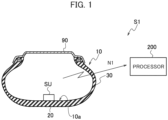
- a tire load prediction system S1 according to an embodiment of the present invention will be described with reference to FIGS. 1 and 2 .
- a schematic configuration of the tire load prediction system S1 according to the embodiment will be described with reference to the schematic configuration diagram of FIG. 1 .
- the tire load prediction system S1 uses a strain sensor SN instead of a conventional acceleration sensor, and follows an algorithm (the details of which are described later) to estimate the profile and deflection of a tire from single-axis (circumferential) data of the strain sensor SN and predict the load.
- the tire load prediction system S1 includes a sensor unit SU provided on a pneumatic tire (hereafter referred to simply as a tire) 10 side, and a processor 200 (in-vehicle device (ECU) or the like) that processes information acquired from the sensor unit SU via a wireless line N1.
- a processor 200 in-vehicle device (ECU) or the like
- FIG. 1 illustrates a cross-sectional shape along a tire width direction of a tire 10 mounted on a rim wheel 90.
- a tread portion 20 is a portion where the tire 10 attached to a vehicle (not illustrated) comes into contact with a road surface when rolling on the road surface.
- a tread pattern corresponding to the type of vehicle and the required performance is formed in the tread portion 20.
- the sensor unit SU provided with the single-axis strain sensor SN for detecting the strain of the tire 10 is provided on an inner surface 10a of the tire 10 to which the tire load prediction system S1 can be applied.
- the sensor unit SU may be capable of acquiring temperature information and the like in addition to the strain.
- the sensor unit SU is provided on the inner surface 10a facing the tread portion 20. More specifically, the sensor unit SU is attached to the surface of an inner liner (not illustrated) that prevents leakage of gases such as air filled in the internal space of the pneumatic tire 10 mounted on the rim wheel 90.
- the sensor unit SU is preferably provided on each tire 10 attached to the vehicle. This is because it is desirable to monitor the load or the like of each tire 10 so as to ensure the safety of the vehicle.
- the sensor unit SU need not necessarily be attached to the inner side surface of the tire 10.
- a part or all of the sensor unit SU may be embedded inside the tire 10.
- the sensor unit SU includes the single-axis strain sensor SN which detects strain of the tire 10, a transmitter 101 which transmits detection data to the processor 200, and a battery 102 which feeds the strain sensor SN and the transmitter 101.
- the processor 200 is provided with a strain data acquisition unit 202 that acquires, via a communication unit 201, strain data in a tire tangential direction that is output from the sensor unit SU.
- the processor 200 is provided with a storage unit 203 configured of a nonvolatile memory or the like for storing acquired strain data.
- the processor 200 is provided with a linear transformation unit 251 configured of a CPU 250 or the like for performing a linear transformation on acquired strain data.
- the processor 200 is provided with a first estimation unit 252 that estimates a velocity and angular velocity in the tire tangential direction on the basis of a transformation result produced by the linear transformation unit 251.
- the processor 200 is provided with a second estimation unit 253 that estimates a velocity in a tire radial direction from estimated values for the velocity and angular velocity in the tire tangential direction.
- the processor 200 is provided with a third estimation unit 254 that estimates a velocity in a ⁇ -angle direction corresponding to an angle of the strain sensor SN with respect to a ground contact surface of the tire 10, from estimated values for an acceleration and angular velocity in the tire tangential direction.
- the processor 200 is provided with a fourth estimation unit 255 that estimates deflection of the tire 10 on the basis of the velocity and angular velocity in the tire tangential direction, the velocity in the tire radial direction, and the velocity in the ⁇ -angle direction.
- the processor 200 is provided with a load prediction unit 256 that predicts a load applied to the tire 10 on the basis of the estimated deflection of the tire 10.
- linear transformation unit 251, the first estimation unit 252, the second estimation unit 253, the third estimation unit 254, the fourth estimation unit 255, and the load prediction unit 256 can be realized by cooperation between the CPU 250, an OS (operating system) stored in the storage unit 203 or the like, and a prescribed application program.
- OS operating system
- the details of the processing and the like carried out by the linear transformation unit 251, the first estimation unit 252, the second estimation unit 253, the third estimation unit 254, the fourth estimation unit 255, and the load prediction unit 256 are described later.
- FIGS. 3(a) to (d) Prior to describing the processing procedure for the tire load prediction processing, a definition of a coordinate system used in the tire load prediction system S1 according to the present embodiment is illustrated in FIGS. 3(a) to (d) .
- R is the radial direction (radial)
- T is the tangential direction (tangential) or circumferential direction (circumferential).
- the R, T coordinate system is an object coordinate system (local coordinate system) that is fixed on the strain sensor SN.
- x, z is a global coordinate system that is fixed in space. Furthermore, a represents acceleration, v represents velocity, and u represents displacement. In addition, ⁇ represents the angular velocity of the strain sensor SN, and ⁇ represents the angle of the strain sensor SN.
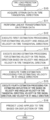
- FIG. 4 is a flow chart illustrating a processing procedure for tire load prediction processing executed in the tire load prediction system S1.
- step S10 strain data in the tire tangential direction is acquired, and the processing moves to step S11.
- step S11 a linear transformation is performed on the acquired strain data, and the processing moves to step S12.
- step S12 first estimation processing for estimating the velocity and angular velocity in the tire tangential direction is performed, and then the processing moves to step S13.
- step S13 second estimation processing for estimating the velocity in the tire radial direction on the basis of the velocity and angular velocity in the tire tangential direction is executed, and the processing moves to step S14.
- step S14 third estimation processing for estimating the velocity in the ⁇ -angle direction is executed, and the processing moves to step S15.
- Fourth estimation processing for estimating deflection of the tire 10 on the basis of the velocity and angular velocity in the tire tangential direction, the velocity in the tire radial direction, and the velocity in the ⁇ -angle direction is executed, and the processing moves to step S16.
- step S16 the load applied to the tire 10 is predicted based on the deflection of the tire 10, and the processing ends.
- a linear transformation is performed on measured strain data, and values for T-direction velocity and angular velocity are estimated.
- R-direction acceleration is estimated from these two estimated values. Then, by subjecting the R-direction acceleration to integration to obtain R-direction velocity, data of the three axes of "R-direction velocity”, “T-direction velocity”, and “ ⁇ -direction angular velocity” can be obtained. It then becomes possible to calculate the trajectory by using this data.
- this data is strain data at the tire inner surface as measured by the strain sensor SN, and is denoted as ⁇ (t) hereinafter.
- the angular velocity is estimated by performing a linear transformation on the measured data using the following formula (equation 1).
- ⁇ t ⁇ 0 a 1 ⁇ t + 1
- ⁇ 0 and a 1 are parameters representing the average angular velocity and an angular velocity multiplying factor, respectively.
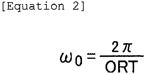
- ⁇ 0 2 ⁇ ORT
- a 1 is determined by learning from experimental values and so forth, by trial and error, or the like. Note that a nonlinear transformation may be used.
- a graph of the estimated angular velocity is illustrated as FIG. 6 .
- the tangential-direction velocity is estimated by performing a linear transformation on the measured data using the following formula (equation 3).
- v T t v T 0 a 2 ⁇ t + 1
- v T0 and a 2 are parameters representing the average tangential-direction velocity and a tangential-direction velocity multiplying factor, respectively.
- v T0 is obtained by means of the following formula (equation 4) using the one rotational time (ORT) obtained from the rotation cycle of the tire and the tire radius R.
- ORT one rotational time
- a 2 is determined by learning from experimental values and so forth, by trial and error, or the like. Note that a nonlinear transformation may be used.
- FIG. 7 A graph of the estimated tangential-direction velocity is illustrated as FIG. 7 .
- a R (t) may involve preprocessing such as centering in advance.
- the initial value of v R0 is set to any value.
- an estimated radial-direction velocity v R (t) and tangential-direction velocity v T (t) are transformed from the R, T coordinate system to the X, Z coordinate system using the estimated angular velocity ⁇ (t).
- co(t) may sometimes be subjected to preprocessing such as an adjustment for the average to become 2 ⁇ .
- the initial value ⁇ 0 is set to an appropriate value such as 0 or -n.
- v x and v z may involve preprocessing such as centering.
- the initial values u x0 and u z0 can be set to any values. Examples of calculation results are illustrated in the graphs of FIGS. 12 and 13 .
- an effective radius R eff (for example, the minimum value from the center of the regression circle) in a state where the tire is deflected is obtained.
- the feature value used for load prediction may be either of a deflection d and a deflection rate d/R fit .
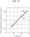
- FIG. 15 a relation between load and a deflection rate estimated value calculated using the algorithm in the present invention is illustrated in FIG. 15 . Note that this data is an example in which an analysis was performed similarly using FEM.
- the plot 10A indicates a tire with normal wear
- the plot 10B indicates a tire with uneven wear in the center.
- plots 10A and 10B almost converge to a single line.
- TPMS information in addition to deflection information, TPMS information, wear information, and the like can be used as explanatory variables, and the operation can be carried out with machine learning being performed to identify parameters in advance.
- linear multiple regression is basically sufficient, a nonlinear model may be used.
- strain sensor SN deflection and load of a tire can be predicted regardless of the wear condition of the tire.
- some of the processing functions of the processor 200 in the present embodiment may be mounted in the sensor unit SU.
Landscapes
- Engineering & Computer Science (AREA)
- Mechanical Engineering (AREA)
- Physics & Mathematics (AREA)
- General Physics & Mathematics (AREA)
- Chemical & Material Sciences (AREA)
- Analytical Chemistry (AREA)
- Tires In General (AREA)
- Force Measurement Appropriate To Specific Purposes (AREA)
Abstract
Description
- The present invention relates to a tire load prediction system, a tire load prediction program, and a tire load prediction method which predict a load of a pneumatic tire.
- In the past, a technique has been proposed in which the contact time ratio (CTR; parameter indicating ground contact length) of a tire is calculated using a time-series waveform of an acceleration sensor arranged inside a pneumatic tire (hereinafter referred to as a tire), to estimate the load of the tire on the basis of the contact time ratio (Patent Literature 1).
- Patent Literature 1:
Japanese Unexamined Patent Application Publication No. 2017-161477 - Incidentally, in the conventional technology, there has been an inconvenience in that load prediction errors are large because the ground contact length of a tire varies depending on the wear condition of the tire.
- Furthermore, acceleration sensors also have the disadvantage that the centrifugal force is small in the low-speed range, and it is therefore difficult to make a prediction with vehicles that mainly travel at low speeds.
- Thus, the present invention has been made in view of the above problems, and an object thereof is to provide a tire load prediction system, a tire load prediction program, and a tire load prediction method which can increase the accuracy of load prediction and can perform load prediction even for vehicles that mainly travel at low speeds.
- A tire load prediction system according to an aspect of the present invention includes: a sensor unit that is provided inside a tire and has a strain sensor that detects strain of the tire; a strain data acquisition unit that acquires strain data in a tire tangential direction that is output from the sensor unit; a linear transformation unit that performs a linear transformation on the acquired strain data; a first estimation unit that estimates a velocity and angular velocity in the tire tangential direction on the basis of a transformation result produced by the linear transformation unit; a second estimation unit that estimates a velocity in a tire radial direction from estimated values for the velocity and angular velocity in the tire tangential direction; a third estimation unit that estimates a velocity in a θ-angle direction corresponding to an angle of the strain sensor with respect to a ground contact surface of the tire, from estimated values for an acceleration and angular velocity in the tire tangential direction; a fourth estimation unit that estimates deflection of the tire on the basis of the velocity and angular velocity in the tire tangential direction, the velocity in the tire radial direction, and the velocity in the θ-angle direction; and a load prediction unit that predicts a load applied to the tire on the basis of the estimated deflection of the tire.
- According to such a configuration, it is possible to increase the accuracy of load prediction.
- Furthermore, it is possible for the fourth estimation unit to estimate a deformation profile of the tire on the basis of the velocity in the tire tangential direction, the velocity in the tire radial direction, and the velocity in the θ-angle direction, and extract a feature value corresponding to the deflection of the tire to estimate the deflection of the tire.
- It is thereby possible to further increase the accuracy of load prediction.
- Furthermore, it is possible for the linear transformation unit to perform a linear transformation on the strain data using the following formula.

- Wherein, ω0: average angular velocity, a1: angular velocity multiplying factor, ε: strain
- It is thereby possible to realize load prediction with increased accuracy.
- Furthermore, it is possible for the first estimation unit to estimate tangential-direction velocity by performing a linear transformation for the acquired data using the following formula.

- Wherein, vT0: average tangential-direction velocity, a2: tangential-direction velocity multiplying factor
- It is thereby possible to realize load prediction with increased accuracy.
- A tire load prediction program according to another aspect of the present invention is executed by a CPU provided in a tire load prediction system, the program including: a strain data acquisition step of acquiring strain data in a tire tangential direction that is output from a strain sensor provided on an inner side surface of a tire or inside the tire; a linear transformation step of performing a linear transformation on the acquired strain data; a first estimation step of estimating a velocity and angular velocity in the tire tangential direction on the basis of a transformation result; a second estimation step of estimating a velocity in a tire radial direction on the basis of estimated values for the velocity and angular velocity in the tire tangential direction; a third estimation step of estimating a velocity in a θ-angle direction corresponding to an angle of the strain sensor with respect to a ground contact surface of the tire, on the basis of estimated values for an acceleration and angular velocity in the tire tangential direction; a fourth estimation step of estimating deflection of the tire on the basis of the velocity and angular velocity in the tire tangential direction, the velocity in the tire radial direction, and the velocity in the θ-angle direction; and a load prediction step of predicting a load applied to the tire on the basis of the estimated deflection of the tire.
- It is thereby possible to increase the accuracy of load prediction.
- Furthermore, in the fourth estimation step, it is possible to estimate a deformation profile of the tire on the basis of the velocity in the tire tangential direction, the velocity in the tire radial direction, and the velocity in the θ-angle direction, and extract a feature value corresponding to the deflection of the tire to estimate the deflection of the tire.
- It is thereby possible to further increase the accuracy of load prediction.
- A tire load prediction method of another aspect of the present invention includes: a strain data acquisition process of acquiring strain data in a tire tangential direction that is output from a strain sensor provided on an inner side surface of a tire or inside the tire; a linear transformation process of performing a linear transformation on the acquired strain data; a first estimation process of estimating a velocity and angular velocity in the tire tangential direction on the basis of a transformation result; a second estimation process of estimating a velocity in a tire radial direction on the basis of estimated values for the velocity and angular velocity in the tire tangential direction; a third estimation process of estimating a velocity in a θ-angle direction corresponding to an angle of the strain sensor with respect to a ground contact surface of the tire, on the basis of estimated values for an acceleration and angular velocity in the tire tangential direction; a fourth estimation process of estimating deflection of the tire on the basis of the velocity and angular velocity in the tire tangential direction, the velocity in the tire radial direction, and the velocity in the θ-angle direction; and a load prediction process of predicting a load applied to the tire on the basis of the estimated deflection of the tire.
- It is thereby possible to increase the accuracy of load prediction.
- Furthermore, in the fourth estimation process, it is possible to estimate a deformation profile of the tire on the basis of the velocity in the tire tangential direction, the velocity in the tire radial direction, and the velocity in the θ-angle direction, and extract a feature value corresponding to the deflection of the tire to estimate the deflection of the tire.
- It is thereby possible to further increase the accuracy of load prediction.
- According to the present embodiment, it is possible to provide a tire load prediction system, a tire load prediction program, and a tire load prediction method which can increase the accuracy of load prediction and can perform load prediction even for vehicles that mainly travel at low speeds.
-
- [
FIG. 1] FIG. 1 is a schematic configuration diagram illustrating a schematic configuration of a tire load prediction system according to an embodiment. - [
FIG. 2] FIG. 2 is a functional block diagram illustrating a functional configuration of the tire load prediction system according to the embodiment. - [
FIG. 3] FIG. 3 consists of explanatory diagrams (a) to (d) illustrating a definition of a coordinate system used to explain the tire load prediction system according to the embodiment. - [
FIG. 4] FIG. 4 is a flow chart illustrating a processing procedure for tire load prediction processing executed in the tire load prediction system according to the embodiment. - [
FIG. 5] FIG. 5 is a graph illustrating a relation between tangential strain and time. - [
FIG. 6] FIG. 6 is a graph illustrating a relation between angular velocity and time. - [
FIG. 7] FIG. 7 is a graph illustrating a relation between tangential velocity and time. - [
FIG. 8] FIG. 8 consists of explanatory diagrams (a) to (c) used to explain a principle of estimating tangential-direction velocity. - [
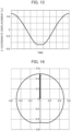
FIG. 9] FIG. 9 is a graph illustrating a relation between a sensor angle and time. - [
FIG. 10] FIG. 10 is a graph illustrating a relation between X-coordinate velocity and time. - [
FIG. 11] FIG. 11 is a graph illustrating a relation between Z-coordinate velocity and time. - [
FIG. 12] FIG. 12 is a graph illustrating a relation between X-coordinate displacement and time. - [
FIG. 13] FIG. 13 is a graph illustrating a relation between Z-coordinate displacement and time. - [
FIG. 14] FIG. 14 is a graph illustrating a tire deflection estimation situation. - [
FIG. 15] FIG. 15 is a graph illustrating a relation between a deflection rate estimation and load of a tire. - A tire load prediction system S1 according to an embodiment of the present invention will be described with reference to
FIGS. 1 and2 . - Note that the same or similar portions are denoted by the same or similar reference numerals in the following descriptions of the drawings. However, it should be noted that the drawings are schematic and ratios of dimensions and the like are different from the actual ones.
- Accordingly, specific dimensions and the like should be determined in consideration of the following descriptions. Furthermore, the drawings include portions having dimensional relations and ratios that are different from each other, as a matter of course.
- A schematic configuration of the tire load prediction system S1 according to the embodiment will be described with reference to the schematic configuration diagram of
FIG. 1 . - Here, the tire load prediction system S1 according to the present embodiment uses a strain sensor SN instead of a conventional acceleration sensor, and follows an algorithm (the details of which are described later) to estimate the profile and deflection of a tire from single-axis (circumferential) data of the strain sensor SN and predict the load.
- The tire load prediction system S1 includes a sensor unit SU provided on a pneumatic tire (hereafter referred to simply as a tire) 10 side, and a processor 200 (in-vehicle device (ECU) or the like) that processes information acquired from the sensor unit SU via a wireless line N1.
-
FIG. 1 illustrates a cross-sectional shape along a tire width direction of atire 10 mounted on arim wheel 90. - Furthermore, a
tread portion 20 is a portion where thetire 10 attached to a vehicle (not illustrated) comes into contact with a road surface when rolling on the road surface. A tread pattern corresponding to the type of vehicle and the required performance is formed in thetread portion 20. - The sensor unit SU provided with the single-axis strain sensor SN for detecting the strain of the
tire 10 is provided on aninner surface 10a of thetire 10 to which the tire load prediction system S1 can be applied. - Although not directly related to the present embodiment, note that the sensor unit SU may be capable of acquiring temperature information and the like in addition to the strain.
- In the configuration example illustrated in
FIG. 1 , the sensor unit SU is provided on theinner surface 10a facing thetread portion 20. More specifically, the sensor unit SU is attached to the surface of an inner liner (not illustrated) that prevents leakage of gases such as air filled in the internal space of thepneumatic tire 10 mounted on therim wheel 90. - The sensor unit SU is preferably provided on each
tire 10 attached to the vehicle. This is because it is desirable to monitor the load or the like of eachtire 10 so as to ensure the safety of the vehicle. - In addition, the sensor unit SU need not necessarily be attached to the inner side surface of the
tire 10. For example, a part or all of the sensor unit SU may be embedded inside thetire 10. - As illustrated in the functional block diagram of
FIG. 2 , the sensor unit SU includes the single-axis strain sensor SN which detects strain of thetire 10, atransmitter 101 which transmits detection data to theprocessor 200, and abattery 102 which feeds the strain sensor SN and thetransmitter 101. - Meanwhile, the
processor 200 is provided with a straindata acquisition unit 202 that acquires, via acommunication unit 201, strain data in a tire tangential direction that is output from the sensor unit SU. - Furthermore, the
processor 200 is provided with astorage unit 203 configured of a nonvolatile memory or the like for storing acquired strain data. - Furthermore, the
processor 200 is provided with alinear transformation unit 251 configured of aCPU 250 or the like for performing a linear transformation on acquired strain data. - In addition, the
processor 200 is provided with afirst estimation unit 252 that estimates a velocity and angular velocity in the tire tangential direction on the basis of a transformation result produced by thelinear transformation unit 251. - Furthermore, the
processor 200 is provided with asecond estimation unit 253 that estimates a velocity in a tire radial direction from estimated values for the velocity and angular velocity in the tire tangential direction. - Furthermore, the
processor 200 is provided with athird estimation unit 254 that estimates a velocity in a θ-angle direction corresponding to an angle of the strain sensor SN with respect to a ground contact surface of thetire 10, from estimated values for an acceleration and angular velocity in the tire tangential direction. - Furthermore, the
processor 200 is provided with afourth estimation unit 255 that estimates deflection of thetire 10 on the basis of the velocity and angular velocity in the tire tangential direction, the velocity in the tire radial direction, and the velocity in the θ-angle direction. - In addition, the
processor 200 is provided with aload prediction unit 256 that predicts a load applied to thetire 10 on the basis of the estimated deflection of thetire 10. - Note that the
linear transformation unit 251, thefirst estimation unit 252, thesecond estimation unit 253, thethird estimation unit 254, thefourth estimation unit 255, and theload prediction unit 256 can be realized by cooperation between theCPU 250, an OS (operating system) stored in thestorage unit 203 or the like, and a prescribed application program. - Furthermore, the details of the processing and the like carried out by the
linear transformation unit 251, thefirst estimation unit 252, thesecond estimation unit 253, thethird estimation unit 254, thefourth estimation unit 255, and theload prediction unit 256 are described later. - The processing procedure and so forth for the tire load prediction processing executed by the tire load prediction system S1 will be described with reference to
FIGS. 3 to 15 . - Prior to describing the processing procedure for the tire load prediction processing, a definition of a coordinate system used in the tire load prediction system S1 according to the present embodiment is illustrated in
FIGS. 3(a) to (d) . - Here, R is the radial direction (radial), and T is the tangential direction (tangential) or circumferential direction (circumferential).
- Furthermore, the R, T coordinate system is an object coordinate system (local coordinate system) that is fixed on the strain sensor SN.
- Meanwhile, x, z is a global coordinate system that is fixed in space. Furthermore, a represents acceleration, v represents velocity, and u represents displacement. In addition, ω represents the angular velocity of the strain sensor SN, and θ represents the angle of the strain sensor SN.
-
FIG. 4 is a flow chart illustrating a processing procedure for tire load prediction processing executed in the tire load prediction system S1. - When this processing is started, in step S10, strain data in the tire tangential direction is acquired, and the processing moves to step S11.
- In step S11, a linear transformation is performed on the acquired strain data, and the processing moves to step S12.
- In step S12, first estimation processing for estimating the velocity and angular velocity in the tire tangential direction is performed, and then the processing moves to step S13.
- In step S13, second estimation processing for estimating the velocity in the tire radial direction on the basis of the velocity and angular velocity in the tire tangential direction is executed, and the processing moves to step S14.
- In step S14, third estimation processing for estimating the velocity in the θ-angle direction is executed, and the processing moves to step S15.
- Fourth estimation processing for estimating deflection of the
tire 10 on the basis of the velocity and angular velocity in the tire tangential direction, the velocity in the tire radial direction, and the velocity in the θ-angle direction is executed, and the processing moves to step S16. - In step S16, the load applied to the
tire 10 is predicted based on the deflection of thetire 10, and the processing ends. - Here, a brief description will be given regarding a method of estimating load using biaxial acceleration for comparison.
- First, physically, the calculation to follow the motion of an object (rigid body) in two dimensions and obtain the trajectory thereof has three degrees of freedom, and in order to estimate the load on a tire using biaxial acceleration, data of the three axes of the "R-direction", "T-direction", and "θ-direction" is required.
- Therefore, with the assumption that the trajectory within the tire is mostly a circular motion, the acceleration in two axial directions (R, T) was measured, the angular velocity was estimated by calculation, and then processing to obtain the trajectory was performed.
- As a result of intensive research, the inventors of the present invention newly developed a method (algorithm) for how to estimate data in three axes ("R-direction", "T-direction", and "θ-direction") from measurement data of one axis, in order to realize the processing mentioned above with the single-axis strain sensor SN.
- In the method of predicting load in the present invention, first, a linear transformation is performed on measured strain data, and values for T-direction velocity and angular velocity are estimated.
- Next, R-direction acceleration is estimated from these two estimated values. Then, by subjecting the R-direction acceleration to integration to obtain R-direction velocity, data of the three axes of "R-direction velocity", "T-direction velocity", and "θ-direction angular velocity" can be obtained. It then becomes possible to calculate the trajectory by using this data.
- The details of the calculation method will be described below following the procedure.
- Note that here, for the convenience of the explanation, the sample data illustrated in
FIG. 5 shall be used. This data was obtained by means of FEM analysis, and the tire type is "11R22.5M801". - Furthermore, this data is strain data at the tire inner surface as measured by the strain sensor SN, and is denoted as ε(t) hereinafter.
- First, the process of calculating angular velocity from tangential-direction strain will be described.
- The angular velocity is estimated by performing a linear transformation on the measured data using the following formula (equation 1).

- Wherein, ω0 and a1 are parameters representing the average angular velocity and an angular velocity multiplying factor, respectively.
- Note that ω0 is obtained by means of the following formula (equation 2) using the one rotational time (ORT) obtained from the rotation cycle of the tire.
- Furthermore, a1 is determined by learning from experimental values and so forth, by trial and error, or the like. Note that a nonlinear transformation may be used.
- A graph of the estimated angular velocity is illustrated as
FIG. 6 . - In the
tire 10, large bending deformation occurs in regions near the ground contact edge, and large compressive strain at the tire inner surface occurs. - Furthermore, it is thought that the curvature increases due to the large bending deformation, and that the angular velocity of the strain sensor SN itself increases.
- Conversely, it is thought that, in the vicinity of directly below the axle, the bending deformation lessens, the compressive strain decreases (becomes a tensile force), and furthermore the curvature decreases, and as a result the angular velocity of the strain sensor SN itself also decreases.
- Therefore, there is a correlation between the compressive strain and the angular velocity of the strain sensor SN, which is assumed here to be linear.
- Next, the process of calculating tangential-direction velocity from tangential-direction strain will be described.
- The tangential-direction velocity is estimated by performing a linear transformation on the measured data using the following formula (equation 3).

- Wherein, vT0 and a2 are parameters representing the average tangential-direction velocity and a tangential-direction velocity multiplying factor, respectively.
- Note that vT0 is obtained by means of the following formula (equation 4) using the one rotational time (ORT) obtained from the rotation cycle of the tire and the tire radius R.

- Furthermore, a2 is determined by learning from experimental values and so forth, by trial and error, or the like. Note that a nonlinear transformation may be used.
- A graph of the estimated tangential-direction velocity is illustrated as
FIG. 7 . - It is assumed that the rolling
tire 10 is divided in terms of space for each very short sampling time interval Δt, as illustrated inFIG. 8(a) . - Here, in the case of a pre-deformed state of the tire 10 (tire rotating in midair), a time-independent radius R0 and an angular velocity ω0 are assumed, and the distance traveled in a very short time can be written as R0ω0Δt (see
FIG. 8(b) ). - On the other hand, when the
tire 10 is in contact with the ground and deformation has occurred, the radius and angular velocity are functions of time and are expressed as R(t) and θ'(t), respectively. Here, the distance traveled in a very short time can be written as R(t)θ'(t)Δt (seeFIG. 8(c) ). - Since the definition of strain is the extent to which expansion or contraction has occurred with respect to original length, the circumferential-direction strain of the
tire 10 is expressed by the following formula (equation 5).
- Here, assuming that the strain sensor SN is in circular motion, the tangential-direction velocity vT(t) can be written as the following formula (equation 6).

- Substituting this into the formula for ε(t) of equation 6 obtains equation 7.

- Here, since R0ω0 is a time-independent fixed value, it can be seen that vT(t) and ε(t) have a linear transformation relation.
- Assuming that the strain sensor SN is in circular motion, theoretically the estimation is performed by means of the calculation of the following formula (equation 8).

- Furthermore, velocity in the radial direction is calculated by integrating the estimated value with respect to time using the following formula (equation 9).

- However, aR(t) may involve preprocessing such as centering in advance. Furthermore, the initial value of vR0 is set to any value.
- Here, an estimated radial-direction velocity vR(t) and tangential-direction velocity vT(t) are transformed from the R, T coordinate system to the X, Z coordinate system using the estimated angular velocity ω(t).
- First, the angular velocity w(t) is integrated and the angle θ(t) is calculated using the following formula (equation 10).

- However, co(t) may sometimes be subjected to preprocessing such as an adjustment for the average to become 2π. The initial value θ0 is set to an appropriate value such as 0 or -n.
- An example of the calculation result for the angle θ(t) is illustrated in the graph of
FIG. 9 . - Next, a coordinate transformation for velocity is performed.
- A calculation from the object coordinate system (R, T) of the strain sensor SN to the global coordinate system (x, z) is performed using the following formula (equation 11).

- Examples of calculation results are illustrated in the graphs of
FIGS. 10 and11 . - The velocity is integrated and displacements ux(t) and uz(t) are calculated from the following formula (equation 12).

- However, vx and vz may involve preprocessing such as centering. The initial values ux0 and uz0 can be set to any values. Examples of calculation results are illustrated in the graphs of
FIGS. 12 and13 . - Then, when illustrated on a two-dimensional plane, the displacement (ux(t), uz(t)) excluding the time component becomes the trajectory illustrated in
FIG. 14 . A circle is fitted to this trajectory, and a regression radius Rfit is obtained. - Furthermore, an effective radius Reff (for example, the minimum value from the center of the regression circle) in a state where the tire is deflected is obtained.
- The deflection is then calculated using the following formula (equation 13).

- Note that the feature value used for load prediction may be either of a deflection d and a deflection rate d/Rfit.
- Next, the validity of a load calculation using deflection and the method therefor will be presented.
- First, a relation between load and a deflection rate estimated value calculated using the algorithm in the present invention is illustrated in
FIG. 15 . Note that this data is an example in which an analysis was performed similarly using FEM. - Furthermore, in
FIG. 15 , theplot 10A indicates a tire with normal wear, and theplot 10B indicates a tire with uneven wear in the center. - In this way, a linear relation is obtained similar to the deflection obtained from the aforementioned axle height.
- Furthermore, as illustrated in
FIG. 15 , it can be seen thatplots - Wear dependence, which has been a disadvantage of CTR as previously mentioned, is not observed, and it is therefore possible to achieve greater accuracy in load prediction.
- Furthermore, when actually performing load prediction, the load is calculated using the following formula (equation 14) .

- Note that, in addition to deflection information, TPMS information, wear information, and the like can be used as explanatory variables, and the operation can be carried out with machine learning being performed to identify parameters in advance.
- Furthermore, although linear multiple regression is basically sufficient, a nonlinear model may be used.
- As described above, with the tire load prediction system S1 according to the present embodiment, it is possible to increase the accuracy of load prediction, and it is possible to perform load prediction even for vehicles that mainly travel at low speeds.
- Furthermore, by using the strain sensor SN, deflection and load of a tire can be predicted regardless of the wear condition of the tire.
- The tire load prediction system and tire load prediction program of the present invention have been described above based on the illustrated embodiment; however, the present invention is not limited to the present embodiment, and the configuration of each part can be replaced with any other configurations having equivalent functions.
- For example, if operating conditions of the power supply (battery) 102 and so forth are satisfied, some of the processing functions of the
processor 200 in the present embodiment may be mounted in the sensor unit SU. -
- S1
- Tire load prediction system
- SU
- Sensor unit
- SN
- Strain sensor
- 10
- Pneumatic tire (tire)
- 200
- Processor
- 202
- Data acquisition unit
- 203
- Storage unit
- 250
- CPU
- 251
- Linear transformation unit
- 252
- First estimation unit
- 253
- Second estimation unit
- 254
- Third estimation unit
- 255
- Fourth estimation unit
- 256
- Load prediction unit
Claims (8)
- A tire load prediction system comprising:a sensor unit that is provided inside a tire and has a strain sensor that detects strain of the tire;a strain data acquisition unit that acquires strain data in a tire tangential direction that is output from the sensor unit;a linear transformation unit that performs a linear transformation on the acquired strain data;a first estimation unit that estimates a velocity and angular velocity in the tire tangential direction on the basis of a transformation result produced by the linear transformation unit;a second estimation unit that estimates a velocity in a tire radial direction from estimated values for the velocity and angular velocity in the tire tangential direction;a third estimation unit that estimates a velocity in a θ-angle direction corresponding to an angle of the strain sensor with respect to a ground contact surface of the tire, from estimated values for an acceleration and angular velocity in the tire tangential direction;a fourth estimation unit that estimates deflection of the tire on the basis of the velocity and angular velocity in the tire tangential direction, the velocity in the tire radial direction, and the velocity in the θ-angle direction; anda load prediction unit that predicts a load applied to the tire on the basis of the estimated deflection of the tire.
- The tire load prediction system according to claim 1, wherein
the fourth estimation unit estimates a deformation profile of the tire on the basis of the velocity in the tire tangential direction, the velocity in the tire radial direction, and the velocity in the θ-angle direction, and extracts a feature value corresponding to the deflection of the tire to estimate the deflection of the tire. - The tire load prediction system according to claim 1, whereinthe linear transformation unit performs a linear transformation on the strain data using the following formula.
 Wherein, ω0: average angular velocity, a1: angular velocity multiplying factor, ε: strain
- The tire load prediction system according to claim 1, whereinthe first estimation unit estimates tangential-direction velocity by performing a linear transformation for the acquired data using the following formula.
 Wherein, vT0: average tangential-direction velocity, az: tangential-direction velocity multiplying factor
- A tire load prediction program executed by a CPU provided in a tire load prediction system, the program comprising:a strain data acquisition step of acquiring strain data in a tire tangential direction that is output from a strain sensor provided on an inner side surface of a tire or inside the tire;a linear transformation step of performing a linear transformation on the acquired strain data;a first estimation step of estimating a velocity and angular velocity in the tire tangential direction on the basis of a transformation result;a second estimation step of estimating a velocity in a tire radial direction on the basis of estimated values for the velocity and angular velocity in the tire tangential direction;a third estimation step of estimating a velocity in a θ-angle direction corresponding to an angle of the strain sensor with respect to a ground contact surface of the tire, on the basis of estimated values for an acceleration and angular velocity in the tire tangential direction;a fourth estimation step of estimating deflection of the tire on the basis of the velocity and angular velocity in the tire tangential direction, the velocity in the tire radial direction, and the velocity in the θ-angle direction; anda load prediction step of predicting a load applied to the tire on the basis of the estimated deflection of the tire.
- The tire load prediction program according to claim 5, wherein
in the fourth estimation step, a deformation profile of the tire is estimated based on the velocity in the tire tangential direction, the velocity in the tire radial direction, and the velocity in the θ-angle direction, and a feature value corresponding to the deflection of the tire is extracted to estimate the deflection of the tire. - A tire load prediction method comprising:a strain data acquisition process of acquiring strain data in a tire tangential direction that is output from a strain sensor provided on an inner side surface of a tire or inside the tire;a linear transformation process of performing a linear transformation on the acquired strain data;a first estimation process of estimating a velocity and angular velocity in the tire tangential direction on the basis of a transformation result;a second estimation process of estimating a velocity in a tire radial direction on the basis of estimated values for the velocity and angular velocity in the tire tangential direction;a third estimation process of estimating a velocity in a θ-angle direction corresponding to an angle of the strain sensor with respect to a ground contact surface of the tire, on the basis of estimated values for an acceleration and angular velocity in the tire tangential direction;a fourth estimation process of estimating deflection of the tire on the basis of the velocity and angular velocity in the tire tangential direction, the velocity in the tire radial direction, and the velocity in the θ-angle direction; anda load prediction process of predicting a load applied to the tire on the basis of the estimated deflection of the tire.
- The tire load prediction method according to claim 7, wherein
in the fourth estimation process, a deformation profile of the tire is estimated based on the velocity in the tire tangential direction, the velocity in the tire radial direction, and the velocity in the θ-angle direction, and a feature value corresponding to the deflection of the tire is extracted to estimate the deflection of the tire.
Applications Claiming Priority (2)
| Application Number | Priority Date | Filing Date | Title |
|---|---|---|---|
| JP2020187996A JP7407098B2 (en) | 2020-11-11 | 2020-11-11 | Tire load prediction system, tire load prediction program, and tire load prediction method |
| PCT/JP2021/040419 WO2022102473A1 (en) | 2020-11-11 | 2021-11-02 | Tire load predicting system, tire load predicting program, and tire load predicting method |
Publications (3)
| Publication Number | Publication Date |
|---|---|
| EP4246112A1 true EP4246112A1 (en) | 2023-09-20 |
| EP4246112A4 EP4246112A4 (en) | 2024-04-24 |
| EP4246112B1 EP4246112B1 (en) | 2025-03-26 |
Family
ID=81601184
Family Applications (1)
| Application Number | Title | Priority Date | Filing Date |
|---|---|---|---|
| EP21891720.1A Active EP4246112B1 (en) | 2020-11-11 | 2021-11-02 | Tire load prediction system, tire load prediction program, and tire load prediction method |
Country Status (5)
| Country | Link |
|---|---|
| US (1) | US20230406048A1 (en) |
| EP (1) | EP4246112B1 (en) |
| JP (1) | JP7407098B2 (en) |
| CN (1) | CN116569012B (en) |
| WO (1) | WO2022102473A1 (en) |
Families Citing this family (1)
| Publication number | Priority date | Publication date | Assignee | Title |
|---|---|---|---|---|
| WO2023152986A1 (en) * | 2022-02-14 | 2023-08-17 | 日立Astemo株式会社 | Road-surface type detection device |
Family Cites Families (12)
| Publication number | Priority date | Publication date | Assignee | Title |
|---|---|---|---|---|
| US20030058118A1 (en) * | 2001-05-15 | 2003-03-27 | Wilson Kitchener C. | Vehicle and vehicle tire monitoring system, apparatus and method |
| JP4517610B2 (en) * | 2003-09-16 | 2010-08-04 | トヨタ自動車株式会社 | Tire state quantity detection device |
| WO2005042281A1 (en) | 2003-10-24 | 2005-05-12 | Pirelli Pneumatici S.P.A. | Method and system for determining a tyre load during the running of a vehicle |
| JP4680532B2 (en) * | 2004-06-02 | 2011-05-11 | 株式会社ブリヂストン | Method and apparatus for estimating dynamic state of tire |
| CN1977156B (en) * | 2004-06-30 | 2010-12-08 | 米其林技术公司 | Estimation of maximum grip coefficient based on measuring stress in tire tread |
| ATE447702T1 (en) | 2005-05-30 | 2009-11-15 | Interfleet Technology Ab | METHOD AND SYSTEM FOR DETERMINING SEVERAL LOAD COMPONENTS ON A WHEEL |
| DE102008046269B3 (en) * | 2008-09-08 | 2009-12-24 | Continental Automotive Gmbh | Wheel load determining method for passenger car, involves comparing calculated wheel load with detected wheel load, and performing adaptation of equations and/or equation parameters based on comparison |
| ES2363400B2 (en) | 2011-03-03 | 2011-12-20 | Universidad Politécnica de Madrid | METHOD AND ESTIMATION SYSTEM OF EFFORTS GENERATED BY THE TIRE CONTACT WITH THE SHOE IN AN INSTRUMENTALIZED RIM. |
| US9120356B2 (en) | 2012-06-27 | 2015-09-01 | The Goodyear Tire & Rubber Company | Load estimation system and method for a vehicle tire |
| JP2017161477A (en) | 2016-03-11 | 2017-09-14 | 株式会社ブリヂストン | Tire load estimation method and tire load estimation device |
| JP6830873B2 (en) * | 2017-09-11 | 2021-02-17 | 株式会社ブリヂストン | Tire load estimation method and tire load estimation device |
| US12054015B2 (en) * | 2017-11-24 | 2024-08-06 | Pirelli Tyre S.P.A. | Method and system for monitoring a parameter related to a tire during the running of a vehicle |
-
2020
- 2020-11-11 JP JP2020187996A patent/JP7407098B2/en active Active
-
2021
- 2021-11-02 US US18/035,954 patent/US20230406048A1/en active Pending
- 2021-11-02 WO PCT/JP2021/040419 patent/WO2022102473A1/en not_active Ceased
- 2021-11-02 CN CN202180075588.5A patent/CN116569012B/en active Active
- 2021-11-02 EP EP21891720.1A patent/EP4246112B1/en active Active
Also Published As
| Publication number | Publication date |
|---|---|
| CN116569012A (en) | 2023-08-08 |
| JP2022077234A (en) | 2022-05-23 |
| US20230406048A1 (en) | 2023-12-21 |
| EP4246112A4 (en) | 2024-04-24 |
| EP4246112B1 (en) | 2025-03-26 |
| WO2022102473A1 (en) | 2022-05-19 |
| JP7407098B2 (en) | 2023-12-28 |
| CN116569012B (en) | 2025-09-09 |
Similar Documents
| Publication | Publication Date | Title |
|---|---|---|
| EP3674159B1 (en) | Arithmetic model generation system and arithmetic model generation method | |
| EP2837510B1 (en) | Torsional mode tire wear state estimation system and method | |
| US10328755B2 (en) | Method and system for estimating the load acting on a tire | |
| EP4124842B1 (en) | Method for estimating tire wear and method for determining tire wear shape | |
| US8833151B2 (en) | Method and system for estimating the inflation pressure of a tire | |
| EP2740640B1 (en) | Tire slip angle estimation system and method | |
| EP2705963A2 (en) | Tire sidewall load estimation system and method | |
| CN111433054B (en) | Method and system for monitoring tire-related parameters during vehicle operation | |
| Sun et al. | Direct tire slip angle estimation using intelligent tire equipped with PVDF sensors | |
| EP4246112B1 (en) | Tire load prediction system, tire load prediction program, and tire load prediction method | |
| US8165827B2 (en) | Method for calculating forces acting on the footprint area of a tyre and apparatus for calculating said forces | |
| Breglio et al. | Feel-tire unina: development and modeling of a sensing system for intelligent tires | |
| KR102149458B1 (en) | System and method for mornitoring condition of tire and road surface during vehicle driving | |
| CN117098678B (en) | Calibration method and system for sensors used in tires | |
| Wang et al. | Tire rolling kinematics model for an intelligent tire based on an accelerometer | |
| EP4246117B1 (en) | Tire wear condition prediction system, tire wear condition prediction program and tire wear condition prediction method | |
| Nishiyama et al. | Intelligent tire algorithm enabling simultaneous detection of loading and wear status of truck and bus tires | |
| WO2025141453A1 (en) | Method and system for estimating the state of a road surface | |
| Cherukuri | Intelligent tire based tire force characterization and its application in vehicle stability and performance | |
| Mengyao et al. | Novel technology for acquiring wheel motion attitude information based on WEIS | |
| García-Pozuelo Ramos et al. | A Novel Strain-Based Method to Estimate Tire Conditions Using Fuzzy Logic for Intelligent Tires | |
| Yunta Ramírez et al. | A Strain-Based Method to Detect Tires' Loss of Grip and Estimate Lateral Friction Coefficient from Experimental Data by Fuzzy Logic for Intelligent Tire Development |
Legal Events
| Date | Code | Title | Description |
|---|---|---|---|
| STAA | Information on the status of an ep patent application or granted ep patent |
Free format text: STATUS: THE INTERNATIONAL PUBLICATION HAS BEEN MADE |
|
| PUAI | Public reference made under article 153(3) epc to a published international application that has entered the european phase |
Free format text: ORIGINAL CODE: 0009012 |
|
| STAA | Information on the status of an ep patent application or granted ep patent |
Free format text: STATUS: REQUEST FOR EXAMINATION WAS MADE |
|
| 17P | Request for examination filed |
Effective date: 20230512 |
|
| AK | Designated contracting states |
Kind code of ref document: A1 Designated state(s): AL AT BE BG CH CY CZ DE DK EE ES FI FR GB GR HR HU IE IS IT LI LT LU LV MC MK MT NL NO PL PT RO RS SE SI SK SM TR |
|
| DAV | Request for validation of the european patent (deleted) | ||
| DAX | Request for extension of the european patent (deleted) | ||
| REG | Reference to a national code |
Ref country code: DE Ref legal event code: R079 Free format text: PREVIOUS MAIN CLASS: G01L0005000000 Ipc: B60C0023060000 Ref document number: 602021028308 Country of ref document: DE |
|
| A4 | Supplementary search report drawn up and despatched |
Effective date: 20240321 |
|
| RIC1 | Information provided on ipc code assigned before grant |
Ipc: G01M 17/02 20060101ALI20240318BHEP Ipc: G01L 1/04 20060101ALI20240318BHEP Ipc: G01B 7/16 20060101ALI20240318BHEP Ipc: B60C 23/06 20060101AFI20240318BHEP |
|
| GRAP | Despatch of communication of intention to grant a patent |
Free format text: ORIGINAL CODE: EPIDOSNIGR1 |
|
| STAA | Information on the status of an ep patent application or granted ep patent |
Free format text: STATUS: GRANT OF PATENT IS INTENDED |
|
| RIC1 | Information provided on ipc code assigned before grant |
Ipc: B60C 19/00 20060101ALI20240926BHEP Ipc: G01M 17/02 20060101ALI20240926BHEP Ipc: G01L 1/04 20060101ALI20240926BHEP Ipc: G01B 21/32 20060101ALI20240926BHEP Ipc: B60C 23/06 20060101AFI20240926BHEP |
|
| INTG | Intention to grant announced |
Effective date: 20241015 |
|
| P01 | Opt-out of the competence of the unified patent court (upc) registered |
Free format text: CASE NUMBER: APP_454/2025 Effective date: 20250106 |
|
| GRAS | Grant fee paid |
Free format text: ORIGINAL CODE: EPIDOSNIGR3 |
|
| GRAA | (expected) grant |
Free format text: ORIGINAL CODE: 0009210 |
|
| STAA | Information on the status of an ep patent application or granted ep patent |
Free format text: STATUS: THE PATENT HAS BEEN GRANTED |
|
| AK | Designated contracting states |
Kind code of ref document: B1 Designated state(s): AL AT BE BG CH CY CZ DE DK EE ES FI FR GB GR HR HU IE IS IT LI LT LU LV MC MK MT NL NO PL PT RO RS SE SI SK SM TR |
|
| REG | Reference to a national code |
Ref country code: GB Ref legal event code: FG4D |
|
| REG | Reference to a national code |
Ref country code: CH Ref legal event code: EP |
|
| REG | Reference to a national code |
Ref country code: DE Ref legal event code: R096 Ref document number: 602021028308 Country of ref document: DE |
|
| REG | Reference to a national code |
Ref country code: IE Ref legal event code: FG4D |
|
| PG25 | Lapsed in a contracting state [announced via postgrant information from national office to epo] |
Ref country code: RS Free format text: LAPSE BECAUSE OF FAILURE TO SUBMIT A TRANSLATION OF THE DESCRIPTION OR TO PAY THE FEE WITHIN THE PRESCRIBED TIME-LIMIT Effective date: 20250626 |
|
| PG25 | Lapsed in a contracting state [announced via postgrant information from national office to epo] |
Ref country code: FI Free format text: LAPSE BECAUSE OF FAILURE TO SUBMIT A TRANSLATION OF THE DESCRIPTION OR TO PAY THE FEE WITHIN THE PRESCRIBED TIME-LIMIT Effective date: 20250326 |
|
| REG | Reference to a national code |
Ref country code: LT Ref legal event code: MG9D |
|
| PG25 | Lapsed in a contracting state [announced via postgrant information from national office to epo] |
Ref country code: NO Free format text: LAPSE BECAUSE OF FAILURE TO SUBMIT A TRANSLATION OF THE DESCRIPTION OR TO PAY THE FEE WITHIN THE PRESCRIBED TIME-LIMIT Effective date: 20250626 |
|
| PG25 | Lapsed in a contracting state [announced via postgrant information from national office to epo] |
Ref country code: HR Free format text: LAPSE BECAUSE OF FAILURE TO SUBMIT A TRANSLATION OF THE DESCRIPTION OR TO PAY THE FEE WITHIN THE PRESCRIBED TIME-LIMIT Effective date: 20250326 |
|
| PG25 | Lapsed in a contracting state [announced via postgrant information from national office to epo] |
Ref country code: LV Free format text: LAPSE BECAUSE OF FAILURE TO SUBMIT A TRANSLATION OF THE DESCRIPTION OR TO PAY THE FEE WITHIN THE PRESCRIBED TIME-LIMIT Effective date: 20250326 |
|
| PG25 | Lapsed in a contracting state [announced via postgrant information from national office to epo] |
Ref country code: BG Free format text: LAPSE BECAUSE OF FAILURE TO SUBMIT A TRANSLATION OF THE DESCRIPTION OR TO PAY THE FEE WITHIN THE PRESCRIBED TIME-LIMIT Effective date: 20250326 Ref country code: GR Free format text: LAPSE BECAUSE OF FAILURE TO SUBMIT A TRANSLATION OF THE DESCRIPTION OR TO PAY THE FEE WITHIN THE PRESCRIBED TIME-LIMIT Effective date: 20250627 |
|
| REG | Reference to a national code |
Ref country code: NL Ref legal event code: MP Effective date: 20250326 |
|
| PG25 | Lapsed in a contracting state [announced via postgrant information from national office to epo] |
Ref country code: NL Free format text: LAPSE BECAUSE OF FAILURE TO SUBMIT A TRANSLATION OF THE DESCRIPTION OR TO PAY THE FEE WITHIN THE PRESCRIBED TIME-LIMIT Effective date: 20250326 |
|
| PG25 | Lapsed in a contracting state [announced via postgrant information from national office to epo] |
Ref country code: SE Free format text: LAPSE BECAUSE OF FAILURE TO SUBMIT A TRANSLATION OF THE DESCRIPTION OR TO PAY THE FEE WITHIN THE PRESCRIBED TIME-LIMIT Effective date: 20250326 |
|
| REG | Reference to a national code |
Ref country code: AT Ref legal event code: MK05 Ref document number: 1778724 Country of ref document: AT Kind code of ref document: T Effective date: 20250326 |
|
| PG25 | Lapsed in a contracting state [announced via postgrant information from national office to epo] |
Ref country code: SM Free format text: LAPSE BECAUSE OF FAILURE TO SUBMIT A TRANSLATION OF THE DESCRIPTION OR TO PAY THE FEE WITHIN THE PRESCRIBED TIME-LIMIT Effective date: 20250326 |
|
| PG25 | Lapsed in a contracting state [announced via postgrant information from national office to epo] |
Ref country code: PT Free format text: LAPSE BECAUSE OF FAILURE TO SUBMIT A TRANSLATION OF THE DESCRIPTION OR TO PAY THE FEE WITHIN THE PRESCRIBED TIME-LIMIT Effective date: 20250728 Ref country code: ES Free format text: LAPSE BECAUSE OF FAILURE TO SUBMIT A TRANSLATION OF THE DESCRIPTION OR TO PAY THE FEE WITHIN THE PRESCRIBED TIME-LIMIT Effective date: 20250326 |
|
| PG25 | Lapsed in a contracting state [announced via postgrant information from national office to epo] |
Ref country code: IT Free format text: LAPSE BECAUSE OF FAILURE TO SUBMIT A TRANSLATION OF THE DESCRIPTION OR TO PAY THE FEE WITHIN THE PRESCRIBED TIME-LIMIT Effective date: 20250326 Ref country code: PL Free format text: LAPSE BECAUSE OF FAILURE TO SUBMIT A TRANSLATION OF THE DESCRIPTION OR TO PAY THE FEE WITHIN THE PRESCRIBED TIME-LIMIT Effective date: 20250326 |
|
| PG25 | Lapsed in a contracting state [announced via postgrant information from national office to epo] |
Ref country code: AT Free format text: LAPSE BECAUSE OF FAILURE TO SUBMIT A TRANSLATION OF THE DESCRIPTION OR TO PAY THE FEE WITHIN THE PRESCRIBED TIME-LIMIT Effective date: 20250326 |
|
| PG25 | Lapsed in a contracting state [announced via postgrant information from national office to epo] |
Ref country code: EE Free format text: LAPSE BECAUSE OF FAILURE TO SUBMIT A TRANSLATION OF THE DESCRIPTION OR TO PAY THE FEE WITHIN THE PRESCRIBED TIME-LIMIT Effective date: 20250326 |
|
| PG25 | Lapsed in a contracting state [announced via postgrant information from national office to epo] |
Ref country code: RO Free format text: LAPSE BECAUSE OF FAILURE TO SUBMIT A TRANSLATION OF THE DESCRIPTION OR TO PAY THE FEE WITHIN THE PRESCRIBED TIME-LIMIT Effective date: 20250326 |
|
| PG25 | Lapsed in a contracting state [announced via postgrant information from national office to epo] |
Ref country code: SK Free format text: LAPSE BECAUSE OF FAILURE TO SUBMIT A TRANSLATION OF THE DESCRIPTION OR TO PAY THE FEE WITHIN THE PRESCRIBED TIME-LIMIT Effective date: 20250326 |
|
| PG25 | Lapsed in a contracting state [announced via postgrant information from national office to epo] |
Ref country code: IS Free format text: LAPSE BECAUSE OF FAILURE TO SUBMIT A TRANSLATION OF THE DESCRIPTION OR TO PAY THE FEE WITHIN THE PRESCRIBED TIME-LIMIT Effective date: 20250726 |
|
| REG | Reference to a national code |
Ref country code: DE Ref legal event code: R097 Ref document number: 602021028308 Country of ref document: DE |
|
| PGFP | Annual fee paid to national office [announced via postgrant information from national office to epo] |
Ref country code: DE Payment date: 20251119 Year of fee payment: 5 |
|
| PG25 | Lapsed in a contracting state [announced via postgrant information from national office to epo] |
Ref country code: DK Free format text: LAPSE BECAUSE OF FAILURE TO SUBMIT A TRANSLATION OF THE DESCRIPTION OR TO PAY THE FEE WITHIN THE PRESCRIBED TIME-LIMIT Effective date: 20250326 |
|
| PGFP | Annual fee paid to national office [announced via postgrant information from national office to epo] |
Ref country code: FR Payment date: 20251126 Year of fee payment: 5 |
|
| PG25 | Lapsed in a contracting state [announced via postgrant information from national office to epo] |
Ref country code: CZ Free format text: LAPSE BECAUSE OF FAILURE TO SUBMIT A TRANSLATION OF THE DESCRIPTION OR TO PAY THE FEE WITHIN THE PRESCRIBED TIME-LIMIT Effective date: 20250326 |
|
| PLBE | No opposition filed within time limit |
Free format text: ORIGINAL CODE: 0009261 |
|
| STAA | Information on the status of an ep patent application or granted ep patent |
Free format text: STATUS: NO OPPOSITION FILED WITHIN TIME LIMIT |
|
| REG | Reference to a national code |
Ref country code: CH Ref legal event code: L10 Free format text: ST27 STATUS EVENT CODE: U-0-0-L10-L00 (AS PROVIDED BY THE NATIONAL OFFICE) Effective date: 20260211 |
|
| 26N | No opposition filed |
Effective date: 20260105 |
|
| REG | Reference to a national code |
Ref country code: CH Ref legal event code: H13 Free format text: ST27 STATUS EVENT CODE: U-0-0-H10-H13 (AS PROVIDED BY THE NATIONAL OFFICE) Effective date: 20260623 |
|
| PG25 | Lapsed in a contracting state [announced via postgrant information from national office to epo] |
Ref country code: LT Free format text: LAPSE BECAUSE OF FAILURE TO SUBMIT A TRANSLATION OF THE DESCRIPTION OR TO PAY THE FEE WITHIN THE PRESCRIBED TIME-LIMIT Effective date: 20250326 |
|
| PG25 | Lapsed in a contracting state [announced via postgrant information from national office to epo] |
Ref country code: MC Free format text: LAPSE BECAUSE OF FAILURE TO SUBMIT A TRANSLATION OF THE DESCRIPTION OR TO PAY THE FEE WITHIN THE PRESCRIBED TIME-LIMIT Effective date: 20250326 |
|
| PG25 | Lapsed in a contracting state [announced via postgrant information from national office to epo] |
Ref country code: LU Free format text: LAPSE BECAUSE OF NON-PAYMENT OF DUE FEES Effective date: 20251102 Ref country code: CH Free format text: LAPSE BECAUSE OF NON-PAYMENT OF DUE FEES Effective date: 20251130 |