EP4246105A1 - Combination weighing apparatus - Google Patents
Combination weighing apparatus Download PDFInfo
- Publication number
- EP4246105A1 EP4246105A1 EP23161985.9A EP23161985A EP4246105A1 EP 4246105 A1 EP4246105 A1 EP 4246105A1 EP 23161985 A EP23161985 A EP 23161985A EP 4246105 A1 EP4246105 A1 EP 4246105A1
- Authority
- EP
- European Patent Office
- Prior art keywords
- article
- articles
- dispersion table
- weighing apparatus
- combination weighing
- Prior art date
- Legal status (The legal status is an assumption and is not a legal conclusion. Google has not performed a legal analysis and makes no representation as to the accuracy of the status listed.)
- Granted
Links
Images



Classifications
-
- G—PHYSICS
- G01—MEASURING; TESTING
- G01G—WEIGHING
- G01G23/00—Auxiliary devices for weighing apparatus
-
- G—PHYSICS
- G01—MEASURING; TESTING
- G01G—WEIGHING
- G01G13/00—Weighing apparatus with automatic feed or discharge for weighing-out batches of material
- G01G13/16—Means for automatically discharging weigh receptacles under control of the weighing mechanism
-
- G—PHYSICS
- G01—MEASURING; TESTING
- G01G—WEIGHING
- G01G19/00—Weighing apparatus or methods adapted for special purposes not provided for in the preceding groups
- G01G19/387—Weighing apparatus or methods adapted for special purposes not provided for in the preceding groups for combinatorial weighing, i.e. selecting a combination of articles whose total weight or number is closest to a desired value
- G01G19/393—Weighing apparatus or methods adapted for special purposes not provided for in the preceding groups for combinatorial weighing, i.e. selecting a combination of articles whose total weight or number is closest to a desired value using two or more weighing units
-
- B—PERFORMING OPERATIONS; TRANSPORTING
- B65—CONVEYING; PACKING; STORING; HANDLING THIN OR FILAMENTARY MATERIAL
- B65G—TRANSPORT OR STORAGE DEVICES, e.g. CONVEYORS FOR LOADING OR TIPPING, SHOP CONVEYOR SYSTEMS OR PNEUMATIC TUBE CONVEYORS
- B65G47/00—Article or material-handling devices associated with conveyors; Methods employing such devices
- B65G47/52—Devices for transferring articles or materials between conveyors i.e. discharging or feeding devices
- B65G47/72—Devices for transferring articles or materials between conveyors i.e. discharging or feeding devices transferring materials in bulk from one conveyor to several conveyors, or vice versa
-
- B—PERFORMING OPERATIONS; TRANSPORTING
- B65—CONVEYING; PACKING; STORING; HANDLING THIN OR FILAMENTARY MATERIAL
- B65G—TRANSPORT OR STORAGE DEVICES, e.g. CONVEYORS FOR LOADING OR TIPPING, SHOP CONVEYOR SYSTEMS OR PNEUMATIC TUBE CONVEYORS
- B65G65/00—Loading or unloading
- B65G65/005—Control arrangements
-
- B—PERFORMING OPERATIONS; TRANSPORTING
- B65—CONVEYING; PACKING; STORING; HANDLING THIN OR FILAMENTARY MATERIAL
- B65G—TRANSPORT OR STORAGE DEVICES, e.g. CONVEYORS FOR LOADING OR TIPPING, SHOP CONVEYOR SYSTEMS OR PNEUMATIC TUBE CONVEYORS
- B65G65/00—Loading or unloading
- B65G65/30—Methods or devices for filling or emptying bunkers, hoppers, tanks, or like containers, of interest apart from their use in particular chemical or physical processes or their application in particular machines, e.g. not covered by a single other subclass
- B65G65/32—Filling devices
-
- G—PHYSICS
- G01—MEASURING; TESTING
- G01G—WEIGHING
- G01G17/00—Apparatus for or methods of weighing material of special form or property
Definitions
- the present invention relates to a combination weighing apparatus.
- the dispersion table that is rotated by using the motor to convey the articles has problems of a high cost, poor hygiene, and the like.
- the dispersion table that conveys the articles by using vibration has a problem in which the articles adhere, and therefore the conveyance force of the conveyor (a feeder) is not transmitted to the articles, and the articles fail to be conveyed.
- the present invention has been made in view of the problems described above, and it is an object of the present invention to provide a combination weighing apparatus that is capable of appropriately conveying adhesive articles to a conveyor.
- the combination weighing apparatus 1 includes a dispersion table 10, a driving unit 20, a plurality of conveyors 11, a plurality of pool hoppers 12, a plurality of weighing hoppers 13, a collection discharge chute 15, an obtaining unit 30, and a controller 31.
- the dispersion table 10 receives articles (objects to be weighed) that have been supplied from an outside (a supply apparatus), and conveys the articles to the conveyors 11, while dispersing the articles.
- vibration is applied in a vibration direction D4 of an upward/downward direction U/D by the driving unit 20 described later, and therefore the dispersion table 10 according to the present embodiment conveys the articles toward a downstream side (an outside in a radial direction) DS, while dispersing the articles in a radiation direction D1.
- a configuration in which a combination of vibration in the vibration direction D4 described above and vibration in a circumferential direction D2 is applied to the articles may be employed.
- the dispersion table 10 is not limited to such a configuration, and may have a mechanism of being driven to rotate around a rotation axis C that extends in the upward/downward direction U/D to convey the articles to the conveyors 11. In other words, any configuration may be employed, if the dispersion table 10 has a function of conveying such articles to the conveyors 11.
- such articles are soft and adhesive foods, such as raw chicken.
- the articles are not limited to these. Specific examples include fruit such as prune or cut pineapple, and candies coated with sugar, and any articles may be employed.
- the driving unit 20 applies, to the dispersion table 10, conveyance force that causes the articles to be conveyed.
- the driving unit 20 is configured to apply vibration in the vibration direction D4 of the upward/downward direction U/D to the dispersion table 10.
- each of the conveyors 11 may include a vibration feeder of a type of conveying the articles by using vibration, or may include a screw feeder of a type of conveying the articles by rotating a screw that is provided in a trough.
- Each of the pool hoppers 12 temporarily receives the article that has been discharged from the conveyor 11, and discharges the article to each of the weighing hoppers 13 that is disposed on the downstream side.
- Each of the weighing hoppers 13 temporarily retains the article that has been discharged by the pool hopper 12, and weighs a weight value of the article.
- Each of the weighing hoppers 13 discharges the temporarily retained article to the collection discharge chute 15 that is disposed on the downstream side.
- the collection discharge chute 15 collects the articles that have been discharged from the plurality of weighing hoppers 13, and drops the articles downward.
- the plurality of inclined faces 22 is disposed on the surface 10S on which the articles are conveyed in the dispersion table 10.
- the plurality of inclined faces 22 rises along the radiation direction D1.
- the radiation direction D1 is a direction that is orthogonal to the circumferential direction D2, and goes from the upstream side US to the downstream side DS.
- the respective inclined faces 22 include a plurality of protrusions 22 that is provided on the surface 10S on which the articles are conveyed. Furthermore, as illustrated in FIG. 3 , at lower ends 22E in the radiation direction D1 of the plurality of protrusions 22, an opening 21A that faces a reverse face 24 from the surface 10S is disposed.
- the dispersion table 10 includes a first sliding face (the surface) 10S that includes a plurality of openings 21A, and a second sliding face (the inclined face or the protrusion) 22 that closes part of each of the plurality of openings 21A, and is disposed in a position on an upper side U of the dispersion table 10 relative to the first sliding face 10S.
- the second sliding face 22 is formed to be continuous to the first sliding face 10S on the upstream side US, a left-hand side L, and a right-hand side R of the opening 21A described above.
- the second sliding face 22 includes a left-hand side flat face 22L, a right-hand side flat face 22R, and an upper side flat face 22U.
- the left-hand side flat face 22L is formed to rise from the first sliding face 10S toward the upper side U on the left-hand side L of the opening 21A, as illustrated in FIG. 4 .
- the right-hand side flat face 22R is formed to rise from the first sliding face 10S toward the upper side U on the right-hand side R of the opening 21A, as illustrated in FIG. 4 .
- the upper side flat face 22U is formed to couple the left-hand side flat face 22L to the right-hand side flat face 22R, as illustrated in FIG. 4 .
- the articles slide from the upstream side US to the downstream side DS along the first sliding face 10S and the upper side flat faces 22U of the second sliding faces 22 due to driving force from the driving unit 20, or the like, as illustrated in FIGS. 2 and 4 .
- a combination weighing apparatus 1 according to a second embodiment is described below with reference to FIG. 5 , focusing on a difference from the combination weighing apparatus 1 according to the first embodiment that has been described above.
- the dispersion table 10 is driven to rotate around the rotation axis C that extends in the upward/downward direction U/D to convey the articles toward the conveyors 11.
- a plurality of inclined faces 22 that rises along the circumferential direction D2 is disposed on the surface 10S on which the articles are conveyed in the dispersion table 10.
- a direction D3 in which the inclined faces 22 rise matches the circumferential direction D2.
- the upper side flat face 22U has a trapezoidal shape, and the direction D3 in which the inclined faces 22 rise and the circumferential direction D2 are orthogonal to an upper side 22U1 and a lower side 22U2 in the upper side flat face 22U.
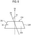
- a combination weighing apparatus 1 in a first variation is described below with reference to FIG. 6 , focusing on a difference from the combination weighing apparatus 1 according to the second embodiment that has been described above.
- the direction D3 in which the inclined faces 22 rise deviates from the circumferential direction D2 by a predetermined angle A1.
- the inclined faces 22 can be formed to correspond to an actual track along which the articles are conveyed on the dispersion table 10, and therefore adhesion of the articles can be further reduced, and conveyance performance can be improved.
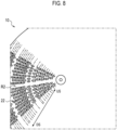
- a combination weighing apparatus 1 in a second variation is described below with reference to FIGS. 7 and 8 , focusing on a difference from the combination weighing apparatuses 1 according to the first and second embodiments that have been described above.
- a region R2 where the inclined faces 22 are not disposed may be provided along the radiation direction D1.
- a reinforcing member of the dispersion table 10 can be disposed on the reverse face 24 of the region R1 or the region R2 that has been described above.
- a combination weighing apparatus 1 in a third variation is described below with reference to FIG. 9 , focusing on a difference from the combination weighing apparatuses 1 according to the first and second embodiments that have been described above.
- the dispersion table 10 may have a shape in which a cone 10A having an acute vertex angle is coaxially superimposed onto a center of a cone 10B having an obtuse vertex angle.
- the diameter of the cone 10B is larger than the diameter of the cone 10A.
- the inclined faces 22 can avoid adhesion of the adhesive articles to the surface 10S the dispersion table 10.
- the conveyance force of the conveyors 11 to be applied to the articles can be improved due to the lower ends 22E of the inclined faces 22.
- the inclined faces 22 are disposed to correspond to a direction in which the conveyance force is applied (the circumferential direction D2 or the radiation direction D1), and therefore the conveyance force can be increased, and dispersiveness can be improved simultaneously.
- the plurality of inclined faces 22 is disposed along the radiation direction D1.
- the plurality of inclined faces 22 is disposed along the circumferential direction D2. Therefore, a conveyance ability in an intended direction can be improved.
- an inclination angle of the dispersion table 10 can be decreased, and this can solve a problem in which the height of the combination weighing apparatus 1 increases.
Landscapes
- Physics & Mathematics (AREA)
- General Physics & Mathematics (AREA)
- Engineering & Computer Science (AREA)
- Mechanical Engineering (AREA)
- Feeding Of Articles To Conveyors (AREA)
- Filling Or Emptying Of Bunkers, Hoppers, And Tanks (AREA)
Abstract
Description
- The present invention relates to a combination weighing apparatus.
- Conventionally, in order to disperse adhesive articles that are difficult to convey, such as raw chicken, onto a conveyor that is radially disposed, a dispersion table that is rotated by using a motor to convey the articles, and a dispersion table that conveys the articles by using vibration are known.
-
- Patent Document 1:
WO 2008/074354 A - Patent Document 2:
JP H07-006501 Y1 - Patent Document 3:
JP 2021-209156 A - However, the dispersion table that is rotated by using the motor to convey the articles has problems of a high cost, poor hygiene, and the like.
- Furthermore, the dispersion table that conveys the articles by using vibration has a problem in which the articles adhere, and therefore the conveyance force of the conveyor (a feeder) is not transmitted to the articles, and the articles fail to be conveyed. In order to solve such problems, in a case where an inclination angle of such a dispersion table is increased, a problem in which the articles roll down on the dispersion table in one direction immediately after feeding the articles, and this causes a deterioration in dispersiveness, or a problem in which the height of an apparatus increases, and layout is limited newly arises.
- Moreover, conventionally, as countermeasures against adhesion of the articles, or as an increase in conveyance force, it has been proposed that a serrated unevenness or groove is provided. However, there has been a problem in which it is difficult to apply this proposal to a dispersion table having a conical shape.
- Accordingly, the present invention has been made in view of the problems described above, and it is an object of the present invention to provide a combination weighing apparatus that is capable of appropriately conveying adhesive articles to a conveyor.
- A combination weighing device according to one embodiment is summarized as including a dispersion table that receives and conveys an article that has been supplied from an outside; a driving unit that applies conveyance force to the dispersion table, the conveyance force causing the article to be conveyed; a plurality of conveyors that receives the article from the dispersion table, and conveys the article toward a downstream side; a plurality of hoppers that temporarily receives a plurality of the articles that has been discharged from the plurality of conveyors, and discharges the plurality of the articles to the downstream side; an obtaining unit that obtains a weight value of the article that is retained in each of the plurality of hoppers; and a controller that performs combination calculation on a basis of the weight value that has been obtained by the obtaining unit, wherein on a surface on which the article is conveyed in the dispersion table, a plurality of inclined faces is disposed, the plurality of inclined faces rising along a circumferential direction or a radiation direction.
- According to an embodiment of the present invention, it is possible to provide a combination weighing apparatus that is capable of appropriately conveying adhesive articles to a conveyor.
-
-
FIG. 1 is a diagram explaining an example of the entire configuration of a combination weighing apparatus according to an embodiment; -
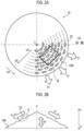
FIGS. 2A and 2B are diagrams for explaining an example of a dispersion table of the combination weighing apparatus according to the embodiment; -
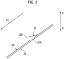
FIG. 3 is an enlarged view of a region A inFIG. 2B ; -
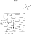
FIG. 4 is an enlarged view of a region B inFIG. 2A ; -
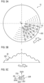
FIGS. 5A to 5C are diagrams for explaining an example of a dispersion table of a combination weighing apparatus according to an embodiment; -
FIG. 6 is a diagram for explaining an example of an inclined face that is disposed on a surface of a dispersion table of a combination weighing apparatus in a variation; -
FIG. 7 is a diagram for explaining an example of a dispersion table of a combination weighing apparatus in a variation; -
FIG. 8 is a diagram for explaining an example of the dispersion table of the combination weighing apparatus in the variation; and -
FIG. 9 is a diagram for explaining an example of a dispersion table of a combination weighing apparatus in a variation. - Hereinafter, the present embodiment will be described in detail with reference to the attached drawings. In the following description of the drawings, the same or similar parts are denoted by the same or similar reference symbols. However, note that the drawings are schematic, and ratios of dimensions are different from actual ones. Therefore, specific dimensions and the like are determined in consideration of the following description. Moreover, there may be portions where dimensional relationships or proportions are different among the drawings. In this specification and the drawings, elements having substantially the same function and configuration are denoted by the same reference numerals to omit redundant description, and elements not directly related to the present invention are omitted.
- A combination weighing apparatus 1 according to a first embodiment of the present invention is described below with reference to
FIGS. 1 to 4 . - As illustrated in
FIG. 1 , the combination weighing apparatus 1 according to the present embodiment includes a dispersion table 10, adriving unit 20, a plurality of conveyors 11, a plurality ofpool hoppers 12, a plurality of weighinghoppers 13, acollection discharge chute 15, an obtainingunit 30, and acontroller 31. - The dispersion table 10 receives articles (objects to be weighed) that have been supplied from an outside (a supply apparatus), and conveys the articles to the conveyors 11, while dispersing the articles.
- For example, as illustrated in
FIGS. 2A and 2B , vibration is applied in a vibration direction D4 of an upward/downward direction U/D by thedriving unit 20 described later, and therefore the dispersion table 10 according to the present embodiment conveys the articles toward a downstream side (an outside in a radial direction) DS, while dispersing the articles in a radiation direction D1. In this case, a configuration in which a combination of vibration in the vibration direction D4 described above and vibration in a circumferential direction D2 is applied to the articles may be employed. - Note that the dispersion table 10 is not limited to such a configuration, and may have a mechanism of being driven to rotate around a rotation axis C that extends in the upward/downward direction U/D to convey the articles to the conveyors 11. In other words, any configuration may be employed, if the dispersion table 10 has a function of conveying such articles to the conveyors 11.
- For example, such articles are soft and adhesive foods, such as raw chicken. However, the articles are not limited to these. Specific examples include fruit such as prune or cut pineapple, and candies coated with sugar, and any articles may be employed.
- The
driving unit 20 applies, to the dispersion table 10, conveyance force that causes the articles to be conveyed. In the present embodiment, as illustrated inFIGS. 2A and 2B , thedriving unit 20 is configured to apply vibration in the vibration direction D4 of the upward/downward direction U/D to the dispersion table 10. - Each of the conveyors 11 receives the articles from the dispersion table 10, and conveys the articles from an upstream side US toward the downstream side DS. In the present embodiment, each of the conveyors 11 is configured to supply the articles that have been supplied from the dispersion table 10, to the
pool hopper 12 that is provided to correspond to the downstream side DS of each of the conveyors 11. - Here, each of the conveyors 11 may include a vibration feeder of a type of conveying the articles by using vibration, or may include a screw feeder of a type of conveying the articles by rotating a screw that is provided in a trough.
- Each of the
pool hoppers 12 temporarily receives the article that has been discharged from the conveyor 11, and discharges the article to each of theweighing hoppers 13 that is disposed on the downstream side. - Each of the weighing
hoppers 13 temporarily retains the article that has been discharged by thepool hopper 12, and weighs a weight value of the article. Each of the weighinghoppers 13 discharges the temporarily retained article to thecollection discharge chute 15 that is disposed on the downstream side. - The obtaining
unit 30 obtains the weight value of the article that has been retained by each of the weighinghoppers 13. Thecontroller 31 performs combination calculation on the basis of the weight values of the articles that have been obtained by the obtainingunit 30. - The
collection discharge chute 15 collects the articles that have been discharged from the plurality of weighinghoppers 13, and drops the articles downward. - An example of the dispersion table 10 of the combination weighing apparatus 1 according to the present embodiment is described below with reference to
FIGS. 2 and3 . - As illustrated in
FIGS. 2A and 2B , the dispersion table 10 includes a plurality of inclined faces (protrusions) 22 on asurface 10S on which the articles are conveyed. Stated another way, slatted-shutter working has been performed on thesurface 10S on which the articles are conveyed in the dispersion table 10. Slatted-shutter working may be louver working. - In the present embodiment, as illustrated in
FIGS. 2A and 2B , the plurality of inclined faces 22 is disposed on thesurface 10S on which the articles are conveyed in the dispersion table 10. - Here, as illustrated in
FIG. 3 , the plurality of inclined faces 22 rises along the radiation direction D1. Note that, as illustrated inFIG. 2A , the radiation direction D1 is a direction that is orthogonal to the circumferential direction D2, and goes from the upstream side US to the downstream side DS. - As illustrated in
FIG. 3 , the respective inclined faces 22 include a plurality ofprotrusions 22 that is provided on thesurface 10S on which the articles are conveyed. Furthermore, as illustrated inFIG. 3 , at lower ends 22E in the radiation direction D1 of the plurality ofprotrusions 22, anopening 21A that faces areverse face 24 from thesurface 10S is disposed. - In other words, as illustrated in
FIGS. 3 and4 , the dispersion table 10 includes a first sliding face (the surface) 10S that includes a plurality ofopenings 21A, and a second sliding face (the inclined face or the protrusion) 22 that closes part of each of the plurality ofopenings 21A, and is disposed in a position on an upper side U of the dispersion table 10 relative to the first slidingface 10S. - The second sliding
face 22 is formed to be continuous to the first slidingface 10S on the upstream side US, a left-hand side L, and a right-hand side R of theopening 21A described above. - Specifically, as illustrated in
FIG. 4 , the second slidingface 22 includes a left-hand sideflat face 22L, a right-hand sideflat face 22R, and an upper sideflat face 22U. - Here, the left-hand side
flat face 22L is formed to rise from the first slidingface 10S toward the upper side U on the left-hand side L of theopening 21A, as illustrated inFIG. 4 . - Furthermore, the right-hand side
flat face 22R is formed to rise from the first slidingface 10S toward the upper side U on the right-hand side R of theopening 21A, as illustrated inFIG. 4 . - Moreover, the upper side
flat face 22U is formed to couple the left-hand sideflat face 22L to the right-hand sideflat face 22R, as illustrated inFIG. 4 . - On the
surface 10S on which the articles are conveyed in the dispersion table 10, as described above, the articles slide from the upstream side US to the downstream side DS along the first slidingface 10S and the upper side flat faces 22U of the second sliding faces 22 due to driving force from the drivingunit 20, or the like, as illustrated inFIGS. 2 and4 . - By employing such a configuration, the inclined faces (the protrusions or the second sliding faces) 22 are provided on the
surface 10S on which the article is conveyed in the dispersion table 10. Therefore, an area of contact between the article having high adhesiveness and thesurface 10S can be decreased, adhesion of the article to thesurface 10S can be reduced, and conveyance control can be appropriately performed. - Moreover, even in a case where the article having high adhesiveness has come into contact with the
surface 10S, air flows from theopenings 21A. Therefore, an air layer can be formed between thesurface 10S and the article, and air pressure is also applied to a portion where thesurface 10S is in contact with the article. This can reduce adhesion of the article to thesurface 10S. - Note that a configuration in which the
openings 21A are formed has been described above. However, this configuration is not restrictive, and a configuration in which theopenings 21A are absent may be employed. - Furthermore, a movement of the article to the upstream side US is regulated by the
lower end 22E, and therefore the article is smoothly conveyed to the downstream side DS. - A combination weighing apparatus 1 according to a second embodiment is described below with reference to
FIG. 5 , focusing on a difference from the combination weighing apparatus 1 according to the first embodiment that has been described above. - In the present second embodiment, as illustrated in
FIG. 5A , the dispersion table 10 is driven to rotate around the rotation axis C that extends in the upward/downward direction U/D to convey the articles toward the conveyors 11. - Here, in the present second embodiment, as illustrated in
FIGS. 5A and 5B , a plurality of inclined faces 22 that rises along the circumferential direction D2 is disposed on thesurface 10S on which the articles are conveyed in the dispersion table 10. - Stated another way, in the present second embodiment, as illustrated in
FIG. 5C , in a plan view, a direction D3 in which the inclined faces 22 rise matches the circumferential direction D2. Note that, as illustrated inFIG. 5C , in a plan view, the upper sideflat face 22U has a trapezoidal shape, and the direction D3 in which the inclined faces 22 rise and the circumferential direction D2 are orthogonal to an upper side 22U1 and a lower side 22U2 in the upper sideflat face 22U. - A combination weighing apparatus 1 in a first variation is described below with reference to
FIG. 6 , focusing on a difference from the combination weighing apparatus 1 according to the second embodiment that has been described above. - As illustrated in
FIG. 6 , in the present first variation, the direction D3 in which the inclined faces 22 rise deviates from the circumferential direction D2 by a predetermined angle A1. - By employing such a configuration, the inclined faces 22 can be formed to correspond to an actual track along which the articles are conveyed on the dispersion table 10, and therefore adhesion of the articles can be further reduced, and conveyance performance can be improved.
- A combination weighing apparatus 1 in a second variation is described below with reference to
FIGS. 7 and8 , focusing on a difference from the combination weighing apparatuses 1 according to the first and second embodiments that have been described above. - As illustrated in
FIG. 7 , in the present second variation, a region R1 where the inclined faces 22 are not disposed may be provided along the circumferential direction D2. - Alternatively, as illustrated in
FIG. 8 , in the present second variation, a region R2 where the inclined faces 22 are not disposed may be provided along the radiation direction D1. - By employing such a configuration, welding can be performed in the region R1 or the region R2 that has been described above. Alternatively, a reinforcing member of the dispersion table 10 can be disposed on the
reverse face 24 of the region R1 or the region R2 that has been described above. - A combination weighing apparatus 1 in a third variation is described below with reference to
FIG. 9 , focusing on a difference from the combination weighing apparatuses 1 according to the first and second embodiments that have been described above. - As illustrated in
FIG. 9 , in the third variation, the dispersion table 10 may have a shape in which acone 10A having an acute vertex angle is coaxially superimposed onto a center of acone 10B having an obtuse vertex angle. The diameter of thecone 10B is larger than the diameter of thecone 10A. - By employing the combination weighing apparatus 1 described above, the inclined faces 22 can avoid adhesion of the adhesive articles to the
surface 10S the dispersion table 10. - Furthermore, by employing the combination weighing apparatus 1 described above, the conveyance force of the conveyors 11 to be applied to the articles can be improved due to the lower ends 22E of the inclined faces 22.
- Furthermore, by employing the combination weighing apparatus 1 described above, the inclined faces 22 are disposed to correspond to a direction in which the conveyance force is applied (the circumferential direction D2 or the radiation direction D1), and therefore the conveyance force can be increased, and dispersiveness can be improved simultaneously. For example, in the case of the dispersion table 10 that conveys the articles by using vibration, the plurality of inclined faces 22 is disposed along the radiation direction D1. In the case of the dispersion table 10 that is rotated by using a motor to convey the articles, the plurality of inclined faces 22 is disposed along the circumferential direction D2. Therefore, a conveyance ability in an intended direction can be improved.
- Moreover, by employing the combination weighing apparatus 1 described above, an inclination angle of the dispersion table 10 can be decreased, and this can solve a problem in which the height of the combination weighing apparatus 1 increases.
- Although the present invention is explained in detail using the above-mentioned embodiments, it will be apparent to those skilled in the art that the present invention is not limited to the embodiments described herein. The present invention can be implemented as modifications and changes without departing from the spirit and scope of the present invention defined by the description of the claims. Accordingly, the description of the present specification is for the purpose of illustration and is not intended to limit the present invention in any way.
-
- 1
- Combination weighing apparatus
- 10
- Dispersion table
- 10S
- Surface
- 11
- Conveyor
- 12
- Pool hopper
- 12a
- Gate
- 13
- Weighing hopper
- 15
- Collection discharge chute
- 20
- Driving unit
- 21A
- Opening
- 22
- Inclined face, Protrusions
- 22E
- Lower end
- 24
- Reverse face
- 30
- Obtaining unit
- 31
- Controller
- A1
- Predetermined angle
- D1
- Radiation direction
- D2
- Circumferential direction
- D3
- Direction in which Inclined faces rise
- D4
- Vibration direction
- R1
- Region where Inclined faces are not disposed
Claims (6)
- A combination weighing apparatus comprising:a dispersion table that receives and conveys an article that has been supplied from an outside;a driving unit that applies conveyance force to the dispersion table, the conveyance force causing the article to be conveyed;a plurality of conveyors that receives the article from the dispersion table, and conveys the article toward a downstream side;a plurality of hoppers that temporarily receives a plurality of the articles that has been discharged from the plurality of conveyors, and discharges the plurality of the articles to the downstream side;an obtaining unit that obtains a weight value of the article that is retained in each of the plurality of hoppers; anda controller that performs combination calculation on a basis of the weight value that has been obtained by the obtaining unit, whereinon a surface on which the article is conveyed in the dispersion table, a plurality of inclined faces is disposed, the plurality of inclined faces rising along a circumferential direction or a radiation direction.
- The combination weighing apparatus according to claim 1, whereinthe plurality of inclined faces includes a plurality of protrusions that is provided on the surface on which the article is conveyed, andat lower ends in the circumferential direction or the radiation direction of the plurality of protrusions, an opening that faces a reverse face from the surface is disposed.
- The combination weighing apparatus according to claim 1 or 2, wherein
in a plan view, a direction in which the plurality of inclined faces rises deviates from the circumferential direction by a predetermined angle. - The combination weighing apparatus according to claim 1 or 2, wherein
the radiation direction is a direction that is orthogonal to the circumferential direction, and goes from an upstream side to the downstream side. - The combination weighing apparatus according to any one of claims 1 to 5, wherein
a region where the plurality of inclined faces is not disposed is provided along the circumferential direction. - The combination weighing apparatus according to any one of claims 1 to 5, wherein
a region where the plurality of inclined faces is not disposed is provided along the radiation direction.
Applications Claiming Priority (1)
| Application Number | Priority Date | Filing Date | Title |
|---|---|---|---|
| JP2022043747A JP2023137505A (en) | 2022-03-18 | 2022-03-18 | Combination register |
Publications (2)
| Publication Number | Publication Date |
|---|---|
| EP4246105A1 true EP4246105A1 (en) | 2023-09-20 |
| EP4246105B1 EP4246105B1 (en) | 2025-06-25 |
Family
ID=85703624
Family Applications (1)
| Application Number | Title | Priority Date | Filing Date |
|---|---|---|---|
| EP23161985.9A Active EP4246105B1 (en) | 2022-03-18 | 2023-03-15 | Combination weighing apparatus |
Country Status (5)
| Country | Link |
|---|---|
| US (1) | US12480803B2 (en) |
| EP (1) | EP4246105B1 (en) |
| JP (1) | JP2023137505A (en) |
| CN (1) | CN116767817B (en) |
| DK (1) | DK4246105T3 (en) |
Cited By (1)
| Publication number | Priority date | Publication date | Assignee | Title |
|---|---|---|---|---|
| EP4700341A1 (en) * | 2024-08-23 | 2026-02-25 | Ishida Co., Ltd. | Distributing and feeding apparatus and combination weighing apparatus |
Families Citing this family (1)
| Publication number | Priority date | Publication date | Assignee | Title |
|---|---|---|---|---|
| JP7315955B2 (en) * | 2019-08-09 | 2023-07-27 | 株式会社イシダ | Combination weighing device |
Citations (3)
| Publication number | Priority date | Publication date | Assignee | Title |
|---|---|---|---|---|
| JPH076501Y2 (en) | 1989-04-12 | 1995-02-15 | 大和製衡株式会社 | Feeder for combination scales |
| WO2008074354A1 (en) | 2006-12-21 | 2008-06-26 | MULTIPOND Wägetechnik GmbH | Product transport surface comprising grooves |
| JP2010281748A (en) * | 2009-06-05 | 2010-12-16 | Ishida Co Ltd | Combination weighing device and electromagnetic feeder |
Family Cites Families (22)
| Publication number | Priority date | Publication date | Assignee | Title |
|---|---|---|---|---|
| GB2074329B (en) * | 1980-03-25 | 1984-05-16 | Ishida Scale Mfg Co Ltd | Automatic weighing apparatus |
| JPS586233U (en) * | 1981-07-07 | 1983-01-14 | 株式会社石田衡器製作所 | Distributed supply device |
| AU543930B2 (en) | 1981-07-07 | 1985-05-09 | K.K. Ishida Koki Seisakusho | Dispensing feeder |
| JPS5841324A (en) * | 1981-09-04 | 1983-03-10 | Ishida Scales Mfg Co Ltd | Automatic measuring apparatus |
| JPS5946820A (en) * | 1982-09-11 | 1984-03-16 | Ishida Scales Mfg Co Ltd | Combination weighing method |
| JPS59144532U (en) * | 1983-03-16 | 1984-09-27 | 大和製衡株式会社 | Dispersion feeder for combination weighers |
| US4576209A (en) * | 1985-02-06 | 1986-03-18 | Solbern Corp. | Method and apparatus for delivering a predetermined amount of material to a container |
| DE3687147T2 (en) * | 1985-12-29 | 1993-04-22 | Anritsu Corp | COMBINATIONAL WEIGHING APPARATUS. |
| US4678046A (en) * | 1986-01-31 | 1987-07-07 | Package Machinery Company | Combination weighing apparatus for two combined products |
| SE463296B (en) * | 1987-11-11 | 1990-11-05 | Inst Verkstadstek Forsk Ivf | SETTING AND DEVICE TO TRANSPORT AND DISPOSABLE ADJUSTABLE MATERIALS |
| JPH08145769A (en) * | 1994-11-21 | 1996-06-07 | Ishida Co Ltd | Distributing and supplying device for objects to be weighed in combination weighing device |
| JP2001050803A (en) * | 1999-08-06 | 2001-02-23 | Ishida Co Ltd | Combination weighing device |
| JP2006199424A (en) * | 2005-01-20 | 2006-08-03 | Ishida Co Ltd | Conveying device and combination weighing device provided with the same |
| JP2011209156A (en) | 2010-03-30 | 2011-10-20 | Ishida Co Ltd | Combination weighing device |
| WO2014067533A1 (en) * | 2012-11-02 | 2014-05-08 | Marel A/S | An anti-sticking surface plate structure to be used as a low-friction based material in a food processing apparatus and method for its manufacture |
| EP3101398B1 (en) * | 2014-01-30 | 2020-10-14 | Ishida Co., Ltd. | Combination weighing apparatus |
| EP3196609B1 (en) * | 2014-09-19 | 2021-09-15 | Ishida Co., Ltd. | Dispersion and supply device and combination weighing device |
| JP6454185B2 (en) * | 2015-03-10 | 2019-01-16 | 株式会社イシダ | Combination weighing device |
| JP6711264B2 (en) * | 2016-12-27 | 2020-06-17 | 三菱自動車工業株式会社 | scrap shooting |
| CN208278362U (en) * | 2018-04-03 | 2018-12-25 | 高州市丰盛食品有限公司 | A kind of pulp automatic weighing and packing machine |
| JP7315955B2 (en) * | 2019-08-09 | 2023-07-27 | 株式会社イシダ | Combination weighing device |
| JP2021143970A (en) * | 2020-03-13 | 2021-09-24 | 株式会社イシダ | Conveyance mechanism and combination weighing machine |
-
2022
- 2022-03-18 JP JP2022043747A patent/JP2023137505A/en active Pending
-
2023
- 2023-03-10 CN CN202310246680.4A patent/CN116767817B/en active Active
- 2023-03-10 US US18/181,882 patent/US12480803B2/en active Active
- 2023-03-15 EP EP23161985.9A patent/EP4246105B1/en active Active
- 2023-03-15 DK DK23161985.9T patent/DK4246105T3/en active
Patent Citations (3)
| Publication number | Priority date | Publication date | Assignee | Title |
|---|---|---|---|---|
| JPH076501Y2 (en) | 1989-04-12 | 1995-02-15 | 大和製衡株式会社 | Feeder for combination scales |
| WO2008074354A1 (en) | 2006-12-21 | 2008-06-26 | MULTIPOND Wägetechnik GmbH | Product transport surface comprising grooves |
| JP2010281748A (en) * | 2009-06-05 | 2010-12-16 | Ishida Co Ltd | Combination weighing device and electromagnetic feeder |
Cited By (1)
| Publication number | Priority date | Publication date | Assignee | Title |
|---|---|---|---|---|
| EP4700341A1 (en) * | 2024-08-23 | 2026-02-25 | Ishida Co., Ltd. | Distributing and feeding apparatus and combination weighing apparatus |
Also Published As
| Publication number | Publication date |
|---|---|
| DK4246105T3 (en) | 2025-07-21 |
| EP4246105B1 (en) | 2025-06-25 |
| CN116767817B (en) | 2026-03-17 |
| US20230296423A1 (en) | 2023-09-21 |
| JP2023137505A (en) | 2023-09-29 |
| CN116767817A (en) | 2023-09-19 |
| US12480803B2 (en) | 2025-11-25 |
Similar Documents
| Publication | Publication Date | Title |
|---|---|---|
| EP4246105B1 (en) | Combination weighing apparatus | |
| CN1117687C (en) | device for controlling the flow of goods | |
| EP0992860A3 (en) | Image forming apparatus | |
| US8770381B2 (en) | Bread conveying apparatus and bread packaging system | |
| JP2003226419A (en) | Parts feeder | |
| US11927470B2 (en) | Combination weighing apparatus with discharge chute including slide surface | |
| JP2017047976A (en) | Method of controlling belt conveyer system | |
| EP2772458A1 (en) | Rotary pipe-type linear feeder | |
| US20170043956A1 (en) | Sheet stacking apparatus having adjustable length conveyor section | |
| US20210284463A1 (en) | Conveyance mechanism and combination weighing apparatus | |
| EP4140918B1 (en) | Conveyance apparatus | |
| US7121397B2 (en) | Medicine package conveying apparatus | |
| US7753357B2 (en) | Stacking apparatus having tiltable main conveyor and variable length transfer conveyor | |
| US20100297278A1 (en) | Strand pelletizer | |
| CN210972927U (en) | Drive plate transmission device | |
| JP2018157796A (en) | Food forming equipment | |
| JP2005200215A (en) | Feeder for article such as fruit | |
| JP2006199424A (en) | Conveying device and combination weighing device provided with the same | |
| KR102763862B1 (en) | Fruit Sorting Apparatus Equipped with Screw-type Feeder | |
| JP7597356B2 (en) | Item transport device | |
| EP1538114B1 (en) | Feeding apparatus for products such as fruits | |
| US12631480B2 (en) | Weighing apparatus | |
| CN209956845U (en) | Automatic feeding machine based on transmission mechanism | |
| US20240280398A1 (en) | Weighing apparatus | |
| EP4589268A1 (en) | Combination weighing apparatus |
Legal Events
| Date | Code | Title | Description |
|---|---|---|---|
| PUAI | Public reference made under article 153(3) epc to a published international application that has entered the european phase |
Free format text: ORIGINAL CODE: 0009012 |
|
| STAA | Information on the status of an ep patent application or granted ep patent |
Free format text: STATUS: REQUEST FOR EXAMINATION WAS MADE |
|
| 17P | Request for examination filed |
Effective date: 20230315 |
|
| AK | Designated contracting states |
Kind code of ref document: A1 Designated state(s): AL AT BE BG CH CY CZ DE DK EE ES FI FR GB GR HR HU IE IS IT LI LT LU LV MC ME MK MT NL NO PL PT RO RS SE SI SK SM TR |
|
| GRAP | Despatch of communication of intention to grant a patent |
Free format text: ORIGINAL CODE: EPIDOSNIGR1 |
|
| STAA | Information on the status of an ep patent application or granted ep patent |
Free format text: STATUS: GRANT OF PATENT IS INTENDED |
|
| INTG | Intention to grant announced |
Effective date: 20250122 |
|
| RIN1 | Information on inventor provided before grant (corrected) |
Inventor name: KASUGAI, TAKAHIDE Inventor name: KISHIKAWA, MIKIO Inventor name: ICHIHASHI, RYO |
|
| GRAS | Grant fee paid |
Free format text: ORIGINAL CODE: EPIDOSNIGR3 |
|
| GRAA | (expected) grant |
Free format text: ORIGINAL CODE: 0009210 |
|
| STAA | Information on the status of an ep patent application or granted ep patent |
Free format text: STATUS: THE PATENT HAS BEEN GRANTED |
|
| AK | Designated contracting states |
Kind code of ref document: B1 Designated state(s): AL AT BE BG CH CY CZ DE DK EE ES FI FR GB GR HR HU IE IS IT LI LT LU LV MC ME MK MT NL NO PL PT RO RS SE SI SK SM TR |
|
| REG | Reference to a national code |
Ref country code: GB Ref legal event code: FG4D |
|
| REG | Reference to a national code |
Ref country code: CH Ref legal event code: EP |
|
| REG | Reference to a national code |
Ref country code: CH Ref legal event code: EP |
|
| REG | Reference to a national code |
Ref country code: IE Ref legal event code: FG4D |
|
| REG | Reference to a national code |
Ref country code: DE Ref legal event code: R096 Ref document number: 602023004183 Country of ref document: DE |
|
| REG | Reference to a national code |
Ref country code: DK Ref legal event code: T3 Effective date: 20250715 |
|
| PG25 | Lapsed in a contracting state [announced via postgrant information from national office to epo] |
Ref country code: FI Free format text: LAPSE BECAUSE OF FAILURE TO SUBMIT A TRANSLATION OF THE DESCRIPTION OR TO PAY THE FEE WITHIN THE PRESCRIBED TIME-LIMIT Effective date: 20250625 |
|
| REG | Reference to a national code |
Ref country code: LT Ref legal event code: MG9D |
|
| PG25 | Lapsed in a contracting state [announced via postgrant information from national office to epo] |
Ref country code: NO Free format text: LAPSE BECAUSE OF FAILURE TO SUBMIT A TRANSLATION OF THE DESCRIPTION OR TO PAY THE FEE WITHIN THE PRESCRIBED TIME-LIMIT Effective date: 20250925 Ref country code: GR Free format text: LAPSE BECAUSE OF FAILURE TO SUBMIT A TRANSLATION OF THE DESCRIPTION OR TO PAY THE FEE WITHIN THE PRESCRIBED TIME-LIMIT Effective date: 20250926 |
|
| PG25 | Lapsed in a contracting state [announced via postgrant information from national office to epo] |
Ref country code: BG Free format text: LAPSE BECAUSE OF FAILURE TO SUBMIT A TRANSLATION OF THE DESCRIPTION OR TO PAY THE FEE WITHIN THE PRESCRIBED TIME-LIMIT Effective date: 20250625 |
|
| PG25 | Lapsed in a contracting state [announced via postgrant information from national office to epo] |
Ref country code: HR Free format text: LAPSE BECAUSE OF FAILURE TO SUBMIT A TRANSLATION OF THE DESCRIPTION OR TO PAY THE FEE WITHIN THE PRESCRIBED TIME-LIMIT Effective date: 20250625 |
|
| PG25 | Lapsed in a contracting state [announced via postgrant information from national office to epo] |
Ref country code: RS Free format text: LAPSE BECAUSE OF FAILURE TO SUBMIT A TRANSLATION OF THE DESCRIPTION OR TO PAY THE FEE WITHIN THE PRESCRIBED TIME-LIMIT Effective date: 20250925 |
|
| PG25 | Lapsed in a contracting state [announced via postgrant information from national office to epo] |
Ref country code: LV Free format text: LAPSE BECAUSE OF FAILURE TO SUBMIT A TRANSLATION OF THE DESCRIPTION OR TO PAY THE FEE WITHIN THE PRESCRIBED TIME-LIMIT Effective date: 20250625 |
|
| REG | Reference to a national code |
Ref country code: NL Ref legal event code: MP Effective date: 20250625 |
|
| PG25 | Lapsed in a contracting state [announced via postgrant information from national office to epo] |
Ref country code: NL Free format text: LAPSE BECAUSE OF FAILURE TO SUBMIT A TRANSLATION OF THE DESCRIPTION OR TO PAY THE FEE WITHIN THE PRESCRIBED TIME-LIMIT Effective date: 20250625 |
|
| PG25 | Lapsed in a contracting state [announced via postgrant information from national office to epo] |
Ref country code: PT Free format text: LAPSE BECAUSE OF FAILURE TO SUBMIT A TRANSLATION OF THE DESCRIPTION OR TO PAY THE FEE WITHIN THE PRESCRIBED TIME-LIMIT Effective date: 20251027 |
|
| REG | Reference to a national code |
Ref country code: AT Ref legal event code: MK05 Ref document number: 1806860 Country of ref document: AT Kind code of ref document: T Effective date: 20250625 |
|
| PG25 | Lapsed in a contracting state [announced via postgrant information from national office to epo] |
Ref country code: IS Free format text: LAPSE BECAUSE OF FAILURE TO SUBMIT A TRANSLATION OF THE DESCRIPTION OR TO PAY THE FEE WITHIN THE PRESCRIBED TIME-LIMIT Effective date: 20251025 |
|
| PG25 | Lapsed in a contracting state [announced via postgrant information from national office to epo] |
Ref country code: AT Free format text: LAPSE BECAUSE OF FAILURE TO SUBMIT A TRANSLATION OF THE DESCRIPTION OR TO PAY THE FEE WITHIN THE PRESCRIBED TIME-LIMIT Effective date: 20250625 Ref country code: SM Free format text: LAPSE BECAUSE OF FAILURE TO SUBMIT A TRANSLATION OF THE DESCRIPTION OR TO PAY THE FEE WITHIN THE PRESCRIBED TIME-LIMIT Effective date: 20250625 |
|
| PG25 | Lapsed in a contracting state [announced via postgrant information from national office to epo] |
Ref country code: CZ Free format text: LAPSE BECAUSE OF FAILURE TO SUBMIT A TRANSLATION OF THE DESCRIPTION OR TO PAY THE FEE WITHIN THE PRESCRIBED TIME-LIMIT Effective date: 20250625 |
|
| PG25 | Lapsed in a contracting state [announced via postgrant information from national office to epo] |
Ref country code: PL Free format text: LAPSE BECAUSE OF FAILURE TO SUBMIT A TRANSLATION OF THE DESCRIPTION OR TO PAY THE FEE WITHIN THE PRESCRIBED TIME-LIMIT Effective date: 20250625 |
|
| PG25 | Lapsed in a contracting state [announced via postgrant information from national office to epo] |
Ref country code: EE Free format text: LAPSE BECAUSE OF FAILURE TO SUBMIT A TRANSLATION OF THE DESCRIPTION OR TO PAY THE FEE WITHIN THE PRESCRIBED TIME-LIMIT Effective date: 20250625 |
|
| PG25 | Lapsed in a contracting state [announced via postgrant information from national office to epo] |
Ref country code: SK Free format text: LAPSE BECAUSE OF FAILURE TO SUBMIT A TRANSLATION OF THE DESCRIPTION OR TO PAY THE FEE WITHIN THE PRESCRIBED TIME-LIMIT Effective date: 20250625 |
|
| PG25 | Lapsed in a contracting state [announced via postgrant information from national office to epo] |
Ref country code: ES Free format text: LAPSE BECAUSE OF FAILURE TO SUBMIT A TRANSLATION OF THE DESCRIPTION OR TO PAY THE FEE WITHIN THE PRESCRIBED TIME-LIMIT Effective date: 20250625 |
|
| PGFP | Annual fee paid to national office [announced via postgrant information from national office to epo] |
Ref country code: DK Payment date: 20260323 Year of fee payment: 4 Ref country code: DE Payment date: 20260320 Year of fee payment: 4 |
|
| PG25 | Lapsed in a contracting state [announced via postgrant information from national office to epo] |
Ref country code: IT Free format text: LAPSE BECAUSE OF FAILURE TO SUBMIT A TRANSLATION OF THE DESCRIPTION OR TO PAY THE FEE WITHIN THE PRESCRIBED TIME-LIMIT Effective date: 20250625 |
|
| PLBE | No opposition filed within time limit |
Free format text: ORIGINAL CODE: 0009261 |
|
| STAA | Information on the status of an ep patent application or granted ep patent |
Free format text: STATUS: NO OPPOSITION FILED WITHIN TIME LIMIT |
|
| REG | Reference to a national code |
Ref country code: CH Ref legal event code: L10 Free format text: ST27 STATUS EVENT CODE: U-0-0-L10-L00 (AS PROVIDED BY THE NATIONAL OFFICE) Effective date: 20260507 |