EP4246085A1 - Displacement measurement device, non-contact input apparatus, and biological micromotion measurement apparatus - Google Patents
Displacement measurement device, non-contact input apparatus, and biological micromotion measurement apparatus Download PDFInfo
- Publication number
- EP4246085A1 EP4246085A1 EP23158278.4A EP23158278A EP4246085A1 EP 4246085 A1 EP4246085 A1 EP 4246085A1 EP 23158278 A EP23158278 A EP 23158278A EP 4246085 A1 EP4246085 A1 EP 4246085A1
- Authority
- EP
- European Patent Office
- Prior art keywords
- luminance
- displacement
- change coordinate
- numerical
- change
- Prior art date
- Legal status (The legal status is an assumption and is not a legal conclusion. Google has not performed a legal analysis and makes no representation as to the accuracy of the status listed.)
- Pending
Links
Images








Classifications
-
- G—PHYSICS
- G01—MEASURING; TESTING
- G01B—MEASURING LENGTH, THICKNESS OR SIMILAR LINEAR DIMENSIONS; MEASURING ANGLES; MEASURING AREAS; MEASURING IRREGULARITIES OF SURFACES OR CONTOURS
- G01B11/00—Measuring arrangements characterised by the use of optical techniques
- G01B11/16—Measuring arrangements characterised by the use of optical techniques for measuring the deformation in a solid, e.g. optical strain gauge
- G01B11/161—Measuring arrangements characterised by the use of optical techniques for measuring the deformation in a solid, e.g. optical strain gauge by interferometric means
- G01B11/162—Measuring arrangements characterised by the use of optical techniques for measuring the deformation in a solid, e.g. optical strain gauge by interferometric means by speckle- or shearing interferometry
-
- G—PHYSICS
- G01—MEASURING; TESTING
- G01B—MEASURING LENGTH, THICKNESS OR SIMILAR LINEAR DIMENSIONS; MEASURING ANGLES; MEASURING AREAS; MEASURING IRREGULARITIES OF SURFACES OR CONTOURS
- G01B11/00—Measuring arrangements characterised by the use of optical techniques
- G01B11/002—Measuring arrangements characterised by the use of optical techniques for measuring two or more coordinates
-
- G—PHYSICS
- G01—MEASURING; TESTING
- G01B—MEASURING LENGTH, THICKNESS OR SIMILAR LINEAR DIMENSIONS; MEASURING ANGLES; MEASURING AREAS; MEASURING IRREGULARITIES OF SURFACES OR CONTOURS
- G01B11/00—Measuring arrangements characterised by the use of optical techniques
- G01B11/02—Measuring arrangements characterised by the use of optical techniques for measuring length, width or thickness
- G01B11/026—Measuring arrangements characterised by the use of optical techniques for measuring length, width or thickness by measuring distance between sensor and object
-
- G—PHYSICS
- G01—MEASURING; TESTING
- G01B—MEASURING LENGTH, THICKNESS OR SIMILAR LINEAR DIMENSIONS; MEASURING ANGLES; MEASURING AREAS; MEASURING IRREGULARITIES OF SURFACES OR CONTOURS
- G01B11/00—Measuring arrangements characterised by the use of optical techniques
- G01B11/14—Measuring arrangements characterised by the use of optical techniques for measuring distance or clearance between spaced objects or spaced apertures
-
- G—PHYSICS
- G01—MEASURING; TESTING
- G01S—RADIO DIRECTION-FINDING; RADIO NAVIGATION; DETERMINING DISTANCE OR VELOCITY BY USE OF RADIO WAVES; LOCATING OR PRESENCE-DETECTING BY USE OF THE REFLECTION OR RERADIATION OF RADIO WAVES; ANALOGOUS ARRANGEMENTS USING OTHER WAVES
- G01S17/00—Systems using the reflection or reradiation of electromagnetic waves other than radio waves, e.g. lidar systems
- G01S17/02—Systems using the reflection of electromagnetic waves other than radio waves
- G01S17/50—Systems of measurement based on relative movement of target
- G01S17/58—Velocity or trajectory determination systems; Sense-of-movement determination systems
-
- G—PHYSICS
- G06—COMPUTING OR CALCULATING; COUNTING
- G06V—IMAGE OR VIDEO RECOGNITION OR UNDERSTANDING
- G06V10/00—Arrangements for image or video recognition or understanding
- G06V10/40—Extraction of image or video features
- G06V10/62—Extraction of image or video features relating to a temporal dimension, e.g. time-based feature extraction; Pattern tracking
-
- G—PHYSICS
- G06—COMPUTING OR CALCULATING; COUNTING
- G06V—IMAGE OR VIDEO RECOGNITION OR UNDERSTANDING
- G06V20/00—Scenes; Scene-specific elements
- G06V20/60—Type of objects
- G06V20/69—Microscopic objects, e.g. biological cells or cellular parts
-
- G—PHYSICS
- G06—COMPUTING OR CALCULATING; COUNTING
- G06V—IMAGE OR VIDEO RECOGNITION OR UNDERSTANDING
- G06V40/00—Recognition of biometric, human-related or animal-related patterns in image or video data
- G06V40/20—Movements or behaviour, e.g. gesture recognition
-
- G—PHYSICS
- G06—COMPUTING OR CALCULATING; COUNTING
- G06V—IMAGE OR VIDEO RECOGNITION OR UNDERSTANDING
- G06V40/00—Recognition of biometric, human-related or animal-related patterns in image or video data
- G06V40/20—Movements or behaviour, e.g. gesture recognition
- G06V40/28—Recognition of hand or arm movements, e.g. recognition of deaf sign language
-
- H—ELECTRICITY
- H04—ELECTRIC COMMUNICATION TECHNIQUE
- H04N—PICTORIAL COMMUNICATION, e.g. TELEVISION
- H04N23/00—Cameras or camera modules comprising electronic image sensors; Control thereof
- H04N23/70—Circuitry for compensating brightness variation in the scene
- H04N23/71—Circuitry for evaluating the brightness variation
Definitions
- the present disclosure relates to a displacement measurement device, a non-contact input apparatus, and a biological micromotion measurement apparatus.
- a technique for measuring the amount of micro-displacement of a measurement object is disclosed in Zhou Ge., Yizhao Gao., Hayden K.-h. So., and Edmund Y Lam., "Event-based laser speckle correlation for micro motion estimation", Optics Letters, volume 46, no. 16/15, August 2021, pp. 3885 to 3888 .
- speckle patterns are acquired using an event-based vision sensor to generate speckle pattern images, and image processing is performed on the speckle pattern images to measure the amount of micro-displacement of the measurement object.
- event information output from photodetectors in an asynchronous manner is accumulated for a certain amount of time and is converted into images, and existing image processing is applied to the images to calculate the amounts of translation of the speckle pattern images.
- Such a technique involves a relatively large amount of computation in spite of the use of an event-based vision sensor, and the amount of displacement of the measurement object is difficult to detect at a high speed.
- a displacement measurement device includes an irradiation unit, a luminance-change coordinate point detection unit, and a displacement estimation unit.
- the irradiation unit irradiates a measurement object with coherent light.
- the luminance-change coordinate point detection unit detects a luminance-change coordinate point where a luminance change has occurred, based on light reflected from the measurement object, and outputs data related to the luminance-change coordinate point.
- the displacement estimation unit estimates an amount of displacement of the measurement object, based on the data related to the luminance-change coordinate point.
- the displacement estimation unit includes a first numerical-sequence processing system and a second numerical-sequence processing system.
- the first numerical-sequence processing system performs computation of a first numerical sequence including a set of first elements each representing a location of the luminance-change coordinate point extracted from the data to calculate the amount of displacement of the measurement object along the first elements.
- the second numerical-sequence processing system performs computation of a second numerical sequence including a set of second elements each representing a location of the luminance-change coordinate point extracted from the data to calculate the amount of displacement of the measurement object along the second elements.
- a non-contact input apparatus includes the displacement measurement device and a non-contact input identification unit that detects a non-contact operation based on information indicating the amount of displacement output from the displacement measurement device.
- a biological micromotion measurement apparatus includes the displacement measurement device and an optical system that receives reflected light from the measurement object.
- the reflected light results from light emitted from the displacement measurement device.
- the measurement object includes a living organism.
- the displacement measurement device detects an amount of micro-displacement of the measurement object by using the reflected light.
- At least one embodiment provides a displacement measurement device that can detect the amount of displacement of a measurement object at a high speed with reduced computational load.
- FIG. 1 is a diagram illustrating the general arrangement of a displacement measurement device 100 according to a first embodiment.
- the displacement measurement device 100 illustrated in FIG. 1 is a device configured to irradiate a measurement object 10 (e.g., a hand of a person) with coherent light, detect a luminance-change coordinate point based on reflected light from the measurement object 10, and measure the amount of micro-displacement of the measurement object 10 based on event data related to the detected luminance-change coordinate point.
- a measurement object 10 e.g., a hand of a person
- luminance-change coordinate point refers to a pixel where a certain amount or more of luminance change has occurred on an image sensor.
- event data refers to data related to a pixel whose luminance has changed a certain amount or more and including the time (T) of the luminance change, the location (X, Y) of the luminance change, and the polarity (P) of the luminance change.
- the amount of micro-displacement of the measurement object 10, which is measured by the displacement measurement device 100, is output to, for example, an apparatus external to the displacement measurement device 100 and is used by the external apparatus for display to a user or control of an external apparatus to be controlled.
- the displacement measurement device 100 includes an irradiation unit 110 (also referred to as a "light projection unit”), an interference pattern forming unit 120, a luminance-change coordinate point detection unit 130, and an information processing unit 150.
- an irradiation unit 110 also referred to as a "light projection unit”
- an interference pattern forming unit 120 also referred to as a "light projection unit”
- a luminance-change coordinate point detection unit 130 includes an information processing unit 150.
- the irradiation unit 110 irradiates the measurement object 10 with coherent light.
- the irradiation unit 110 is preferably a laser light source having high coherence to form an interference pattern of light reflected from the measurement object 10 on a light-receiving surface of the luminance-change coordinate point detection unit 130.
- Examples of the irradiation unit 110 include a laser diode (LD), a vertical-cavity surface-emitting laser (VCSEL), a small gas laser, and a solid state laser.
- the interference pattern forming unit 120 forms an interference pattern from light reflected from the measurement object 10 (i.e., from coherent light reflected from the measurement object 10).
- the interference pattern forming unit 120 is disposed on an optical path of light reflected from the measurement object 10 between the measurement object 10 and the luminance-change coordinate point detection unit 130.
- the interference pattern forming unit 120 has a function of adjusting the characteristics of an interference pattern received on the light-receiving surface of the luminance-change coordinate point detection unit 130 so that the amount of displacement of the measurement object 10 can be appropriately acquired.
- the interference pattern forming unit 120 includes a so-called wavefront control element such as a lens, an aperture, a phase shifter, or a spatial light modulator (SLM).
- SLM spatial light modulator
- the speckle image refers to random interference patterns caused by the roughness of the surface of the measurement object 10.
- the speckle image reflects the characteristics of light as a wave motion, and has a luminance distribution that changes sensitively to the movement of the measurement object 10.
- the speckle image is obtained by converting the sensitivity into a scale such that micro-displacement of the measurement object 10 is captured by the light-receiving surface of the luminance-change coordinate point detection unit 130.
- the luminance-change coordinate point detection unit 130 receives, on the light-receiving surface, the interference pattern formed by the interference pattern forming unit 120, and detects a luminance-change coordinate point where a certain amount or more of luminance change has occurred, based on the received interference pattern.
- the luminance-change coordinate point detection unit 130 outputs event data related to the detected luminance-change coordinate point.
- An example configuration of the luminance-change coordinate point detection unit 130 will be described below with reference to FIGs. 2 and 3 .
- the information processing unit 150 includes a displacement estimation unit 151 and an estimated displacement value output unit 152.
- the displacement estimation unit 151 calculates an estimated value of the amount of displacement of the measurement object 10 in a real space, based on the event data output from the luminance-change coordinate point detection unit 130.
- the estimated displacement value output unit 152 outputs the estimated value of the amount of displacement of the measurement object 10, which is calculated by the displacement estimation unit 151.
- the displacement estimation unit 151 is configured to calculate an estimated value of the amount of displacement of the measurement object 10 in a real space by using two numerical-sequence processing systems.
- the two numerical-sequence processing systems are provided in parallel in terms of hardware for two numerical sequences of two elements (the X coordinate and the Y coordinate) representing the locations of luminance-change coordinate points.
- the displacement estimation unit 151 is configured to perform the two calculations in parallel.
- One of the calculations is performed by a first numerical-sequence processing system P1, and the other calculation is performed by a second numerical-sequence processing system P2.
- the first numerical-sequence processing system P1 calculates the amount of displacement of the measurement object 10 along the X axis based on the numerical sequence of X-coordinate values.
- the second numerical-sequence processing system P2 calculates the amount of displacement of the measurement object 10 along the Y axis based on the numerical sequence of Y-coordinate values.
- the term "in parallel" means that operations can be performed independently of each other, and is used to include a case where time periods during which the operations are performed partially overlap.
- the displacement measurement device 100 can detect the amount of displacement of the measurement object 10 at a high speed with reduced computational load.
- processing circuit or circuitry is used to include a processor programmed to implement each function by software, such as a processor implemented by an electronic circuit, and devices designed to implement the functions described above, such as an application specific integrated circuit (ASIC), a digital signal processor (DSP), a field programmable gate array (FPGA), and existing circuit modules.
- ASIC application specific integrated circuit
- DSP digital signal processor
- FPGA field programmable gate array
- FIG. 2 is a diagram illustrating an example configuration of the luminance-change coordinate point detection unit 130 included in the displacement measurement device 100 according to the first embodiment.
- the luminance-change coordinate point detection unit 130 includes an event-based vision camera 131.
- the event-based vision camera 131 is equipped with an event-based vision sensor.
- the event-based vision sensor is configured to receive an interference pattern, instantaneously (i.e., in a very short time and at a very high speed) detect a luminance-change coordinate point where a certain amount or more of luminance change has occurred in a two-dimensional array of pixels, and output event data including the time (T) of the luminance change, the location (X, Y) of the luminance change, and the polarity (P) of the luminance change. Accordingly, the event-based vision camera 131 can directly generate event data.
- the event-based vision camera 131 of the luminance-change coordinate point detection unit 130 is used to quickly acquire a speckle image that sensitively changes and reliably capture micro-displacement of the measurement object 10.
- FIG. 3 is a diagram illustrating another example configuration of the luminance-change coordinate point detection unit 130 included in the displacement measurement device 100 according to the first embodiment.
- the luminance-change coordinate point detection unit 130 includes a frame camera 132, a frame-to-frame luminance difference computation unit 133, and a luminance-change coordinate point extraction unit 134.
- the frame-to-frame luminance difference computation unit 133 and a luminance-change coordinate point extraction unit 134 are implemented by circuitry, such as a CPU.
- the frame camera 132 captures a normal frame image in which the interference pattern appears, and outputs the frame image.
- the frame-to-frame luminance difference computation unit 133 calculates a luminance difference between corresponding pixels in two continuous frame images output from the frame camera 132.
- the luminance-change coordinate point extraction unit 134 extracts, as a luminance-change coordinate point, a pixel where a luminance difference greater than or equal to a certain value is calculated by the frame-to-frame luminance difference computation unit 133.
- the luminance-change coordinate point extraction unit 134 outputs event data related to the extracted luminance-change coordinate point.
- the event data includes the time (T) of the luminance change, the location (X, Y) of the luminance change, and the polarity (P) of the luminance change.
- FIGs. 4A to 4C are illustrations of an example of event data output by the luminance-change coordinate point detection unit 130 included in the displacement measurement device 100 according to the first embodiment.
- FIGs. 4A and 4B illustrate examples of a speckle image formed on a light-receiving surface of the event-based vision sensor included in the event-based vision camera 131.
- FIG. 4A illustrates a speckle image 400A at time t.
- FIG. 4B illustrates a speckle image 400B at time t + ⁇ t.
- FIG. 4C illustrates event data 410, which is an example of the event data output from the event-based vision camera 131.
- the event data 410 is generated based on the speckle image 400A illustrated in FIG. 4A and the speckle image 400B illustrated in FIG. 4B .
- the event-based vision sensor included in the event-based vision camera 131 is a photodetector that outputs event data.
- the event-based vision sensor In response to detection of a pixel (i.e., a luminance-change coordinate point) where a luminance change exceeding a predetermined threshold has occurred among pixels arranged in a two-dimensional array (i.e., in response to the occurrence of an event), the event-based vision sensor outputs, as event data, data including the time (T) of the luminance change, the location (X, Y) of the luminance change, and the polarity (P) of the luminance change.
- the polarity (P) may have a binary value, namely, "1" for increase or "0" for decrease.
- the speckle image 400A at the time t illustrated in FIG. 4A is horizontally translated, and, after ⁇ t, the speckle image 400B at the time t + ⁇ t illustrated in FIG. 4B is produced.
- the speckles are spatially distributed with decrease components 410A and increase components 410B.
- the decrease components 410A are represented as lightly shaded regions, and the increase components 410B are represented as heavily shaded regions.
- the luminance values are decreased by a value greater than or equal to a certain value.
- the increase components 410B the luminance values are increased by a value greater than or equal to a certain value.
- the event-based vision sensor outputs, for all the pixels in the increase components 410B, a time-series data group of signals including the times (T) of signal detection, the pixel locations (X, Y), and the polarity ("1": increase).
- the event-based vision sensor also outputs, for all the pixels in the decrease components 410A, a time-series data group of signals including the times (T) of signal detection, the pixel locations (X, Y), and the polarity ("0": decrease).
- the event-based vision sensor does not output data for the pixels in the other regions (non-shaded regions in FIG. 4C ) that do not correspond to either the region of the decrease components 410A or the region of the increase components 410B. Accordingly, the event data 410 output from the event-based vision sensor has a much smaller amount of data than frame image data.
- the event-based vision sensor has no limitation in terms of frame rate and can output, as event data, shift information between speckle images at a higher speed than an image sensor that outputs frame image data.
- the event-based vision sensor has a sampling time of about 1 ⁇ s to 200 ⁇ s for all event data in the sensor surface.
- the sampling time of the event-based vision sensor is much faster than the frame rate of an ordinary video camera or the like. Accordingly, the event-based vision sensor included in the luminance-change coordinate point detection unit 130 can quickly and reliably detect a shift between speckle images, which changes sensitively to the displacement of the measurement object 10.
- FIGs. 5A to 5C are illustrations of the principle of displacement estimation using the displacement estimation unit 151 included in the displacement measurement device 100 according to the first embodiment.
- FIGs. 5A and 5B illustrate examples of a frame image based on the event data output from the event-based vision camera 131.
- FIG. 5A illustrates a frame image 500A at time t.
- FIG. 5B illustrates a frame image 500B at time t + ⁇ ts.
- FIG. 5C illustrates an example of a cross-correlation function calculated based on the frame images 500A and 500B.
- an integration time for calculating unit frames is set, a two-dimensional matrix representing an image is prepared, and the number of times a row and column number corresponding to a pixel location appears in the integration time is counted.
- the time of the frame image 500A illustrated in FIG. 5A for example, a time distant from the integration start time (t) by ⁇ ts, is set as the start point of integration, and the number of times the row and column number appears in the integration time is also counted.
- dotted-line portions represent patterns in the frame image 500A illustrated in FIG. 5A .
- the patterns are translated to lightly shaded locations in the frame image 500B illustrated in FIG. 5B .
- a variable of the correlation function that is, an amount of displacement
- a peak value of the cross-correlation function is obtained at a distance and location (an amount of pixel displacement in the image) corresponding to the amount of translation of the speckle pattern.
- any one of the frame images 500A and 500B is shifted in the X-axis direction and the Y-axis direction to obtain an overlapping region between the frame images 500A and 500B, and such overlapping regions are integrated to calculate the cross-correlation function illustrated in FIG. 5C .
- the following method may be used to calculate the cross-correlation function:
- the frame images 500A and 500B are subjected to a Fourier transform, and the complex conjugate of one of the frame images 500A and 500B is multiplied by the complex conjugate of the other of the frame images 500A and 500B before an inverse Fourier transform is performed.
- FIGs. 6A to 6C are illustrations of the principle of a method for estimating the amount of displacement of a measurement object by using the displacement estimation unit 151 according to an embodiment.
- FIG. 6A illustrates an optical system included in the displacement measurement device 100 according to an embodiment.
- FIG. 6B illustrates an example of event data groups output from the event-based vision camera 131 included in the displacement measurement device 100 according to an embodiment.
- FIG. 6C illustrates an image of event data groups at two different times.
- the displacement measurement device 100 irradiates a rough surface 10A, which is the measurement object 10, with coherent light from the irradiation unit 110 and receives light reflected from the rough surface 10A on the light-receiving surface of the luminance-change coordinate point detection unit 130 to measure a speckle image formed on the light-receiving surface of the event-based vision camera 131.
- the displacement measurement device 100 can estimate the amount of displacement of the measurement object 10 based on the translation of the speckle image on the light-receiving surface of the luminance-change coordinate point detection unit 130.
- an event data group 600 is an event data group including 100 items of event data that are continuous in time series. The event data group 600 is acquired at times before the displacement of the rough surface 10A.
- an event data group 601 is an event data group including 100 items of event data that are continuous in time series. The event data group 601 is acquired at times after the displacement of the rough surface 10A.
- each item of event data in the event data groups 600 and 601 includes the time of a luminance change, coordinates of the luminance change, and the polarity of the luminance change.
- the 100 items of event data included in the event data group 600 illustrated in FIG. 6B are summed up to obtain a plurality of speckle images 610 illustrated in FIG. 6C .
- the 100 items of event data included in the event data group 601 illustrated in FIG. 6B are summed up to obtain a plurality of speckle images 610' illustrated in FIG. 6C .
- the plurality of speckle images 610 are translated to the plurality of speckle images 610' in response to the displacement of the rough surface 10A. Accordingly, the difference between the plurality of speckle images 610' and the plurality of speckle images 610 can be used to estimate the amount of displacement of the rough surface 10A.
- the time between the event data groups 600 and 601 is very short, it can be assumed that the rough surface 10A and the plurality of speckle images 610 move with constant velocity. Accordingly, the patterns of the plurality of speckle images 610 and the patterns of the plurality of speckle images 610' are substantially the same.
- FIGs. 7A to 7C are illustrations of an example method for calculating the amount of displacement of the measurement object 10 by using the displacement estimation unit 151 included in the displacement measurement device 100 according to an embodiment.
- a method for calculating the amount of displacement of the measurement object 10 will be described with reference to FIGs. 7A to 7C , typically using five luminance-change coordinate points included in an event data group.
- luminance-change coordinate points 700 are detected at times before the displacement of the rough surface 10A.
- luminance-change coordinate points 700' are detected at times after the displacement of the rough surface 10A.
- the luminance-change coordinate points 700' are obtained by translating the luminance-change coordinate points 700.
- the displacement estimation unit 151 focuses on the first luminance-change coordinate point 700 in the time series and calculates a difference value between the coordinate value of the first luminance-change coordinate point 700 and the coordinate value of each of the five luminance-change coordinate points 700'.
- the displacement estimation unit 151 focuses on the second luminance-change coordinate point 700 in the time series and calculates a difference value between the coordinate value of the second luminance-change coordinate point 700 and the coordinate value of each of the five luminance-change coordinate points 700'.
- the displacement estimation unit 151 focuses on the third luminance-change coordinate point 700 in the time series and calculates a difference value between the coordinate value of the third luminance-change coordinate point 700 and the coordinate value of each of the five luminance-change coordinate points 700'.
- the displacement estimation unit 151 focuses on the fourth luminance-change coordinate point 700 in the time series and calculates a difference value between the coordinate value of the fourth luminance-change coordinate point 700 and the coordinate value of each of the five luminance-change coordinate points 700'.
- the displacement estimation unit 151 focuses on the fifth luminance-change coordinate point 700 in the time series and calculates a difference value between the coordinate value of the fifth luminance-change coordinate point 700 and the coordinate value of each of the five luminance-change coordinate points 700'.
- the displacement estimation unit 151 calculates, for all of the luminance-change coordinate points 700 included in the event data group before the displacement of the rough surface 10A, difference values in coordinate value from each of the luminance-change coordinate points 700' included in the event data group after the displacement of the rough surface 10A.
- a plurality of difference values calculated for the luminance-change coordinate point 700 include one difference value ( ⁇ x, ⁇ y) in the same direction and at the same distance as the direction and distance of translation of the entire speckle. This also applies to all of the luminance-change coordinate points 700.
- the difference values calculated by the displacement estimation unit 151 include a number of difference values ( ⁇ x, ⁇ y) in the same direction and at the same distance as the direction and distance of translation of the entire speckle, the number of difference values ( ⁇ x, ⁇ y) being equal to the number of items of event data included in the event data group before the displacement.
- the frequency distribution of the plurality of difference values calculated by the displacement estimation unit 151 is converted into a histogram having peaks at difference values ( ⁇ x, ⁇ y) in the same direction and at the same distance as the direction and distance of translation of the entire speckle.
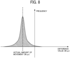
- FIG. 8 is a histogram representing a frequency distribution of difference values calculated by the displacement estimation unit 151 included in the displacement measurement device 100 according to an embodiment.
- the histogram illustrated in FIG. 8 represents a frequency distribution of difference values calculated by the displacement estimation unit 151 using the method described with reference to FIGs. 7A to 7C .
- the horizontal axis represents the difference value between coordinate values (X coordinates or Y coordinates), and the vertical axis represents the frequency.
- the histogram representing the frequency distribution of difference values has a peak at a certain difference value.
- the difference value at the peak is equal to the actual amount of translation (actual amount of movement) of the speckle image.
- the displacement estimation unit 151 can identify the mode of the difference values as the actual amount of translation of the speckle image. Based on the mode, the displacement estimation unit 151 can estimate the amount of displacement of the rough surface 10A of the measurement object 10.
- the displacement estimation unit 151 can directly compute differences between numerical sequences to calculate the amount of translation of a speckle image without generating two speckle images by the integration of two event data groups.
- the displacement estimation unit 151 can calculate the amount of displacement of the measurement object 10 at a high speed with reduced computational load.
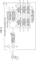
- FIG. 9 is a diagram illustrating an example functional configuration of the displacement estimation unit 151 included in the displacement measurement device 100 according to an embodiment.
- the displacement estimation unit 151 includes an event data group generation unit 171 and an element-specific numerical sequence generation unit 172.
- the event data group generation unit 171 acquires a predetermined number of items of event data output from the luminance-change coordinate point detection unit 130 and generates an event data group including the predetermined number of items of event data.
- the element-specific numerical sequence generation unit 172 generates a numerical sequence for each element in the event data group generated by the event data group generation unit 171. Specifically, the element-specific numerical sequence generation unit 172 generates a first numerical sequence including a set of X coordinates (an example of a "first element") and a second numerical sequence including a set of Y coordinates (an example of a "second element").
- the displacement estimation unit 151 includes the first numerical-sequence processing system P1 and the second numerical-sequence processing system P2.
- the first numerical-sequence processing system P1 performs computation of the first numerical sequence including the set of X coordinates (an example of a "first element") representing the locations of the luminance-change coordinate points extracted from the event data to calculate the amount of displacement of the measurement object 10 along the X coordinates.
- the second numerical-sequence processing system P2 performs computation of the second numerical sequence including the set of Y coordinates (an example of a "second element") representing the locations of the luminance-change coordinate points extracted from the event data to calculate the amount of displacement of the measurement object 10 along the Y coordinates.
- the first numerical-sequence processing system P1 and the second numerical-sequence processing system P2 each include a numerical-sequence correction unit 173, a computation-combination selection unit 174, and a displacement derivation unit 175.
- the numerical-sequence correction unit 173 performs predetermined correction on the first numerical sequence or the second numerical sequence.
- Examples of the predetermined correction include a process of extracting a luminance-change coordinate point of event data having either positive or negative polarity, and a sorting process.
- the computation-combination selection unit 174 selects combinations of luminance-change coordinate points to be subjected to computation for the first numerical sequence or the second numerical sequence that is corrected by the numerical-sequence correction unit 173. Specifically, the computation-combination selection unit 174 selects combinations of luminance-change coordinate points included in one event data group and luminance-change coordinate points included in the other event data group (e.g., round-robin combinations or combinations of corresponding luminance-change coordinate points in the descending orders).
- the displacement derivation unit 175 calculates difference values between coordinate values for each of the combinations of luminance-change coordinate points selected by the computation-combination selection unit 174. Then, the displacement derivation unit 175 identifies the mode of the calculated difference values as the actual amount of translation of the speckle image on the X axis or the Y axis. Based on the mode, the displacement derivation unit 175 estimates the amount of displacement of the measurement object 10 on the X axis or the Y axis. Further, the displacement derivation unit 175 outputs the estimated amount of displacement of the measurement object 10 on the X axis or the Y axis to the estimated displacement value output unit 152.
- the displacement estimation unit 151 does not include the numerical-sequence correction unit 173 or the computation-combination selection unit 174. In other words, in an example, the displacement estimation unit 151 does not correct numerical sequences or select combinations of luminance-change coordinate points to be subjected to computation. In this example, the displacement estimation unit 151 may automatically select "round-robin combinations".
- FIG. 10 is a flowchart illustrating an example operation procedure performed by the displacement estimation unit 151 included in the displacement measurement device 100 according to an embodiment.
- the event data group generation unit 171 acquires the event data output from the luminance-change coordinate point detection unit 130 (step S101). Subsequently, the event data group generation unit 171 stores the event data acquired in step S 101 in a memory included in the displacement measurement device 100 (step S102).
- the event data group generation unit 171 repeatedly performs the processing of steps S101 and S102 to store a predetermined number of (for example, 100) items of event data in the memory. Subsequently, the event data group generation unit 171 generates an event data group from the predetermined number of items of event data (step S 103).
- the event data group generation unit 171 performs the processing of steps S101 to S 103 twice to generate event data groups obtained at two different times.
- the element-specific numerical sequence generation unit 172 generates, for each of the two generated event data groups, a first numerical sequence including a set of X coordinates and a second numerical sequence including a set of Y coordinates (step S104).
- the numerical-sequence correction unit 173 performs predetermined correction (e.g., classification based on polarity, and sorting) on the first numerical sequence (step S105). Further, the computation-combination selection unit 174 selects combinations of luminance-change coordinate points to be subjected to computation for the first numerical sequence corrected in step S 105 (step S106). Subsequently, the displacement derivation unit 175 calculates difference values between coordinate values for all the combinations of luminance-change coordinate points selected in step S106, and identifies the mode of the calculated difference values as the actual amount of translation of the speckle image on the X axis. Based on the mode, the displacement derivation unit 175 estimates the amount of displacement of the measurement object 10 on the X axis (step S107).
- predetermined correction e.g., classification based on polarity, and sorting
- the numerical-sequence correction unit 173 performs predetermined correction (e.g., classification based on polarity, and sorting) on the second numerical sequence (step S108). Further, the computation-combination selection unit 174 selects combinations of luminance-change coordinate points to be subjected to computation for the second numerical sequence corrected in step S108 (step S109). Subsequently, the displacement derivation unit 175 calculates difference values between coordinate values for all the combinations of luminance-change coordinate points selected in step S109, and identifies the mode of the calculated difference values as the actual amount of translation of the speckle image on the Y axis. Based on the mode, the displacement derivation unit 175 estimates the amount of displacement of the measurement object 10 on the Y axis (step S110).
- predetermined correction e.g., classification based on polarity, and sorting
- the displacement derivation unit 175 outputs the amount of displacement of the measurement object 10 on the X axis, which is estimated in step S107, the amount of displacement of the measurement object 10 on the Y axis, which is estimated in step S110, to the estimated displacement value output unit 152 (step S111).
- the displacement estimation unit 151 ends the series of operations illustrated in FIG. 10 .
- the displacement estimation unit 151 repeatedly performs the series of operations illustrated in FIG. 10 to continuously estimate the amount of displacement of the measurement object 10 at a high speed.
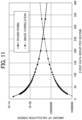
- FIG. 11 is a graph illustrating an example of the amount of calculation with the displacement estimation unit 151 included in the displacement measurement device 100 according to an embodiment.
- the graph illustrated in FIG. 11 depicts the amount of calculation to be performed with the displacement measurement device 100 when the event-based vision camera 131 including 320 ⁇ 240 picture elements outputs 10000 items of event data per second.
- the horizontal axis represents an event data group per second, which indicates the velocity resolution of a displacement.
- the value of the event data group per second is given by dividing n by the number of items of event data output per second.
- legends indicate the round-robin method, which is represented by a solid line with triangles, and the image correlation method, which is represented by a broken line with circles.
- the round-robin method is used for the displacement measurement device 100 according to an embodiment.
- the image correlation method is used for an existing displacement measurement device.
- the round-robin method is a method for calculating difference values for all combinations of all luminance-change coordinate points included in one event data group and all luminance-change coordinate points included in the other event data group and calculating the mode of the calculated difference values as the amount of displacement of the measurement object 10.
- the image correlation method is a method for determining the amount of displacement of the measurement object 10 from a correlation between two images generated from two event data groups.
- the round-robin method involves calculation of difference values for all combinations.
- the amount of calculation for determining difference values by round robin is given by O(n 2 )
- the amount of calculation for determining frequency distributions is given by O(n 2 ).
- the total amount of calculation is given by O(n 2 ).
- the amount of calculation for determining the amount of displacement of the measurement object 10 can be expressed by Equation (1) below.
- O n 2 O n 2 + O n 2
- the amount of calculation per operation is in proportion to the number n of items of event data included in the event data group.
- the event data group per second is in inverse proportion to the number n of items of event data included in the event data group. Therefore, the amount of calculation for the event data group per second is in an inverse proportional relationship.
- the amount of calculation per operation does not depend on the number n of items of event data included in the event data group.
- the amount of calculation for the event data group per second is substantially in proportion.
- the graph illustrated in FIG. 11 indicates that, in a situation in which the event data group per second exceeds about 275 (situation in which the measurement object 10 is displaced at a high speed), the round-robin method, which is used for the displacement measurement device 100 according to an embodiment, can estimate the amount of displacement of the measurement object 10 with a smaller amount of calculation than the image correlation method, which is used for the existing displacement measurement device.
- FIGs. 12A and 12B are illustrations of another example method for calculating the amount of displacement of the measurement object 10 by using the displacement estimation unit 151 included in the displacement measurement device 100 according to an embodiment.
- a method for calculating the amount of displacement of the measurement object 10 will be described typically using five luminance-change coordinate points included in an event data group.
- luminance-change coordinate points 700 are detected at times before the displacement of the rough surface 10A.
- luminance-change coordinate points 700' are detected at times after the displacement of the rough surface 10A.
- the luminance-change coordinate points 700' are obtained by translating the luminance-change coordinate points 700.
- the numbers assigned to the luminance-change coordinate points 700 and 700' represent the orders of the coordinate values on the Y axis that are sorted in descending order.
- the luminance-change coordinate points 700 and 700' illustrated in FIG. 12A are arranged on the same line (i.e., along the Y axis) in descending order of the coordinate values on the Y axis.
- the displacement estimation unit 151 calculates a difference value between the coordinate value of each of the five luminance-change coordinate points 700 and the coordinate value of the luminance-change coordinate point 700' having the same number.
- the displacement estimation unit 151 calculates a difference value between the coordinate value of the luminance-change coordinate point 700 assigned "1" and the coordinate value of the luminance-change coordinate point 700' assigned "1".
- the displacement estimation unit 151 calculates a difference value between the coordinate value of the luminance-change coordinate point 700 assigned "2" and the coordinate value of the luminance-change coordinate point 700' assigned "2".
- the displacement estimation unit 151 calculates a difference value between the coordinate value of the luminance-change coordinate point 700 assigned any other number and the coordinate value of the luminance-change coordinate point 700' assigned the same number.
- the displacement estimation unit 151 can calculate a difference value between each of the plurality of luminance-change coordinate points 700 and the luminance-change coordinate point 700' assigned the same number. In other words, the displacement estimation unit 151 can calculate a difference value equal to the total amount of translation. Accordingly, the displacement estimation unit 151 can calculate difference values with a smaller amount of computation than that in the round-robin method illustrated in FIGs. 7A to 7C .
- the displacement estimation unit 151 may calculate difference values between each of the five luminance-change coordinate points 700 and the luminance-change coordinate point 700' assigned the same number and a plurality of luminance-change coordinate points 700' assigned nearby numbers.
- the displacement estimation unit 151 may calculate a difference value between the luminance-change coordinate point 700 assigned "2" and the luminance-change coordinate point 700' assigned “2", a difference value between the luminance-change coordinate point 700 assigned "2” and the luminance-change coordinate points 700' assigned "1", and a difference value between the luminance-change coordinate point 700 assigned "2” and the luminance-change coordinate points 700' assigned "3".
- the displacement estimation unit 151 can calculate a difference value between each of the luminance-change coordinate points 700 and a corresponding one of the luminance-change coordinate points 700'.
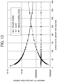
- FIG. 13 is a graph illustrating another example of the amount of calculation with the displacement estimation unit 151 included in the displacement measurement device 100 according to an embodiment.
- the graph illustrated in FIG. 13 depicts the amount of calculation to be performed with the displacement measurement device 100 when the event-based vision camera 131 including 320 ⁇ 240 picture elements outputs 10000 items of event data per second.
- legends indicate the round-robin method, which is represented by a solid line with triangles, the image correlation method, which is represented by a broken line with circles, and the sort method, which is represented by a dash-dot line with rectangles.
- the sort method is another method used for the displacement measurement device 100 according to an embodiment.
- the range of the target luminance-change coordinate points (corresponding to corresponding ones of the luminance-change coordinate points 700' illustrated in FIGs. 12A and 12B ) is set to "the same number ⁇ 3". In other words, the number of target luminance-change coordinate points (the number of nearby areas) is set to "7".
- the sort method involves a calculation of nlog(n) to sort a sequence of numbers in an event data group.
- a calculation of 2nlog(n) is used to calculate the calculation on two sequences of numbers.
- the sort method involves a calculation of 7n, where the number of items of event data included in the event data group is represented by n and the number of target luminance-change coordinate points (the number of nearby areas) is represented by "7".
- the sort method involves a calculation of O(nlogn) to sort a sequence of numbers in an event data group, a calculation of O(n) for coordinate difference calculation, and a calculation of O(n) for frequency distribution calculation.
- the sort method involves a calculation of O(nlogn) in total.
- Equation (3) the amount of calculation for determining the amount of displacement of the measurement object 10 can be expressed by Equation (3) below.
- O nlogn O nlogn + O n
- the amount of calculation per operation is in proportion to nlog(n).
- the event data group per second is in inverse proportion to the number n of items of event data included in the event data group. Accordingly, the amount of calculation for the event data group per second is in proportion to log(n). When n is large, the amount of calculation is substantially constant.
- the graph illustrated in FIG. 13 indicates that the sort method can estimate the amount of displacement of the measurement object 10 with a smaller amount of calculation than the round-robin method.
- FIG. 14 is a diagram illustrating another example functional configuration of the displacement estimation unit 151 included in the displacement measurement device 100 according to an embodiment.
- the event-based vision camera 131 of the luminance-change coordinate point detection unit 130 includes a light-receiving element 131A having an exposure area 131B.
- the exposure area 131B is scanned in the X-axis direction over time. Accordingly, the X-coordinate values of the event data output from the event-based vision camera 131 are periodically sorted in advance.
- the displacement estimation unit 151 sorts only the second numerical sequence on the Y-axis, and the numerical-sequence correction unit 173 of the first numerical-sequence processing system P1 may be omitted. In the displacement measurement device 100 illustrated in FIG. 14 , therefore, the amount of computation performed by the displacement estimation unit 151 can further be reduced.
- FIG. 15 is a diagram illustrating still another example functional configuration of the displacement estimation unit 151 included in the displacement measurement device 100 according to an embodiment.
- the displacement measurement device 100 illustrated in FIG. 15 is different from the displacement measurement device 100 illustrated in FIG. 9 in that the first numerical-sequence processing system P1 and the second numerical-sequence processing system P2 each include a frequency-distribution array generation unit 176 in place of the numerical-sequence correction unit 173.
- the frequency-distribution array generation unit 176 generates two frequency-distribution arrays from two event data groups obtained at different times.
- the displacement measurement device 100 illustrated in FIG. 15 is further different from the displacement measurement device 100 illustrated in FIG. 9 in that the displacement derivation unit 175 in each of the first numerical-sequence processing system P1 and the second numerical-sequence processing system P2 uses a convolution operation method instead of the round-robin method to calculate the amount of displacement of the measurement object 10.
- the displacement measurement device 100 illustrated in FIG. 15 is further different from the displacement measurement device 100 illustrated in FIG. 9 in that the first numerical-sequence processing system P1 and the second numerical-sequence processing system P2 each do not include the computation-combination selection unit 174.
- the method for calculating the amount of displacement of the measurement object 10 by using the convolution operation method, which is performed by the displacement derivation units 175 included in the displacement measurement device 100 illustrated in FIG. 15 , will be described, with focus on the X-axis coordinate elements of the event data groups.
- the number of sensors of an event camera in the X-axis direction is denoted by M
- a chronologically earlier event data group is denoted by A
- a chronologically later event data group is denoted by B.
- the event data group A includes N items of event data, and the X coordinates of the N items of event data are represented by Ax0, Ax1, Ax2, ..., and AxN-1.
- the event data group B includes N items of event data, and the X coordinates of the N items of event data are represented by Bx0, Bx1, Bx2, ..., and BxN-1.
- Arrays focusing on the numbers of items of event data having the same coordinate among the coordinates Ax and Bx, which are respectively the coordinate information of the event data groups A and B, are denoted by s and t, respectively.
- the number of items of event data having Ax expressed by M - 1 - i within the event data group A is defined as s[i].
- the number of items of event data having Bx expressed by i within the event data group B is defined as t[i].
- an array d obtained by Equation (4) below can be defined.
- the array D can be calculated by the following equation.
- the array D (first array) is further subjected to an inverse discrete Fourier transform to obtain the array d (second array). Since the array d indicates the frequency of a difference coordinate, the mode of the array d is extracted to estimate the amount of translation of the speckle.
- the frequency of a difference between numerical sequences is determined by using a discrete Fourier transform. It is thus preferable that the first numerical-sequence processing system P1 and the second numerical-sequence processing system P2 each include an FPGA, a GPU, or the like that can perform advanced computational processing.
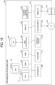
- FIG. 16 is a diagram illustrating an example hardware configuration of the information processing unit 150 included in the displacement measurement device 100 according to an embodiment.
- FIG. 16 illustrates an example hardware configuration of the information processing unit 150 in a case where the information processing unit 150 is implemented by a personal computer.
- the information processing unit 150 is implemented by a computer and includes central processing units (CPUs) 201A and 201B, a read-only memory (ROM) 202, a random access memory (RAM) 203, a hard disk (HD) 204, a hard disk drive (HDD) controller 205, a display 206, an external device connection interface (I/F) 208, a network I/F 209, a data bus 210, a keyboard 211, a pointing device 212, a digital versatile disc rewritable (DVD-RW) drive 214, and a media I/F 216.
- CPUs central processing units
- ROM read-only memory
- RAM random access memory
- HD hard disk
- HDD hard disk drive
- display 206 a display 206
- I/F external device connection interface
- network I/F 209 a data bus 210
- keyboard 211 a keyboard 211
- a pointing device 212 a digital versatile disc rewritable (DV
- the CPUs 201A and 201B control the overall operation of the information processing unit 150.
- the ROM 202 stores a program such as an initial program loader (IPL) to boot the CPUs 201A and 201B.
- the RAM 203 is used as a work area for the CPUs 201A and 201B.
- the HD 204 stores various data such as a program.
- the HDD controller 205 controls reading or writing of various data from or to the HD 204 under the control of the CPUs 201A and 201B.
- the display 206 displays various kinds of information such as a cursor, a menu, a window, text, or an image.
- the external device connection I/F 208 is an interface for connecting to various external devices. Examples of the external devices include, but are not limited to, a universal serial bus (USB) memory and a printer.
- the network I/F 209 is an interface for performing data communication using a communication network.
- the data bus 210 is an address bus, a data bus, or the like for electrically connecting various components illustrated in FIG. 16 , such as the CPUs 201A and 201B, to each other.
- the keyboard 211 is an example of an input unit provided with a plurality of keys to allow the user to enter characters, numerical values, or various instructions.
- the pointing device 212 is an example of an input unit that allows the user to select or execute a specific instruction, select a target for processing, or move a cursor being displayed.
- the DVD-RW drive 214 controls reading or writing of various data from or to a DVD-RW 213, which is an example of a removable recording medium.
- the removable recording medium is not limited to a DVD-RW and may be a digital versatile disc recordable (DVD-R), for example.
- the media I/F 216 controls reading or writing (storing) of data from or to a recording medium 215 such as a flash memory.
- the information processing unit 150 includes two CPUs (i.e., the CPUs 201A and 201B).
- the CPU 201A executes processing of the first numerical-sequence processing system P1.
- the CPU 201B executes processing of the second numerical-sequence processing system P2.
- the CPUs 201A and 201B can execute processing operations in parallel with each other. Accordingly, the information processing unit 150 can execute, in parallel, computation of the first numerical sequence by using the CPU 201A (i.e., the first numerical-sequence processing system P1) and computation of the second numerical sequence by using the CPU 201B (i.e., the second numerical-sequence processing system P2).
- the first numerical-sequence processing system P1 and the second numerical-sequence processing system P2 may be any combination of hardware components that can execute processing operations in parallel with each other.
- the first numerical-sequence processing system P1 and the second numerical-sequence processing system P2 are not limited to a combination of two CPUs, and a combination of two computation circuits may be used.
- a combination of two computers or any other suitable combination of hardware components may be used.
- FIG. 17 is a schematic view of a non-contact input apparatus 1100, which is a first example implementation of the displacement measurement device 100 according to an embodiment.
- FIG. 18 is a diagram illustrating the cross section of the non-contact input apparatus 1100, which is the first example implementation of the displacement measurement device 100 according to the embodiment.
- the non-contact input apparatus 1100 includes a housing 1101, an image display unit 1102, an image forming plate 1103, an optical window 1104, a non-contact input identification unit 1105, and a displacement measurement device 100.
- the non-contact input apparatus 1100 may include the displacement measurement device 100 according to an embodiment.
- the illustration of the interference pattern forming unit 120 included in the displacement measurement device 100 is omitted.
- the irradiation unit 110 included in the displacement measurement device 100 emits coherent light, which emerges as a light sheet, upward and forward from the housing 1101.
- the irradiation unit 110 emits coherent light near a virtual image formed by the image display unit 1102 and the image forming plate 1103.
- the measurement object 10 e.g., the finger of the operator
- reflected light of the light sheet from the measurement object 10 is incident on the luminance-change coordinate point detection unit 130 included in the displacement measurement device 100 in the housing 1101 through the optical window 1104 as an interference pattern.
- the information processing unit 150 included in the displacement measurement device 100 can detect the amount of micro-displacement of the measurement object 10 and output information indicating the detected amount of micro-displacement of the measurement object 10 to the non-contact input identification unit 1105.
- the non-contact input identification unit 1105 can accurately detect the non-contact operation made by the measurement object 10 (e.g., a push of the finger, handwriting, or a swipe of the finger), based on the information output from the displacement measurement device 100, which indicates the amount of micro-displacement of the measurement object 10. Further, the non-contact input identification unit 1105 can output the detection result to an operation target apparatus (not illustrated) or feed back the detection result to the operator.
- the non-contact input identification unit 1105 may be implemented by, for example, a PC, which may include a processor, memory, and interface.
- the image forming plate 1103 may be used to form a virtual image from video information or an image displayed on the image display unit 1102 and display the virtual image above and in front of the housing 1101 to improve the operability.
- the image forming plate 1103 is a member having characteristics of transmission and deflection of light beams.
- the image forming plate 1103 is implemented by a layered reflection structure.
- the displacement measurement device 100 can quickly and reliably capture a small non-contact movement of the measurement object 10 (the finger of the operator). In other words, the displacement measurement device 100 can accurately detect a non-contact operation of the measurement object 10 (the finger of the operator).
- FIG. 19 is a schematic view of a tremor measurement apparatus 1200, which is a second example implementation of the displacement measurement device 100 according to an embodiment.
- FIG. 20 is a diagram illustrating the cross section of the tremor measurement apparatus 1200, which is the second example implementation of the displacement measurement device 100 according to the embodiment.
- the tremor measurement apparatus 1200 includes a housing 1201, a cylindrical lens 1202, a turning mirror 1203, an optical window 1204, a support 1205, a display device 1206, and a displacement measurement device 100.
- the tremor measurement apparatus 1200 is an example of a "biological micromotion measurement apparatus".
- the tremor measurement apparatus 1200 may include the displacement measurement device 100 according to an embodiment.
- the illustration of the interference pattern forming unit 120 included in the displacement measurement device 100 is omitted.
- the cylindrical lens 1202, the turning mirror 1203, and the optical window 1204 are collectively referred to as an optical system.
- the tremor measurement apparatus 1200 illustrated in FIGs. 19 and 20 is an apparatus configured to detect slight movements (e.g., tremors) of a living organism, which is the measurement object 10.
- Tremor is an involuntary movement caused by alternating contraction and relaxation of muscles. Trembling of the hand is a typical example of tremors. Tremors may be caused by conditions such as stress, anxiety, fatigue, hyperthyroidism, and alcoholic withdrawal. Rest tremor is one of the main symptoms in Parkinson's disease.
- the tremor is measured by measurement of the myoelectric potential or with an acceleration sensor.
- the tremor measurement apparatus 1200 illustrated in FIGs. 19 and 20 including the displacement measurement device 100 can capture micro-vibrations of the measurement object 10 on the micrometer level. As a result, the tremor can be measured with high accuracy in a non-contact environment.
- the tremor measurement apparatus 1200 measures the tremor with the angle between the elbow and the forearm being kept at 45 degrees relative to the horizontal support 1205.
- the irradiation unit 110 emits coherent light to the back of the hand, and reflected light of the coherent light from the back of the hand is incident on the luminance-change coordinate point detection unit 130 as an interference pattern.
- the information processing unit 150 included in the displacement measurement device 100 can detect the amount of micro-displacement of the measurement object 10.
- the information processing unit 150 can measure the tremor of the measurement object 10 with high accuracy.
- the tremor data measured by the displacement measurement device 100 is subjected to frequency analysis or the like and can be used to help understand the condition of the person (i.e., the operator) or used as medical data.
- the functions of the "displacement measurement device” may be physically implemented by one device or physically implemented by a plurality of devices.
- a plurality of devices that implements the "displacement measurement device” may be referred to as a "displacement measurement system”.
- the "displacement measurement device” may be applied to apparatuses other than a “biological micromotion measurement apparatus” and a “non-contact input apparatus". In embodiments of the present disclosure, the “displacement measurement device” may be applied to a game console, an input/output apparatus, and so on. In embodiments of the present disclosure, the “displacement measurement device” may be applied not only to an apparatus that uses the detection of micro-displacement but also to an apparatus for removing small movement errors.
- the present invention can be implemented in any convenient form, for example using dedicated hardware, or a mixture of dedicated hardware and software.
- the present invention may be implemented as computer software implemented by one or more networked processing apparatuses.
- the processing apparatuses include any suitably programmed apparatuses such as a general purpose computer, a personal digital assistant, a Wireless Application Protocol (WAP) or third-generation (3G)-compliant mobile telephone, and so on. Since the present invention can be implemented as software, each and every aspect of the present invention thus encompasses computer software implementable on a programmable device.
- the computer software can be provided to the programmable device using any conventional carrier medium (carrier means).
- the carrier medium includes a transient carrier medium such as an electrical, optical, microwave, acoustic or radio frequency signal carrying the computer code.
- transient medium is a Transmission Control Protocol/Internet Protocol (TCP/IP) signal carrying computer code over an IP network, such as the Internet.
- the carrier medium may also include a storage medium for storing processor readable code such as a floppy disk, a hard disk, a compact disc read-only memory (CD-ROM), a magnetic tape device, or a solid state memory device.
- a displacement measurement system includes: an irradiation unit configured to irradiate a measurement object with coherent light; a luminance-change coordinate point detection unit configured to detect a luminance-change coordinate point where a luminance change has occurred, based on light reflected from the measurement object, and output data related to the luminance-change coordinate point; and circuitry configured to calculate an amount of displacement of the measurement object, based on the data related to the luminance-change coordinate point, by performing computations of a first numerical sequence and a second numerical sequence.
- the first numerical sequence including a set of first elements each representing a location of the luminance-change coordinate point extracted from the data.
- the second numerical sequence including a set of second elements each representing a location of the luminance-change coordinate point extracted from the data.
Landscapes
- Engineering & Computer Science (AREA)
- Physics & Mathematics (AREA)
- General Physics & Mathematics (AREA)
- Multimedia (AREA)
- Theoretical Computer Science (AREA)
- Computer Vision & Pattern Recognition (AREA)
- General Health & Medical Sciences (AREA)
- Health & Medical Sciences (AREA)
- Social Psychology (AREA)
- Human Computer Interaction (AREA)
- Psychiatry (AREA)
- Electromagnetism (AREA)
- Signal Processing (AREA)
- Computer Networks & Wireless Communication (AREA)
- Radar, Positioning & Navigation (AREA)
- Remote Sensing (AREA)
- Life Sciences & Earth Sciences (AREA)
- Biomedical Technology (AREA)
- Molecular Biology (AREA)
- Length Measuring Devices By Optical Means (AREA)
Abstract
A displacement measurement device includes: an irradiation unit (110) configured to irradiate a measurement object with coherent light; a luminance-change coordinate point detection unit (130) configured to detect a luminance-change coordinate point where a luminance change has occurred, based on light reflected from the measurement object, and output data related to the luminance-change coordinate point; and a displacement estimation unit (151) configured to estimate an amount of displacement of the measurement object, based on the data related to the luminance-change coordinate point. The displacement estimation unit (151) includes: a first numerical-sequence processing system (P1) configured to perform computation of a first numerical sequence including a set of first elements each representing a location of the luminance-change coordinate point extracted from the data to calculate the amount of displacement of the measurement object along the first elements; and a second numerical-sequence processing system (P2) configured to perform computation of a second numerical sequence including a set of second elements each representing a location of the luminance-change coordinate point extracted from the data to calculate the amount of displacement of the measurement object along the second elements.
Description
- The present disclosure relates to a displacement measurement device, a non-contact input apparatus, and a biological micromotion measurement apparatus.
- A technique for measuring the amount of micro-displacement of a measurement object is disclosed in Zhou Ge., Yizhao Gao., Hayden K.-h. So., and Edmund Y Lam., "Event-based laser speckle correlation for micro motion estimation", Optics Letters, volume 46, no. 16/15, August 2021, pp. 3885 to 3888. In the disclosed technique, speckle patterns are acquired using an event-based vision sensor to generate speckle pattern images, and image processing is performed on the speckle pattern images to measure the amount of micro-displacement of the measurement object.
- In an existing object displacement measurement technique using an event-based vision sensor and speckle pattern images, event information output from photodetectors in an asynchronous manner is accumulated for a certain amount of time and is converted into images, and existing image processing is applied to the images to calculate the amounts of translation of the speckle pattern images. Such a technique involves a relatively large amount of computation in spite of the use of an event-based vision sensor, and the amount of displacement of the measurement object is difficult to detect at a high speed.
- According to an embodiment of the present disclosure, a displacement measurement device includes an irradiation unit, a luminance-change coordinate point detection unit, and a displacement estimation unit. The irradiation unit irradiates a measurement object with coherent light. The luminance-change coordinate point detection unit detects a luminance-change coordinate point where a luminance change has occurred, based on light reflected from the measurement object, and outputs data related to the luminance-change coordinate point. The displacement estimation unit estimates an amount of displacement of the measurement object, based on the data related to the luminance-change coordinate point. The displacement estimation unit includes a first numerical-sequence processing system and a second numerical-sequence processing system. The first numerical-sequence processing system performs computation of a first numerical sequence including a set of first elements each representing a location of the luminance-change coordinate point extracted from the data to calculate the amount of displacement of the measurement object along the first elements. The second numerical-sequence processing system performs computation of a second numerical sequence including a set of second elements each representing a location of the luminance-change coordinate point extracted from the data to calculate the amount of displacement of the measurement object along the second elements.
- According to an embodiment of the present disclosure, a non-contact input apparatus includes the displacement measurement device and a non-contact input identification unit that detects a non-contact operation based on information indicating the amount of displacement output from the displacement measurement device.
- According to an embodiment of the present disclosure, a biological micromotion measurement apparatus includes the displacement measurement device and an optical system that receives reflected light from the measurement object. The reflected light results from light emitted from the displacement measurement device. The measurement object includes a living organism. The displacement measurement device detects an amount of micro-displacement of the measurement object by using the reflected light.
- At least one embodiment provides a displacement measurement device that can detect the amount of displacement of a measurement object at a high speed with reduced computational load.
- A more complete appreciation of embodiments of the present disclosure and many of the attendant advantages and features thereof can be readily obtained and understood from the following detailed description with reference to the accompanying drawings, wherein:
-
FIG. 1 is a diagram illustrating the general arrangement of a displacement measurement device according to a first embodiment; -
FIG. 2 is a diagram illustrating an example configuration of a luminance-change coordinate point detection unit included in the displacement measurement device according to the first embodiment; -
FIG. 3 is a diagram illustrating another example configuration of the luminance-change coordinate point detection unit included in the displacement measurement device according to the first embodiment; -
FIGs. 4A to 4C are illustrations of an example of event data output by the luminance-change coordinate point detection unit included in the displacement measurement device according to the first embodiment; -
FIGs. 5A to 5C are illustrations of the principle of displacement estimation using a displacement estimation unit included in the displacement measurement device according to the first embodiment; -
FIGs. 6A to 6C are illustrations of the principle of a method for estimating the amount of displacement of a measurement object by using the displacement estimation unit according to an embodiment; -
FIGs. 7A to 7C are illustrations of an example method for calculating the amount of displacement of a measurement object by using the displacement estimation unit included in the displacement measurement device according to an embodiment; -
FIG. 8 is a histogram representing a frequency distribution of difference values calculated by the displacement estimation unit included in the displacement measurement device according to an embodiment; -
FIG. 9 is a diagram illustrating an example functional configuration of the displacement estimation unit included in the displacement measurement device according to an embodiment; -
FIG. 10 is a flowchart illustrating an example operation procedure performed by the displacement estimation unit included in the displacement measurement device according to an embodiment; -
FIG. 11 is a graph illustrating an example of the amount of calculation with the displacement estimation unit included in the displacement measurement device according to an embodiment; -
FIGs. 12A and 12B are illustrations of another example method for calculating the amount of displacement of a measurement object by using the displacement estimation unit included in the displacement measurement device according to an embodiment; -
FIG. 13 is a graph illustrating another example of the amount of calculation with the displacement estimation unit included in the displacement measurement device according to an embodiment; -
FIG. 14 is a diagram illustrating another example functional configuration of the displacement estimation unit included in the displacement measurement device according to an embodiment; -
FIG. 15 is a diagram illustrating still another example functional configuration of the displacement estimation unit included in the displacement measurement device according to an embodiment; -
FIG. 16 is a diagram illustrating an example hardware configuration of an information processing unit included in the displacement measurement device according to an embodiment; -
FIG. 17 is a schematic view of a non-contact input apparatus that is a first example implementation of the displacement measurement device according to an embodiment; -
FIG. 18 is a diagram illustrating the cross section of the non-contact input apparatus that is the first example implementation of the displacement measurement device according to the embodiment; -
FIG. 19 is a schematic view of a tremor measurement apparatus that is a second example implementation of the displacement measurement device according to an embodiment; and -
FIG. 20 is a diagram illustrating the cross section of the tremor measurement apparatus that is the second example implementation of the displacement measurement device according to the embodiment. - The accompanying drawings are intended to depict embodiments of the present disclosure and should not be interpreted to limit the scope thereof. The accompanying drawings are not to be considered as drawn to scale unless explicitly noted. Also, identical or similar reference numerals designate identical or similar components throughout the several views.
- In describing embodiments illustrated in the drawings, specific terminology is employed for the sake of clarity. However, the disclosure of this specification is not intended to be limited to the specific terminology so selected and it is to be understood that each specific element includes all technical equivalents that have a similar function, operate in a similar manner, and achieve a similar result.
- Referring now to the drawings, embodiments of the present disclosure are described below. As used herein, the singular forms "a," "an," and "the" are intended to include the plural forms as well, unless the context clearly indicates otherwise.
- Embodiments will be described hereinafter with reference to the drawings.
-
FIG. 1 is a diagram illustrating the general arrangement of adisplacement measurement device 100 according to a first embodiment. Thedisplacement measurement device 100 illustrated inFIG. 1 is a device configured to irradiate a measurement object 10 (e.g., a hand of a person) with coherent light, detect a luminance-change coordinate point based on reflected light from themeasurement object 10, and measure the amount of micro-displacement of themeasurement object 10 based on event data related to the detected luminance-change coordinate point. - The term "luminance-change coordinate point" refers to a pixel where a certain amount or more of luminance change has occurred on an image sensor. The term "event data" refers to data related to a pixel whose luminance has changed a certain amount or more and including the time (T) of the luminance change, the location (X, Y) of the luminance change, and the polarity (P) of the luminance change.
- The amount of micro-displacement of the
measurement object 10, which is measured by thedisplacement measurement device 100, is output to, for example, an apparatus external to thedisplacement measurement device 100 and is used by the external apparatus for display to a user or control of an external apparatus to be controlled. - As illustrated in
FIG. 1 , thedisplacement measurement device 100 includes an irradiation unit 110 (also referred to as a "light projection unit"), an interferencepattern forming unit 120, a luminance-change coordinatepoint detection unit 130, and aninformation processing unit 150. - The
irradiation unit 110 irradiates themeasurement object 10 with coherent light. Theirradiation unit 110 is preferably a laser light source having high coherence to form an interference pattern of light reflected from themeasurement object 10 on a light-receiving surface of the luminance-change coordinatepoint detection unit 130. Examples of theirradiation unit 110 include a laser diode (LD), a vertical-cavity surface-emitting laser (VCSEL), a small gas laser, and a solid state laser. - The interference
pattern forming unit 120 forms an interference pattern from light reflected from the measurement object 10 (i.e., from coherent light reflected from the measurement object 10). In this embodiment, the interferencepattern forming unit 120 is disposed on an optical path of light reflected from themeasurement object 10 between themeasurement object 10 and the luminance-change coordinatepoint detection unit 130. The interferencepattern forming unit 120 has a function of adjusting the characteristics of an interference pattern received on the light-receiving surface of the luminance-change coordinatepoint detection unit 130 so that the amount of displacement of themeasurement object 10 can be appropriately acquired. In an example, the interferencepattern forming unit 120 includes a so-called wavefront control element such as a lens, an aperture, a phase shifter, or a spatial light modulator (SLM). - An example of interference patterns formed by the interference
pattern forming unit 120 is a speckle image. The speckle image refers to random interference patterns caused by the roughness of the surface of themeasurement object 10. The speckle image reflects the characteristics of light as a wave motion, and has a luminance distribution that changes sensitively to the movement of themeasurement object 10. In other words, the speckle image is obtained by converting the sensitivity into a scale such that micro-displacement of themeasurement object 10 is captured by the light-receiving surface of the luminance-change coordinatepoint detection unit 130. - The luminance-change coordinate
point detection unit 130 receives, on the light-receiving surface, the interference pattern formed by the interferencepattern forming unit 120, and detects a luminance-change coordinate point where a certain amount or more of luminance change has occurred, based on the received interference pattern. The luminance-change coordinatepoint detection unit 130 outputs event data related to the detected luminance-change coordinate point. An example configuration of the luminance-change coordinatepoint detection unit 130 will be described below with reference toFIGs. 2 and 3 . - The
information processing unit 150 includes adisplacement estimation unit 151 and an estimated displacementvalue output unit 152. - The
displacement estimation unit 151 calculates an estimated value of the amount of displacement of themeasurement object 10 in a real space, based on the event data output from the luminance-change coordinatepoint detection unit 130. - The estimated displacement
value output unit 152 outputs the estimated value of the amount of displacement of themeasurement object 10, which is calculated by thedisplacement estimation unit 151. - In the
displacement measurement device 100 according to the first embodiment, thedisplacement estimation unit 151 is configured to calculate an estimated value of the amount of displacement of themeasurement object 10 in a real space by using two numerical-sequence processing systems. The two numerical-sequence processing systems are provided in parallel in terms of hardware for two numerical sequences of two elements (the X coordinate and the Y coordinate) representing the locations of luminance-change coordinate points. - In other words, the
displacement estimation unit 151 is configured to perform the two calculations in parallel. One of the calculations is performed by a first numerical-sequence processing system P1, and the other calculation is performed by a second numerical-sequence processing system P2. The first numerical-sequence processing system P1 calculates the amount of displacement of themeasurement object 10 along the X axis based on the numerical sequence of X-coordinate values. The second numerical-sequence processing system P2 calculates the amount of displacement of themeasurement object 10 along the Y axis based on the numerical sequence of Y-coordinate values. As used herein, the term "in parallel" means that operations can be performed independently of each other, and is used to include a case where time periods during which the operations are performed partially overlap. - Accordingly, the
displacement measurement device 100 according to the first embodiment can detect the amount of displacement of themeasurement object 10 at a high speed with reduced computational load. - Each of the functions of the
information processing unit 150 can be implemented by one or more processing circuits or circuitry. As used herein, the term "processing circuit or circuitry" is used to include a processor programmed to implement each function by software, such as a processor implemented by an electronic circuit, and devices designed to implement the functions described above, such as an application specific integrated circuit (ASIC), a digital signal processor (DSP), a field programmable gate array (FPGA), and existing circuit modules. Example Configuration of Luminance-Change CoordinatePoint Detection Unit 130 -
FIG. 2 is a diagram illustrating an example configuration of the luminance-change coordinatepoint detection unit 130 included in thedisplacement measurement device 100 according to the first embodiment. - In the example illustrated in
FIG. 2 , the luminance-change coordinatepoint detection unit 130 includes an event-basedvision camera 131. - The event-based
vision camera 131 is equipped with an event-based vision sensor. The event-based vision sensor is configured to receive an interference pattern, instantaneously (i.e., in a very short time and at a very high speed) detect a luminance-change coordinate point where a certain amount or more of luminance change has occurred in a two-dimensional array of pixels, and output event data including the time (T) of the luminance change, the location (X, Y) of the luminance change, and the polarity (P) of the luminance change. Accordingly, the event-basedvision camera 131 can directly generate event data. - In the
displacement measurement device 100, the event-basedvision camera 131 of the luminance-change coordinatepoint detection unit 130 is used to quickly acquire a speckle image that sensitively changes and reliably capture micro-displacement of themeasurement object 10. -
FIG. 3 is a diagram illustrating another example configuration of the luminance-change coordinatepoint detection unit 130 included in thedisplacement measurement device 100 according to the first embodiment. - In the example illustrated in
FIG. 3 , the luminance-change coordinatepoint detection unit 130 includes aframe camera 132, a frame-to-frame luminancedifference computation unit 133, and a luminance-change coordinatepoint extraction unit 134. The frame-to-frame luminancedifference computation unit 133 and a luminance-change coordinatepoint extraction unit 134 are implemented by circuitry, such as a CPU. - The
frame camera 132 captures a normal frame image in which the interference pattern appears, and outputs the frame image. The frame-to-frame luminancedifference computation unit 133 calculates a luminance difference between corresponding pixels in two continuous frame images output from theframe camera 132. The luminance-change coordinatepoint extraction unit 134 extracts, as a luminance-change coordinate point, a pixel where a luminance difference greater than or equal to a certain value is calculated by the frame-to-frame luminancedifference computation unit 133. The luminance-change coordinatepoint extraction unit 134 outputs event data related to the extracted luminance-change coordinate point. The event data includes the time (T) of the luminance change, the location (X, Y) of the luminance change, and the polarity (P) of the luminance change. -
FIGs. 4A to 4C are illustrations of an example of event data output by the luminance-change coordinatepoint detection unit 130 included in thedisplacement measurement device 100 according to the first embodiment. -
FIGs. 4A and 4B illustrate examples of a speckle image formed on a light-receiving surface of the event-based vision sensor included in the event-basedvision camera 131.FIG. 4A illustrates aspeckle image 400A at time t.FIG. 4B illustrates aspeckle image 400B at time t + Δt.FIG. 4C illustratesevent data 410, which is an example of the event data output from the event-basedvision camera 131. Theevent data 410 is generated based on thespeckle image 400A illustrated inFIG. 4A and thespeckle image 400B illustrated inFIG. 4B . - The event-based vision sensor included in the event-based
vision camera 131 is a photodetector that outputs event data. In response to detection of a pixel (i.e., a luminance-change coordinate point) where a luminance change exceeding a predetermined threshold has occurred among pixels arranged in a two-dimensional array (i.e., in response to the occurrence of an event), the event-based vision sensor outputs, as event data, data including the time (T) of the luminance change, the location (X, Y) of the luminance change, and the polarity (P) of the luminance change. The polarity (P) may have a binary value, namely, "1" for increase or "0" for decrease. - In an example, the
speckle image 400A at the time t illustrated inFIG. 4A is horizontally translated, and, after Δt, thespeckle image 400B at the time t + Δt illustrated inFIG. 4B is produced. In this case, as indicated by theevent data 410 illustrated inFIG. 4C , with the polarities of luminance changes on the event-based vision sensor at the time t + Δt, the speckles are spatially distributed withdecrease components 410A and increasecomponents 410B. InFIG. 4C , thedecrease components 410A are represented as lightly shaded regions, and theincrease components 410B are represented as heavily shaded regions. In thedecrease components 410A, the luminance values are decreased by a value greater than or equal to a certain value. In theincrease components 410B, the luminance values are increased by a value greater than or equal to a certain value. - The event-based vision sensor outputs, for all the pixels in the
increase components 410B, a time-series data group of signals including the times (T) of signal detection, the pixel locations (X, Y), and the polarity ("1": increase). The event-based vision sensor also outputs, for all the pixels in thedecrease components 410A, a time-series data group of signals including the times (T) of signal detection, the pixel locations (X, Y), and the polarity ("0": decrease). The event-based vision sensor does not output data for the pixels in the other regions (non-shaded regions inFIG. 4C ) that do not correspond to either the region of thedecrease components 410A or the region of theincrease components 410B. Accordingly, theevent data 410 output from the event-based vision sensor has a much smaller amount of data than frame image data. - In this manner, the event-based vision sensor has no limitation in terms of frame rate and can output, as event data, shift information between speckle images at a higher speed than an image sensor that outputs frame image data.
- For example, the event-based vision sensor has a sampling time of about 1 µs to 200 µs for all event data in the sensor surface. The sampling time of the event-based vision sensor is much faster than the frame rate of an ordinary video camera or the like. Accordingly, the event-based vision sensor included in the luminance-change coordinate
point detection unit 130 can quickly and reliably detect a shift between speckle images, which changes sensitively to the displacement of themeasurement object 10. -
FIGs. 5A to 5C are illustrations of the principle of displacement estimation using thedisplacement estimation unit 151 included in thedisplacement measurement device 100 according to the first embodiment. -
FIGs. 5A and 5B illustrate examples of a frame image based on the event data output from the event-basedvision camera 131.FIG. 5A illustrates aframe image 500A at time t.FIG. 5B illustrates aframe image 500B at time t + Δts. In theframe images FIG. 5C illustrates an example of a cross-correlation function calculated based on theframe images - First, in the principle of displacement estimation, to obtain the
frame image 500A illustrated inFIG. 5A from the time-series event data output from the event-basedvision camera 131, an integration time for calculating unit frames is set, a two-dimensional matrix representing an image is prepared, and the number of times a row and column number corresponding to a pixel location appears in the integration time is counted. - Subsequently, in the principle of displacement estimation, as illustrated in
FIG. 5B , the time of theframe image 500A illustrated inFIG. 5A , for example, a time distant from the integration start time (t) by Δts, is set as the start point of integration, and the number of times the row and column number appears in the integration time is also counted. - In the
frame image 500B illustrated inFIG. 5B , dotted-line portions represent patterns in theframe image 500A illustrated inFIG. 5A . The patterns are translated to lightly shaded locations in theframe image 500B illustrated inFIG. 5B . - Subsequently, in the principle of displacement estimation, a cross-correlation function (see
FIG. 5C ) between theframe image 500A and theframe image 500B is calculated. - As illustrated in
FIG. 5C , when a variable of the correlation function, that is, an amount of displacement, is plotted on the ΔX axis and the ΔY axis, a peak value of the cross-correlation function is obtained at a distance and location (an amount of pixel displacement in the image) corresponding to the amount of translation of the speckle pattern. For example, in the principle of displacement estimation, any one of theframe images frame images FIG. 5C . - In the principle of displacement estimation, in an example, the following method (the Wiener-Khinchin theorem) may be used to calculate the cross-correlation function: The
frame images frame images frame images -
FIGs. 6A to 6C are illustrations of the principle of a method for estimating the amount of displacement of a measurement object by using thedisplacement estimation unit 151 according to an embodiment. -
FIG. 6A illustrates an optical system included in thedisplacement measurement device 100 according to an embodiment.FIG. 6B illustrates an example of event data groups output from the event-basedvision camera 131 included in thedisplacement measurement device 100 according to an embodiment.FIG. 6C illustrates an image of event data groups at two different times. - As illustrated in
FIG. 6A , thedisplacement measurement device 100 irradiates arough surface 10A, which is themeasurement object 10, with coherent light from theirradiation unit 110 and receives light reflected from therough surface 10A on the light-receiving surface of the luminance-change coordinatepoint detection unit 130 to measure a speckle image formed on the light-receiving surface of the event-basedvision camera 131. - As illustrated in
FIG. 6A , if therough surface 10A is displaced, the speckle image on the light-receiving surface of the luminance-change coordinatepoint detection unit 130 also translates in the same direction. The ratio of the amount of translation of the speckle image on the light-receiving surface of the luminance-change coordinatepoint detection unit 130 to the amount of displacement of therough surface 10A is constant under the same conditions. Accordingly, thedisplacement measurement device 100 can estimate the amount of displacement of themeasurement object 10 based on the translation of the speckle image on the light-receiving surface of the luminance-change coordinatepoint detection unit 130. - In
FIG. 6B , anevent data group 600 is an event data group including 100 items of event data that are continuous in time series. Theevent data group 600 is acquired at times before the displacement of therough surface 10A. InFIG. 6B , anevent data group 601 is an event data group including 100 items of event data that are continuous in time series. Theevent data group 601 is acquired at times after the displacement of therough surface 10A. As illustrated inFIG. 6B , each item of event data in theevent data groups - Accordingly, the 100 items of event data included in the
event data group 600 illustrated inFIG. 6B are summed up to obtain a plurality ofspeckle images 610 illustrated inFIG. 6C . - Further, the 100 items of event data included in the
event data group 601 illustrated inFIG. 6B are summed up to obtain a plurality of speckle images 610' illustrated inFIG. 6C . - The plurality of
speckle images 610 are translated to the plurality of speckle images 610' in response to the displacement of therough surface 10A. Accordingly, the difference between the plurality of speckle images 610' and the plurality ofspeckle images 610 can be used to estimate the amount of displacement of therough surface 10A. - Since the time between the
event data groups rough surface 10A and the plurality ofspeckle images 610 move with constant velocity. Accordingly, the patterns of the plurality ofspeckle images 610 and the patterns of the plurality of speckle images 610' are substantially the same. -
FIGs. 7A to 7C are illustrations of an example method for calculating the amount of displacement of themeasurement object 10 by using thedisplacement estimation unit 151 included in thedisplacement measurement device 100 according to an embodiment. - A method for calculating the amount of displacement of the
measurement object 10 will be described with reference toFIGs. 7A to 7C , typically using five luminance-change coordinate points included in an event data group. - In
FIGs. 7A to 7C , luminance-change coordinatepoints 700 are detected at times before the displacement of therough surface 10A. InFIGs. 7A to 7C , luminance-change coordinatepoints 700' are detected at times after the displacement of therough surface 10A. The luminance-change coordinatepoints 700' are obtained by translating the luminance-change coordinate points 700. - First, as illustrated in
FIG. 7A , thedisplacement estimation unit 151 focuses on the first luminance-change coordinatepoint 700 in the time series and calculates a difference value between the coordinate value of the first luminance-change coordinatepoint 700 and the coordinate value of each of the five luminance-change coordinatepoints 700'. - Subsequently, as illustrated in
FIG. 7B , thedisplacement estimation unit 151 focuses on the second luminance-change coordinatepoint 700 in the time series and calculates a difference value between the coordinate value of the second luminance-change coordinatepoint 700 and the coordinate value of each of the five luminance-change coordinatepoints 700'. - Likewise, the
displacement estimation unit 151 focuses on the third luminance-change coordinatepoint 700 in the time series and calculates a difference value between the coordinate value of the third luminance-change coordinatepoint 700 and the coordinate value of each of the five luminance-change coordinatepoints 700'. - Likewise, the
displacement estimation unit 151 focuses on the fourth luminance-change coordinatepoint 700 in the time series and calculates a difference value between the coordinate value of the fourth luminance-change coordinatepoint 700 and the coordinate value of each of the five luminance-change coordinatepoints 700'. - Finally, as illustrated in
FIG. 7C , thedisplacement estimation unit 151 focuses on the fifth luminance-change coordinatepoint 700 in the time series and calculates a difference value between the coordinate value of the fifth luminance-change coordinatepoint 700 and the coordinate value of each of the five luminance-change coordinatepoints 700'. - In other words, the
displacement estimation unit 151 calculates, for all of the luminance-change coordinatepoints 700 included in the event data group before the displacement of therough surface 10A, difference values in coordinate value from each of the luminance-change coordinatepoints 700' included in the event data group after the displacement of therough surface 10A. - Accordingly, for example, in a case where the event data group before the displacement of the
rough surface 10A includes 100 items of event data and the event data group after the displacement of therough surface 10A includes 100 items of event data, thedisplacement estimation unit 151 calculates 100 × 100 = 10000 difference values. - Focus is placed on one luminance-change coordinate
point 700 included in the event data group before the displacement. A plurality of difference values calculated for the luminance-change coordinatepoint 700 include one difference value (Δx, Δy) in the same direction and at the same distance as the direction and distance of translation of the entire speckle. This also applies to all of the luminance-change coordinate points 700. - As a result, the difference values calculated by the
displacement estimation unit 151 include a number of difference values (Δx, Δy) in the same direction and at the same distance as the direction and distance of translation of the entire speckle, the number of difference values (Δx, Δy) being equal to the number of items of event data included in the event data group before the displacement. - Accordingly, the frequency distribution of the plurality of difference values calculated by the
displacement estimation unit 151 is converted into a histogram having peaks at difference values (Δx, Δy) in the same direction and at the same distance as the direction and distance of translation of the entire speckle. -
FIG. 8 is a histogram representing a frequency distribution of difference values calculated by thedisplacement estimation unit 151 included in thedisplacement measurement device 100 according to an embodiment. - The histogram illustrated in
FIG. 8 represents a frequency distribution of difference values calculated by thedisplacement estimation unit 151 using the method described with reference toFIGs. 7A to 7C . InFIG. 8 , the horizontal axis represents the difference value between coordinate values (X coordinates or Y coordinates), and the vertical axis represents the frequency. - As illustrated in
FIG. 8 , the histogram representing the frequency distribution of difference values has a peak at a certain difference value. The difference value at the peak is equal to the actual amount of translation (actual amount of movement) of the speckle image. - Accordingly, the
displacement estimation unit 151 can identify the mode of the difference values as the actual amount of translation of the speckle image. Based on the mode, thedisplacement estimation unit 151 can estimate the amount of displacement of therough surface 10A of themeasurement object 10. - As described above, the
displacement estimation unit 151 can directly compute differences between numerical sequences to calculate the amount of translation of a speckle image without generating two speckle images by the integration of two event data groups. Thus, thedisplacement estimation unit 151 can calculate the amount of displacement of themeasurement object 10 at a high speed with reduced computational load. -
FIG. 9 is a diagram illustrating an example functional configuration of thedisplacement estimation unit 151 included in thedisplacement measurement device 100 according to an embodiment. - As illustrated in
FIG. 9 , thedisplacement estimation unit 151 includes an event datagroup generation unit 171 and an element-specific numericalsequence generation unit 172. - The event data
group generation unit 171 acquires a predetermined number of items of event data output from the luminance-change coordinatepoint detection unit 130 and generates an event data group including the predetermined number of items of event data. - The element-specific numerical
sequence generation unit 172 generates a numerical sequence for each element in the event data group generated by the event datagroup generation unit 171. Specifically, the element-specific numericalsequence generation unit 172 generates a first numerical sequence including a set of X coordinates (an example of a "first element") and a second numerical sequence including a set of Y coordinates (an example of a "second element"). - The
displacement estimation unit 151 includes the first numerical-sequence processing system P1 and the second numerical-sequence processing system P2. - The first numerical-sequence processing system P1 performs computation of the first numerical sequence including the set of X coordinates (an example of a "first element") representing the locations of the luminance-change coordinate points extracted from the event data to calculate the amount of displacement of the
measurement object 10 along the X coordinates. - The second numerical-sequence processing system P2 performs computation of the second numerical sequence including the set of Y coordinates (an example of a "second element") representing the locations of the luminance-change coordinate points extracted from the event data to calculate the amount of displacement of the
measurement object 10 along the Y coordinates. - The first numerical-sequence processing system P1 and the second numerical-sequence processing system P2 each include a numerical-
sequence correction unit 173, a computation-combination selection unit 174, and adisplacement derivation unit 175. - The numerical-
sequence correction unit 173 performs predetermined correction on the first numerical sequence or the second numerical sequence. Examples of the predetermined correction include a process of extracting a luminance-change coordinate point of event data having either positive or negative polarity, and a sorting process. - The computation-
combination selection unit 174 selects combinations of luminance-change coordinate points to be subjected to computation for the first numerical sequence or the second numerical sequence that is corrected by the numerical-sequence correction unit 173. Specifically, the computation-combination selection unit 174 selects combinations of luminance-change coordinate points included in one event data group and luminance-change coordinate points included in the other event data group (e.g., round-robin combinations or combinations of corresponding luminance-change coordinate points in the descending orders). - The
displacement derivation unit 175 calculates difference values between coordinate values for each of the combinations of luminance-change coordinate points selected by the computation-combination selection unit 174. Then, thedisplacement derivation unit 175 identifies the mode of the calculated difference values as the actual amount of translation of the speckle image on the X axis or the Y axis. Based on the mode, thedisplacement derivation unit 175 estimates the amount of displacement of themeasurement object 10 on the X axis or the Y axis. Further, thedisplacement derivation unit 175 outputs the estimated amount of displacement of themeasurement object 10 on the X axis or the Y axis to the estimated displacementvalue output unit 152. - In an example, the
displacement estimation unit 151 does not include the numerical-sequence correction unit 173 or the computation-combination selection unit 174. In other words, in an example, thedisplacement estimation unit 151 does not correct numerical sequences or select combinations of luminance-change coordinate points to be subjected to computation. In this example, thedisplacement estimation unit 151 may automatically select "round-robin combinations". -
FIG. 10 is a flowchart illustrating an example operation procedure performed by thedisplacement estimation unit 151 included in thedisplacement measurement device 100 according to an embodiment. - First, the event data
group generation unit 171 acquires the event data output from the luminance-change coordinate point detection unit 130 (step S101). Subsequently, the event datagroup generation unit 171 stores the event data acquired in step S 101 in a memory included in the displacement measurement device 100 (step S102). - The event data
group generation unit 171 repeatedly performs the processing of steps S101 and S102 to store a predetermined number of (for example, 100) items of event data in the memory. Subsequently, the event datagroup generation unit 171 generates an event data group from the predetermined number of items of event data (step S 103). - Further, the event data
group generation unit 171 performs the processing of steps S101 to S 103 twice to generate event data groups obtained at two different times. - Subsequently, the element-specific numerical
sequence generation unit 172 generates, for each of the two generated event data groups, a first numerical sequence including a set of X coordinates and a second numerical sequence including a set of Y coordinates (step S104). - Subsequently, in the first numerical-sequence processing system P1, the numerical-
sequence correction unit 173 performs predetermined correction (e.g., classification based on polarity, and sorting) on the first numerical sequence (step S105). Further, the computation-combination selection unit 174 selects combinations of luminance-change coordinate points to be subjected to computation for the first numerical sequence corrected in step S 105 (step S106). Subsequently, thedisplacement derivation unit 175 calculates difference values between coordinate values for all the combinations of luminance-change coordinate points selected in step S106, and identifies the mode of the calculated difference values as the actual amount of translation of the speckle image on the X axis. Based on the mode, thedisplacement derivation unit 175 estimates the amount of displacement of themeasurement object 10 on the X axis (step S107). - In parallel with the processing of steps S 105 to
S 107, in the second numerical-sequence processing system P2, the numerical-sequence correction unit 173 performs predetermined correction (e.g., classification based on polarity, and sorting) on the second numerical sequence (step S108). Further, the computation-combination selection unit 174 selects combinations of luminance-change coordinate points to be subjected to computation for the second numerical sequence corrected in step S108 (step S109). Subsequently, thedisplacement derivation unit 175 calculates difference values between coordinate values for all the combinations of luminance-change coordinate points selected in step S109, and identifies the mode of the calculated difference values as the actual amount of translation of the speckle image on the Y axis. Based on the mode, thedisplacement derivation unit 175 estimates the amount of displacement of themeasurement object 10 on the Y axis (step S110). - Further, the
displacement derivation unit 175 outputs the amount of displacement of themeasurement object 10 on the X axis, which is estimated in step S107, the amount of displacement of themeasurement object 10 on the Y axis, which is estimated in step S110, to the estimated displacement value output unit 152 (step S111). - Thereafter, the
displacement estimation unit 151 ends the series of operations illustrated inFIG. 10 . Thedisplacement estimation unit 151 repeatedly performs the series of operations illustrated inFIG. 10 to continuously estimate the amount of displacement of themeasurement object 10 at a high speed. -
FIG. 11 is a graph illustrating an example of the amount of calculation with thedisplacement estimation unit 151 included in thedisplacement measurement device 100 according to an embodiment. - The graph illustrated in
FIG. 11 depicts the amount of calculation to be performed with thedisplacement measurement device 100 when the event-basedvision camera 131 including 320 × 240 picture elements outputs 10000 items of event data per second. - In the graph illustrated in
FIG. 11 , the horizontal axis represents an event data group per second, which indicates the velocity resolution of a displacement. The larger the value of the event data group per second is, the faster the displacement of themeasurement object 10 can be followed. When an event data group includes n items of event data, the value of the event data group per second is given by dividing n by the number of items of event data output per second. - In the graph illustrated in
FIG. 11 , legends indicate the round-robin method, which is represented by a solid line with triangles, and the image correlation method, which is represented by a broken line with circles. The round-robin method is used for thedisplacement measurement device 100 according to an embodiment. By contrast, the image correlation method is used for an existing displacement measurement device. - The round-robin method is a method for calculating difference values for all combinations of all luminance-change coordinate points included in one event data group and all luminance-change coordinate points included in the other event data group and calculating the mode of the calculated difference values as the amount of displacement of the
measurement object 10. - The image correlation method is a method for determining the amount of displacement of the
measurement object 10 from a correlation between two images generated from two event data groups. - The round-robin method involves calculation of difference values for all combinations. The amount of calculation for determining difference values by round robin is given by O(n2), and the amount of calculation for determining frequency distributions is given by O(n2). The total amount of calculation is given by O(n2). In the round-robin method, the amount of calculation for determining the amount of displacement of the
measurement object 10 can be expressed by Equation (1) below.
- In the round-robin method, accordingly, the amount of calculation per operation is in proportion to the number n of items of event data included in the event data group. The event data group per second is in inverse proportion to the number n of items of event data included in the event data group. Therefore, the amount of calculation for the event data group per second is in an inverse proportional relationship.
- In the image correlation method, two images are subjected to a Fourier transform to generate a composite image, and the composite image is subjected to an inverse Fourier transform. The amount of calculation for the Fourier transform and the inverse Fourier transform is represented by NlogN, where N is the number of pixels. The amount of calculation for generating the composite image is N. In the image correlation method, the amount of calculation for determining the amount of displacement of the
measurement object 10 can be expressed by Equation (2) below.
- In the image correlation method, accordingly, the amount of calculation per operation does not depend on the number n of items of event data included in the event data group. Thus, the amount of calculation for the event data group per second is substantially in proportion.
- The graph illustrated in
FIG. 11 indicates that, in a situation in which the event data group per second exceeds about 275 (situation in which themeasurement object 10 is displaced at a high speed), the round-robin method, which is used for thedisplacement measurement device 100 according to an embodiment, can estimate the amount of displacement of themeasurement object 10 with a smaller amount of calculation than the image correlation method, which is used for the existing displacement measurement device. -
FIGs. 12A and 12B are illustrations of another example method for calculating the amount of displacement of themeasurement object 10 by using thedisplacement estimation unit 151 included in thedisplacement measurement device 100 according to an embodiment. - Referring to
FIGs. 12A and 12B , a method for calculating the amount of displacement of themeasurement object 10 will be described typically using five luminance-change coordinate points included in an event data group. - In
FIGs. 12A and 12B , luminance-change coordinatepoints 700 are detected at times before the displacement of therough surface 10A. InFIGs. 12A and 12B , luminance-change coordinatepoints 700' are detected at times after the displacement of therough surface 10A. The luminance-change coordinatepoints 700' are obtained by translating the luminance-change coordinate points 700. - The numbers assigned to the luminance-change coordinate
points FIG. 12B , the luminance-change coordinatepoints FIG. 12A are arranged on the same line (i.e., along the Y axis) in descending order of the coordinate values on the Y axis. - In the sort method, the
displacement estimation unit 151 calculates a difference value between the coordinate value of each of the five luminance-change coordinatepoints 700 and the coordinate value of the luminance-change coordinatepoint 700' having the same number. - For example, the
displacement estimation unit 151 calculates a difference value between the coordinate value of the luminance-change coordinatepoint 700 assigned "1" and the coordinate value of the luminance-change coordinatepoint 700' assigned "1". - For example, the
displacement estimation unit 151 calculates a difference value between the coordinate value of the luminance-change coordinatepoint 700 assigned "2" and the coordinate value of the luminance-change coordinatepoint 700' assigned "2". - Likewise, the
displacement estimation unit 151 calculates a difference value between the coordinate value of the luminance-change coordinatepoint 700 assigned any other number and the coordinate value of the luminance-change coordinatepoint 700' assigned the same number. - As a result, the
displacement estimation unit 151 can calculate a difference value between each of the plurality of luminance-change coordinatepoints 700 and the luminance-change coordinatepoint 700' assigned the same number. In other words, thedisplacement estimation unit 151 can calculate a difference value equal to the total amount of translation. Accordingly, thedisplacement estimation unit 151 can calculate difference values with a smaller amount of computation than that in the round-robin method illustrated inFIGs. 7A to 7C . - In the sort method, in an example, the
displacement estimation unit 151 may calculate difference values between each of the five luminance-change coordinatepoints 700 and the luminance-change coordinatepoint 700' assigned the same number and a plurality of luminance-change coordinatepoints 700' assigned nearby numbers. - For example, the
displacement estimation unit 151 may calculate a difference value between the luminance-change coordinatepoint 700 assigned "2" and the luminance-change coordinatepoint 700' assigned "2", a difference value between the luminance-change coordinatepoint 700 assigned "2" and the luminance-change coordinatepoints 700' assigned "1", and a difference value between the luminance-change coordinatepoint 700 assigned "2" and the luminance-change coordinatepoints 700' assigned "3". - Accordingly, even if the numbers are not aligned between the luminance-change coordinate
points 700 and the luminance-change coordinatepoints 700' due to noise, overlapping of event data, or any other factor, thedisplacement estimation unit 151 can calculate a difference value between each of the luminance-change coordinatepoints 700 and a corresponding one of the luminance-change coordinatepoints 700'. -
FIG. 13 is a graph illustrating another example of the amount of calculation with thedisplacement estimation unit 151 included in thedisplacement measurement device 100 according to an embodiment. - The graph illustrated in
FIG. 13 depicts the amount of calculation to be performed with thedisplacement measurement device 100 when the event-basedvision camera 131 including 320 × 240 picture elements outputs 10000 items of event data per second. - In the graph illustrated in
FIG. 13 , legends indicate the round-robin method, which is represented by a solid line with triangles, the image correlation method, which is represented by a broken line with circles, and the sort method, which is represented by a dash-dot line with rectangles. The sort method is another method used for thedisplacement measurement device 100 according to an embodiment. - In the sort method, in an example, for each source luminance-change coordinate point (corresponding to each of the luminance-change coordinate
points 700 illustrated inFIGs. 12A and 12B ), the range of the target luminance-change coordinate points (corresponding to corresponding ones of the luminance-change coordinatepoints 700' illustrated inFIGs. 12A and 12B ) is set to "the same number ± 3". In other words, the number of target luminance-change coordinate points (the number of nearby areas) is set to "7". - The sort method involves a calculation of nlog(n) to sort a sequence of numbers in an event data group. A calculation of 2nlog(n) is used to calculate the calculation on two sequences of numbers.
- In this example, the sort method involves a calculation of 7n, where the number of items of event data included in the event data group is represented by n and the number of target luminance-change coordinate points (the number of nearby areas) is represented by "7".
- Furthermore, the sort method involves a calculation of O(nlogn) to sort a sequence of numbers in an event data group, a calculation of O(n) for coordinate difference calculation, and a calculation of O(n) for frequency distribution calculation. Thus, the sort method involves a calculation of O(nlogn) in total.
- In the sort method, the amount of calculation for determining the amount of displacement of the
measurement object 10 can be expressed by Equation (3) below.
- In the sort method, accordingly, the amount of calculation per operation is in proportion to nlog(n). The event data group per second is in inverse proportion to the number n of items of event data included in the event data group. Accordingly, the amount of calculation for the event data group per second is in proportion to log(n). When n is large, the amount of calculation is substantially constant.
- The graph illustrated in
FIG. 13 indicates that the sort method can estimate the amount of displacement of themeasurement object 10 with a smaller amount of calculation than the round-robin method. -
FIG. 14 is a diagram illustrating another example functional configuration of thedisplacement estimation unit 151 included in thedisplacement measurement device 100 according to an embodiment. - In the
displacement measurement device 100 illustrated inFIG. 14 , the event-basedvision camera 131 of the luminance-change coordinatepoint detection unit 130 includes a light-receivingelement 131A having anexposure area 131B. Theexposure area 131B is scanned in the X-axis direction over time. Accordingly, the X-coordinate values of the event data output from the event-basedvision camera 131 are periodically sorted in advance. - With this configuration, the
displacement estimation unit 151 sorts only the second numerical sequence on the Y-axis, and the numerical-sequence correction unit 173 of the first numerical-sequence processing system P1 may be omitted. In thedisplacement measurement device 100 illustrated inFIG. 14 , therefore, the amount of computation performed by thedisplacement estimation unit 151 can further be reduced. -
FIG. 15 is a diagram illustrating still another example functional configuration of thedisplacement estimation unit 151 included in thedisplacement measurement device 100 according to an embodiment. - The
displacement measurement device 100 illustrated inFIG. 15 is different from thedisplacement measurement device 100 illustrated inFIG. 9 in that the first numerical-sequence processing system P1 and the second numerical-sequence processing system P2 each include a frequency-distributionarray generation unit 176 in place of the numerical-sequence correction unit 173. The frequency-distributionarray generation unit 176 generates two frequency-distribution arrays from two event data groups obtained at different times. - The
displacement measurement device 100 illustrated inFIG. 15 is further different from thedisplacement measurement device 100 illustrated inFIG. 9 in that thedisplacement derivation unit 175 in each of the first numerical-sequence processing system P1 and the second numerical-sequence processing system P2 uses a convolution operation method instead of the round-robin method to calculate the amount of displacement of themeasurement object 10. - The
displacement measurement device 100 illustrated inFIG. 15 is further different from thedisplacement measurement device 100 illustrated inFIG. 9 in that the first numerical-sequence processing system P1 and the second numerical-sequence processing system P2 each do not include the computation-combination selection unit 174. - The method for calculating the amount of displacement of the
measurement object 10 by using the convolution operation method, which is performed by thedisplacement derivation units 175 included in thedisplacement measurement device 100 illustrated inFIG. 15 , will be described, with focus on the X-axis coordinate elements of the event data groups. - In the following description, the number of sensors of an event camera in the X-axis direction is denoted by M, a chronologically earlier event data group is denoted by A, and a chronologically later event data group is denoted by B.
- The event data group A includes N items of event data, and the X coordinates of the N items of event data are represented by Ax0, Ax1, Ax2, ..., and AxN-1.
- The event data group B includes N items of event data, and the X coordinates of the N items of event data are represented by Bx0, Bx1, Bx2, ..., and BxN-1.
- The coordinates Axi and Bxi (i = 0, 1, ..., N - 1) are integers in the range (0 to M - 1) of the X coordinates.
- Arrays focusing on the numbers of items of event data having the same coordinate among the coordinates Ax and Bx, which are respectively the coordinate information of the event data groups A and B, are denoted by s and t, respectively. In the array s, the number of items of event data having Ax expressed by M - 1 - i within the event data group A is defined as s[i]. In the array t, the number of items of event data having Bx expressed by i within the event data group B is defined as t[i]. From the arrays s and t, an array d obtained by Equation (4) below can be defined.

- The value d[k] is equal to the number of sets of integers (i, j) (0 ≤ i and j ≤ N - 1) that satisfy Bxj - Ax_i = k - (M - 1).
- Transforming the right side of Equation (4) yields Equation (5) below, which can be expressed in the form of convolution.

- Accordingly, if the arrays s, t, and d are subjected to a discrete Fourier transform to obtain arrays S, T, and D, respectively, the array D can be calculated by the following equation.

- In the convolution operation method, the frequency of a difference between numerical sequences is determined by using a discrete Fourier transform. It is thus preferable that the first numerical-sequence processing system P1 and the second numerical-sequence processing system P2 each include an FPGA, a GPU, or the like that can perform advanced computational processing.
-
FIG. 16 is a diagram illustrating an example hardware configuration of theinformation processing unit 150 included in thedisplacement measurement device 100 according to an embodiment.FIG. 16 illustrates an example hardware configuration of theinformation processing unit 150 in a case where theinformation processing unit 150 is implemented by a personal computer. - As illustrated in
FIG. 16 , theinformation processing unit 150 is implemented by a computer and includes central processing units (CPUs) 201A and 201B, a read-only memory (ROM) 202, a random access memory (RAM) 203, a hard disk (HD) 204, a hard disk drive (HDD)controller 205, adisplay 206, an external device connection interface (I/F) 208, a network I/F 209, adata bus 210, akeyboard 211, apointing device 212, a digital versatile disc rewritable (DVD-RW) drive 214, and a media I/F 216. - The
CPUs information processing unit 150. TheROM 202 stores a program such as an initial program loader (IPL) to boot theCPUs RAM 203 is used as a work area for theCPUs HD 204 stores various data such as a program. TheHDD controller 205 controls reading or writing of various data from or to theHD 204 under the control of theCPUs - The
display 206 displays various kinds of information such as a cursor, a menu, a window, text, or an image. The external device connection I/F 208 is an interface for connecting to various external devices. Examples of the external devices include, but are not limited to, a universal serial bus (USB) memory and a printer. The network I/F 209 is an interface for performing data communication using a communication network. Thedata bus 210 is an address bus, a data bus, or the like for electrically connecting various components illustrated inFIG. 16 , such as theCPUs - The
keyboard 211 is an example of an input unit provided with a plurality of keys to allow the user to enter characters, numerical values, or various instructions. Thepointing device 212 is an example of an input unit that allows the user to select or execute a specific instruction, select a target for processing, or move a cursor being displayed. The DVD-RW drive 214 controls reading or writing of various data from or to a DVD-RW 213, which is an example of a removable recording medium. The removable recording medium is not limited to a DVD-RW and may be a digital versatile disc recordable (DVD-R), for example. The media I/F 216 controls reading or writing (storing) of data from or to arecording medium 215 such as a flash memory. - As described above, the
information processing unit 150 includes two CPUs (i.e., theCPUs CPU 201A executes processing of the first numerical-sequence processing system P1. For example, theCPU 201B executes processing of the second numerical-sequence processing system P2. TheCPUs information processing unit 150 can execute, in parallel, computation of the first numerical sequence by using theCPU 201A (i.e., the first numerical-sequence processing system P1) and computation of the second numerical sequence by using theCPU 201B (i.e., the second numerical-sequence processing system P2). - The first numerical-sequence processing system P1 and the second numerical-sequence processing system P2 may be any combination of hardware components that can execute processing operations in parallel with each other. In an example, the first numerical-sequence processing system P1 and the second numerical-sequence processing system P2 are not limited to a combination of two CPUs, and a combination of two computation circuits may be used. In another example, a combination of two computers or any other suitable combination of hardware components may be used.
-
FIG. 17 is a schematic view of anon-contact input apparatus 1100, which is a first example implementation of thedisplacement measurement device 100 according to an embodiment.FIG. 18 is a diagram illustrating the cross section of thenon-contact input apparatus 1100, which is the first example implementation of thedisplacement measurement device 100 according to the embodiment. - As illustrated in
FIGs. 17 and18 , thenon-contact input apparatus 1100 includes ahousing 1101, animage display unit 1102, animage forming plate 1103, anoptical window 1104, a non-contactinput identification unit 1105, and adisplacement measurement device 100. In an example, thenon-contact input apparatus 1100 may include thedisplacement measurement device 100 according to an embodiment. InFIGs. 17 and18 , the illustration of the interferencepattern forming unit 120 included in thedisplacement measurement device 100 is omitted. - In the
non-contact input apparatus 1100, theirradiation unit 110 included in thedisplacement measurement device 100 emits coherent light, which emerges as a light sheet, upward and forward from thehousing 1101. In other words, theirradiation unit 110 emits coherent light near a virtual image formed by theimage display unit 1102 and theimage forming plate 1103. In response to the measurement object 10 (e.g., the finger of the operator) moving transversely to the light sheet for an operation on the virtual image without contact of themeasurement object 10, reflected light of the light sheet from themeasurement object 10 is incident on the luminance-change coordinatepoint detection unit 130 included in thedisplacement measurement device 100 in thehousing 1101 through theoptical window 1104 as an interference pattern. - Accordingly, the
information processing unit 150 included in thedisplacement measurement device 100 can detect the amount of micro-displacement of themeasurement object 10 and output information indicating the detected amount of micro-displacement of themeasurement object 10 to the non-contactinput identification unit 1105. - The non-contact
input identification unit 1105 can accurately detect the non-contact operation made by the measurement object 10 (e.g., a push of the finger, handwriting, or a swipe of the finger), based on the information output from thedisplacement measurement device 100, which indicates the amount of micro-displacement of themeasurement object 10. Further, the non-contactinput identification unit 1105 can output the detection result to an operation target apparatus (not illustrated) or feed back the detection result to the operator. The non-contactinput identification unit 1105 may be implemented by, for example, a PC, which may include a processor, memory, and interface. - In the
non-contact input apparatus 1100, in an example, theimage forming plate 1103 may be used to form a virtual image from video information or an image displayed on theimage display unit 1102 and display the virtual image above and in front of thehousing 1101 to improve the operability. As illustrated inFIG. 18 , theimage forming plate 1103 is a member having characteristics of transmission and deflection of light beams. In an example, theimage forming plate 1103 is implemented by a layered reflection structure. - In the
non-contact input apparatus 1100 including thedisplacement measurement device 100 according to an embodiment, thedisplacement measurement device 100 can quickly and reliably capture a small non-contact movement of the measurement object 10 (the finger of the operator). In other words, thedisplacement measurement device 100 can accurately detect a non-contact operation of the measurement object 10 (the finger of the operator). -
FIG. 19 is a schematic view of atremor measurement apparatus 1200, which is a second example implementation of thedisplacement measurement device 100 according to an embodiment.FIG. 20 is a diagram illustrating the cross section of thetremor measurement apparatus 1200, which is the second example implementation of thedisplacement measurement device 100 according to the embodiment. - As illustrated in
FIGs. 19 and20 , thetremor measurement apparatus 1200 includes ahousing 1201, acylindrical lens 1202, aturning mirror 1203, anoptical window 1204, asupport 1205, adisplay device 1206, and adisplacement measurement device 100. Thetremor measurement apparatus 1200 is an example of a "biological micromotion measurement apparatus". In an example, thetremor measurement apparatus 1200 may include thedisplacement measurement device 100 according to an embodiment. InFIGs. 19 and20 , the illustration of the interferencepattern forming unit 120 included in thedisplacement measurement device 100 is omitted. Thecylindrical lens 1202, theturning mirror 1203, and theoptical window 1204 are collectively referred to as an optical system. - The
tremor measurement apparatus 1200 illustrated inFIGs. 19 and20 is an apparatus configured to detect slight movements (e.g., tremors) of a living organism, which is themeasurement object 10. Tremor is an involuntary movement caused by alternating contraction and relaxation of muscles. Trembling of the hand is a typical example of tremors. Tremors may be caused by conditions such as stress, anxiety, fatigue, hyperthyroidism, and alcoholic withdrawal. Rest tremor is one of the main symptoms in Parkinson's disease. - In the related art, the tremor is measured by measurement of the myoelectric potential or with an acceleration sensor. The
tremor measurement apparatus 1200 illustrated inFIGs. 19 and20 including thedisplacement measurement device 100 can capture micro-vibrations of themeasurement object 10 on the micrometer level. As a result, the tremor can be measured with high accuracy in a non-contact environment. - As illustrated in
FIG. 19 , thetremor measurement apparatus 1200 measures the tremor with the angle between the elbow and the forearm being kept at 45 degrees relative to thehorizontal support 1205. In thetremor measurement apparatus 1200, theirradiation unit 110 emits coherent light to the back of the hand, and reflected light of the coherent light from the back of the hand is incident on the luminance-change coordinatepoint detection unit 130 as an interference pattern. - Accordingly, the
information processing unit 150 included in thedisplacement measurement device 100 can detect the amount of micro-displacement of themeasurement object 10. In other words, theinformation processing unit 150 can measure the tremor of themeasurement object 10 with high accuracy. The tremor data measured by thedisplacement measurement device 100 is subjected to frequency analysis or the like and can be used to help understand the condition of the person (i.e., the operator) or used as medical data. - While some embodiments of the present disclosure have been described in detail, the present disclosure is not limited to these embodiments and may be modified or changed in various ways without departing from the spirit of the present disclosure as defined in the appended claims.
- The functions of the "displacement measurement device" may be physically implemented by one device or physically implemented by a plurality of devices. A plurality of devices that implements the "displacement measurement device" may be referred to as a "displacement measurement system".
- In some embodiments of the present disclosure, the "displacement measurement device" may be applied to apparatuses other than a "biological micromotion measurement apparatus" and a "non-contact input apparatus". In embodiments of the present disclosure, the "displacement measurement device" may be applied to a game console, an input/output apparatus, and so on. In embodiments of the present disclosure, the "displacement measurement device" may be applied not only to an apparatus that uses the detection of micro-displacement but also to an apparatus for removing small movement errors.
- Any one of the above-described operations may be performed in various other ways, for example, in an order different from the one described above.
- The present invention can be implemented in any convenient form, for example using dedicated hardware, or a mixture of dedicated hardware and software. The present invention may be implemented as computer software implemented by one or more networked processing apparatuses. The processing apparatuses include any suitably programmed apparatuses such as a general purpose computer, a personal digital assistant, a Wireless Application Protocol (WAP) or third-generation (3G)-compliant mobile telephone, and so on. Since the present invention can be implemented as software, each and every aspect of the present invention thus encompasses computer software implementable on a programmable device. The computer software can be provided to the programmable device using any conventional carrier medium (carrier means). The carrier medium includes a transient carrier medium such as an electrical, optical, microwave, acoustic or radio frequency signal carrying the computer code. An example of such a transient medium is a Transmission Control Protocol/Internet Protocol (TCP/IP) signal carrying computer code over an IP network, such as the Internet. The carrier medium may also include a storage medium for storing processor readable code such as a floppy disk, a hard disk, a compact disc read-only memory (CD-ROM), a magnetic tape device, or a solid state memory device.
- In one example, a displacement measurement system includes: an irradiation unit configured to irradiate a measurement object with coherent light; a luminance-change coordinate point detection unit configured to detect a luminance-change coordinate point where a luminance change has occurred, based on light reflected from the measurement object, and output data related to the luminance-change coordinate point; and circuitry configured to calculate an amount of displacement of the measurement object, based on the data related to the luminance-change coordinate point, by performing computations of a first numerical sequence and a second numerical sequence. The first numerical sequence including a set of first elements each representing a location of the luminance-change coordinate point extracted from the data. The second numerical sequence including a set of second elements each representing a location of the luminance-change coordinate point extracted from the data.
Claims (13)
- A displacement measurement device comprising:an irradiation unit (110) configured to irradiate a measurement object with coherent light;a luminance-change coordinate point detection unit (130) configured to detect a luminance-change coordinate point where a luminance change has occurred, based on light reflected from the measurement object, and output data related to the luminance-change coordinate point; anda displacement estimation unit (151) configured to estimate an amount of displacement of the measurement object, based on the data related to the luminance-change coordinate point,the displacement estimation unit (151) including:a first numerical-sequence processing system (P1) configured to perform computation of a first numerical sequence including a set of first elements each representing a location of the luminance-change coordinate point extracted from the data to calculate the amount of displacement of the measurement object along the first elements; anda second numerical-sequence processing system (P2) configured to perform computation of a second numerical sequence including a set of second elements each representing a location of the luminance-change coordinate point extracted from the data to calculate the amount of displacement of the measurement object along the second elements.
- The displacement measurement device according to claim 1, wherein the displacement estimation unit (151) is configured to perform, in parallel, the computation of the first numerical sequence by using the first numerical-sequence processing system (P1) and the computation of the second numerical sequence by using the second numerical-sequence processing system (P2).
- The displacement measurement device according to claim 1 or 2, wherein the luminance-change coordinate point detection unit (130) includes:
an event-based vision camera (131) configured to detect the luminance-change coordinate point based on the reflected light and output the data related to the luminance-change coordinate point. - The displacement measurement device according to claim 1 or 2, wherein the luminance-change coordinate point detection unit (130) includes:a frame camera (132) configured to capture a frame image of the measurement object by using the reflected light;a frame-to-frame luminance difference computation unit (133) configured to calculate a luminance difference between pixels in a plurality of frame images output from the frame camera, each of the plurality of frame images including the frame image; anda luminance-change coordinate point extraction unit (134) configured to extract, as the luminance-change coordinate point, a pixel for which the luminance difference calculated by the frame-to-frame luminance difference computation unit (133) is greater than or equal to a preset value.
- The displacement measurement device according to any one of claims 1 to 4, wherein each of the first numerical-sequence processing system (P1) and the second numerical-sequence processing system (P2) includes:
a displacement derivation unit (175) configured to calculate difference values between coordinate values for combinations for two data groups at different times including a first data group and a second data group, the combinations including a plurality of luminance-change coordinate points included in the first data group and a plurality of luminance-change coordinate points included in the second data group, and derive a mode of the calculated difference values as the amount of displacement of the measurement object. - The displacement measurement device according to any one of claims 1 to 4, wherein each of the first numerical-sequence processing system (P1) and the second numerical-sequence processing system (P2) includes:a numerical-sequence correction unit (173) configured to perform sorting for two data groups at different times including a first data group and a second data group, such that a plurality of luminance-change coordinate points included in the first data group are sorted based on coordinate values of the plurality of luminance-change coordinate points and a plurality of luminance-change coordinate points included in the second data group are sorted based on coordinate values of the plurality of luminance-change coordinate points; anda displacement derivation unit (175) configured to calculate difference values between coordinate values for combinations of luminance-change coordinate points having the same order after the sorting among the plurality of luminance-change coordinate points included in the first data group and the plurality of luminance-change coordinate points included in the second data group, and derive a mode of the calculated difference values as the amount of displacement of the measurement object.
- The displacement measurement device according to claim 6, wherein the displacement derivation unit (175) is configured to:calculate difference values between coordinate values forcombinations of luminance-change coordinate points having the same order after the sorting among the plurality of luminance-change coordinate points included in the first data group and the plurality of luminance-change coordinate points included in the second data group, andcombinations of luminance-change coordinate points having orders after the sorting among the plurality of luminance-change coordinate points included in the first data group and the plurality of luminance-change coordinate points included in the second data group, a difference between the orders being less than or equal to a predetermined value; andderive a mode of the calculated difference values as the amount of displacement of the measurement object.
- The displacement measurement device according to claim 6 or 7, wherein the luminance-change coordinate point detection unit (130) is configured to periodically sort and output coordinate values, along a predetermined axis, of luminance-change coordinate points each included in the data, characterized in that:the first numerical-sequence processing system (P1) is configured to acquire the first data group including the coordinate values that are periodically sorted by the luminance-change coordinate point detection unit (130) instead of being sorted by the numerical-sequence correction unit (173), orthe second numerical-sequence processing system (P2) is configured to acquire the second data group including the coordinate values that are periodically sorted by the luminance-change coordinate point detection unit (130) instead of being sorted by the numerical-sequence correction unit (173).
- The displacement measurement device according to any one of claims 1 to 4, wherein each of the first numerical-sequence processing system (P1) and the second numerical-sequence processing system (P2) includes:a frequency-distribution array generation unit (176) configured to generate two frequency-distribution arrays from two data groups obtained at different times; anda displacement derivation unit (175) configured to:perform a discrete Fourier transform of the two frequency-distribution arrays to acquire first arrays;perform an inverse Fourier transform of a product of the acquired first arrays to generate a second array; andderive a mode in the generated second array as the amount of displacement of the measurement object.
- A non-contact input apparatus comprising:the displacement measurement device (100) according to any one of claims 1 to 9; anda non-contact input identification unit (1105) configured to detect a non-contact operation based on information indicating the amount of displacement output from the displacement measurement device (100).
- A biological micromotion measurement apparatus comprising:the displacement measurement device (100) according to any one of claims 1 to 9; andan optical system (1202, 1203, 1204) configured to receive reflected light from the measurement object, the reflected light resulting from light emitted from the displacement measurement device (100), the measurement object including a living organism,the displacement measurement device (100) being configured to detect an amount of micro-displacement of the measurement object by using the reflected light.
- A method for measuring displacement, comprising:obtaining output data related to a luminance-change coordinate point, the luminance-change coordinate point being detected where a luminance change has occurred, based on light reflected from a measurement object irradiated with coherent light; andcalculating an amount of displacement of the measurement object, based on the data related to the luminance-change coordinate point, by performing computations of a first numerical sequence and a second numerical sequence,the first numerical sequence including a set of first elements each representing a location of the luminance-change coordinate point extracted from the data, andthe second numerical sequence including a set of second elements each representing a location of the luminance-change coordinate point extracted from the data.
- Carrier means carrying computer readable code for controlling a computer system to carry out the method of claim 12.
Applications Claiming Priority (1)
| Application Number | Priority Date | Filing Date | Title |
|---|---|---|---|
| JP2022040520A JP7803180B2 (en) | 2022-03-15 | 2022-03-15 | Displacement measurement device, displacement measurement system, non-contact input device, and biological micromotion measurement device |
Publications (1)
| Publication Number | Publication Date |
|---|---|
| EP4246085A1 true EP4246085A1 (en) | 2023-09-20 |
Family
ID=85381046
Family Applications (1)
| Application Number | Title | Priority Date | Filing Date |
|---|---|---|---|
| EP23158278.4A Pending EP4246085A1 (en) | 2022-03-15 | 2023-02-23 | Displacement measurement device, non-contact input apparatus, and biological micromotion measurement apparatus |
Country Status (3)
| Country | Link |
|---|---|
| US (1) | US12241731B2 (en) |
| EP (1) | EP4246085A1 (en) |
| JP (1) | JP7803180B2 (en) |
Citations (3)
| Publication number | Priority date | Publication date | Assignee | Title |
|---|---|---|---|---|
| US20160106327A1 (en) * | 2014-10-15 | 2016-04-21 | Samsung Electronics Co., Ltd. | Apparatus and method for acquiring bio-information |
| WO2020157157A1 (en) * | 2019-01-30 | 2020-08-06 | Prophesee | Method of processing information from an event-based sensor |
| EP3962069A1 (en) * | 2020-08-31 | 2022-03-02 | IniVation AG | Event sensor and method for generating a signal stream comprising event data |
Family Cites Families (8)
| Publication number | Priority date | Publication date | Assignee | Title |
|---|---|---|---|---|
| US20200162653A1 (en) * | 2017-04-20 | 2020-05-21 | Sony Corporation | Signal processing system, signal processing device, and signal processing method |
| JP7156275B2 (en) * | 2017-05-16 | 2022-10-19 | ソニーグループ株式会社 | Control device, control method, and program |
| WO2019172043A1 (en) * | 2018-03-05 | 2019-09-12 | キヤノン株式会社 | Image processing device and control method thereof |
| JP7140512B2 (en) * | 2018-03-05 | 2022-09-21 | キヤノン株式会社 | Image processing device, image processing method and program |
| JP2019154815A (en) | 2018-03-13 | 2019-09-19 | 株式会社リコー | Device for detecting inclination position of eyeball, display device and optometry device |
| US20220022728A1 (en) | 2018-12-04 | 2022-01-27 | Sony Group Corporation | Medical system, information processing device, and information processing method |
| JP2020161992A (en) | 2019-03-27 | 2020-10-01 | ソニーセミコンダクタソリューションズ株式会社 | Imaging system and object recognition system |
| JP7698202B2 (en) * | 2021-10-15 | 2025-06-25 | 日本電信電話株式会社 | Measurement device, measurement method, and program |
-
2022
- 2022-03-15 JP JP2022040520A patent/JP7803180B2/en active Active
-
2023
- 2023-02-14 US US18/168,781 patent/US12241731B2/en active Active
- 2023-02-23 EP EP23158278.4A patent/EP4246085A1/en active Pending
Patent Citations (3)
| Publication number | Priority date | Publication date | Assignee | Title |
|---|---|---|---|---|
| US20160106327A1 (en) * | 2014-10-15 | 2016-04-21 | Samsung Electronics Co., Ltd. | Apparatus and method for acquiring bio-information |
| WO2020157157A1 (en) * | 2019-01-30 | 2020-08-06 | Prophesee | Method of processing information from an event-based sensor |
| EP3962069A1 (en) * | 2020-08-31 | 2022-03-02 | IniVation AG | Event sensor and method for generating a signal stream comprising event data |
Non-Patent Citations (4)
| Title |
|---|
| BARRANCO FRANCISCO ET AL: "Contour Motion Estimation for Asynchronous Event-Driven Cameras", PROCEEDINGS OF THE IEEE, IEEE. NEW YORK, US, vol. 102, no. 10, 1 October 2014 (2014-10-01), pages 1537 - 1556, XP011559309, ISSN: 0018-9219, [retrieved on 20140916], DOI: 10.1109/JPROC.2014.2347207 * |
| GE ZHOU ET AL: "Event-based laser speckle correlation for micro motion estimation", OPTICS LETTERS, vol. 46, no. 16, 15 August 2021 (2021-08-15), US, pages 3885, XP093025534, ISSN: 0146-9592, DOI: 10.1364/OL.430419 * |
| GE ZHOU ET AL: "Lens-free motion analysis via neuromorphic laser speckle imaging", OPTICS EXPRESS, vol. 30, no. 2, 17 January 2022 (2022-01-17), US, pages 2206, XP093025867, ISSN: 1094-4087, DOI: 10.1364/OE.444948 * |
| ZHOU GE.YIZHAO GAO.HAYDEN K.-H. SO.EDMUND Y LAM.: "Event-based laser speckle correlation for micro motion estimation", OPTICS LETTERS, vol. 46, no. 16, August 2021 (2021-08-01), pages 3885 - 3888, XP093025597, DOI: 10.1364/OL.430419 |
Also Published As
| Publication number | Publication date |
|---|---|
| US12241731B2 (en) | 2025-03-04 |
| JP7803180B2 (en) | 2026-01-21 |
| US20230296369A1 (en) | 2023-09-21 |
| JP2023135357A (en) | 2023-09-28 |
Similar Documents
| Publication | Publication Date | Title |
|---|---|---|
| EP3971684B1 (en) | Vision-based tactile measurement method, apparatus, chip and storage medium | |
| US9063283B2 (en) | Pattern generation using a diffraction pattern that is a spatial fourier transform of a random pattern | |
| US8390821B2 (en) | Three-dimensional sensing using speckle patterns | |
| JP5174684B2 (en) | 3D detection using speckle patterns | |
| US8942449B2 (en) | Calibration of a probe in ptychography | |
| CN100420917C (en) | Micro-displacement measurement method and device | |
| US20070216894A1 (en) | Range mapping using speckle decorrelation | |
| JP2009531655A5 (en) | ||
| US20180293739A1 (en) | Systems, methods and, media for determining object motion in three dimensions using speckle images | |
| US7675020B2 (en) | Input apparatus and methods having diffuse and specular tracking modes | |
| US20250020452A1 (en) | Displacement measurement apparatus, non-contact input apparatus, and biological micromotion measurement apparatus | |
| JP7698202B2 (en) | Measurement device, measurement method, and program | |
| US8416191B2 (en) | Large depth of field navigation input devices and methods | |
| CN112987910A (en) | Testing method, device, equipment and storage medium of eyeball tracking equipment | |
| US12241731B2 (en) | Displacement measurement device, non-contact input apparatus, and biological micromotion measurement apparatus | |
| Angel-Toro et al. | Speckle decorrelation influence on measurements quality in vortex metrology | |
| Sabahno et al. | Adaptive resolution in speckle displacement measurement using optimized grid-based phase correlation and statistical refinement | |
| US11202040B2 (en) | System and method for monitoring a sample | |
| Hagara et al. | Stress Analysis Performed in the Near Surrounding of Small Hole by a Digital Image Correlation Method | |
| US7884801B1 (en) | Circuit and method for determining motion with redundant comb-arrays | |
| Zolfaghari et al. | Bright pupil-based pupil center tracking using a quadrant photodetector | |
| Takahashi et al. | Gait measurement system utilizing missing point clouds caused by feet with apple lidar camera | |
| CN115767084B (en) | Image-based lens quality testing method, device, equipment and storage medium | |
| JP6954382B2 (en) | Vibration reliability calculation device, vibration reliability calculation method, and program | |
| JP2855696B2 (en) | Speckle pattern movement detection method and position specification device using the same |
Legal Events
| Date | Code | Title | Description |
|---|---|---|---|
| PUAI | Public reference made under article 153(3) epc to a published international application that has entered the european phase |
Free format text: ORIGINAL CODE: 0009012 |
|
| STAA | Information on the status of an ep patent application or granted ep patent |
Free format text: STATUS: REQUEST FOR EXAMINATION WAS MADE |
|
| 17P | Request for examination filed |
Effective date: 20230223 |
|
| AK | Designated contracting states |
Kind code of ref document: A1 Designated state(s): AL AT BE BG CH CY CZ DE DK EE ES FI FR GB GR HR HU IE IS IT LI LT LU LV MC ME MK MT NL NO PL PT RO RS SE SI SK SM TR |
|
| STAA | Information on the status of an ep patent application or granted ep patent |
Free format text: STATUS: EXAMINATION IS IN PROGRESS |
|
| 17Q | First examination report despatched |
Effective date: 20250422 |