EP4246081A1 - High performance lanced sine wave fin configuration - Google Patents
High performance lanced sine wave fin configuration Download PDFInfo
- Publication number
- EP4246081A1 EP4246081A1 EP23161925.5A EP23161925A EP4246081A1 EP 4246081 A1 EP4246081 A1 EP 4246081A1 EP 23161925 A EP23161925 A EP 23161925A EP 4246081 A1 EP4246081 A1 EP 4246081A1
- Authority
- EP
- European Patent Office
- Prior art keywords
- sinusoidal corrugation
- lance
- heat exchanger
- elements
- sinusoidal
- Prior art date
- Legal status (The legal status is an assumption and is not a legal conclusion. Google has not performed a legal analysis and makes no representation as to the accuracy of the status listed.)
- Pending
Links
Images



Classifications
-
- F—MECHANICAL ENGINEERING; LIGHTING; HEATING; WEAPONS; BLASTING
- F28—HEAT EXCHANGE IN GENERAL
- F28F—DETAILS OF HEAT-EXCHANGE AND HEAT-TRANSFER APPARATUS, OF GENERAL APPLICATION
- F28F3/00—Plate-like or laminated elements; Assemblies of plate-like or laminated elements
- F28F3/02—Elements or assemblies thereof with means for increasing heat-transfer area, e.g. with fins, with recesses, with corrugations
- F28F3/025—Elements or assemblies thereof with means for increasing heat-transfer area, e.g. with fins, with recesses, with corrugations the means being corrugated, plate-like elements
- F28F3/027—Elements or assemblies thereof with means for increasing heat-transfer area, e.g. with fins, with recesses, with corrugations the means being corrugated, plate-like elements with openings, e.g. louvered corrugated fins; Assemblies of corrugated strips
-
- F—MECHANICAL ENGINEERING; LIGHTING; HEATING; WEAPONS; BLASTING
- F28—HEAT EXCHANGE IN GENERAL
- F28F—DETAILS OF HEAT-EXCHANGE AND HEAT-TRANSFER APPARATUS, OF GENERAL APPLICATION
- F28F1/00—Tubular elements; Assemblies of tubular elements
- F28F1/10—Tubular elements and assemblies thereof with means for increasing heat-transfer area, e.g. with fins, with projections, with recesses
- F28F1/12—Tubular elements and assemblies thereof with means for increasing heat-transfer area, e.g. with fins, with projections, with recesses the means being only outside the tubular element
- F28F1/24—Tubular elements and assemblies thereof with means for increasing heat-transfer area, e.g. with fins, with projections, with recesses the means being only outside the tubular element and extending transversely
- F28F1/32—Tubular elements and assemblies thereof with means for increasing heat-transfer area, e.g. with fins, with projections, with recesses the means being only outside the tubular element and extending transversely the means having portions engaging further tubular elements
- F28F1/325—Fins with openings
-
- F—MECHANICAL ENGINEERING; LIGHTING; HEATING; WEAPONS; BLASTING
- F28—HEAT EXCHANGE IN GENERAL
- F28D—HEAT-EXCHANGE APPARATUS, NOT PROVIDED FOR IN ANOTHER SUBCLASS, IN WHICH THE HEAT-EXCHANGE MEDIA DO NOT COME INTO DIRECT CONTACT
- F28D1/00—Heat-exchange apparatus having stationary conduit assemblies for one heat-exchange medium only, the media being in contact with different sides of the conduit wall, in which the other heat-exchange medium is a large body of fluid, e.g. domestic or motor car radiators
- F28D1/02—Heat-exchange apparatus having stationary conduit assemblies for one heat-exchange medium only, the media being in contact with different sides of the conduit wall, in which the other heat-exchange medium is a large body of fluid, e.g. domestic or motor car radiators with heat-exchange conduits immersed in the body of fluid
- F28D1/04—Heat-exchange apparatus having stationary conduit assemblies for one heat-exchange medium only, the media being in contact with different sides of the conduit wall, in which the other heat-exchange medium is a large body of fluid, e.g. domestic or motor car radiators with heat-exchange conduits immersed in the body of fluid with tubular conduits
- F28D1/047—Heat-exchange apparatus having stationary conduit assemblies for one heat-exchange medium only, the media being in contact with different sides of the conduit wall, in which the other heat-exchange medium is a large body of fluid, e.g. domestic or motor car radiators with heat-exchange conduits immersed in the body of fluid with tubular conduits the conduits being bent, e.g. in a serpentine or zig-zag
- F28D1/0477—Heat-exchange apparatus having stationary conduit assemblies for one heat-exchange medium only, the media being in contact with different sides of the conduit wall, in which the other heat-exchange medium is a large body of fluid, e.g. domestic or motor car radiators with heat-exchange conduits immersed in the body of fluid with tubular conduits the conduits being bent, e.g. in a serpentine or zig-zag the conduits being bent in a serpentine or zig-zag
-
- F—MECHANICAL ENGINEERING; LIGHTING; HEATING; WEAPONS; BLASTING
- F28—HEAT EXCHANGE IN GENERAL
- F28F—DETAILS OF HEAT-EXCHANGE AND HEAT-TRANSFER APPARATUS, OF GENERAL APPLICATION
- F28F2215/00—Fins
- F28F2215/08—Fins with openings, e.g. louvers
-
- F—MECHANICAL ENGINEERING; LIGHTING; HEATING; WEAPONS; BLASTING
- F28—HEAT EXCHANGE IN GENERAL
- F28F—DETAILS OF HEAT-EXCHANGE AND HEAT-TRANSFER APPARATUS, OF GENERAL APPLICATION
- F28F2215/00—Fins
- F28F2215/10—Secondary fins, e.g. projections or recesses on main fins
Definitions
- Embodiments of the present invention relate to the art of finned tube heat exchanger coils, and more particularly, to plate fins including a lanced sine-wave heat transfer surface for use in heating, ventilation, and air-conditioning and a method for manufacturing thereof.
- Lanced fins have been used previously to provide a surface variation that enhances the transfer of heat energy between the fluids passing through the tubular members and over the plate fin surfaces.
- the existing lanced fin design in which the lance elements are moved upwardly relative to the plate fin has been in use for years, no optimization of such a configuration has been performed due to the inherent complexities of the geometry of the lanced fin.
- a single fin-die equipment is used to manufacture a family of heat exchangers with a range of fin densities.
- the fin surface design remains same, the spacing between the fin changes by varying the fin collar height. While the fin spacing is a variable parameter within certain limits, the lance-offset is a fixed design parameter for the given fin-die and is a function of the spacing between two adjacent fins.
- a heat exchanger includes a plurality of plate fins. At least one plate fin has a plurality of holes arranged in one or more rows and a contoured region formed adjacent one of the plurality of holes having a sinusoidal corrugation.
- the contoured region includes a plurality of elongate adjustable lance elements. The plurality of elongate adjustable lance elements are lowered relative to a central plane arranged at a midpoint of an amplitude of the sinusoidal corrugation.
- the contoured region is optionally arranged between adjacent holes within one of the one or more rows.
- the sinusoidal corrugation may extend over at least one sinusoidal corrugation wavelength.
- the at least one sinusoidal corrugation wavelength may include two sinusoidal corrugation wavelengths, and the two sinusoidal corrugation wavelengths are constant.
- the at least one sinusoidal corrugation wavelength may include two sinusoidal corrugation wavelengths, and the two sinusoidal corrugation wavelengths may vary.
- Each of the plurality of elongate adjustable lance elements optionally has a cross-section that is a segment of the sinusoidal corrugation.
- the sinusoidal corrugation may include at least one peak and at least one valley. At least one elongate adjustable lance element of the plurality of elongate adjustable lance elements is formed at the at least one valley.
- the at least one elongate adjustable lance element of the plurality of elongate adjustable lance elements formed at the at least one valley optionally has a generally convex curvature.
- the sinusoidal corrugation optionally includes at least one peak and at least one valley. At least one elongate adjustable lance element of the plurality of elongate lance elements is formed at the at least one peak.
- the at least one elongate lance element of the plurality of elongate lance elements formed at the at least one peak optionally has a generally concave curvature.
- a heat exchanger includes a plurality of plate fins. At least one plate fin has a plurality of holes arranged in one or more rows and a contoured region formed adjacent one of the plurality of holes having a sinusoidal corrugation.
- the contoured region includes a plurality of elongate adjustable lance elements. Each of said plurality of elongate adjustable lance elements are spaced a further distance from a central plane arranged at a midpoint of an amplitude of the sinusoidal corrugation than the sinusoidal corrugation.
- the contoured region is optionally arranged between adjacent holes within one of the one or more rows.
- the sinusoidal corrugation may extend over at least one sinusoidal corrugation wavelength.
- the at least one sinusoidal corrugation wavelength may include two sinusoidal corrugation wavelengths, and the two sinusoidal corrugation wavelengths are constant.
- the at least one sinusoidal corrugation wavelength may include two sinusoidal corrugation wavelengths, and the two sinusoidal corrugation wavelengths vary.
- Each of the plurality of elongate adjustable lance elements optionally has a cross-section that is a segment of the sinusoidal corrugation.
- the sinusoidal corrugation optionally includes at least one peak and at least one valley. At least one elongate adjustable lance element of the plurality of elongate adjustable lance elements is formed at the at least one valley.
- the at least one elongate lance element of the plurality of elongate adjustable lance elements formed at the at least one valley optionally has a generally convex curvature.
- the sinusoidal corrugation may include at least one peak and at least one valley. At least one elongate adjustable lance element of the plurality of elongate lance elements is formed at the at least one peak.
- the at least one elongate lance element of the plurality of elongate adjustable lance elements formed at the at least one peak has a generally concave curvature.
- Embodiments of the present invention involve an interrupted plate fin heat exchanger configuration with a plurality of lances displaced from the crests and troughs of the wavy fin connecting adjacent tube collars.
- This unique lance configuration enhances the heat transfer characteristics of the fin, and allows for the use of thinner materials to lower cost without diminishing airside thermal-hydraulic performance.
- the heat exchanger coil 20 includes at least one plate fin 22, such as a plurality of plate fins for example.
- Each plate fin 22 has one or more holes 24 formed therein for receiving one or more tubes 26 of the heat exchanger coil 20.
- the plurality of plate fins 22 are maintained together by oppositely positioned tube sheets 28 having holes 30 therethrough in axially alignment with tube holes 24.
- the plurality of tubes 26 are laced through the holes 24, 30 formed in the plate fins 22 and the tube sheets 28 and have their open ends joined together in fluid communication by u-shaped return bends 32, which are secured to the tubes 26 by soldering, brazing or the like.
- a first fluid to be cooled or heated flows through the tubes 26 and a second cooling or heating fluid is then passed between fin sheets 22 and over an exterior surface of the tubes 26 in a direction indicated by arrow A. Heat energy is transferred from or to the first fluid through the tubes 26 and the plate fins 22 to or from the other fluid.
- the fluids may be different types, for example, the fluid flowing through tubes 26 can be a refrigerant and the fluid flowing between plate fins 22 and over the tubes 26 can be air. However, embodiments where the fluids are the same type of fluid are also contemplated herein.
- the plate fin tube heat exchanger coil 20 is a staggered two-row coil since each plate fin 22 has two rows of staggered holes therein for receiving tubes.
- a plate fin tube heat exchanger coil 20 having any number of rows of tubes, such as only a single row of tubes, or more than two rows of tubes, and also a plate fin tube heat exchanger coil 20 where the holes 24 for receiving the tubes are staggered or aligned with the holes 24 of an adjacent row are within the scope of the invention.
- an exemplary plate fin 22 is illustrated in more detail.
- the plurality of holes 24 are arranged in one or more rows, with all the holes in a given row having a common centerline that is oriented parallel to fin edges 34a, 34b. Between each row of tube holes 24 is an inter-row area 36.
- a fin collar 38 surrounds each tube hole 24.
- the fin collar 38 is configured to extend outwardly from a surface of plate fin 22 in a first direction. By the length to which they extend from the surface of the fin 22, the plurality of fin collars 38 serve to determine the spacing between the plurality of plate fins 22 in a given heat exchanger coil 20.
- the plurality of fin collars 38 may also function to ensure that there is a sufficient area of contact and a close mechanical fit, and therefore good thermal conduction, between the plate fins 22 and the tubes 26.
- FIG. 3 is a perspective view of a cross-section of the plate fin 22 of FIG. 2 taken in a plane (line 3-3) oriented generally transverse to the plate fin 22.
- the plate fin 22 includes a contoured region 40 disposed between adjacent holes 24 in the same row.
- the contoured region 40 may include a sinusoidal corrugation or sine-like waveform that runs parallel to the direction of the air flow A and perpendicular to the edges 34a, 34b of the plate fin 22.
- sinusoidal is intended to cover waveforms or patterns that may be either true sine curves or approximations of a sine curve.
- sinusoidal corrugation may additionally include waveforms that represent a sine wave with a phase shift, for example resulting in a cosine-like waveform.
- Design requirements and practical considerations inherent in preparing tooling and in manufacturing the fins 22 mean that the waveforms may not necessarily be mathematically precise sine curves.
- the contoured region 40 includes a sinusoidal corrugation extending two wave counts in the flow direction, A. Accordingly, the sinusoidal corrugation has two peaks and two valleys associated therewith.
- embodiments having a contoured region 40 including a sinusoidal corrugation extending less than two wave counts, such as a single wave count or 1.5 wave count, or alternatively, more than two wave counts are also contemplated herein.
- the sinusoidal corrugation extends about 2.5 wave counts.
- Each wave of the wave count has a respective wavelength L.
- the wavelength L of each wave within the wave count is illustrated as being generally equal, embodiments where the wavelengths may vary in the direction of the airflow are also contemplated herein.
- the sinusoidal corrugations including at least one peak and at least one valley located at the contoured region 40 of the plate fin 22 do not have a continuous surface. Rather, at least one elongate lance element 44 is created and defined by longitudinal slits 42.
- the six longitudinal slits 42 in the contoured region 40 of the plate fin 22 form a total of seven lance elements 44.
- the contoured region 40 includes eleven lance elements 44.
- a contoured region 40 having any suitable number of lance elements such as five lance elements, six lance elements, eight lance elements, nine lance elements, ten lance elements, twelve lance elements, or thirteen lance elements for example, are within the scope of the invention.
- the slits 42 are illustrated as extending perpendicular to the direction of the air flow A, or parallel to the edges 34a, 34b of the plate fin 22, embodiments where one or more of the slits 42 is arranged at an angle to an edges 34a, 34b of the plate fin 22 are also within the scope of the invention.
- the lance elements 44 are only located at a portion of the sinusoidal corrugation axially aligned with a portion of the tube hole 24. Accordingly, a trough formed between adjacent tube rows, such as within inter-row area 36 for example, does not have any lance elements 44 formed therein.
- a first portion 46 of the lance elements 44 are fixed in place along the curvature of the sinusoidal corrugation. These lance elements also referred to herein as “fixed lance elements.”
- the second portion 48 of the lance elements 44 are moved, for example translated, after formation thereof, such as relative to the mean line of the sinusoidal corrugation, illustrated as the central plane P (see FIGS. 4 and 5 ).
- the lance elements 48 that have an adjusted position may also be referred to herein as "adjusted lance elements.”
- the sinusoidal corrugation includes four fixed lance elements 46 and three adjusted lance elements 48.
- the sinusoidal corrugation includes six fixed lance elements 46 and five adjustable lance elements 48.
- the plurality of lance elements 44 maintain the curvature of the sinusoidal corrugation.
- each of the plurality of elongate lance elements 44 has a cross-sectional shape that is a segment of the sinusoidal corrugation.
- the adjustable elongate lance elements 48 may be cut or lanced such that the slits 42 defining the adjustable lance elements 48 are disposed on opposite sides of the peaks and troughs of the sinusoidal corrugation. Accordingly, an adjustable lance element 48 arranged at a peak of the sinusoidal corrugation has a generally concave curvature and an adjustable lance element 48 arranged at a valley of the sinusoidal configuration has a generally convex curvature.
- the wave count over which the sinusoidal corrugation extends will at least partially determine the total number of lance elements 44 included.
- the adjustable lance elements 48 are illustrated as being positioned at the peaks and troughs respectively, of the sinusoidal corrugations, it should be understood that an adjustable lance element 48 may be formed at any position along the sinusoidal corrugations.
- the horizontal central plane P extends generally through the sinusoidal corrugation at a midpoint of the amplitude or height of the waveform. Accordingly, the distance between the plane P and a peak of the sinusoidal corrugation is equal to a distance between the plane P and a valley of the sinusoidal corrugation.
- the at least one adjusted lance element 48 may be offset from the sinusoidal corrugation by a distance referred to as lance offset as exemplified in FIGS. 4 and 5 .
- At least one of the adjusted lance elements 44 is moved in a downward direction, beyond a lower surface 46 of the plate fin 22.
- this downward direction is a second direction, opposite the first direction in which the fin collar 38 extends from the plate fin 22.
- each of the adjusted lance elements 48a originated from a valley of the sinusoidal corrugation is moved downwardly away from plane P, such that an upper surface of the lance element 48a is positioned vertically beneath a lower surface 50 of the plate fin 22. As a result of this movement, the distance between the lance element 48a and the plane P increases.
- Each of the lance elements 48b originated from a peak of the sinusoidal corrugation may be similarly moved in the same second, downward direction such that an upper surface of the lance element 48b is positioned vertically beneath the lower surface 50 of the plate fin 22.
- the downward movement moves the lance elements 48b towards the plane P such that the distance between the lance elements 48b and the plane P decreases. Accordingly, the distance between the plane P and the lance elements 44 a is different than the distance between the lance elements 44b and the plane P.
- the distance by which the lance elements 44a and the lance elements 44b are offset from the sinusoidal corrugation, in a direction perpendicular to the direction of flow A, such as relative to the plane P for example, also referred to herein as the lance offset, may be uniform.
- the at least one lance element 48a arranged at a valley of the sinusoidal corrugation is moved in an opposite direction as at least one lance element 48b arranged at a peak of the sinusoidal corrugation.
- each of the lance elements 44a arranged at a valley of the sinusoidal corrugation is moved in the second direction, downwardly away from plane P.
- an upper surface of the lance element 48a is positioned vertically beneath the lower surface 50 of the plate fin 22. Because of this movement, the distance between the lance element 48a and the plane P increases.
- each of the lance elements 48b formed at a peak of the sinusoidal corrugation is moved in the first, upward direction in which the fin collar 38 extends from the plate fin 22.
- the lower surface of the lance element 48b may be positioned vertically above the upper surface 52 of the plate fin 22.
- the total distance that each lance element 48a, 48b is moved in a direction perpendicular to the direction of flow A, such as relative to the plane P for example, may be equal, or alternatively, may vary.
Landscapes
- Engineering & Computer Science (AREA)
- Physics & Mathematics (AREA)
- Thermal Sciences (AREA)
- Mechanical Engineering (AREA)
- General Engineering & Computer Science (AREA)
- Geometry (AREA)
- Heat-Exchange Devices With Radiators And Conduit Assemblies (AREA)
Abstract
Description
- Embodiments of the present invention relate to the art of finned tube heat exchanger coils, and more particularly, to plate fins including a lanced sine-wave heat transfer surface for use in heating, ventilation, and air-conditioning and a method for manufacturing thereof.
- Lanced fins have been used previously to provide a surface variation that enhances the transfer of heat energy between the fluids passing through the tubular members and over the plate fin surfaces. Although the existing lanced fin design, in which the lance elements are moved upwardly relative to the plate fin has been in use for years, no optimization of such a configuration has been performed due to the inherent complexities of the geometry of the lanced fin. In most applications, a single fin-die equipment is used to manufacture a family of heat exchangers with a range of fin densities. Although the fin surface design remains same, the spacing between the fin changes by varying the fin collar height. While the fin spacing is a variable parameter within certain limits, the lance-offset is a fixed design parameter for the given fin-die and is a function of the spacing between two adjacent fins.
- According to a first aspect of the present invention, a heat exchanger includes a plurality of plate fins. At least one plate fin has a plurality of holes arranged in one or more rows and a contoured region formed adjacent one of the plurality of holes having a sinusoidal corrugation. The contoured region includes a plurality of elongate adjustable lance elements. The plurality of elongate adjustable lance elements are lowered relative to a central plane arranged at a midpoint of an amplitude of the sinusoidal corrugation.
- The contoured region is optionally arranged between adjacent holes within one of the one or more rows.
- The sinusoidal corrugation may extend over at least one sinusoidal corrugation wavelength.
- The at least one sinusoidal corrugation wavelength may include two sinusoidal corrugation wavelengths, and the two sinusoidal corrugation wavelengths are constant.
- The at least one sinusoidal corrugation wavelength may include two sinusoidal corrugation wavelengths, and the two sinusoidal corrugation wavelengths may vary.
- Each of the plurality of elongate adjustable lance elements optionally has a cross-section that is a segment of the sinusoidal corrugation.
- The sinusoidal corrugation may include at least one peak and at least one valley. At least one elongate adjustable lance element of the plurality of elongate adjustable lance elements is formed at the at least one valley.
- The at least one elongate adjustable lance element of the plurality of elongate adjustable lance elements formed at the at least one valley optionally has a generally convex curvature.
- The sinusoidal corrugation optionally includes at least one peak and at least one valley. At least one elongate adjustable lance element of the plurality of elongate lance elements is formed at the at least one peak.
- The at least one elongate lance element of the plurality of elongate lance elements formed at the at least one peak optionally has a generally concave curvature.
- According to a second aspect of the invention, a heat exchanger includes a plurality of plate fins. At least one plate fin has a plurality of holes arranged in one or more rows and a contoured region formed adjacent one of the plurality of holes having a sinusoidal corrugation. The contoured region includes a plurality of elongate adjustable lance elements. Each of said plurality of elongate adjustable lance elements are spaced a further distance from a central plane arranged at a midpoint of an amplitude of the sinusoidal corrugation than the sinusoidal corrugation.
- The contoured region is optionally arranged between adjacent holes within one of the one or more rows.
- The sinusoidal corrugation may extend over at least one sinusoidal corrugation wavelength.
- The at least one sinusoidal corrugation wavelength may include two sinusoidal corrugation wavelengths, and the two sinusoidal corrugation wavelengths are constant.
- The at least one sinusoidal corrugation wavelength may include two sinusoidal corrugation wavelengths, and the two sinusoidal corrugation wavelengths vary.
- Each of the plurality of elongate adjustable lance elements optionally has a cross-section that is a segment of the sinusoidal corrugation.
- The sinusoidal corrugation optionally includes at least one peak and at least one valley. At least one elongate adjustable lance element of the plurality of elongate adjustable lance elements is formed at the at least one valley.
- The at least one elongate lance element of the plurality of elongate adjustable lance elements formed at the at least one valley optionally has a generally convex curvature.
- The sinusoidal corrugation may include at least one peak and at least one valley. At least one elongate adjustable lance element of the plurality of elongate lance elements is formed at the at least one peak.
- Optionally, the at least one elongate lance element of the plurality of elongate adjustable lance elements formed at the at least one peak has a generally concave curvature.
- Embodiments of the present invention involve an interrupted plate fin heat exchanger configuration with a plurality of lances displaced from the crests and troughs of the wavy fin connecting adjacent tube collars. This unique lance configuration enhances the heat transfer characteristics of the fin, and allows for the use of thinner materials to lower cost without diminishing airside thermal-hydraulic performance.
- The following descriptions should not be considered limiting in any way. Embodiments of the present invention will now be described by way of example only and with reference to the accompanying figures in which:
-
FIG. 1 is a perspective view of an exemplary round tube plate fin heat exchanger coil; -
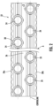
FIG. 2 is a plan view of a plate fin of the round tube plate fin heat exchanger coil ofFIG. 1 ; -
FIG. 3 is a perspective sectional view of an exemplary contoured region of the plate fin; -
FIG. 4 is a cross-sectional view of the contoured region ofFIG. 3 ; and -
FIG. 5 is a cross-sectional view of another contoured region of a plate fin. - A detailed description of one or more embodiments of the disclosed apparatus and method are presented herein by way of exemplification and not limitation with reference to the Figures. With reference to the accompanying drawings, like elements are numbered alike.
- Referring to
FIG. 1 , an exemplary plate finned tubeheat exchanger coil 20 is illustrated. As shown, theheat exchanger coil 20 includes at least oneplate fin 22, such as a plurality of plate fins for example. Eachplate fin 22 has one ormore holes 24 formed therein for receiving one ormore tubes 26 of theheat exchanger coil 20. The plurality ofplate fins 22 are maintained together by oppositely positionedtube sheets 28 havingholes 30 therethrough in axially alignment withtube holes 24. The plurality oftubes 26 are laced through theholes plate fins 22 and thetube sheets 28 and have their open ends joined together in fluid communication by u-shapedreturn bends 32, which are secured to thetubes 26 by soldering, brazing or the like. In an embodiment, there is no interference between thetubes 26 and thetube sheets 28; rather, thetubes 26 are only arranged in contact with theplate fins 22. - In operation, a first fluid to be cooled or heated flows through the
tubes 26 and a second cooling or heating fluid is then passed betweenfin sheets 22 and over an exterior surface of thetubes 26 in a direction indicated by arrow A. Heat energy is transferred from or to the first fluid through thetubes 26 and theplate fins 22 to or from the other fluid. The fluids may be different types, for example, the fluid flowing throughtubes 26 can be a refrigerant and the fluid flowing betweenplate fins 22 and over thetubes 26 can be air. However, embodiments where the fluids are the same type of fluid are also contemplated herein. - In the illustrated, non-limiting embodiment of
FIG. 1 , the plate fin tubeheat exchanger coil 20 is a staggered two-row coil since eachplate fin 22 has two rows of staggered holes therein for receiving tubes. However, it should be understood that a plate fin tubeheat exchanger coil 20 having any number of rows of tubes, such as only a single row of tubes, or more than two rows of tubes, and also a plate fin tubeheat exchanger coil 20 where theholes 24 for receiving the tubes are staggered or aligned with theholes 24 of an adjacent row are within the scope of the invention. - With reference to
FIG. 2 , anexemplary plate fin 22 is illustrated in more detail. As shown, the plurality ofholes 24 are arranged in one or more rows, with all the holes in a given row having a common centerline that is oriented parallel tofin edges tube holes 24 is an inter-row area 36. In an embodiment, afin collar 38 surrounds eachtube hole 24. Thefin collar 38 is configured to extend outwardly from a surface ofplate fin 22 in a first direction. By the length to which they extend from the surface of thefin 22, the plurality offin collars 38 serve to determine the spacing between the plurality ofplate fins 22 in a givenheat exchanger coil 20. The plurality offin collars 38 may also function to ensure that there is a sufficient area of contact and a close mechanical fit, and therefore good thermal conduction, between theplate fins 22 and thetubes 26. -
FIG. 3 is a perspective view of a cross-section of theplate fin 22 ofFIG. 2 taken in a plane (line 3-3) oriented generally transverse to theplate fin 22. As shown, theplate fin 22 includes a contouredregion 40 disposed betweenadjacent holes 24 in the same row. The contouredregion 40 may include a sinusoidal corrugation or sine-like waveform that runs parallel to the direction of the air flow A and perpendicular to theedges plate fin 22. As used herein the term "sinusoidal" is intended to cover waveforms or patterns that may be either true sine curves or approximations of a sine curve. Further, it should be understood that term "sinusoidal corrugation" may additionally include waveforms that represent a sine wave with a phase shift, for example resulting in a cosine-like waveform. Design requirements and practical considerations inherent in preparing tooling and in manufacturing thefins 22 mean that the waveforms may not necessarily be mathematically precise sine curves. - In the illustrated, non-limiting embodiment of
FIG. 3 , the contouredregion 40 includes a sinusoidal corrugation extending two wave counts in the flow direction, A. Accordingly, the sinusoidal corrugation has two peaks and two valleys associated therewith. However, embodiments having a contouredregion 40 including a sinusoidal corrugation extending less than two wave counts, such as a single wave count or 1.5 wave count, or alternatively, more than two wave counts are also contemplated herein. For example, in the non-limiting embodiment ofFIGS. 4 and5 , the sinusoidal corrugation extends about 2.5 wave counts. Each wave of the wave count has a respective wavelength L. Further, although the wavelength L of each wave within the wave count is illustrated as being generally equal, embodiments where the wavelengths may vary in the direction of the airflow are also contemplated herein. - In an embodiment, the sinusoidal corrugations including at least one peak and at least one valley located at the contoured
region 40 of theplate fin 22 do not have a continuous surface. Rather, at least oneelongate lance element 44 is created and defined bylongitudinal slits 42. In the illustrated, non-limiting embodiment ofFIG. 3 , the sixlongitudinal slits 42 in the contouredregion 40 of theplate fin 22 form a total of sevenlance elements 44. In another embodiment, as illustrated inFIGS. 4 and5 , the contouredregion 40 includes elevenlance elements 44. Accordingly, it should be understood that a contouredregion 40 having any suitable number of lance elements, such as five lance elements, six lance elements, eight lance elements, nine lance elements, ten lance elements, twelve lance elements, or thirteen lance elements for example, are within the scope of the invention. - Although the
slits 42 are illustrated as extending perpendicular to the direction of the air flow A, or parallel to theedges plate fin 22, embodiments where one or more of theslits 42 is arranged at an angle to anedges plate fin 22 are also within the scope of the invention. In an embodiment, thelance elements 44 are only located at a portion of the sinusoidal corrugation axially aligned with a portion of thetube hole 24. Accordingly, a trough formed between adjacent tube rows, such as within inter-row area 36 for example, does not have anylance elements 44 formed therein. - As shown in
FIGS. 3-5 , afirst portion 46 of thelance elements 44 are fixed in place along the curvature of the sinusoidal corrugation. These lance elements also referred to herein as "fixed lance elements." Thesecond portion 48 of thelance elements 44 are moved, for example translated, after formation thereof, such as relative to the mean line of the sinusoidal corrugation, illustrated as the central plane P (seeFIGS. 4 and5 ). Thelance elements 48 that have an adjusted position may also be referred to herein as "adjusted lance elements." In the embodiment shown inFIG. 3 , the sinusoidal corrugation includes four fixedlance elements 46 and three adjustedlance elements 48. In the non-limiting embodiment ofFIGS. 4 and5 , the sinusoidal corrugation includes six fixedlance elements 46 and fiveadjustable lance elements 48. - In an embodiment, the plurality of
lance elements 44 maintain the curvature of the sinusoidal corrugation. Said another way, each of the plurality ofelongate lance elements 44 has a cross-sectional shape that is a segment of the sinusoidal corrugation. The adjustableelongate lance elements 48 may be cut or lanced such that theslits 42 defining theadjustable lance elements 48 are disposed on opposite sides of the peaks and troughs of the sinusoidal corrugation. Accordingly, anadjustable lance element 48 arranged at a peak of the sinusoidal corrugation has a generally concave curvature and anadjustable lance element 48 arranged at a valley of the sinusoidal configuration has a generally convex curvature. In such embodiments, the wave count over which the sinusoidal corrugation extends will at least partially determine the total number oflance elements 44 included. Although theadjustable lance elements 48 are illustrated as being positioned at the peaks and troughs respectively, of the sinusoidal corrugations, it should be understood that anadjustable lance element 48 may be formed at any position along the sinusoidal corrugations. - With reference now to
FIGS. 4 and5 , an end view of a contouredregion 40 of theplate fin 22 is illustrated. As shown, the horizontal central plane P extends generally through the sinusoidal corrugation at a midpoint of the amplitude or height of the waveform. Accordingly, the distance between the plane P and a peak of the sinusoidal corrugation is equal to a distance between the plane P and a valley of the sinusoidal corrugation. In an embodiment, the at least oneadjusted lance element 48 may be offset from the sinusoidal corrugation by a distance referred to as lance offset as exemplified inFIGS. 4 and5 . - As shown in
FIG. 4 , in an embodiment, at least one of the adjustedlance elements 44 is moved in a downward direction, beyond alower surface 46 of theplate fin 22. In an embodiment, this downward direction is a second direction, opposite the first direction in which thefin collar 38 extends from theplate fin 22. As shown, each of the adjustedlance elements 48a originated from a valley of the sinusoidal corrugation is moved downwardly away from plane P, such that an upper surface of thelance element 48a is positioned vertically beneath alower surface 50 of theplate fin 22. As a result of this movement, the distance between thelance element 48a and the plane P increases. Each of thelance elements 48b originated from a peak of the sinusoidal corrugation may be similarly moved in the same second, downward direction such that an upper surface of thelance element 48b is positioned vertically beneath thelower surface 50 of theplate fin 22. However, the downward movement moves thelance elements 48b towards the plane P such that the distance between thelance elements 48b and the plane P decreases. Accordingly, the distance between the plane P and the lance elements 44 a is different than the distance between the lance elements 44b and the plane P. In an embodiment, the distance by which the lance elements 44a and the lance elements 44b are offset from the sinusoidal corrugation, in a direction perpendicular to the direction of flow A, such as relative to the plane P for example, also referred to herein as the lance offset, may be uniform. - In another embodiment, best shown in
FIG. 5 , the at least onelance element 48a arranged at a valley of the sinusoidal corrugation is moved in an opposite direction as at least onelance element 48b arranged at a peak of the sinusoidal corrugation. As shown, each of the lance elements 44a arranged at a valley of the sinusoidal corrugation is moved in the second direction, downwardly away from plane P. As a result, an upper surface of thelance element 48a is positioned vertically beneath thelower surface 50 of theplate fin 22. Because of this movement, the distance between thelance element 48a and the plane P increases. Similarly, each of thelance elements 48b formed at a peak of the sinusoidal corrugation is moved in the first, upward direction in which thefin collar 38 extends from theplate fin 22. With this movement away from the plane P, the lower surface of thelance element 48b may be positioned vertically above theupper surface 52 of theplate fin 22. In an embodiment, the total distance that eachlance element - The term "about" is intended to include the degree of error associated with measurement of the particular quantity based upon the equipment available at the time of filing the application.
- The terminology used herein is for the purpose of describing particular embodiments only and is not intended to be limiting of the present invention. As used herein, the singular forms "a", "an" and "the" are intended to include the plural forms as well, unless the context clearly indicates otherwise. It will be further understood that the terms "comprises" and/or "comprising," when used in this specification, specify the presence of stated features, integers, steps, operations, elements, and/or components, but do not preclude the presence or addition of one or more other features, integers, steps, operations, element components, and/or groups thereof.
- While the present invention has been described with reference to an exemplary embodiment or embodiments, it will be understood by those skilled in the art that various changes may be made and equivalents may be substituted for elements thereof without departing from the scope of the present invention, as defined by the appended claims. In addition, many modifications may be made to adapt a particular situation or material to the teachings of the present invention without departing from the scope thereof. Therefore, it is intended that the present invention not be limited to the particular embodiment disclosed as the best mode contemplated for carrying out this present invention, but that the present invention will include all embodiments falling within the scope of the claims.
Claims (11)
- A heat exchanger (20) comprising a plurality of plate fins (22), at least one plate fin comprising:a plurality of holes (24) arranged in one or more rows; anda contoured region (40) formed adjacent one of the plurality of holes (24) having a sinusoidal corrugation, the contoured region (40) comprising a plurality of elongate adjustable lance elements (48a, 48b), wherein said plurality of elongate adjustable lance elements are lowered relative to a central plane (P) arranged at a midpoint of an amplitude of the sinusoidal corrugation.
- A heat exchanger (20) comprising a plurality of plate fins (22), at least one plate fin comprising:a plurality of holes (24) arranged in one or more rows; anda contoured region (40) arranged between adjacent holes (24) within one of the one or more rows and having a sinusoidal corrugation, the contoured region (40) comprising a plurality of elongate adjustable lance elements (48a, 48b), wherein each of said plurality of elongate adjustable lance elements are spaced a further distance from a central plane (P) arranged at a midpoint of an amplitude of the sinusoidal corrugation than the sinusoidal corrugation.
- The heat exchanger of claim 1, wherein the contoured region (40) is arranged between adjacent holes (24) within one of the one or more rows.
- The heat exchanger of any preceding claim, wherein the sinusoidal corrugation extends over at least one sinusoidal corrugation wavelength.
- The heat exchanger of claim 4, wherein the at least one sinusoidal corrugation wavelength comprises two sinusoidal corrugation wavelengths, and the two sinusoidal corrugation wavelengths are constant.
- The heat exchanger of claim 4, wherein the at least one sinusoidal corrugation wavelength comprises two sinusoidal corrugation wavelengths, and the two sinusoidal corrugation wavelengths vary.
- The heat exchanger of any preceding claim, wherein each of the plurality of elongate adjustable lance elements (48a, 48b) has a cross-section that is a segment of the sinusoidal corrugation.
- The heat exchanger of any preceding claim, wherein the sinusoidal corrugation comprises at least one peak and at least one valley, at least one elongate adjustable lance element (48a, 48b) of the plurality of elongate adjustable lance elements being formed at the at least one valley.
- The heat exchanger of claim 8, wherein the at least one elongate adjustable lance element (48a, 48b) of the plurality of elongate adjustable lance elements being formed at the at least one valley has a generally convex curvature.
- The heat exchanger of any preceding claim, wherein the sinusoidal corrugation comprises at least one peak and at least one valley, at least one elongate adjustable lance element (48a, 48b) of the plurality of elongate lance elements being formed at the at least one peak.
- The heat exchanger of claim 10, wherein the at least one elongate adjustable lance element (48a, 48b) of the plurality of elongate adjustable lance elements being formed at the at least one peak has a generally concave curvature.
Applications Claiming Priority (1)
| Application Number | Priority Date | Filing Date | Title |
|---|---|---|---|
| US202263319980P | 2022-03-15 | 2022-03-15 |
Publications (1)
| Publication Number | Publication Date |
|---|---|
| EP4246081A1 true EP4246081A1 (en) | 2023-09-20 |
Family
ID=85640667
Family Applications (1)
| Application Number | Title | Priority Date | Filing Date |
|---|---|---|---|
| EP23161925.5A Pending EP4246081A1 (en) | 2022-03-15 | 2023-03-14 | High performance lanced sine wave fin configuration |
Country Status (3)
| Country | Link |
|---|---|
| US (1) | US12529530B2 (en) |
| EP (1) | EP4246081A1 (en) |
| CN (1) | CN116772640A (en) |
Families Citing this family (2)
| Publication number | Priority date | Publication date | Assignee | Title |
|---|---|---|---|---|
| CN116772640A (en) * | 2022-03-15 | 2023-09-19 | 开利公司 | High performance sawtooth sine wave fin structure |
| US20250155202A1 (en) * | 2023-11-10 | 2025-05-15 | Carrier Corporation | Lanced sine wave fin configuration for heat exchangers |
Citations (4)
| Publication number | Priority date | Publication date | Assignee | Title |
|---|---|---|---|---|
| US5111876A (en) * | 1991-10-31 | 1992-05-12 | Carrier Corporation | Heat exchanger plate fin |
| US5168923A (en) * | 1991-11-07 | 1992-12-08 | Carrier Corporation | Method of manufacturing a heat exchanger plate fin and fin so manufactured |
| US20060005956A1 (en) * | 2001-06-28 | 2006-01-12 | York International Corporation | High-V plate fin heat exchanger and method of manufacturing |
| US20180306533A1 (en) * | 2015-10-23 | 2018-10-25 | Carrier Corporation | Hydrophobic heat exchangers |
Family Cites Families (69)
| Publication number | Priority date | Publication date | Assignee | Title |
|---|---|---|---|---|
| US3645330A (en) * | 1970-02-05 | 1972-02-29 | Mcquay Inc | Fin for a reversible heat exchanger |
| US3796258A (en) * | 1972-10-02 | 1974-03-12 | Dunham Bush Inc | High capacity finned tube heat exchanger |
| JPS5926237B2 (en) * | 1978-06-21 | 1984-06-25 | 株式会社日立製作所 | Heat exchanger |
| JPS55105194A (en) * | 1979-02-07 | 1980-08-12 | Hitachi Ltd | Heat-exchanger |
| US4434844A (en) * | 1981-05-15 | 1984-03-06 | Daikin Kogyo Co., Ltd. | Cross-fin coil type heat exchanger |
| JP2730908B2 (en) * | 1988-06-09 | 1998-03-25 | 三洋電機株式会社 | Heat exchanger and air conditioner incorporating this heat exchanger |
| JPH0610591B2 (en) * | 1983-07-29 | 1994-02-09 | 三菱電機株式会社 | Heat exchanger |
| US5042576A (en) * | 1983-11-04 | 1991-08-27 | Heatcraft Inc. | Louvered fin heat exchanger |
| US4691768A (en) * | 1985-12-27 | 1987-09-08 | Heil-Quaker Corporation | Lanced fin condenser for central air conditioner |
| US4705105A (en) * | 1986-05-06 | 1987-11-10 | Whirlpool Corporation | Locally inverted fin for an air conditioner |
| US4723599A (en) * | 1987-03-06 | 1988-02-09 | Lennox Industries, Inc. | Lanced fin heat exchanger |
| US4860822A (en) * | 1987-12-02 | 1989-08-29 | Carrier Corporation | Lanced sine-wave heat exchanger |
| US4817709A (en) * | 1987-12-02 | 1989-04-04 | Carrier Corporation | Ramp wing enhanced plate fin |
| US5353866A (en) * | 1987-12-04 | 1994-10-11 | Hitachi, Ltd. | Heat transfer fins and heat exchanger |
| CA1316528C (en) | 1988-01-11 | 1993-04-20 | Paul H. Ballentine | Suction enhancement for a wavy plate-fin |
| US5062475A (en) * | 1989-10-02 | 1991-11-05 | Sundstrand Heat Transfer, Inc. | Chevron lanced fin design with unequal leg lengths for a heat exchanger |
| US4984626A (en) * | 1989-11-24 | 1991-01-15 | Carrier Corporation | Embossed vortex generator enhanced plate fin |
| US5099914A (en) * | 1989-12-08 | 1992-03-31 | Nordyne, Inc. | Louvered heat exchanger fin stock |
| US5056594A (en) * | 1990-08-03 | 1991-10-15 | American Standard Inc. | Wavy heat transfer surface |
| JP2661356B2 (en) * | 1990-10-22 | 1997-10-08 | 松下電器産業株式会社 | Finned heat exchanger |
| US5360060A (en) * | 1992-12-08 | 1994-11-01 | Hitachi, Ltd. | Fin-tube type heat exchanger |
| US5509469A (en) * | 1994-04-19 | 1996-04-23 | Inter-City Products Corporation (Usa) | Interrupted fin for heat exchanger |
| KR0128678B1 (en) * | 1994-07-21 | 1998-04-04 | 김광호 | Air-condition machinery of heat exchanger |
| US5722485A (en) * | 1994-11-17 | 1998-03-03 | Lennox Industries Inc. | Louvered fin heat exchanger |
| KR0179540B1 (en) * | 1995-01-23 | 1999-04-15 | 구자홍 | Plate Fins for Finned Tube Heat Exchangers |
| TW340180B (en) | 1995-09-14 | 1998-09-11 | Sanyo Electric Co | Heat exchanger having corrugated fins and air conditioner having the same |
| US5660230A (en) * | 1995-09-27 | 1997-08-26 | Inter-City Products Corporation (Usa) | Heat exchanger fin with efficient material utilization |
| US5738168A (en) * | 1995-12-08 | 1998-04-14 | Ford Motor Company | Fin tube heat exchanger |
| KR100202061B1 (en) * | 1995-12-28 | 1999-06-15 | 전주범 | Heat excahger fin for air conditioner |
| US5752567A (en) * | 1996-12-04 | 1998-05-19 | York International Corporation | Heat exchanger fin structure |
| US5927393A (en) * | 1997-12-11 | 1999-07-27 | Heatcraft Inc. | Heat exchanger fin with enhanced corrugations |
| IT1318156B1 (en) * | 2000-02-29 | 2003-07-23 | Sanyo Electric C Ltd | Heat exchanger for air-conditioner, consists of heat transfer fin with slit, and width of slit, width of fin and number of fin rows satisfy specific relationship |
| WO2001075386A1 (en) | 2000-03-31 | 2001-10-11 | York International Corporation | Dual fin enhancements and a method of making |
| US20030150601A1 (en) * | 2002-02-08 | 2003-08-14 | Mando Climate Control Corporation | Heat exchanger fin for air conditioner |
| US6786274B2 (en) * | 2002-09-12 | 2004-09-07 | York International Corporation | Heat exchanger fin having canted lances |
| US7261147B2 (en) * | 2003-05-28 | 2007-08-28 | Lg Electronics Inc. | Heat exchanger |
| CA2431732A1 (en) * | 2003-06-11 | 2004-12-11 | Dana Canada Corporation | Method and apparatus for forming a turbulizer |
| KR100543599B1 (en) * | 2003-09-15 | 2006-01-20 | 엘지전자 주식회사 | heat transmitter |
| AU2003269188A1 (en) * | 2003-09-19 | 2005-04-11 | Ti Group Automotive Systems Limited | Heat exchanger cooling fin |
| JP4626422B2 (en) | 2005-07-01 | 2011-02-09 | ダイキン工業株式会社 | Finned tube heat exchanger |
| US10415894B2 (en) * | 2006-01-26 | 2019-09-17 | Ingersoll-Rand Company | Fin and tube heat exchanger |
| WO2007091561A1 (en) * | 2006-02-06 | 2007-08-16 | Matsushita Electric Industrial Co., Ltd. | Fin-tube heat exchanger |
| JP4028591B2 (en) | 2006-04-21 | 2007-12-26 | 松下電器産業株式会社 | Heat transfer fin and fin tube heat exchanger |
| FR2902505B1 (en) | 2006-06-19 | 2008-08-29 | Valeo Systemes Thermiques | THREAD WITH IMPROVED FLOW DEFLECTOR AND HEAT EXCHANGER PROVIDED WITH SUCH AILT |
| US7721794B2 (en) * | 2007-02-09 | 2010-05-25 | Lennox Industries Inc. | Fin structure for heat exchanger |
| JP5417718B2 (en) | 2007-03-07 | 2014-02-19 | ダイキン工業株式会社 | Heat exchanger |
| US8267160B2 (en) * | 2009-08-11 | 2012-09-18 | Trane International Inc. | Louvered plate fin |
| US20120227945A1 (en) * | 2009-09-16 | 2012-09-13 | Carrier Corporation | Free-draining finned surface architecture for heat exchanger |
| CN102472599B (en) * | 2009-09-16 | 2014-02-19 | 松下电器产业株式会社 | Fin tube heat exchanger |
| KR20110055839A (en) * | 2009-11-20 | 2011-05-26 | 삼성전자주식회사 | Heat exchanger and air conditioner having same |
| KR20110083017A (en) * | 2010-01-13 | 2011-07-20 | 엘지전자 주식회사 | Fins for heat exchanger and heat exchanger with same |
| JP5958771B2 (en) | 2011-10-11 | 2016-08-02 | パナソニックIpマネジメント株式会社 | Finned tube heat exchanger |
| CN103874901B (en) | 2011-10-14 | 2015-12-23 | 松下电器产业株式会社 | Finned tube heat exchanger |
| JP5958744B2 (en) | 2012-04-16 | 2016-08-02 | パナソニックIpマネジメント株式会社 | Finned tube heat exchanger |
| KR101936224B1 (en) * | 2012-04-26 | 2019-01-08 | 엘지전자 주식회사 | A heat exchanger |
| KR101882020B1 (en) * | 2012-08-01 | 2018-07-25 | 엘지전자 주식회사 | A heat exchanger |
| KR20140017835A (en) * | 2012-08-01 | 2014-02-12 | 엘지전자 주식회사 | A heat exchanger |
| WO2014138952A1 (en) * | 2013-03-15 | 2014-09-18 | Dana Canada Corporation | Heat transfer surface with nested tabs |
| US9644896B2 (en) * | 2013-04-12 | 2017-05-09 | Panasonic Intellectual Property Management Co., Ltd. | Fin-and-tube heat exchanger and refrigeration cycle device |
| US10209012B2 (en) * | 2015-02-24 | 2019-02-19 | Lgl France | Heat exchanger with louvered fins |
| JP6289729B2 (en) * | 2015-03-02 | 2018-03-07 | 三菱電機株式会社 | Fin-and-tube heat exchanger and refrigeration cycle apparatus provided with the same |
| USD800282S1 (en) * | 2016-03-03 | 2017-10-17 | Lennox Industries Inc. | Heat exchanger fin |
| US10801784B2 (en) * | 2016-04-13 | 2020-10-13 | Daikin Industries, Ltd. | Heat exchanger with air flow passage for exchanging heat |
| CN110081764B (en) | 2018-01-25 | 2021-09-28 | 浙江盾安热工科技有限公司 | Heat exchanger fin and heat exchanger thereof |
| CA3036460A1 (en) * | 2018-03-14 | 2019-09-14 | Rheem Manufacturing Company | Heat exchanger fin |
| US11326842B2 (en) * | 2018-09-21 | 2022-05-10 | Samsung Electronics Co., Ltd. | Heat exchanger and air conditioner having the same |
| US11519679B2 (en) * | 2019-09-05 | 2022-12-06 | Carrier Corporation | Vortex-enhanced heat exchanger |
| CN116772640A (en) * | 2022-03-15 | 2023-09-19 | 开利公司 | High performance sawtooth sine wave fin structure |
| US20250155202A1 (en) * | 2023-11-10 | 2025-05-15 | Carrier Corporation | Lanced sine wave fin configuration for heat exchangers |
-
2023
- 2023-03-13 CN CN202310235654.1A patent/CN116772640A/en active Pending
- 2023-03-14 EP EP23161925.5A patent/EP4246081A1/en active Pending
- 2023-03-15 US US18/184,124 patent/US12529530B2/en active Active
Patent Citations (4)
| Publication number | Priority date | Publication date | Assignee | Title |
|---|---|---|---|---|
| US5111876A (en) * | 1991-10-31 | 1992-05-12 | Carrier Corporation | Heat exchanger plate fin |
| US5168923A (en) * | 1991-11-07 | 1992-12-08 | Carrier Corporation | Method of manufacturing a heat exchanger plate fin and fin so manufactured |
| US20060005956A1 (en) * | 2001-06-28 | 2006-01-12 | York International Corporation | High-V plate fin heat exchanger and method of manufacturing |
| US20180306533A1 (en) * | 2015-10-23 | 2018-10-25 | Carrier Corporation | Hydrophobic heat exchangers |
Also Published As
| Publication number | Publication date |
|---|---|
| CN116772640A (en) | 2023-09-19 |
| US20230296329A1 (en) | 2023-09-21 |
| US12529530B2 (en) | 2026-01-20 |
Similar Documents
| Publication | Publication Date | Title |
|---|---|---|
| EP0319451B1 (en) | Lanced sine-wave heat exchanger | |
| US12529530B2 (en) | High performance lanced sine wave fin configuration | |
| US5111876A (en) | Heat exchanger plate fin | |
| US8516699B2 (en) | Method of manufacturing a heat exchanger having a contoured insert | |
| US5318112A (en) | Finned-duct heat exchanger | |
| US5722485A (en) | Louvered fin heat exchanger | |
| US20130277029A1 (en) | Heat Transfer Surfaces With Flanged Apertures | |
| US4305457A (en) | High density fin material | |
| US20030178188A1 (en) | Micro-channel heat exchanger | |
| US20130240177A1 (en) | Nested heat exchanger | |
| JPH0238232Y2 (en) | ||
| US20250155202A1 (en) | Lanced sine wave fin configuration for heat exchangers | |
| WO2013161290A1 (en) | Finned tube heat exchanger | |
| CN109470075B (en) | Fins and heat exchangers | |
| CA1069883A (en) | Compact primary surface heat exchanger | |
| KR20110083016A (en) | Fins for heat exchanger and heat exchanger with same | |
| EP1007893B1 (en) | Heat exchanger turbulizers with interrupted convolutions | |
| US5476140A (en) | Alternately staggered louvered heat exchanger fin | |
| EP2663825B1 (en) | Heat exchanger | |
| EP3399271B1 (en) | Heat exchanger | |
| EP2064509B1 (en) | Heat transfer surfaces with flanged apertures | |
| RU117595U1 (en) | HEAT EXCHANGE DEVICE | |
| SU1746193A1 (en) | Heat exchange surface | |
| AU598965B2 (en) | Improved heat exchanger fins | |
| WO2013161239A1 (en) | Finned tube heat exchanger |
Legal Events
| Date | Code | Title | Description |
|---|---|---|---|
| PUAI | Public reference made under article 153(3) epc to a published international application that has entered the european phase |
Free format text: ORIGINAL CODE: 0009012 |
|
| STAA | Information on the status of an ep patent application or granted ep patent |
Free format text: STATUS: THE APPLICATION HAS BEEN PUBLISHED |
|
| AK | Designated contracting states |
Kind code of ref document: A1 Designated state(s): AL AT BE BG CH CY CZ DE DK EE ES FI FR GB GR HR HU IE IS IT LI LT LU LV MC ME MK MT NL NO PL PT RO RS SE SI SK SM TR |
|
| STAA | Information on the status of an ep patent application or granted ep patent |
Free format text: STATUS: REQUEST FOR EXAMINATION WAS MADE |
|
| 17P | Request for examination filed |
Effective date: 20240320 |
|
| RBV | Designated contracting states (corrected) |
Designated state(s): AL AT BE BG CH CY CZ DE DK EE ES FI FR GB GR HR HU IE IS IT LI LT LU LV MC ME MK MT NL NO PL PT RO RS SE SI SK SM TR |
|
| STAA | Information on the status of an ep patent application or granted ep patent |
Free format text: STATUS: EXAMINATION IS IN PROGRESS |
|
| 17Q | First examination report despatched |
Effective date: 20241202 |