EP4246069A1 - Slide mechanism for a built-in refrigerator - Google Patents
Slide mechanism for a built-in refrigerator Download PDFInfo
- Publication number
- EP4246069A1 EP4246069A1 EP23154801.7A EP23154801A EP4246069A1 EP 4246069 A1 EP4246069 A1 EP 4246069A1 EP 23154801 A EP23154801 A EP 23154801A EP 4246069 A1 EP4246069 A1 EP 4246069A1
- Authority
- EP
- European Patent Office
- Prior art keywords
- sliding
- rail
- cover
- rail element
- sliding element
- Prior art date
- Legal status (The legal status is an assumption and is not a legal conclusion. Google has not performed a legal analysis and makes no representation as to the accuracy of the status listed.)
- Granted
Links
Images



Classifications
-
- F—MECHANICAL ENGINEERING; LIGHTING; HEATING; WEAPONS; BLASTING
- F25—REFRIGERATION OR COOLING; COMBINED HEATING AND REFRIGERATION SYSTEMS; HEAT PUMP SYSTEMS; MANUFACTURE OR STORAGE OF ICE; LIQUEFACTION SOLIDIFICATION OF GASES
- F25D—REFRIGERATORS; COLD ROOMS; ICE-BOXES; COOLING OR FREEZING APPARATUS NOT OTHERWISE PROVIDED FOR
- F25D23/00—General constructional features
- F25D23/02—Doors; Covers
- F25D23/021—Sliding doors
-
- F—MECHANICAL ENGINEERING; LIGHTING; HEATING; WEAPONS; BLASTING
- F25—REFRIGERATION OR COOLING; COMBINED HEATING AND REFRIGERATION SYSTEMS; HEAT PUMP SYSTEMS; MANUFACTURE OR STORAGE OF ICE; LIQUEFACTION SOLIDIFICATION OF GASES
- F25D—REFRIGERATORS; COLD ROOMS; ICE-BOXES; COOLING OR FREEZING APPARATUS NOT OTHERWISE PROVIDED FOR
- F25D23/00—General constructional features
- F25D23/02—Doors; Covers
- F25D23/028—Details
-
- A—HUMAN NECESSITIES
- A47—FURNITURE; DOMESTIC ARTICLES OR APPLIANCES; COFFEE MILLS; SPICE MILLS; SUCTION CLEANERS IN GENERAL
- A47B—TABLES; DESKS; OFFICE FURNITURE; CABINETS; DRAWERS; GENERAL DETAILS OF FURNITURE
- A47B77/00—Kitchen cabinets
- A47B77/04—Provision for particular uses of compartments or other parts ; Compartments moving up and down, revolving parts
- A47B77/08—Provision for particular uses of compartments or other parts ; Compartments moving up and down, revolving parts for incorporating apparatus operated by power, including water power; for incorporating apparatus for cooking, cooling, or laundry purposes
-
- F—MECHANICAL ENGINEERING; LIGHTING; HEATING; WEAPONS; BLASTING
- F25—REFRIGERATION OR COOLING; COMBINED HEATING AND REFRIGERATION SYSTEMS; HEAT PUMP SYSTEMS; MANUFACTURE OR STORAGE OF ICE; LIQUEFACTION SOLIDIFICATION OF GASES
- F25D—REFRIGERATORS; COLD ROOMS; ICE-BOXES; COOLING OR FREEZING APPARATUS NOT OTHERWISE PROVIDED FOR
- F25D23/00—General constructional features
- F25D23/10—Arrangements for mounting in particular locations, e.g. for built-in type, for corner type
Definitions
- the present disclosure relates to built-in appliances, such as a refrigerator, that are installed within a piece of furniture, such as a cabinet structure.
- Appliances such as refrigerators, may be installed inside of pieces of furniture, such as cabinet structures.
- a sliding and connecting device configured for slidably connecting a refrigerator appliance door to a cabinet panel includes a sliding element, a rail element, and a removable portion.
- the sliding element defines a channel, is configured to be mounted to one of the refrigerator appliance door or the cabinet panel, and defines at least one first orifice configured to receive fasteners for mounting the sliding element.
- the rail element is separated from the sliding element, is configured for disposal within the channel such that rail element engages the sliding element and is slidable within the channel, is configured to be mounted to the other of the refrigerator appliance door or the cabinet panel, and defines at least one second orifice configured to receive fasteners for mounting the sliding element.
- the removable portion is secured to a first of the sliding element or rail element.
- the removeable portion includes at least one cover and at least one bridge securing the at least one cover to the first of the sliding element or rail element.
- the removable portion is configured to engage an edge of the refrigerator appliance door or an edge of the cabinet panel for aligning the first of the sliding element or rail element relative to the refrigerator appliance door for installation of the first of the sliding element or rail element onto the cabinet panel.
- the removable portion is configured for removal from the first of the sliding element or rail element after installation of the first of the sliding element or rail element onto the cabinet panel.
- the at least one cover is configured to be secured to the sliding element or to the rail element for disposal over the at least one first orifice or the at least one second orifice, respectively, upon removal of the at least one cover from the first of the sliding element or rail element.
- the first of the sliding element or rail element is the rail element
- the at least one cover includes a rail element cover and a sliding element cover
- the at least one bridge includes a first bridge securing the rail element cover to the rail element and a second bridge securing the sliding element cover to the rail element cover.
- the rail element is configured for installation onto the cabinet panel and (ii) an outer edge of the sliding element cover is configured to align with and engage a side edge of a cabinet door to align the rail element relative to the refrigerator appliance door in a first direction prior to installation of the rail element onto the cabinet panel.
- an upper edge of the first bridge is configured to align with and engage a lower edge of a door bushing on the refrigerator appliance door to align the rail element relative to the refrigerator appliance door in a second direction prior to installation of the rail element onto the cabinet panel.
- the rail element cover includes clips configured to engage the rail element to secure the rail element cover to the rail element and over the at least one second orifice.
- the sliding element cover includes clips configured to engage the sliding element to secure the rail element cover to the sliding element and over the at least one first orifice.
- the first of the sliding element or rail element is the sliding element
- the at least one cover includes a rail element end cover
- the at least one bridge includes first and second bridges securing the rail element end cover to the rail element.
- the removable portion further comprises a gate extending outward from each of and spanning the first and second bridges.
- the gate is substantially perpendicular to the first and second bridges.
- the sliding element is configured for installation onto the cabinet panel and (ii) the gate is configured to align with and engage a side edge of the refrigerator appliance door to align the sliding element relative to the refrigerator appliance door prior to installation of the sliding element onto the cabinet panel.
- the rail element is configured for installation onto the refrigerator appliance door.
- the rail element end cover includes clips configured to engage the rail element to secure the rail element end cover to the rail element and over the at least one second orifice.
- a method for installation of a sliding and connecting device having a rail element and a sliding element to a refrigerator appliance door and a cabinet panel includes (i) integrating the rail element, a rail element cover, and a sliding element cover into a single component; (ii) positioning the rail element in a first direction by aligning an edge of the sliding element cover with a side edge of the cabinet panel; (iii) securing the rail element to the cabinet panel while the edge of the sliding element cover is aligned with the side edge of the cabinet panel; (iv) engaging the sliding element with the rail element; and (v) securing the sliding element to an edge of the refrigerator appliance door.
- the method further comprises positioning the rail element in a second direction prior to securing the rail to the cabinet panel by aligning an upper edge of a bridge, which secures the rail element cover to the rail element, with a lower edge of a door bushing on the refrigerator appliance door.
- the method further comprises (i) detaching the rail element cover from the rail element via severing a bridge that connects the rail element cover to the rail element and (ii) reattaching the rail element cover to the rail element via clips.
- the method further comprises (i) detaching the sliding element cover from the rail element via severing a bridge that connects the sliding element to the rail element cover and (ii) attaching the sliding element cover to the sliding element via clips.
- a method for installation of a sliding and connecting device having a rail element and a sliding element to a refrigerator appliance door and a cabinet panel includes (i) integrating the sliding element, a rail element cover, bridges extending between the sliding element and rail element cover, and a gate extending between the bridges into a single component; (ii) positioning the sliding element relative to the cabinet panel by aligning the gate with protrusions extending outward from an edge of the refrigerator appliance door; (iii) securing the sliding element to the cabinet panel while positioned relative to the cabinet panel; (iv) engaging the rail element with the sliding element; and (v) securing the rail element to the edge of the refrigerator appliance door.
- the method further comprises detaching the rail element cover from the sliding element via severing the bridges.
- the method further comprises attaching the rail element cover to the rail element via clips.
- the method of claim further comprises detaching the sliding element from the bridges and gate via severing the bridges.
- substantially or “about” may be used herein to describe disclosed or claimed embodiments.
- the term “substantially” or “about” may modify a value or relative characteristic disclosed or claimed in the present disclosure. In such instances, “substantially” or “about” may signify that the value or relative characteristic it modifies is within ⁇ 0%, 0.1%, 0.5%, 1%, 2%, 3%, 4%, 5% or 10% of the value or relative characteristic.
- first, second, third, etc. may be used to describe various elements, components, regions, layers and/or sections, these elements, components, regions, layers and/or sections should not be limited by these terms. These terms may be only used to distinguish one element, component, region, layer or section from another region, layer or section. Terms such as “first,” “second,” and other numerical terms when used herein do not imply a sequence or order unless clearly indicated by the context. Thus, a first element, component, region, layer or section discussed below could be termed a second element, component, region, layer or section without departing from the teachings of the example embodiments.
- spatially relative terms such as “inner,” “outer,” “beneath,” “below,” “lower,” “above,” “upper,” and the like, may be used for ease of description to describe one element or feature's relationship to another element(s) or feature(s) as illustrated in the figures. Spatially relative terms may be intended to encompass different orientations of the device in use or operation in addition to the orientation depicted in the figures. For example, if the device in the figures is turned over, elements described as “below” or “beneath” other elements or features would then be oriented “above” the other elements or features. Thus, the example term “below” can encompass both an orientation of above and below. The device may be otherwise oriented (rotated 90 degrees or at other orientations) and the spatially relative descriptors used herein interpreted accordingly.
- the present disclosure relates to a built-in appliance configured for installation in a piece of kitchen furniture having a front panel hinged to a cabinet structure.
- the front panel is typically arranged frontally at a door of the refrigerating appliance and connected thereto by way of at least a sliding and connecting device which comprises a rail element and a sliding element.
- the sliding and connecting device is installed between the door of the appliance and the front panel of a piece of furniture containing the household appliance, such panel being a door of the furniture niche.
- the two "doors”, i.e., the door of appliance and the panel/door of the piece of furniture, should remain as close to each other as possible during opening and closing, when there is a lateral shift between the two doors due to the two different vertical axis of hinges.
- the rail 10 may be configured to slide linearly within a C-shaped profile or channel defined by the sliding element 12.
- the rail defines orifices or openings 14 configured to receive fasteners for mounting the rail 10 to an interior surface of a panel or door of a piece of furniture, such as a cabinet.
- the sliding element 12 defines orifices or openings 16 configured to receive fasteners for mounting the sliding element 12 to an upper, lower, or side edge of a door of an appliance, such as a refrigerator, that is disposed within the piece of furniture, which may be a cabinet.
- the rail 10 may include a cover 18 that is disposed over the heads of the fasteners for aesthetic purposes once the rail 10 is secured the interior surface of the door of the piece of furniture.
- the cover 18 may include snaps, tabs, or clips 20 that engage notches or slots 22 defined by the rail 10 to secure the cover 18 to the rail 10.
- the rail 10 may define a pocket 24 and the cover 18 may be disposed within the pocket 24 upon installation such the cover 18 is flush with an exterior surface 26 of the rail 10, which may also be for aesthetic purposes.
- the sliding element 12 may also include a cover 28 that is disposed over the heads of the fasteners for aesthetic purposes once the sliding element 12 is secured the upper, lower, or side edge of the appliance door.
- the cover 28 may include snaps, tabs, or clips 30 that engage notches or slots 32 defined by the sliding element 12 to secure the cover 28 to the sliding element 12.
- the rail 10, cover 18, and cover 28 may be formed a single component during manufacturing. The positions of the covers 18, 28 relative to the rail 10 may be utilized for setting up the position of the rail 10 during installation and then removed from the rail 10 so that the covers 18, 28 may be installed onto the rail 10 and sliding element 12, respectively. For example, the covers 18, 28 may be removed from the rail 10 by cutting along dashed lines 34 before installation onto the rail 10 and sliding element 12, respectively.
- Bridges, bars, or arms 36 connecting the rail 10 to cover 18 may then be removed from cover 18 by cutting along dashed lines 35.
- One or more bridges, bars, or arms 36 connecting cover 28 to cover 18 may also have been removed when the cuts were made along dashed lines 34.
- FIGS. 3A-3H installation of the rail 10 onto a panel or door of a piece of furniture, such as a cabinet door 38, is illustrated under two scenarios.
- the rail 10 for either vertical set up (e.g., in first direction) according to Figure 3A (i.e., where the sliding element 12 is fastened (e.g., via fasteners 39, bolts, rivets, etc.) to an upper edge 40 of an appliance door 42) or a horizontal set up (e.g., in second direction) according to Figure 3B (i.e., where the sliding element 12 is fastened to a side edge 44 of the appliance door 42), the position of the rail 10 relative to a side edge 46 of the cabinet door 38 may be set by aligning the outer most edge 48 of the cover 28 with the side edge 46 of the cabinet door 38 (before the covers 18, 28 are removed from the rail 10) and fastening the rail 10 (e.g., via fasteners 39, bolts, rivets, etc.) to an interior surface 50 of the cabinet
- cover 18, cover 28, and arms 36 may all be removed from the rail 10 by cutting along lines 34, 35 (See Figures 1 and 3D ). Therefore, the cover 18, cover 28, and arms 36 may be collectively referred to as the removable portion.
- the rail 10 is positioned by installing the rail 10 immediately below a lower edge 52 of a door bushing 54 as illustrated by arrow 55 and securing the rail 10 to the interior surface 50 of the cabinet door 38 (See Figure 3C ) while the rail 10 is positioned immediately below the lower edge 52 of the door bushing 54. More specifically, an upper edge 56 of the upper arm 36 may be aligned with the lower edge 52 of door bushing 54 during a vertical set up.
- the snaps, tabs, or clips 20 on the cover 18 are inserted into and engage notches or slots 22 defined by the rail 10 to secure the cover 18 to the rail 10 (See Figures 3E ).
- the sliding element 12 is then slidably engaged with the rail 10 (See Figure 3F ).
- the sliding element 12 is then fastened (e.g., via fasteners, bolts, rivets, etc.) to either the upper edge 40 or side edge 44 of the appliance door 42 (See. Figure 3G ) depending on whether or a vertical set up or horizontal set up is being implemented.
- the snaps, tabs, or clips 30 on the cover 28 are inserted into and engage notches or slots 32 defined by the sliding element 12 to secure the cover 28 to the sliding element 12 (See. Figure 3H ).
- a rail 110 and a guiding element or sliding element 112 of a second embodiment of a rail mechanism or a sliding and connecting device are illustrated, respectively.
- the rail 110 may be configured to slide linearly within a C-shaped profile or channel defined by the sliding element 112.
- the rail defines orifices or openings 114 configured to receive fasteners for mounting the rail 110 to a side edge of a door of an appliance, such as a refrigerator, that is disposed within a piece of furniture, which may be a cabinet.
- the sliding element 112 defines orifices or openings 116 configured to receive fasteners for mounting the sliding element 112 to an interior surface of a panel or door of the piece of furniture.
- the rail 110 may include a cover 118 that is disposed over the heads of the fasteners for aesthetic purposes once the rail 110 is secured the side edge of the door of the appliance.
- the cover 118 may include snaps, tabs, or clips 120 that engage notches or slots 122 defined by the rail 110 to secure the cover 118 to the rail 110.
- the cover 118 may be referred to as the rail element end cover.
- the sliding element 112 and the cover 118 may be formed as a single component during manufacturing. More specifically, the sliding element 112 and the cover 118 may be formed as a single component via a pair of bridges, arms, or bars 124 that extend between the sliding element 112 and the cover 118.
- a loop or gate 126 that is utilized for positioning the sliding element 112 during installation extends between the bars 124.
- the gate 126 may be substantially perpendicular to the bars 124. Stated in other terms, the gate 126 may be C-shaped and may extend from the bars 124 in a direction that is substantially perpendicular to the direction that the bars 124 extend with respect to the sliding element 112 and cover 118. Substantially perpendicular may refer to any incremental value that ranges between exactly perpendicular and 15° from exactly perpendicular.
- the bars 124, the gate 126, and the cover 118 may be removed from the sliding element 112 once the sliding element 112 is installed onto the interior surface of the door of the piece of furniture. The removed cover 118 may then be installed onto the rail 110. More specifically, the bars 124, the gate 126, and the cover 118 may be removed from the sliding element 112 by cutting along dashed lines 128. The cover 118 is also removed from the bars 124 and the gate 126. Therefore, the bars 124, the gate 126, and the cover 118 may be collectively referred to as the removable portion.
- the installation includes eight steps. Steps 2-8 are labelled in Figures 6A-6F .
- the first step includes opening the cabinet door 130 and opening the door 132 of an appliance (e.g., a refrigerator) that is disposed within the piece of furniture (e.g., a cabinet). Both doors should be opened widely (e.g., as far as the doors will open until interference with adjacent components occurs or within 30° of as far as the doors will open).
- the gate 126 while still attached to the sliding element 112 is aligned with two protrusions 134 that extend outward from a side edge 136 of the appliance door 132 at step two.
- Aligning the gate 126 with the protrusions 134 places the sliding element 112 into a desired position on an interior surface 138 of the cabinet door 130.
- the appliance door 132 is then closed while the sliding element 112 is held in place in the desired position on the interior surface 138 of the cabinet door 130 at step three.
- the sliding element 112 is then fastened (e.g., via fasteners 39, bolts, rivets, etc.) to the interior surface 138 of the cabinet door 130 in the desired position at step four.
- the bars 124, the gate 126, and the cover 118 are removed from the sliding element 112 by cutting along dashed lines 128.
- the rail 110 is then inserted into the C-shaped profile or channel defined by the sliding element 112 at step six.
- the doors 130, 132 are transitioned to closed positions or to partially opened positions that are within a short range of the closed positions (e.g., within 30° of closed positions) and the rail 110 is fastened (e.g., via fasteners 39, bolts, rivets, etc.) to the side edge 136 of the appliance door 132.
- the cover 118 is secured to the end of the rail 110.
- first, second, third, fourth, etc. for any component, state, or condition described herein may be rearranged in the claims so that they are in chronological order with respect to the claims. Furthermore, it should be understood that any component, state, or condition described herein that does not have a numerical designation may be given a designation of first, second, third, fourth, etc. in the claims if one or more of the specific component, state, or condition are claimed.
Landscapes
- Engineering & Computer Science (AREA)
- Chemical & Material Sciences (AREA)
- Combustion & Propulsion (AREA)
- Physics & Mathematics (AREA)
- Mechanical Engineering (AREA)
- Thermal Sciences (AREA)
- General Engineering & Computer Science (AREA)
- Life Sciences & Earth Sciences (AREA)
- Sustainable Development (AREA)
- Refrigerator Housings (AREA)
Abstract
Description
- The present disclosure relates to built-in appliances, such as a refrigerator, that are installed within a piece of furniture, such as a cabinet structure.
- Appliances, such as refrigerators, may be installed inside of pieces of furniture, such as cabinet structures.
- A sliding and connecting device configured for slidably connecting a refrigerator appliance door to a cabinet panel includes a sliding element, a rail element, and a removable portion. The sliding element defines a channel, is configured to be mounted to one of the refrigerator appliance door or the cabinet panel, and defines at least one first orifice configured to receive fasteners for mounting the sliding element. The rail element is separated from the sliding element, is configured for disposal within the channel such that rail element engages the sliding element and is slidable within the channel, is configured to be mounted to the other of the refrigerator appliance door or the cabinet panel, and defines at least one second orifice configured to receive fasteners for mounting the sliding element. The removable portion is secured to a first of the sliding element or rail element. The removeable portion includes at least one cover and at least one bridge securing the at least one cover to the first of the sliding element or rail element. The removable portion is configured to engage an edge of the refrigerator appliance door or an edge of the cabinet panel for aligning the first of the sliding element or rail element relative to the refrigerator appliance door for installation of the first of the sliding element or rail element onto the cabinet panel. The removable portion is configured for removal from the first of the sliding element or rail element after installation of the first of the sliding element or rail element onto the cabinet panel. The at least one cover is configured to be secured to the sliding element or to the rail element for disposal over the at least one first orifice or the at least one second orifice, respectively, upon removal of the at least one cover from the first of the sliding element or rail element.
- In one or more embodiments, (i) the first of the sliding element or rail element is the rail element, (ii) the at least one cover includes a rail element cover and a sliding element cover, and (iii) the at least one bridge includes a first bridge securing the rail element cover to the rail element and a second bridge securing the sliding element cover to the rail element cover.
- According to some embodiments, (i) the rail element is configured for installation onto the cabinet panel and (ii) an outer edge of the sliding element cover is configured to align with and engage a side edge of a cabinet door to align the rail element relative to the refrigerator appliance door in a first direction prior to installation of the rail element onto the cabinet panel.
- According to at least one embodiment, an upper edge of the first bridge is configured to align with and engage a lower edge of a door bushing on the refrigerator appliance door to align the rail element relative to the refrigerator appliance door in a second direction prior to installation of the rail element onto the cabinet panel.
- In at least one embodiment, the rail element cover includes clips configured to engage the rail element to secure the rail element cover to the rail element and over the at least one second orifice.
- According to some embodiments, the sliding element cover includes clips configured to engage the sliding element to secure the rail element cover to the sliding element and over the at least one first orifice.
- According to at least one embodiment, (i) the first of the sliding element or rail element is the sliding element, (ii) the at least one cover includes a rail element end cover, (iii) the at least one bridge includes first and second bridges securing the rail element end cover to the rail element.
- In at least one embodiment, the removable portion further comprises a gate extending outward from each of and spanning the first and second bridges.
- In one or more embodiments, the gate is substantially perpendicular to the first and second bridges.
- In one or more embodiments, (i) the sliding element is configured for installation onto the cabinet panel and (ii) the gate is configured to align with and engage a side edge of the refrigerator appliance door to align the sliding element relative to the refrigerator appliance door prior to installation of the sliding element onto the cabinet panel.
- According to some embodiments, the rail element is configured for installation onto the refrigerator appliance door.
- In at least one embodiment, the rail element end cover includes clips configured to engage the rail element to secure the rail element end cover to the rail element and over the at least one second orifice.
- A method for installation of a sliding and connecting device having a rail element and a sliding element to a refrigerator appliance door and a cabinet panel includes (i) integrating the rail element, a rail element cover, and a sliding element cover into a single component; (ii) positioning the rail element in a first direction by aligning an edge of the sliding element cover with a side edge of the cabinet panel; (iii) securing the rail element to the cabinet panel while the edge of the sliding element cover is aligned with the side edge of the cabinet panel; (iv) engaging the sliding element with the rail element; and (v) securing the sliding element to an edge of the refrigerator appliance door.
- According to some embodiments, the method further comprises positioning the rail element in a second direction prior to securing the rail to the cabinet panel by aligning an upper edge of a bridge, which secures the rail element cover to the rail element, with a lower edge of a door bushing on the refrigerator appliance door.
- In one or more embodiments, the method further comprises (i) detaching the rail element cover from the rail element via severing a bridge that connects the rail element cover to the rail element and (ii) reattaching the rail element cover to the rail element via clips.
- According to at least one embodiment, the method further comprises (i) detaching the sliding element cover from the rail element via severing a bridge that connects the sliding element to the rail element cover and (ii) attaching the sliding element cover to the sliding element via clips.
- A method for installation of a sliding and connecting device having a rail element and a sliding element to a refrigerator appliance door and a cabinet panel includes (i) integrating the sliding element, a rail element cover, bridges extending between the sliding element and rail element cover, and a gate extending between the bridges into a single component; (ii) positioning the sliding element relative to the cabinet panel by aligning the gate with protrusions extending outward from an edge of the refrigerator appliance door; (iii) securing the sliding element to the cabinet panel while positioned relative to the cabinet panel; (iv) engaging the rail element with the sliding element; and (v) securing the rail element to the edge of the refrigerator appliance door.
- According to some embodiments, the method further comprises detaching the rail element cover from the sliding element via severing the bridges.
- According to at least one embodiment, the method further comprises attaching the rail element cover to the rail element via clips.
- In at least one embodiment, the method of claim further comprises detaching the sliding element from the bridges and gate via severing the bridges.
-
-
Figure 1 is a rail element of a first embodiment of a rail mechanism that slidably attaches an appliance door to a cabinet door or panel that is disposed along the exterior of the appliance door; -
Figure 2 is a sliding element of the first embodiment of the rail mechanism; -
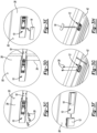
Figures 3A-3H illustrate installation of the first embodiment of the rail mechanism; -
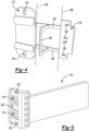
Figure 4 is a rail element of a second embodiment of a rail mechanism that slidably attaches an appliance door to a cabinet door or panel that is disposed along the exterior of the appliance door; -
Figure 5 is a sliding element of the second embodiment of the rail mechanism; and -
Figures 6A-6F illustrate installation of the second embodiment of the rail mechanism. - Embodiments of the present disclosure are described herein. It is to be understood, however, that the disclosed embodiments are merely examples and other embodiments may take various and alternative forms. The figures are not necessarily to scale; some features could be exaggerated or minimized to show details of particular components. Therefore, specific structural and functional details disclosed herein are not to be interpreted as limiting, but merely as a representative basis for teaching one skilled in the art to variously employ the embodiments. As those of ordinary skill in the art will understand, various features illustrated and described with reference to any one of the figures may be combined with features illustrated in one or more other figures to produce embodiments that are not explicitly illustrated or described. The combinations of features illustrated provide representative embodiments for typical applications. Various combinations and modifications of the features consistent with the teachings of this disclosure, however, could be desired for particular applications or implementations.
- This disclosure is not limited to the specific embodiments and methods described below, as specific components and/or conditions may, of course, vary. Furthermore, the terminology used herein is used only for the purpose of describing particular embodiments of the present invention and is not intended to be limiting in any way.
- As used in the specification and the appended claims, the singular form "a," "an," and "the" comprise plural referents unless the context clearly indicates otherwise. For example, reference to a component in the singular is intended to comprise a plurality of components.
- The term "substantially" or "about" may be used herein to describe disclosed or claimed embodiments. The term "substantially" or "about" may modify a value or relative characteristic disclosed or claimed in the present disclosure. In such instances, "substantially" or "about" may signify that the value or relative characteristic it modifies is within ± 0%, 0.1%, 0.5%, 1%, 2%, 3%, 4%, 5% or 10% of the value or relative characteristic.
- When an element or layer is referred to as being "on," "engaged to," "connected to," or "coupled to" another element or layer, it may be directly on, engaged, connected or coupled to the other element or layer, or intervening elements or layers may be present. In contrast, when an element is referred to as being "directly on," "directly engaged to," "directly connected to," or "directly coupled to" another element or layer, there may be no intervening elements or layers present. Other words used to describe the relationship between elements should be interpreted in a like fashion (e.g., "between" versus "directly between," "adjacent" versus "directly adjacent," etc.). The term "and/or" includes any and all combinations of one or more of the associated listed items.
- Although the terms first, second, third, etc. may be used to describe various elements, components, regions, layers and/or sections, these elements, components, regions, layers and/or sections should not be limited by these terms. These terms may be only used to distinguish one element, component, region, layer or section from another region, layer or section. Terms such as "first," "second," and other numerical terms when used herein do not imply a sequence or order unless clearly indicated by the context. Thus, a first element, component, region, layer or section discussed below could be termed a second element, component, region, layer or section without departing from the teachings of the example embodiments.
- Spatially relative terms, such as "inner," "outer," "beneath," "below," "lower," "above," "upper," and the like, may be used for ease of description to describe one element or feature's relationship to another element(s) or feature(s) as illustrated in the figures. Spatially relative terms may be intended to encompass different orientations of the device in use or operation in addition to the orientation depicted in the figures. For example, if the device in the figures is turned over, elements described as "below" or "beneath" other elements or features would then be oriented "above" the other elements or features. Thus, the example term "below" can encompass both an orientation of above and below. The device may be otherwise oriented (rotated 90 degrees or at other orientations) and the spatially relative descriptors used herein interpreted accordingly.
- The present disclosure relates to a built-in appliance configured for installation in a piece of kitchen furniture having a front panel hinged to a cabinet structure. The front panel is typically arranged frontally at a door of the refrigerating appliance and connected thereto by way of at least a sliding and connecting device which comprises a rail element and a sliding element.
- In the above kind of appliances, the sliding and connecting device is installed between the door of the appliance and the front panel of a piece of furniture containing the household appliance, such panel being a door of the furniture niche.
- According to such known technique it is possible to use both hinges, i.e., the hinge of the built-in appliance door and the hinge of the furniture front panel, without the need of using expensive special hinges having several axis of rotation.
- For practical and aesthetical reasons, the two "doors", i.e., the door of appliance and the panel/door of the piece of furniture, should remain as close to each other as possible during opening and closing, when there is a lateral shift between the two doors due to the two different vertical axis of hinges.
- Referring to
Figures 1 and 2 , arail 10 and a guiding element or slidingelement 12 of a first embodiment of a rail mechanism or a sliding and connecting device are illustrated, respectively. Therail 10 may be configured to slide linearly within a C-shaped profile or channel defined by the slidingelement 12. The rail defines orifices oropenings 14 configured to receive fasteners for mounting therail 10 to an interior surface of a panel or door of a piece of furniture, such as a cabinet. The slidingelement 12 defines orifices oropenings 16 configured to receive fasteners for mounting the slidingelement 12 to an upper, lower, or side edge of a door of an appliance, such as a refrigerator, that is disposed within the piece of furniture, which may be a cabinet. - The
rail 10 may include acover 18 that is disposed over the heads of the fasteners for aesthetic purposes once therail 10 is secured the interior surface of the door of the piece of furniture. Thecover 18 may include snaps, tabs, or clips 20 that engage notches orslots 22 defined by therail 10 to secure thecover 18 to therail 10. Therail 10 may define apocket 24 and thecover 18 may be disposed within thepocket 24 upon installation such thecover 18 is flush with anexterior surface 26 of therail 10, which may also be for aesthetic purposes. - The sliding
element 12 may also include acover 28 that is disposed over the heads of the fasteners for aesthetic purposes once the slidingelement 12 is secured the upper, lower, or side edge of the appliance door. Thecover 28 may include snaps, tabs, or clips 30 that engage notches orslots 32 defined by the slidingelement 12 to secure thecover 28 to the slidingelement 12. Therail 10,cover 18, and cover 28 may be formed a single component during manufacturing. The positions of thecovers rail 10 may be utilized for setting up the position of therail 10 during installation and then removed from therail 10 so that thecovers rail 10 and slidingelement 12, respectively. For example, thecovers rail 10 by cutting along dashedlines 34 before installation onto therail 10 and slidingelement 12, respectively. Bridges, bars, orarms 36 connecting therail 10 to cover 18 may then be removed fromcover 18 by cutting along dashedlines 35. One or more bridges, bars, orarms 36 connectingcover 28 to cover 18 may also have been removed when the cuts were made along dashedlines 34. - Referring to
Figures 3A-3H , installation of therail 10 onto a panel or door of a piece of furniture, such as acabinet door 38, is illustrated under two scenarios. During installation of therail 10 for either vertical set up (e.g., in first direction) according toFigure 3A (i.e., where the slidingelement 12 is fastened (e.g., viafasteners 39, bolts, rivets, etc.) to anupper edge 40 of an appliance door 42) or a horizontal set up (e.g., in second direction) according toFigure 3B (i.e., where the slidingelement 12 is fastened to aside edge 44 of the appliance door 42), the position of therail 10 relative to aside edge 46 of thecabinet door 38 may be set by aligning the outermost edge 48 of thecover 28 with theside edge 46 of the cabinet door 38 (before thecovers fasteners 39, bolts, rivets, etc.) to aninterior surface 50 of the cabinet door 38 (SeeFigure 3C ) while the outermost edge 48 of thecover 28 and theside edge 46 of thecabinet door 38 remain aligned. Once fastened to theinterior surface 50 of thecabinet door 38,cover 18,cover 28, andarms 36 may all be removed from therail 10 by cutting alonglines 34, 35 (SeeFigures 1 and3D ). Therefore, thecover 18,cover 28, andarms 36 may be collectively referred to as the removable portion. Also, during installation of therail 10 for a vertical set up according toFigure 3A , therail 10 is positioned by installing therail 10 immediately below alower edge 52 of adoor bushing 54 as illustrated byarrow 55 and securing therail 10 to theinterior surface 50 of the cabinet door 38 (SeeFigure 3C ) while therail 10 is positioned immediately below thelower edge 52 of thedoor bushing 54. More specifically, anupper edge 56 of theupper arm 36 may be aligned with thelower edge 52 ofdoor bushing 54 during a vertical set up. - The snaps, tabs, or clips 20 on the
cover 18 are inserted into and engage notches orslots 22 defined by therail 10 to secure thecover 18 to the rail 10 (SeeFigures 3E ). The slidingelement 12 is then slidably engaged with the rail 10 (SeeFigure 3F ). The slidingelement 12 is then fastened (e.g., via fasteners, bolts, rivets, etc.) to either theupper edge 40 orside edge 44 of the appliance door 42 (See.Figure 3G ) depending on whether or a vertical set up or horizontal set up is being implemented. The snaps, tabs, or clips 30 on thecover 28 are inserted into and engage notches orslots 32 defined by the slidingelement 12 to secure thecover 28 to the sliding element 12 (See.Figure 3H ). - Referring to
Figures 4 and 5 , arail 110 and a guiding element or slidingelement 112 of a second embodiment of a rail mechanism or a sliding and connecting device are illustrated, respectively. Therail 110 may be configured to slide linearly within a C-shaped profile or channel defined by the slidingelement 112. The rail defines orifices oropenings 114 configured to receive fasteners for mounting therail 110 to a side edge of a door of an appliance, such as a refrigerator, that is disposed within a piece of furniture, which may be a cabinet. The slidingelement 112 defines orifices oropenings 116 configured to receive fasteners for mounting the slidingelement 112 to an interior surface of a panel or door of the piece of furniture. - The
rail 110 may include acover 118 that is disposed over the heads of the fasteners for aesthetic purposes once therail 110 is secured the side edge of the door of the appliance. Thecover 118 may include snaps, tabs, or clips 120 that engage notches orslots 122 defined by therail 110 to secure thecover 118 to therail 110. Thecover 118 may be referred to as the rail element end cover. - The sliding
element 112 and thecover 118 may be formed as a single component during manufacturing. More specifically, the slidingelement 112 and thecover 118 may be formed as a single component via a pair of bridges, arms, or bars 124 that extend between the slidingelement 112 and thecover 118. A loop orgate 126 that is utilized for positioning the slidingelement 112 during installation extends between thebars 124. Thegate 126 may be substantially perpendicular to thebars 124. Stated in other terms, thegate 126 may be C-shaped and may extend from thebars 124 in a direction that is substantially perpendicular to the direction that thebars 124 extend with respect to the slidingelement 112 andcover 118. Substantially perpendicular may refer to any incremental value that ranges between exactly perpendicular and 15° from exactly perpendicular. - The
bars 124, thegate 126, and thecover 118 may be removed from the slidingelement 112 once the slidingelement 112 is installed onto the interior surface of the door of the piece of furniture. The removedcover 118 may then be installed onto therail 110. More specifically, thebars 124, thegate 126, and thecover 118 may be removed from the slidingelement 112 by cutting along dashedlines 128. Thecover 118 is also removed from thebars 124 and thegate 126. Therefore, thebars 124, thegate 126, and thecover 118 may be collectively referred to as the removable portion. - Referring to
Figures 6A-6F , installation of the slidingelement 112 onto a panel or door of a piece of furniture, such as acabinet door 130, is illustrated. The installation includes eight steps. Steps 2-8 are labelled inFigures 6A-6F . The first step includes opening thecabinet door 130 and opening thedoor 132 of an appliance (e.g., a refrigerator) that is disposed within the piece of furniture (e.g., a cabinet). Both doors should be opened widely (e.g., as far as the doors will open until interference with adjacent components occurs or within 30° of as far as the doors will open). Once thedoors protrusions 134 that extend outward from aside edge 136 of theappliance door 132 at step two. - Aligning the
gate 126 with theprotrusions 134 places the slidingelement 112 into a desired position on aninterior surface 138 of thecabinet door 130. Theappliance door 132 is then closed while the slidingelement 112 is held in place in the desired position on theinterior surface 138 of thecabinet door 130 at step three. The slidingelement 112 is then fastened (e.g., viafasteners 39, bolts, rivets, etc.) to theinterior surface 138 of thecabinet door 130 in the desired position at step four. Next, at Step five, thebars 124, thegate 126, and thecover 118 are removed from the slidingelement 112 by cutting along dashedlines 128. Therail 110 is then inserted into the C-shaped profile or channel defined by the slidingelement 112 at step six. Next, atstep 7, thedoors rail 110 is fastened (e.g., viafasteners 39, bolts, rivets, etc.) to theside edge 136 of theappliance door 132. Finally, atstep 8, thecover 118 is secured to the end of therail 110. - It should be understood that the designations of first, second, third, fourth, etc. for any component, state, or condition described herein may be rearranged in the claims so that they are in chronological order with respect to the claims. Furthermore, it should be understood that any component, state, or condition described herein that does not have a numerical designation may be given a designation of first, second, third, fourth, etc. in the claims if one or more of the specific component, state, or condition are claimed.
Claims (15)
- A sliding and connecting device configured for slidably connecting a refrigerator appliance door (42, 132) to a cabinet panel (38, 130) comprising:a sliding element (12, 112) defining a channel, configured to be mounted to one of the refrigerator appliance door (42, 132) or the cabinet panel (38, 130), and defining at least one first orifice (16, 116) configured to receive fasteners (39, 139) for mounting the sliding element (12, 112);a rail element (10, 110) separated from the sliding element (12, 112), configured for disposal within the channel such that rail element (10, 110) engages the sliding element (12, 112) and is slidable within the channel, configured to be mounted to the other of the refrigerator appliance door (42, 132) or the cabinet panel (38, 130), and defining at least one second orifice (14, 114) configured to receive fasteners (39, 139) for mounting the sliding element (12, 112); anda removable portion secured to a first of the sliding element (12, 112) or rail element (10, 110), wherein the removeable portion (i) includes at least one cover (18, 28, 118), (ii) includes at least one bridge (36, 124) securing the at least one cover (18, 28, 118) to the first of the sliding element (12, 112) or rail element (10, 110), (iii) is configured to engage an edge (40, 44, 136) of the refrigerator appliance door (42, 132) or an edge (46) of the cabinet panel (38, 130) for aligning the first of the sliding element (12, 112) or rail element (10, 110) relative to the refrigerator appliance door (42, 132) for installation of the first of the sliding element (12, 112) or rail element (10, 110) onto the cabinet panel (38, 130), and (iv) is configured for removal from the first of the sliding element (12, 112) or rail element (10, 110) after installation of the first of the sliding element (12, 112) or rail element (10, 110) onto the cabinet panel (38, 130), wherein the at least one cover (18, 28, 118) is configured to be secured to the sliding element (12, 112) or to the rail element (10, 110) for disposal over the at least one first orifice (16, 116) or the at least one second orifice (14, 114), respectively, upon removal of the at least one cover (18, 28, 118) from the first of the sliding element (12, 112) or rail element (10, 110).
- The sliding and connecting device of claim 1, wherein the first of the sliding element (12, 112) or rail element (10, 110) is the rail element (10), the at least one cover (18, 28, 118) includes a rail element cover (18) and a sliding element cover (28), and the at least one bridge (36, 124) includes a first bridge (36) securing the rail element cover (18) to the rail element (10) and a second bridge (36) securing the sliding element cover (28) to the rail element cover (18).
- The sliding and connecting device of claim 2, wherein the rail element (10) is configured for installation onto the cabinet panel (38) and an outer edge (48) of the sliding element cover (28) is configured to align with and engage a side edge (46) of a cabinet door (38) to align the rail element (10) relative to the refrigerator appliance door (42) in a first direction prior to installation of the rail element (10) onto the cabinet panel (38).
- The sliding and connecting device of claim 3, wherein an upper edge (56) of the first bridge (36) is configured to align with and engage a lower edge (52) of a door bushing (54) on the refrigerator appliance door (42) to align the rail element (10) relative to the refrigerator appliance door (42) in a second direction prior to installation of the rail element (10) onto the cabinet panel (38).
- The sliding and connecting device of claim 2, wherein the rail element cover (18) includes clips (20) configured to engage the rail element (10) to secure the rail element cover (18) to the rail element (10) and over the at least one second orifice (14).
- The sliding and connecting device of claim 2, wherein the sliding element cover (28) includes clips (30) configured to engage the sliding element (12) to secure the sliding element cover (28) to the sliding element (12) and over the at least one first orifice (16).
- The sliding and connecting device of claim 1, wherein the first of the sliding element (12, 112) or rail element (10, 110) is the sliding element (112), the at least one cover (18, 28, 118) includes a rail element end cover (118), and the at least one bridge (36, 124) includes first and second bridges (124) securing the rail element end cover (118) to the sliding element (112).
- The sliding and connecting device of claim 7, wherein the removable portion further comprises a gate (126) extending outward from each of and spanning the first and second bridges (124).
- The sliding and connecting device of claim 8, wherein the gate (126) is substantially perpendicular to the first and second bridges (124).
- The sliding and connecting device of claim 8, wherein the sliding element (112) is configured for installation onto the cabinet panel (130) and the gate (126) is configured to align with and engage a side edge (136) of the refrigerator appliance door (132) to align the sliding element (112) relative to the refrigerator appliance door (132) prior to installation of the sliding element (112) onto the cabinet panel (130).
- The sliding and connecting device of claim 7, wherein the rail element (110) is configured for installation onto the refrigerator appliance door (132).
- The sliding and connecting device of claim 11, wherein the rail element end cover (118) includes clips (120) configured to engage the rail element (110) to secure the rail element end cover (118) to the rail element (110) and over the at least one second orifice (114).
- A method for installation of a sliding and connecting device having a rail element (10) and a sliding element (12) to a refrigerator appliance door (42) and a cabinet panel (38) comprising:integrating the rail element (10), a rail element cover (18), and a sliding element cover (28) into a single component;positioning the rail element (10) in a first direction by aligning an edge (48) of the sliding element cover (28) with a side edge (46) of the cabinet panel (38);securing the rail element (10) to the cabinet panel (38) while the edge (48) of the sliding element cover (28) is aligned with the side edge (46) of the cabinet panel (38);engaging the sliding element (12) with the rail element (10); andsecuring the sliding element (12) to an edge (40, 44) of the refrigerator appliance door (42).
- The method of claim 13 further comprising positioning the rail element (10) in a second direction prior to securing the rail element (10) to the cabinet panel (38) by aligning an upper edge (56) of a bridge (36), which secures the rail element cover (18) to the rail element (10), with a lower edge (52) of a door bushing (54) on the refrigerator appliance door (42).
- The method of claim 13 further comprising (i) detaching the rail element cover (18) from the rail element (10) via severing a bridge (36) that connects the rail element cover (18) to the rail element (10), (ii) reattaching the rail element cover (18) to the rail element (10) via a first set of clips (20), (iii) detaching the sliding element (10) from the rail element (10) via severing a second bridge (36) that connects the sliding element cover (28) to the rail element cover (18), and (iv) attaching the sliding element cover (28) to the sliding element (12) via a second set of clips (30).
Applications Claiming Priority (2)
| Application Number | Priority Date | Filing Date | Title |
|---|---|---|---|
| US202263321307P | 2022-03-18 | 2022-03-18 | |
| US18/161,492 US20230296307A1 (en) | 2022-03-18 | 2023-01-30 | Slide mechanism for a built-in refrigerator |
Publications (2)
| Publication Number | Publication Date |
|---|---|
| EP4246069A1 true EP4246069A1 (en) | 2023-09-20 |
| EP4246069B1 EP4246069B1 (en) | 2025-09-03 |
Family
ID=85174166
Family Applications (1)
| Application Number | Title | Priority Date | Filing Date |
|---|---|---|---|
| EP23154801.7A Active EP4246069B1 (en) | 2022-03-18 | 2023-02-02 | Slide mechanism for a built-in refrigerator |
Country Status (2)
| Country | Link |
|---|---|
| US (1) | US20230296307A1 (en) |
| EP (1) | EP4246069B1 (en) |
Families Citing this family (1)
| Publication number | Priority date | Publication date | Assignee | Title |
|---|---|---|---|---|
| US11635248B2 (en) * | 2021-06-18 | 2023-04-25 | Whirlpool Corporation | Built-in refrigerator |
Citations (3)
| Publication number | Priority date | Publication date | Assignee | Title |
|---|---|---|---|---|
| DE19704698A1 (en) * | 1997-02-07 | 1998-08-13 | Bosch Siemens Hausgeraete | Refrigerator for installation in a furniture niche |
| EP3032022A1 (en) * | 2014-12-08 | 2016-06-15 | BSH Hausgeräte GmbH | Method for mounting a towing device and assembly kit |
| EP3789705A1 (en) * | 2019-09-05 | 2021-03-10 | Electrolux Appliances Aktiebolag | A mounting tool for a connection system of a door of a built-in domestic appliance to a door of a furniture |
-
2023
- 2023-01-30 US US18/161,492 patent/US20230296307A1/en not_active Abandoned
- 2023-02-02 EP EP23154801.7A patent/EP4246069B1/en active Active
Patent Citations (3)
| Publication number | Priority date | Publication date | Assignee | Title |
|---|---|---|---|---|
| DE19704698A1 (en) * | 1997-02-07 | 1998-08-13 | Bosch Siemens Hausgeraete | Refrigerator for installation in a furniture niche |
| EP3032022A1 (en) * | 2014-12-08 | 2016-06-15 | BSH Hausgeräte GmbH | Method for mounting a towing device and assembly kit |
| EP3789705A1 (en) * | 2019-09-05 | 2021-03-10 | Electrolux Appliances Aktiebolag | A mounting tool for a connection system of a door of a built-in domestic appliance to a door of a furniture |
Also Published As
| Publication number | Publication date |
|---|---|
| EP4246069B1 (en) | 2025-09-03 |
| US20230296307A1 (en) | 2023-09-21 |
Similar Documents
| Publication | Publication Date | Title |
|---|---|---|
| US10920475B2 (en) | Sliding-door closer set | |
| US8904712B2 (en) | Method of reversing hand configurations of sliding doors | |
| US3969788A (en) | Door lock hinge | |
| US20060150524A1 (en) | Installation method for a storm door | |
| US20190264485A1 (en) | Upwardly Pivoted Window with Spring Biased Sash | |
| US10167658B2 (en) | Side-load hung window assembly with sash guides | |
| US20230296307A1 (en) | Slide mechanism for a built-in refrigerator | |
| US10995534B1 (en) | Door with hidden door closer | |
| US11008795B1 (en) | Door with hidden door closer | |
| EP2940236B1 (en) | Damper, striker assembly and vehicle | |
| US20230221059A1 (en) | Built-in refrigerator | |
| JP2019035203A (en) | Sliding door device and attaching method of sliding door device | |
| KR100988496B1 (en) | Sliding door for furniture | |
| JP7862282B2 (en) | opening device | |
| JP7862281B2 (en) | opening device | |
| CN214997120U (en) | Glass door with easily installed hinge | |
| CN223190316U (en) | Rotating shaft section bar and PT door capable of being opened in free direction | |
| RU2780786C2 (en) | Frame with protection device for sliding sash or for sash with lifting and sliding mechanism of window or door | |
| JP7801200B2 (en) | opening device | |
| US20020194703A1 (en) | Adjustable hinge | |
| EP3854971B1 (en) | A hinge locator | |
| KR200325016Y1 (en) | Door stopper | |
| CA2941936C (en) | Side-load hung window assembly with sash guides | |
| JP2024058427A (en) | Opening device | |
| KR102003102B1 (en) | Hardware assembly for window |
Legal Events
| Date | Code | Title | Description |
|---|---|---|---|
| PUAI | Public reference made under article 153(3) epc to a published international application that has entered the european phase |
Free format text: ORIGINAL CODE: 0009012 |
|
| STAA | Information on the status of an ep patent application or granted ep patent |
Free format text: STATUS: THE APPLICATION HAS BEEN PUBLISHED |
|
| AK | Designated contracting states |
Kind code of ref document: A1 Designated state(s): AL AT BE BG CH CY CZ DE DK EE ES FI FR GB GR HR HU IE IS IT LI LT LU LV MC ME MK MT NL NO PL PT RO RS SE SI SK SM TR |
|
| STAA | Information on the status of an ep patent application or granted ep patent |
Free format text: STATUS: REQUEST FOR EXAMINATION WAS MADE |
|
| 17P | Request for examination filed |
Effective date: 20240319 |
|
| RBV | Designated contracting states (corrected) |
Designated state(s): AL AT BE BG CH CY CZ DE DK EE ES FI FR GB GR HR HU IE IS IT LI LT LU LV MC ME MK MT NL NO PL PT RO RS SE SI SK SM TR |
|
| RAP1 | Party data changed (applicant data changed or rights of an application transferred) |
Owner name: BEKO EUROPE MANAGEMENT S.R.L. |
|
| RAP3 | Party data changed (applicant data changed or rights of an application transferred) |
Owner name: BEKO EUROPE MANAGEMENT S.R.L. |
|
| P01 | Opt-out of the competence of the unified patent court (upc) registered |
Free format text: CASE NUMBER: APP_61080/2024 Effective date: 20241114 |
|
| GRAP | Despatch of communication of intention to grant a patent |
Free format text: ORIGINAL CODE: EPIDOSNIGR1 |
|
| STAA | Information on the status of an ep patent application or granted ep patent |
Free format text: STATUS: GRANT OF PATENT IS INTENDED |
|
| RIC1 | Information provided on ipc code assigned before grant |
Ipc: F25D 23/10 20060101ALI20250409BHEP Ipc: F25D 23/02 20060101AFI20250409BHEP |
|
| INTG | Intention to grant announced |
Effective date: 20250423 |
|
| GRAS | Grant fee paid |
Free format text: ORIGINAL CODE: EPIDOSNIGR3 |
|
| GRAA | (expected) grant |
Free format text: ORIGINAL CODE: 0009210 |
|
| STAA | Information on the status of an ep patent application or granted ep patent |
Free format text: STATUS: THE PATENT HAS BEEN GRANTED |
|
| AK | Designated contracting states |
Kind code of ref document: B1 Designated state(s): AL AT BE BG CH CY CZ DE DK EE ES FI FR GB GR HR HU IE IS IT LI LT LU LV MC ME MK MT NL NO PL PT RO RS SE SI SK SM TR |
|
| REG | Reference to a national code |
Ref country code: CH Ref legal event code: EP |
|
| REG | Reference to a national code |
Ref country code: DE Ref legal event code: R096 Ref document number: 602023006201 Country of ref document: DE |
|
| REG | Reference to a national code |
Ref country code: IE Ref legal event code: FG4D |
|
| REG | Reference to a national code |
Ref country code: NL Ref legal event code: MP Effective date: 20250903 |
|
| PG25 | Lapsed in a contracting state [announced via postgrant information from national office to epo] |
Ref country code: NO Free format text: LAPSE BECAUSE OF FAILURE TO SUBMIT A TRANSLATION OF THE DESCRIPTION OR TO PAY THE FEE WITHIN THE PRESCRIBED TIME-LIMIT Effective date: 20251203 |
|
| REG | Reference to a national code |
Ref country code: LT Ref legal event code: MG9D |
|
| PG25 | Lapsed in a contracting state [announced via postgrant information from national office to epo] |
Ref country code: FI Free format text: LAPSE BECAUSE OF FAILURE TO SUBMIT A TRANSLATION OF THE DESCRIPTION OR TO PAY THE FEE WITHIN THE PRESCRIBED TIME-LIMIT Effective date: 20250903 |
|
| PG25 | Lapsed in a contracting state [announced via postgrant information from national office to epo] |
Ref country code: HR Free format text: LAPSE BECAUSE OF FAILURE TO SUBMIT A TRANSLATION OF THE DESCRIPTION OR TO PAY THE FEE WITHIN THE PRESCRIBED TIME-LIMIT Effective date: 20250903 |
|
| PG25 | Lapsed in a contracting state [announced via postgrant information from national office to epo] |
Ref country code: GR Free format text: LAPSE BECAUSE OF FAILURE TO SUBMIT A TRANSLATION OF THE DESCRIPTION OR TO PAY THE FEE WITHIN THE PRESCRIBED TIME-LIMIT Effective date: 20251204 |
|
| PG25 | Lapsed in a contracting state [announced via postgrant information from national office to epo] |
Ref country code: SE Free format text: LAPSE BECAUSE OF FAILURE TO SUBMIT A TRANSLATION OF THE DESCRIPTION OR TO PAY THE FEE WITHIN THE PRESCRIBED TIME-LIMIT Effective date: 20250903 |
|
| PG25 | Lapsed in a contracting state [announced via postgrant information from national office to epo] |
Ref country code: LV Free format text: LAPSE BECAUSE OF FAILURE TO SUBMIT A TRANSLATION OF THE DESCRIPTION OR TO PAY THE FEE WITHIN THE PRESCRIBED TIME-LIMIT Effective date: 20250903 |
|
| PG25 | Lapsed in a contracting state [announced via postgrant information from national office to epo] |
Ref country code: PL Free format text: LAPSE BECAUSE OF FAILURE TO SUBMIT A TRANSLATION OF THE DESCRIPTION OR TO PAY THE FEE WITHIN THE PRESCRIBED TIME-LIMIT Effective date: 20250903 Ref country code: BG Free format text: LAPSE BECAUSE OF FAILURE TO SUBMIT A TRANSLATION OF THE DESCRIPTION OR TO PAY THE FEE WITHIN THE PRESCRIBED TIME-LIMIT Effective date: 20250903 |
|
| PG25 | Lapsed in a contracting state [announced via postgrant information from national office to epo] |
Ref country code: RS Free format text: LAPSE BECAUSE OF FAILURE TO SUBMIT A TRANSLATION OF THE DESCRIPTION OR TO PAY THE FEE WITHIN THE PRESCRIBED TIME-LIMIT Effective date: 20251203 |
|
| PG25 | Lapsed in a contracting state [announced via postgrant information from national office to epo] |
Ref country code: ES Free format text: LAPSE BECAUSE OF FAILURE TO SUBMIT A TRANSLATION OF THE DESCRIPTION OR TO PAY THE FEE WITHIN THE PRESCRIBED TIME-LIMIT Effective date: 20250903 |
|
| REG | Reference to a national code |
Ref country code: AT Ref legal event code: MK05 Ref document number: 1833485 Country of ref document: AT Kind code of ref document: T Effective date: 20250903 |
|
| PG25 | Lapsed in a contracting state [announced via postgrant information from national office to epo] |
Ref country code: NL Free format text: LAPSE BECAUSE OF FAILURE TO SUBMIT A TRANSLATION OF THE DESCRIPTION OR TO PAY THE FEE WITHIN THE PRESCRIBED TIME-LIMIT Effective date: 20250903 |
|
| PG25 | Lapsed in a contracting state [announced via postgrant information from national office to epo] |
Ref country code: SM Free format text: LAPSE BECAUSE OF FAILURE TO SUBMIT A TRANSLATION OF THE DESCRIPTION OR TO PAY THE FEE WITHIN THE PRESCRIBED TIME-LIMIT Effective date: 20250903 |
|
| PGFP | Annual fee paid to national office [announced via postgrant information from national office to epo] |
Ref country code: DE Payment date: 20260220 Year of fee payment: 4 |
|
| PG25 | Lapsed in a contracting state [announced via postgrant information from national office to epo] |
Ref country code: AT Free format text: LAPSE BECAUSE OF FAILURE TO SUBMIT A TRANSLATION OF THE DESCRIPTION OR TO PAY THE FEE WITHIN THE PRESCRIBED TIME-LIMIT Effective date: 20250903 |
|
| PGFP | Annual fee paid to national office [announced via postgrant information from national office to epo] |
Ref country code: IT Payment date: 20260228 Year of fee payment: 4 |
|
| PG25 | Lapsed in a contracting state [announced via postgrant information from national office to epo] |
Ref country code: IS Free format text: LAPSE BECAUSE OF FAILURE TO SUBMIT A TRANSLATION OF THE DESCRIPTION OR TO PAY THE FEE WITHIN THE PRESCRIBED TIME-LIMIT Effective date: 20260103 |
|
| PGFP | Annual fee paid to national office [announced via postgrant information from national office to epo] |
Ref country code: FR Payment date: 20260227 Year of fee payment: 4 |
|
| PG25 | Lapsed in a contracting state [announced via postgrant information from national office to epo] |
Ref country code: CZ Free format text: LAPSE BECAUSE OF FAILURE TO SUBMIT A TRANSLATION OF THE DESCRIPTION OR TO PAY THE FEE WITHIN THE PRESCRIBED TIME-LIMIT Effective date: 20250903 Ref country code: PT Free format text: LAPSE BECAUSE OF FAILURE TO SUBMIT A TRANSLATION OF THE DESCRIPTION OR TO PAY THE FEE WITHIN THE PRESCRIBED TIME-LIMIT Effective date: 20260105 |
|
| PG25 | Lapsed in a contracting state [announced via postgrant information from national office to epo] |
Ref country code: SK Free format text: LAPSE BECAUSE OF FAILURE TO SUBMIT A TRANSLATION OF THE DESCRIPTION OR TO PAY THE FEE WITHIN THE PRESCRIBED TIME-LIMIT Effective date: 20250903 Ref country code: EE Free format text: LAPSE BECAUSE OF FAILURE TO SUBMIT A TRANSLATION OF THE DESCRIPTION OR TO PAY THE FEE WITHIN THE PRESCRIBED TIME-LIMIT Effective date: 20250903 |