EP4246058A1 - Controller for use with a waste heat recovery refrigeration unit system, control method, and program - Google Patents
Controller for use with a waste heat recovery refrigeration unit system, control method, and program Download PDFInfo
- Publication number
- EP4246058A1 EP4246058A1 EP23153882.8A EP23153882A EP4246058A1 EP 4246058 A1 EP4246058 A1 EP 4246058A1 EP 23153882 A EP23153882 A EP 23153882A EP 4246058 A1 EP4246058 A1 EP 4246058A1
- Authority
- EP
- European Patent Office
- Prior art keywords
- heat
- refrigerant
- waste heat
- heat recovery
- unit
- Prior art date
- Legal status (The legal status is an assumption and is not a legal conclusion. Google has not performed a legal analysis and makes no representation as to the accuracy of the status listed.)
- Pending
Links
Images


Classifications
-
- F—MECHANICAL ENGINEERING; LIGHTING; HEATING; WEAPONS; BLASTING
- F25—REFRIGERATION OR COOLING; COMBINED HEATING AND REFRIGERATION SYSTEMS; HEAT PUMP SYSTEMS; MANUFACTURE OR STORAGE OF ICE; LIQUEFACTION SOLIDIFICATION OF GASES
- F25B—REFRIGERATION MACHINES, PLANTS OR SYSTEMS; COMBINED HEATING AND REFRIGERATION SYSTEMS; HEAT PUMP SYSTEMS
- F25B25/00—Machines, plants or systems, using a combination of modes of operation covered by two or more of the groups F25B1/00 - F25B23/00
- F25B25/005—Machines, plants or systems, using a combination of modes of operation covered by two or more of the groups F25B1/00 - F25B23/00 using primary and secondary systems
-
- F—MECHANICAL ENGINEERING; LIGHTING; HEATING; WEAPONS; BLASTING
- F25—REFRIGERATION OR COOLING; COMBINED HEATING AND REFRIGERATION SYSTEMS; HEAT PUMP SYSTEMS; MANUFACTURE OR STORAGE OF ICE; LIQUEFACTION SOLIDIFICATION OF GASES
- F25B—REFRIGERATION MACHINES, PLANTS OR SYSTEMS; COMBINED HEATING AND REFRIGERATION SYSTEMS; HEAT PUMP SYSTEMS
- F25B27/00—Machines, plants or systems, using particular sources of energy
- F25B27/02—Machines, plants or systems, using particular sources of energy using waste heat, e.g. from internal-combustion engines
-
- F—MECHANICAL ENGINEERING; LIGHTING; HEATING; WEAPONS; BLASTING
- F25—REFRIGERATION OR COOLING; COMBINED HEATING AND REFRIGERATION SYSTEMS; HEAT PUMP SYSTEMS; MANUFACTURE OR STORAGE OF ICE; LIQUEFACTION SOLIDIFICATION OF GASES
- F25B—REFRIGERATION MACHINES, PLANTS OR SYSTEMS; COMBINED HEATING AND REFRIGERATION SYSTEMS; HEAT PUMP SYSTEMS
- F25B29/00—Combined heating and refrigeration systems, e.g. operating alternately or simultaneously
-
- F—MECHANICAL ENGINEERING; LIGHTING; HEATING; WEAPONS; BLASTING
- F25—REFRIGERATION OR COOLING; COMBINED HEATING AND REFRIGERATION SYSTEMS; HEAT PUMP SYSTEMS; MANUFACTURE OR STORAGE OF ICE; LIQUEFACTION SOLIDIFICATION OF GASES
- F25B—REFRIGERATION MACHINES, PLANTS OR SYSTEMS; COMBINED HEATING AND REFRIGERATION SYSTEMS; HEAT PUMP SYSTEMS
- F25B49/00—Arrangement or mounting of control or safety devices
-
- F—MECHANICAL ENGINEERING; LIGHTING; HEATING; WEAPONS; BLASTING
- F25—REFRIGERATION OR COOLING; COMBINED HEATING AND REFRIGERATION SYSTEMS; HEAT PUMP SYSTEMS; MANUFACTURE OR STORAGE OF ICE; LIQUEFACTION SOLIDIFICATION OF GASES
- F25B—REFRIGERATION MACHINES, PLANTS OR SYSTEMS; COMBINED HEATING AND REFRIGERATION SYSTEMS; HEAT PUMP SYSTEMS
- F25B2600/00—Control issues
- F25B2600/25—Control of valves
- F25B2600/2515—Flow valves
Definitions
- the present invention relates to a controller, a waste heat recovery refrigeration unit system, a control method, and a program.
- Patent Document 1 discloses a heat pump system including a refrigeration unit including a variable capacity compressor and an evaporator, a water medium circuit that recovers waste heat of a refrigerant circuit by exchanging heat with a refrigerant circulating through the refrigerant circuit of the refrigeration unit, and an auxiliary heat source that heats a water medium circulating through the water medium circuit, and control of causing the auxiliary heat source to perform operation when a difference between an outlet temperature of the water medium in the refrigerant-water heat exchanger and a target outlet temperature is equal to or greater than a threshold value in the heat pump system.
- waste heat of the refrigerant circuit recovered by the water medium circuit can be supplied to loads such as heating and hot-water supply.
- Patent Document 1 mentions operation in which a refrigeration unit and a water heater or a refrigeration unit and heating are combined, but does not mention a condition under which use of waste heat of a refrigeration unit for operation of heating, hot-water supply, or the like allows operation of the entire system including the refrigeration unit and the heating to be made efficient.
- Patent Document 1 Japanese Patent No. 5400177
- an object of the present invention is to provide a controller, a waste heat recovery refrigeration unit system, a control method, and a program that can solve the above-described problems.
- a controller is a controller of a waste heat recovery refrigeration unit system including a first waste heat recovery device that recovers heat by exchanging heat with a first refrigerant circulating through a refrigerant circuit of a first refrigeration unit that cools a refrigerating chamber and/or a second refrigerant circulating through a refrigerant circuit of a second refrigeration unit that cools a freezing chamber, and supplies, to an air conditioning unit, the heat having been recovered, and a second waste heat recovery device that recovers heat by exchanging heat with the first refrigerant and/or the second refrigerant, and supplies, to a hot-water supply unit, the heat having been recovered, the waste heat recovery refrigeration unit system being configured such that the first waste heat recovery device can switch whether to exchange heat with each of the first refrigerant and the second refrigerant, and the second waste heat recovery device can switch whether to exchange heat with each of the first refrigerant and the second refrigerant, the controller including a heat recovery control unit that
- a waste heat recovery refrigeration unit system includes: a first refrigeration unit that cools a refrigerating chamber; a second refrigeration unit that cools the freezing chamber; an air conditioning unit; a hot-water supply unit; a first waste heat recovery device including a first heat exchange circuit that exchanges heat between a first refrigerant circulating through a first refrigerant circuit of the first refrigeration unit and a first water medium, a second heat exchange circuit that exchanges heat between a second refrigerant circulating through a second refrigerant circuit of the second refrigeration unit and the first water medium, a circuit that supplies heat of the first water medium subjected to heat exchange to the air conditioning unit, a valve that is provided in the first heat exchange circuit and switches whether the first water medium flows through the first heat exchange circuit, and a valve that is provided in the second heat exchange circuit and switches whether the first water medium flows through the second heat exchange circuit; a second waste heat recovery device including a third heat exchange circuit that exchanges heat between the first refrigerant and a
- a control method is a control method of a waste heat recovery refrigeration unit system including a first waste heat recovery device that recovers heat by exchanging heat with a first refrigerant circulating through a refrigerant circuit of a first refrigeration unit that cools a refrigerating chamber and/or a second refrigerant circulating through a refrigerant circuit of a second refrigeration unit that cools a freezing chamber, and supplies, to an air conditioning unit, the heat having been recovered, and a second waste heat recovery device that recovers heat by exchanging heat with the first refrigerant and/or the second refrigerant, and supplies, to a hot-water supply unit, the heat having been recovered, the waste heat recovery refrigeration unit system being configured such that the first waste heat recovery device can switch whether to exchange heat with each of the first refrigerant and the second refrigerant, and the second waste heat recovery device can switch whether to exchange heat with each of the first refrigerant and the second refrigerant, the control method including controlling whether each of
- a program causes a computer to execute processing of a control method of a waste heat recovery refrigeration unit system including a first waste heat recovery device that recovers heat by exchanging heat with a first refrigerant circulating through a refrigerant circuit of a first refrigeration unit that cools a refrigerating chamber and/or a second refrigerant circulating through a refrigerant circuit of a second refrigeration unit that cools a freezing chamber, and supplies, to an air conditioning unit, the heat having been recovered, and a second waste heat recovery device that recovers heat by exchanging heat with the first refrigerant and/or the second refrigerant, and supplies, to a hot-water supply unit, the heat having been recovered, the waste heat recovery refrigeration unit system being configured such that the first waste heat recovery device can switch whether to exchange heat with each of the first refrigerant and the second refrigerant, and the second waste heat recovery device can switch whether to exchange heat with each of the first refrigerant and the second refrigerant, the processing
- the overall operation efficiency of a system including a refrigeration unit and a loading device can be improved utilizing its waste heat.
- FIGS. 1 to 4 a waste heat recovery refrigeration unit system according to one embodiment of the present disclosure will be described with reference to FIGS. 1 to 4 .
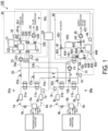
- FIG. 1 is a view illustrating an example of the waste heat recovery refrigeration unit system according to the embodiment.
- a waste heat recovery refrigeration unit system 100 is used in a store such as a supermarket, and includes a refrigeration unit 1a that cools a refrigerated showcase, a refrigeration unit 1b that cools a freezer showcase, an air conditioning unit 30, a hot-water supply unit 40, a waste heat recovery device 10 that recovers waste heat of the refrigeration unit 1a and the refrigeration unit 1b and supplies the waste heat to the hot-water supply unit 40 of the store, a waste heat recovery device 20 that recovers waste heat of the refrigeration unit 1a and the refrigeration unit 1b and supplies the waste heat to the air conditioning unit 30 of the store, a system controller 50, and temperature sensors 60a to 60d.
- the temperature sensors 60a to 60d measure outside temperatures.
- the outside temperature is an ambient temperature of a site where each device of the refrigeration units 1a and 1b, the air conditioner of the air conditioning unit 30, and a water heater 41 is installed.
- the temperature sensor 60a is provided near the installation site of the refrigeration unit 1a and measures the ambient temperature of the refrigeration unit 1a.
- the temperature sensor 60b is provided near the installation site of the refrigeration unit 1b and measures the ambient temperature of the refrigeration unit 1b.
- the temperature sensor 60c is provided near an installation site of an air conditioner not illustrated and measures the ambient temperature of the air conditioner.
- the temperature sensor 60d is provided near the installation site of the water heater 41 and measures the ambient temperature of the water heater 41.
- the outside temperature measured by the temperature sensor 60a is transmitted to a control unit 7a and the system controller 50.
- the outside temperature measured by the temperature sensor 60b is transmitted to a control unit 7b and the system controller 50.
- the outside temperature measured by the temperature sensor 60c is transmitted to a control unit 35 and the system controller 50.
- the outside temperature measured by the temperature sensor 60d is transmitted to a control unit 46 and the system controller 50.
- the refrigeration unit 1a includes a compressor 2a, a gas cooler 3a, an expansion valve 4a, an evaporator 5a, a refrigerant pipe 6a connecting them, and the control unit 7a.
- the compressor 2a compresses and discharges the refrigerant.
- a heat exchanger 11a of the waste heat recovery device 10 and a heat exchanger 21a of the waste heat recovery device 20 are connected (inserted) between the compressor 2a and the gas cooler 3a, and the refrigerant of the refrigeration unit 1a flows through the heat exchanger 11a and the heat exchanger 21a.
- heat of the high-temperature and high-pressure refrigerant is recovered by the refrigerant (water) in the waste heat recovery device 10 and supplied to the hot-water supply unit 40.
- heat of the high-temperature and high-pressure refrigerant is recovered by the refrigerant (water) of the waste heat recovery device 20 and supplied to the air conditioning unit 30.
- the refrigerant that has passed through the heat exchanger 11a and the heat exchanger 21a exchanges heat with air in the gas cooler 3a to radiate heat, and is condensed.
- the condensed refrigerant is decompressed and expanded by the expansion valve 4a and supplied to the evaporator 5a.
- the refrigerant supplied to the evaporator 5a absorbs heat of the refrigerated showcase to cool air in the refrigerated showcase.
- the refrigerant vaporized in the evaporator 5a is sucked into the compressor 2a.
- the refrigerant is compressed by the compressor 2a and circulates through the above path again.
- CO 2 is used as the refrigerant of the refrigeration unit 1a.
- the CO 2 refrigerant enters a supercritical state in a normal temperature range of about 31 °C.
- control unit 7a When the outside temperature measured by the temperature sensor 60a becomes equal to or greater than a predetermined threshold value, or when heat is recovered by the waste heat recovery device 10 or the waste heat recovery device 20, the control unit 7a operates in a state where the CO 2 refrigerant becomes supercritical at high pressure, and otherwise operates in a state where the high pressure becomes subcritical.
- the refrigeration unit 1b includes a compressor 2b, a gas cooler 3b, an expansion valve 4b, an evaporator 5b, a refrigerant pipe 6b connecting them, and the control unit 7b.
- the compressor 2b compresses and discharges the refrigerant.
- a heat exchanger 11b of the waste heat recovery device 10 and a heat exchanger 21b of the waste heat recovery device 20 are connected (inserted) between the compressor 2b and the gas cooler 3b, and the refrigerant of the refrigeration unit 1b flows through the heat exchanger 11b and the heat exchanger 21b.
- heat of the high-temperature and high-pressure refrigerant is recovered by the refrigerant (water) in the waste heat recovery device 10 and supplied to the hot-water supply unit 40.
- heat of the high-temperature and high-pressure refrigerant is recovered by the refrigerant (water) of the waste heat recovery device 20 and supplied to the air conditioning unit 30.
- the refrigerant that has passed through the heat exchanger 11b and the heat exchanger 21b exchanges heat with air in the gas cooler 3b to radiate heat, and is condensed.
- the condensed refrigerant is decompressed and expanded by the expansion valve 4b and supplied to the evaporator 5b.
- the refrigerant supplied to the evaporator 5b absorbs heat of the freezer showcase to cool air in the freezer showcase.
- the refrigerant vaporized in the evaporator 5b is sucked into the compressor 2b.
- the CO 2 refrigerant is compressed by the compressor 2b and circulates through the above path again.
- the refrigerant of the refrigeration unit 1b for example, CO 2 is used.
- the control unit 7b operates in a state where the CO 2 refrigerant becomes supercritical at high pressure, and otherwise operates in a state where the high pressure becomes subcritical.
- the control unit 7b may operate in a state of supercritical at high pressure regardless of the outside temperature measured by the temperature sensor 60b. Comparing the refrigeration units 1a and 1b, the evaporation temperature is higher in the refrigeration unit 1a, and the refrigerant temperature at high pressure is higher in the refrigeration unit 1b.
- the waste heat recovery device 10 includes the heat exchanger 11a, the heat exchanger 11b, a pump 13, a heat exchanger 14, a pipe 15a that branches from a pipe 15b and is connected to the heat exchanger 11a on an upstream side in the flow direction of a water medium relative to the heat exchanger 11b and is connected to the pipe 15b on a downstream side in the flow direction of the water medium of the heat exchanger 11b, a valve 12a provided in the pipe 15a, the pipe 15b connecting the heat exchanger 11b, the pump 13, and the heat exchanger 14 and allowing the water medium to circulate among them, a valve 12b provided between a branching point to the pipe 15a on the upstream side in the flow direction of the water medium of the pipe 15b and the heat exchanger 11b, and a control unit 16.
- the control unit 16 controls start and stop of the pump 13 and open and close of the valve 12a and the valve 12b.
- the valve 12a enters an open state
- the valve 12b enters a close state
- the water medium circulates through the pipe 15a, and absorbs heat from the CO 2 refrigerant of the refrigeration unit 1a in the heat exchanger 11a, so that the temperature of the water medium increases.
- the water medium with risen temperature flows through the pipe 15a, merges to the pipe 15b, flows through the pipe 15b to reach the heat exchanger 14, and in the heat exchanger 14, heat is exchanged between the water medium flowing through the pipe 15b and the water medium on the hot-water supply unit 40 side to raise the temperature of the water medium on the hot-water supply unit 40 side.
- valve 12a When the pump 13 is started, the valve 12a enters a close state, and the valve 12b enters an open state, the water medium circulates through the pipe 15b, and absorbs heat from the CO 2 refrigerant of the refrigeration unit 1b in the heat exchanger 11b, so that the temperature of the water medium increases.
- the water medium with risen temperature flows through the pipe 15b to reach the heat exchanger 14, and in the heat exchanger 14, heat is exchanged between the water medium flowing through the pipe 15b and the water medium on the hot-water supply unit 40 side to raise the temperature of the water medium on the hot-water supply unit 40 side.
- the waste heat recovery device 20 includes the heat exchanger 21a, the heat exchanger 21b, a pump 23, a pipe 24b that branches from a pipe 24a and is connected to the heat exchanger 21b on an upstream side in the flow direction of the water medium relative to the heat exchanger 21a and is connected to the pipe 24a on a downstream side in the flow direction of the water medium of the heat exchanger 21a, a valve 22b provided on the pipe 24b, the pipe 24a connecting the heat exchanger 21a, the pump 23, and the air conditioning unit 30 side and allowing the water medium to circulate among them, a valve 22a provided between a branching point to the pipe 24b on the upstream side in the flow direction of the water medium of the pipe 24a and the heat exchanger 21a, and a control unit 25.
- the control unit 25 controls start and stop of the pump 23 and open and close of the valve 22a and the valve 22b.
- the valve 22a enters an open state
- the valve 22b enters a close state
- the water medium circulates through the pipe 24a and the air conditioning unit 30, and absorbs heat from the CO 2 refrigerant of the refrigeration unit 1a in the heat exchanger 21a, so that the temperature of the water medium increases.
- the water medium with risen temperature flows through the pipe 24a to reach a tank 33 of the air conditioning unit 30, the hot water in the tank 33 is supplied to the air conditioner not illustrated, and the water returning from the air conditioner reaches a tank 32.
- the pump 23 of the waste heat recovery device 20 sucks water from the tank 32 of the air conditioning unit 30 and sends the water to the heat exchanger 21a.
- the valve 22a enters a close state, and the valve 22b enters an open state, the water medium reaches the heat exchanger 21b through the pipe 24b, and absorbs heat from the CO 2 refrigerant of the refrigeration unit 1b in the heat exchanger 21b, so that the temperature of the water medium increases.
- the water medium with risen temperature flows through the pipe 24b, merges with the pipe 24a, reaches the tank 33 of the air conditioning unit 30, and is supplied to the air conditioner not illustrated.
- the pump 23 sucks water from the tank 32 and sends the water to the heat exchanger 21b.
- valve 22a When the pump 23 is started, the valve 22a enters an open state, and the valve 22b enters an open state, heat is exchanged in both the heat exchanger 21a and the heat exchanger 21b, the temperature of the water medium flowing through the waste heat recovery device 20 rises, and the water medium is supplied to the tank 33 and used for air conditioning.
- the water after being used is sent to the tank 32, and in the waste heat recovery device 20, the water in the tank 32 is sent to the heat exchanger 21a and/or the heat exchanger 21b, and the waste heat of the refrigeration units 1a and 1b is recovered to raise the temperature of the water medium.
- the air conditioning unit 30 includes a heat source device 31 for air conditioning, the tank 32, the tank 33, a pump 34, and the control unit 35.
- the heat source device 31 and the tank 32 are connected via a pipe 352.
- the heat source device 31 and the tank 33 are connected via a pipe 353.
- the tank 33 is connected to the air conditioner not illustrated via a pipe 354, and by driving of the pump 34 provided in the pipe 354, the hot water in the tank 33 is supplied to the air conditioner not illustrated.
- the control unit 35 controls the heat source device 31 and the pump 34.
- the control unit 35 acquires and stores information on the amount and temperature of the hot water stored in the tank 33 and the heat storage amount.
- a temperature sensor 331 and a flow rate sensor 332 are provided in the flow path on the tank 33 inlet side of the water medium supplied from the waste heat recovery device 20.
- a temperature sensor 333 and a flow rate sensor 334 are provided in the flow path on the tank 33 inlet side of the water medium supplied from the heat source device 31.
- a temperature sensor 335 and a flow rate sensor 336 are provided in the flow path on the tank 33 outlet side of the hot water to be supplied to the air conditioner not illustrated.
- a temperature sensor 321 is provided in the flow path from the tank 32 to the pump 23, a temperature sensor 322 is provided in the flow path from the tank 32 to the heat source device 31, and a temperature sensor 351a is provided in the flow path of a pipe 351.
- the control unit 35 acquires the temperatures measured by the temperature sensors 321, 322, 331, 333, 335, and 351a and the flow rates measured by the flow rate sensors 332, 334, and 336.
- the control unit 35 acquires and stores the temperature measured by the temperature sensor 335 at each time as information on the temperature of the hot water stored in the tank 33.
- the control unit 35 acquires and stores, as information on the amount of hot water stored in the tank 33, a value obtained by temporally adding a value obtained by subtracting the flow rate measured by the flow rate sensor 336 from the sum of the flow rate measured by the flow rate sensor 332 and the flow rate measured by the flow rate sensor 334 at each time.
- the control unit 35 calculates the waste heat recovery amount by (temperature measured by the temperature sensor 331 at each time - temperature measured by the temperature sensor 321 at each time) ⁇ flow rate measured by the flow rate sensor 332 at each time, and calculates the output from the heat source device 31 by (temperature measured by the temperature sensor 333 at each time - temperature measured by the temperature sensor 322 at each time) ⁇ flow rate measured by the flow rate sensor 334 at each time.
- the control unit 35 calculates the amount of heat actually consumed on the load side by (temperature measured by the temperature sensor 335 at each time - temperature measured by the temperature sensor 351a at each time) ⁇ flow rate measured by the flow rate sensor 336 at each time.
- the control unit 35 calculates the heat storage amount of the tank 33 by temporally adding a value obtained by subtracting the amount of heat actually consumed on the load side from the sum of the calculated waste heat recovery amount and the output from the heat source device 31.
- the control unit 35 operates the heat source device 31 according to an operation mode (cooling, heating, stopping, and the like) or the load of the air conditioner. For example, when the air conditioner is in a heating mode, the heat source device 31 heats the water in the tank 32 and supplies the hot water after heated to the tank 33. Hot water generated by the heat source device 31 and hot water whose heat is recovered by the waste heat recovery device 20 are supplied to the tank 33.
- the hot water in the tank 33 is supplied to the air conditioner not illustrated, releases heat by a fan coil unit or the like of the air conditioner, and the water medium having a low temperature is returned to the tank 32 through the pipe 351.
- the temperature of the water medium returned to the tank 32 is raised by the heat source device 31 and the waste heat recovery device 20, and the hot water after the temperature rise is stored in the tank 33.
- the control unit 35 adjusts the operation load of the heat source device 31 according to the amount and temperature of the hot water stored in the tank 33.
- the heat source device 31 is operated at a high load when the amount of hot water stored in the tank 33 is small as compared with the case where the heat storage amount of the tank 33 is large, and the heat source device 31 is operated with the load reduced (heat storage is used) when the heat storage amount of the tank 33 is large.
- the heat source device 31 can be operated at a load higher than the load required by the air conditioner to generate a large amount of high-temperature water medium and store excess hot water in the tank 33.
- the stored hot water is used, for example, when the outside temperature decreases. This can reduce the operation load on the heat source device 31 when the outside temperature decreases.
- the hot-water supply unit 40 includes the water heater 41, a three-way valve 42, a three-way valve 43, a tank 44, a pump 45, and a control unit 46.
- the three-way valve 42 is connected to a pipe 451, a pipe 452, and a pipe 454 for water supply.
- the pipe 452 connects the three-way valve 42 and the tank 44, and the heat exchanger 14 of the waste heat recovery device 10 is provided in the middle thereof.
- the pipe 454 connects the three-way valve 42 and the water heater 41.
- a pipe 453 branches from the pipe 454, and the pipe 453 connects the branching point of the pipe 454 and the three-way valve 43.
- the pipe 456 connects the tank 44 and the three-way valve 43.
- a remaining port of the three-way valve 43 is connected to a pipe 457 for supplying hot water.
- the water heater 41 and the tank 44 are connected by a pipe 455.
- Tap water supplied through the pipe 451 is divided by the three-way valve 42 and supplied to the water heater 41 through the pipe 454.
- the water heater 41 boils the tap water, and supplies the hot water to the tank 44 through the pipe 455.
- the tap water divided by the three-way valve 42 and sent to the pipe 452 exchanges heat with the water refrigerant flowing through the waste heat recovery device 10 in the heat exchanger 14 to absorb heat, and is sent to the tank 44.
- Hot water generated by the water heater 41 and hot water with heat recovered by the waste heat recovery device 10 are supplied to the tank 44.
- the hot water stored in the tank 44 flows through the pipe 456, is mixed with tap water supplied through the pipe 453 at the three-way valve 43, and is then supplied to equipment using hot water through the pipe 457.
- the pipe 457 is provided with the pump 45, and the hot water is supplied to the load side by driving of the pump 45.
- the control unit 46 operates the water heater 41 and stores the hot water in the tank 44 according to a demand for hot water.
- the control unit 46 acquires and stores information on the amount and temperature of the hot water stored in the tank 44 and the heat storage amount.
- a temperature sensor 441 and a flow rate sensor 442 are provided in the flow path on the tank 44 inlet side of the water medium subjected to heat exchange in the heat exchanger 14 of the waste heat recovery device 10, for example.
- a temperature sensor 443 and a flow rate sensor 444 are provided in the flow path on the tank 44 inlet side of the water medium supplied from the water heater 41.
- a temperature sensor 445 and a flow rate sensor 446 are provided in the flow path on the hot water outlet side of the tank 44.
- the control unit 46 acquires the temperatures measured by the temperature sensors 441, 443, and 445 and the flow rates measured by the flow rate sensors 442, 444, and 446.
- the control unit 46 acquires and stores the temperature measured by the temperature sensor 445 at each time as information on the temperature of the hot water stored in the tank 44.
- the control unit 46 acquires and stores, as information on the amount of hot water stored in the tank 44, a value obtained by temporally adding a value obtained by subtracting the flow rate measured by the flow rate sensor 446 from the sum of the flow rate measured by the flow rate sensor 442 and the flow rate measured by the flow rate sensor 444 at each time.
- the control unit 46 calculates the heat storage amount of the tank 44 by temporally adding a value obtained by multiplying a value obtained by subtracting the flow rate measured by the flow rate sensor 446 from the sum of the flow rate measured by the flow rate sensor 442 and the flow rate measured by the flow rate sensor 444 at each time by a temperature difference between a predetermined reference temperature and the temperature measured by the temperature sensor 445.
- the control unit 46 adjusts an operation load of the water heater 41 according to the amount, temperature, and heat storage amount of the hot water stored in the tank 44. For example, when hot water with temperature raised by the heat exchanger 14 is supplied to the tank 44, the control unit 46 reduces the load on the water heater 41 according to the heat storage amount of the hot water with heat recovered by the waste heat recovery device 10 (heat storage is used). For example, when the outside temperature measured by the temperature sensor 60d is high, the water heater 41 can be operated at a load higher than a required load to generate a large amount of hot water and store excess hot water in the tank 44. The stored hot water is used when there is a large demand for hot water or when the outside temperature or the water temperature measured by the temperature sensor 60d is low. This can reduce the operation load on the water heater 41 at the time of high load.
- the waste heat recovery refrigeration unit system 100 illustrated in FIG. 1 schematically illustrates a basic configuration, and may further include other constituent elements.
- the heat exchangers 11a and 21a and the like incorporated in the refrigeration units 1a and 1b are provided one for each of the air conditioning unit 30 and the hot-water supply unit 40, but a plurality of heat exchangers may be incorporated in for each of the refrigeration units 1a and 1b.
- FIG. 2 is a view illustrating an example of the system controller according to the embodiment.
- the system controller 50 is connected to the control units 7a, 7b, 16, 25, 35, and 46 and the temperature sensor 60 of FIG. 1 .
- the system controller 50 communicates with the control units 7a, 7b, 16, 25, 35, and 46 to control the operations of the refrigeration units 1a and 1b, the waste heat recovery devices 10 and 20, the air conditioning unit 30, and the hot-water supply unit 40 so as to improve the efficiency of the entire waste heat recovery refrigeration unit system 100.
- the system controller 50 includes an outside temperature acquisition unit 51, a determination unit 52, a first refrigeration unit control unit 53, a second refrigeration unit control unit 54, a first heat recovery control unit 55, a second heat recovery control unit 56, an air conditioning unit control unit 57, a hot-water supply unit control unit 58, and a storage and memory unit 59.
- the outside temperature acquisition unit 51 acquires the outside temperature measured by each of the temperature sensors 60a to 60d.
- the determination unit 52 makes a determination related to the waste heat recovery control from the refrigeration units 1a and 1b based on a predetermined setting.
- the predetermined setting defines under what condition the waste heat recovered from the refrigeration units 1a and 1b is used for heating or hot-water supply, and under what condition the waste heat is not used.
- This setting includes setting of a condition for improving the operation efficiency of the entire waste heat recovery refrigeration unit system 100. To improve the operation efficiency is, for example, to operate while reducing the energy consumption of the waste heat recovery refrigeration unit system 100 as much as possible.
- the determination unit 52 determines operating the waste heat recovery devices 10 and 20 when the outside temperature becomes equal to or higher than X1 °C. An example of this determination will be described later with reference to FIGS. 3A and 3B .
- the determination unit 52 acquires information regarding the state of each device acquired from the control units 7a, 7b, 16, 25, 35, and 46 through the first refrigeration unit control unit 53, the second refrigeration unit control unit 54, the first heat recovery control unit 55, the second heat recovery control unit 56, the air conditioning unit control unit 57, and the hot-water supply unit control unit 58, and makes those determinations.
- the first refrigeration unit control unit 53 communicates with the control unit 7a of the refrigeration unit 1a to acquire the operation mode of the refrigeration unit 1a.
- the first refrigeration unit control unit 53 instructs the operation mode of the refrigeration unit 1a to the control unit 7a.
- the first refrigeration unit control unit 53 instructs the control unit 7a to increase the operation load.
- the control unit 7a increases the rotation speed of the compressor 2a and increases the discharge temperature of the CO 2 refrigerant so as to increase the amounts of heat exchange in the heat exchangers 11a and 21a.
- the second refrigeration unit control unit 54 communicates with the control unit 7b of the refrigeration unit 1b to acquire the operation mode of the refrigeration unit 1b.
- the second refrigeration unit control unit 54 instructs the operation mode of the refrigeration unit 1b to the control unit 7b.
- the second refrigeration unit control unit 54 instructs the control unit 7b to increase the operation load.
- the control unit 7b increases the rotation speed of the compressor 2a and increases the discharge temperature of the CO 2 refrigerant so as to increase the amounts of heat exchange in the heat exchangers 11b and 21b.
- the first heat recovery control unit 55 communicates with the control unit 16 of the waste heat recovery device 10 to acquire information regarding an operation state of the waste heat recovery device 10, for example, whether the pump 13 is activated or stopped, whether valves 12a and 12b are in an open state or in a close state, and whether the temperature of the water refrigerant on the outlet side or the inlet side of the pump 13 reaches a target temperature.
- the first heat recovery control unit 55 controls the operation of the waste heat recovery device 10. For example, when the hot-water supply unit 40 is stopped and there is no need to supply the waste heat of the refrigeration units 1a and 1b, the first heat recovery control unit 55 instructs the control unit 16 to stop the pump 13. The control unit 16 stops the pump 13 based on this instruction.
- the first heat recovery control unit 55 instructs the control unit 16 to stop the waste heat recovery from the refrigeration unit 1a. Based on this instruction, the control unit 16 controls the pump 13 to be in an operating state, the valve 12a to be in a close state, and the valve 12b to be in an open state. For example, when the temperature of the water refrigerant is lower than the target temperature, the first heat recovery control unit 55 instructs an increase in the rotation speed of the pump 13, and the control unit 16 controls the pump 13 based on this instruction.
- the second heat recovery control unit 56 communicates with the control unit 25 of the waste heat recovery device 20 to acquire information regarding an operation state of the waste heat recovery device 20, for example, whether the pump 23 is activated or stopped, whether valves 22a and 22b are in an open state or in a close state, and whether the temperature of the water refrigerant on the outlet side or the inlet side of the pump 23 reaches a target temperature.
- the second heat recovery control unit 56 controls the operation of the waste heat recovery device 20. For example, when there is no need to supply the waste heat of the refrigeration units 1a and 1b, such as when the air conditioning unit 30 is stopped or performing cooling operation, the second heat recovery control unit 56 instructs the control unit 25 to stop the pump 23.
- the control unit 25 stops the pump 23 based on this instruction.
- the second heat recovery control unit 56 instructs the control unit 25 to stop the waste heat recovery from the refrigeration unit 1a. Based on this instruction, the control unit 25 controls the pump 23 to be in an operating state, the valve 22a to be in a close state, and the valve 22b to be in an open state. For example, when the temperature of the water refrigerant is lower than the target temperature, the second heat recovery control unit 56 instructs an increase in the rotation speed of the pump 23, and the control unit 25 controls the pump 23 based on this instruction.
- the air conditioning unit control unit 57 communicates with the control unit 35 to acquire information regarding an operation state of the air conditioning unit 30, for example, whether the air conditioning unit 30 is performing the cooling operation, performing the heating operation, stopped, performing an operation using the recovered waste heat, performing an operation for heat storage, and the water temperature and the water amount of the tank 33.
- the air conditioning unit control unit 57 controls the air conditioning unit 30. For example, when the outside temperature measured by the temperature sensor 60c is high, the air conditioning unit control unit 57 instructs the control unit 35 to store heat to the tank 33 in addition to the response to the air conditioning load. For example, the air conditioning unit control unit 57 instructs the control unit 35 to perform the operation using the waste heat recovered by the waste heat recovery device 20. For example, in the air conditioning unit 30, a control method in a case of utilizing waste heat is determined in advance, and the control unit 35 executes an operation using the waste heat based on this control method.
- the hot-water supply unit control unit 58 communicates with the control unit 46 to acquire information regarding an operation state of the hot-water supply unit 40, for example, whether the hot-water supply unit 40 is operating, stopped, performing an operation using waste heat, performing an operation for heat storage, and the water temperature and the water amount of the tank 44.
- the hot-water supply unit control unit 58 controls the hot-water supply unit 40. For example, when the outside temperature measured by the temperature sensor 60d is high, the hot-water supply unit control unit 58 instructs the control unit 46 to store heat to the tank 44 in addition to the response to the hot-water supply load. For example, the hot-water supply unit control unit 58 instructs the control unit 46 to perform the operation utilizing the waste heat recovered by the waste heat recovery device 10. For example, in the hot-water supply unit 40, a control method for using waste heat is determined in advance, and the control unit 46 executes an operation using the waste heat based on this control method.
- the storage and memory unit 59 stores the outside temperatures measured by the temperature sensors 60a to 60d acquired by the outside temperature acquisition unit 51, various programs that exhibit functions of the system controller 50, determination conditions used by the determination unit 52, processing process data, and the like.
- FIG. 3A is a first flowchart showing an example of the waste heat recovery control according to the embodiment.
- the determination unit 52 determines whether the model of the water heater 41 is a heat pump type (step S1).
- the heat pump type water heater 41 originally has high operation efficiency.
- the operation efficiency tends to be lower than that of the heat pump type water heater 41.
- the overall system efficiency is improved by increasing the operation load of the refrigeration units 1a and 1b with good operation efficiency, increasing and recovering the waste heat, and using the recovered waste heat to operate the water heater 41 rather than covering all the loads by the water heater 41 with poor efficiency.
- Step S1 is a determination condition based on such an idea.
- the determination unit 52 determines use of the waste heat of the refrigeration unit 1a for refrigeration, use of the waste heat of the refrigeration unit 1b for freezing, and operation of the water heater 41 according to the load (step S9).
- the first heat recovery control unit 55 instructs the control unit 16 to activate the pump 13 and bring the valve 12a and the valve 12b into an open state.
- the control unit 16 activates the pump 13 and brings the valve 12a and the valve 12b into an open state.
- the hot-water supply unit control unit 58 instructs the control unit 46 to perform the operation utilizing the waste heat recovered by the waste heat recovery device 10.
- the control unit 46 operates the water heater 41 in the instructed mode.
- the first refrigeration unit control unit 53 instructs the control unit 7a to increase the operation load of the refrigeration unit 1a.
- the control unit 7a increases the rotation speed of the compressor 2a to increase the discharge temperature and the discharge pressure of the refrigerant.
- the second refrigeration unit control unit 54 instructs the control unit 7b to increase the operation load of the refrigeration unit 1b.
- the control unit 7b increases the rotation speed of the compressor 2b to increase the discharge temperature and the discharge pressure of the refrigerant.
- the determination unit 52 determines whether a hot-water supply system (hot-water supply unit 40) has a heat storage tank (tank 44) (step S2).
- the determination as to whether there is a heat storage tank includes determination not only whether the heat storage tank is physically provided but also whether the temperature and amount of water stored in the heat storage tank can be used for reducing the load on the water heater 41.
- the determination unit 52 determines whether the hot water in the tank 44 can be used for load reduction of the water heater 41 based on the amount of water and the temperature of the hot water in the tank 44 acquired from the control unit 46.
- the determination unit 52 may determine that the hot water in the tank 44 can be used for load reduction. If the hot-water supply unit 40 is physically provided with a heat storage tank and hot water in the heat storage tank can be used for reducing the load on the water heater 41, the determination in step S2 becomes Yes, otherwise No.
- the determination unit 52 determines whether the outside temperature is equal to or higher than a predetermined temperature (XX °C) based on the outside temperature measured by the temperature sensor 60a acquired by the outside temperature acquisition unit 51 (step S4). Regardless of the outside temperature, the high-pressure refrigerant temperature of the refrigeration unit 1b for freezing becomes high (temperature at which heat recovery is possible). On the other hand, in the refrigeration unit 1a for refrigeration, if the outside temperature is high, the operation load is high, and thus the high-pressure refrigerant temperature becomes high. Meanwhile, if the outside temperature is low, the high-pressure refrigerant temperature does not become sufficiently high enough to enable heat recovery.
- a predetermined temperature XX °C
- the determination unit 52 determines use of the waste heat of the refrigeration unit 1a for refrigeration, use of the waste heat of the refrigeration unit 1b for freezing, and operation of the water heater 41 according to the load (step S7). Based on the determination of the determination unit 52, the first heat recovery control unit 55 instructs the control unit 16 to activate the pump 13 and bring the valve 12a and the valve 12b into an open state. The control unit 16 activates the pump 13 and brings the valve 12a and the valve 12b into an open state.
- the hot-water supply unit control unit 58 instructs the control unit 46 to perform the operation using the waste heat of the refrigeration units 1a and 1b recovered by the waste heat recovery device 10.
- the control unit 46 operates the water heater 41 in the instructed operation mode (operation mode for operate the water heater 41 by reducing the load using the waste heat of the refrigeration unit 1a and the refrigeration unit 1a).
- the determination unit 52 determines use of none of the waste heat of the refrigeration unit 1a for refrigeration, use of the waste heat of the refrigeration unit 1b for freezing, and operation of the water heater 41 according to the load (step S8). Based on the determination of the determination unit 52, the first heat recovery control unit 55 instructs the control unit 16 to activate the pump 13, bring the valve 12a into a close state, and bring the valve 12b into an open state. The control unit 16 activates the pump 13, brings the valve 12a into a close state, and brings the valve 12b into an open state.
- the hot-water supply unit control unit 58 instructs the control unit 46 to perform the operation utilizing the waste heat of the refrigeration unit 1b recovered by the waste heat recovery device 10.
- the control unit 46 operates the water heater 41 in the instructed operation mode (using the waste heat of only the refrigeration unit 1b).
- the determination unit 52 determines whether the outside temperature is equal to or higher than a predetermined temperature (XX °C) based on the outside temperature measured by the temperature sensor 60a acquired by the outside temperature acquisition unit 51 (step S3). If the outside temperature is equal to or higher than the predetermined temperature (XX °C) (step S3; Yes), the determination unit 52 determines use of the waste heat of the refrigeration unit 1a for refrigeration and use of the waste heat of the refrigeration unit 1b for freezing (step S5). Based on the determination of the determination unit 52, the first heat recovery control unit 55 instructs the control unit 16 to activate the pump 13 and bring the valve 12a and the valve 12b into an open state.
- XX °C a predetermined temperature
- the control unit 16 activates the pump 13 and brings the valve 12a and the valve 12b into an open state.
- the determination unit 52 determines use of none of the waste heat of the refrigeration unit 1a for refrigeration, and use of the waste heat of the refrigeration unit 1b for freezing (step S6).
- the control unit 16 activates the pump 13, brings the valve 12a into a close state, and brings the valve 12b into an open state.
- the determination unit 52 determines whether the current time is a time of day in which the outside temperature (outside temperature measured by temperature sensor 60d) is high (step S10). For example, the determination unit 52 determines the current time of 11:00 to 15:00 as time of day in which the outside temperature is high, and determines other times as time of day in which the outside temperature is not high. The time of day in which the outside temperature is high may be optionally settable for each area and each season.
- the determination unit 52 determines use of the waste heat of the refrigeration units 1a and 1b (in accordance with determination in steps S5 and S6), operation of the water heater 41 according to the hot-water supply load, and further storage of heat (step S 11).
- the hot-water supply unit control unit 58 instructs the control unit 46 to store heat into the tank 44 in addition to the response to the hot-water supply load.
- the control unit 46 operates the water heater 41 in the instructed predetermined operation mode (for example, when the outside temperature is equal to or higher than XX °C, an operation mode for reducing the load using the waste heat of the refrigeration unit 1a and the refrigeration unit 1b, and increasing the load for heat storage).
- the determination unit 52 determines use of the waste heat of the refrigeration units 1a and 1b (in accordance with determination in steps S5 and S6) and operation of the water heater 41 according to the hot-water supply load while using the heat stored in the heat storage tank (step S12).
- the hot-water supply unit control unit 58 instructs the control unit 46 to perform an operation using heat storage.
- the control unit 46 operates the water heater 41 in the instructed predetermined operation mode (for example, when the outside temperature is lower than XX °C, an operation mode for operating the water heater 41 using the waste heat of the refrigeration unit 1b and the heat storage in the heat storage tank (tank 44)).
- the determination unit 52 makes a determination related to the air conditioning unit 30.
- the waste heat recovery control related to the air conditioning unit 30 will be described with reference to FIG. 3B .
- FIG. 3B is a second flowchart showing an example of the waste heat recovery control according to the embodiment.
- the determination unit 52 determines whether the air conditioning system (air conditioning unit 30) has the heat storage tank (tank 33) (step S21). As in the case of the hot-water supply system, the determination unit 52 determines whether to be able to use the hot water in the tank 33 for load reduction of the heat source device 31 based on the amount of water in the tank 33 and the temperature of hot water acquired from the control unit 35, for example, in addition to whether the tank 33 physically exists. If the air conditioning unit 30 is physically provided with the heat storage tank and hot water in the heat storage tank can be used for reducing the load on the heat source device 31, the determination in step S21 becomes Yes, otherwise No.
- the determination unit 52 determines whether the air conditioning mode of the air conditioning unit 30 is the heating mode (step S23). The determination unit 52 determines whether the mode is the heating mode based on the operation mode of the heat source device 31 acquired from the control unit 35 by the air conditioning unit control unit 57. This determination may be made based on, for example, the current season or the outside temperature measured by the temperature sensor 60c. For example, the determination unit 52 may determine that the mode is the heating mode if the current season is winter (may be spring or autumn) and the outside temperature is equal to or less than a predetermined value, and that the mode is not the heating mode if otherwise.
- the determination unit 52 may determine that the mode is the heating mode if the outside temperature is less than the predetermined value and that the mode is not the heating mode if the outside temperature is equal to or greater than the predetermined value. If not the heating mode (step S23; No), the determination unit 52 determines use of none of the waste heat of the refrigeration unit 1a and the refrigeration unit 1b, and operation of the heat source device 31 according to the air conditioning load (step S27). Based on the determination of the determination unit 52, the second heat recovery control unit 56 instructs the control unit 35 to stop the pump 23. The control unit 35 stops the pump 23. Based on the determination of the determination unit 52, the air conditioning unit control unit 57 instructs the control unit 35 to perform an operation according to the air conditioning load (cooling load). The control unit 35 operates the heat source device 31 in the instructed mode.
- the determination unit 52 determines use of the waste heat of the refrigeration unit 1a and the refrigeration unit 1b, and operation of the heat source device 31 according to the air conditioning load (heating load) (step S26). Based on the determination of the determination unit 52, the second heat recovery control unit 56 instructs the control unit 35 to activate the pump 23 and bring the valve 22a and the valve 22b into an open state. The control unit 35 activates pump 23 and brings the valve 22a and the valve 22b into an open state. Based on the determination of the determination unit 52, the air conditioning unit control unit 57 instructs the control unit 35 to perform an operation according to the heating load. The control unit 35 operates the heat source device 31 in the instructed mode.
- step S21 determines whether the air conditioning mode of the air conditioning unit 30 is the heating mode (step S22). This determination is similar to that in step S23. If not the heating mode (step S22; No), the determination unit 52 determines use of none of the waste heat of the refrigeration unit 1a and the refrigeration unit 1b (step S25). Based on the determination of the determination unit 52, the second heat recovery control unit 56 instructs the control unit 25 to stop the pump 23. The control unit 25 stops the pump 23. Subsequently, the determination unit 52 determines whether the current time is a time of day in which the outside temperature (outside temperature measured by temperature sensor 60c) is low (step S29). This determination is similar to that in step S10.
- the determination unit 52 determines operation of the heat source device 31 according to the air conditioning load, and further heat storage into the tank 33 (step S32).
- the air conditioning unit control unit 57 instructs the control unit 35 to store heat into the tank 33 in addition to the response to the air conditioning load (cooling load).
- the control unit 35 operates the heat source device 31 in the instructed predetermined operation mode (for example, an operation mode for operating the heat source device 31 according to the cooling load without using the waste heat of the refrigeration unit 1a and the refrigeration unit 1b, and for further increasing the operation load for heat storage).
- the determination unit 52 determines operation of the heat source device 31 according to the air conditioning load (cooling load) while using the heat stored in the heat storage tank (step S33).
- the air conditioning unit control unit 57 instructs the control unit 35 to perform an operation using heat storage.
- the control unit 35 operates the water heater 41 in the instructed predetermined operation mode (for example, an operation mode for operating the heat source device 31 using the heat storage in the heat storage tank (tank 33) without using the waste heat of the refrigeration unit 1a and the refrigeration unit 1b).
- steps S27, S29, S32, and S33 are not executed.
- the air conditioning mode is not the heating mode
- the waste heat is not used in the air conditioning unit 30. Therefore, more heat can be supplied to the hot-water supply unit 40 via the waste heat recovery device 10, and therefore, when the air conditioning mode is not the heating mode, the operation load of the water heater 41 can be further reduced as compared with the case where the air conditioning mode is the heating mode.
- the determination unit 52 determines use of the waste heat of the refrigeration unit 1a and the refrigeration unit 1b (step S24). Based on the determination of the determination unit 52, the second heat recovery control unit 56 instructs the control unit 35 to activate the pump 23 and bring the valve 22a and the valve 22b into an open state. The control unit 35 activates pump 23 and brings the valve 22a and the valve 22b into an open state.
- the determination unit 52 determines whether the current time is a time of day in which the outside temperature (outside temperature measured by temperature sensor 60c) is high (step S28). This determination is similar to that in step S10. In a case of the time of day in which the outside temperature is high (step S28; Yes), the determination unit 52 determines use of the waste heat of the refrigeration units 1a and 1b, operation of the heat source device 31 according to the heating load, and further increase in the operation load of the heat source device 31 to store heat (step S30).
- the air conditioning unit control unit 57 instructs the control unit 35 to store heat into the tank 33 in addition to the response to the heating load.
- the control unit 35 operates the heat source device 31 in the instructed predetermined operation mode (for example, an operation mode for reducing the load using the waste heat of the refrigeration unit 1a and the refrigeration unit 1b while increasing the load for heat storage).
- the determination unit 52 determines use of the waste heat of the refrigeration units 1a and 1b, and operation of the heat source device 31 according to the heating load while using the heat stored in the heat storage tank (tank 33) (step S31).
- the air conditioning unit control unit 57 instructs the control unit 35 to perform an operation using heat storage.
- the control unit 35 operates the heat source device 31 in the instructed predetermined operation mode (for example, an operation mode for operating the heat source device 31 according to the heating load using the waste heat of the refrigeration units 1a and 1b and the heat storage in the heat storage tank (tank 33)).
- the operations of the waste heat recovery devices 10 and 20 are switched so that the waste heat of the refrigeration units 1a and 1b can be utilized so as to improve the operation efficiency of the entire waste heat recovery refrigeration unit system 100 according to the outside temperature or the like.
- This can improve the operation efficiency of the waste heat recovery refrigeration unit system 100.
- the control illustrated in FIGS. 3A and 3B is an example, and the present invention is not limited to this.
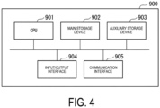
- FIG. 4 is a view illustrating an example of the hardware configuration of the system controller according to the embodiment.
- a computer 900 includes a CPU 901, a main storage device 902, an auxiliary storage device 903, an input/output interface 904, and a communication interface 905.
- the system controller 50 is implemented in the computer 900.
- the functions described above are stored in the auxiliary storage device 903 in a format of a program.
- the CPU 901 reads the program from the auxiliary storage device 903, develops the program to the main storage device 902, and executes the above-mentioned processing in accordance with the program.
- the CPU 901 secures a storage area in the main storage device 902 in compliance with the program.
- the CPU 901 secures a storage area for storing data under processing in the auxiliary storage device 903 in compliance with the program.
- a program for implementing all or some of the functions of the system controller 50 may be recorded in a computer-readable recording medium, and the program recorded in this recording medium may be read and executed by a computer system to perform processing by each functional unit.
- the "computer system” here includes hardware such as an operating system (OS) or peripheral equipment.
- OS operating system
- WWW world wide web
- the "computer system” also includes a home page providing environment (or a display environment).
- the "computer readable recording medium” refers to a portable medium such as a CD, a DVD, or a USB, or a storage device such as a hard disk built in a computer system.
- the computer 900 receiving the distribution may develop the program to the main storage device 902, and may execute the above-mentioned processing.
- the above-described program may implement part of the functions described above, and furthermore, also implement the functions described above in combination with a program already recorded in the computer system.
- the controller, the waste heat recovery refrigeration unit system, the control method, and the program described in each embodiment are grasped as follows, for example.
- a controller (system controller 50) is the controller of (1), in which when an outside temperature becomes equal to or higher than a predetermined first threshold temperature (first threshold temperature is temperature at which it can be determined not to be in the heating mode) or when the operation of the air conditioning unit is in a mode other than the heating mode, the heat recovery control unit controls the first waste heat recovery device 20 not to exchange heat with the first refrigerant and the second refrigerant.
- first threshold temperature is temperature at which it can be determined not to be in the heating mode
- the heat recovery control unit controls the first waste heat recovery device 20 not to exchange heat with the first refrigerant and the second refrigerant.
- the waste heat recovery device 20 When it can be determined not to be in the heating mode based on the outside temperature, the waste heat recovery device 20 is stopped. This can supply a large amount of waste heat to the hot-water supply unit 40.
- a controller (system controller 50) is the controller of (1) and (2), in which when an outside temperature becomes equal to or lower than a predetermined second threshold temperature, the heat recovery control unit controls the first waste heat recovery device and the second waste heat recovery device not to exchange heat with the first refrigerant.
- a controller (system controller 50) is the controller of (1) to (3), in which the waste heat recovery refrigeration unit system 100 further includes the heat source device 31 of the air conditioning unit 30, the water heater 41 of the hot-water supply unit 40, the first tank 33 that stores a heat medium whose temperature has been raised by the heat source device 31, and the second tank 44 that stores hot water whose temperature has been raised by the water heater 41, the controller further includes a heat source device control unit (air conditioning unit control unit 57) that controls the heat source device 31 and a water heater control unit (hot-water supply unit control unit 58) that controls the water heater 41, the heat source device control unit increases an operation load of the heat source device when an outside temperature becomes equal to or higher than a predetermined third threshold temperature (steps S28 and 29), and the water heater control unit increases an operation load of the water heater when an outside temperature becomes equal to or higher than a predetermined fourth threshold temperature (step S10).
- the waste heat recovery refrigeration unit system 100 further includes the heat source device 31 of the air conditioning unit 30, the water heater 41 of the hot-water
- a controller (system controller 50) is the controller of (1) to (4), in which the waste heat recovery refrigeration unit system further includes the first refrigeration unit and the second refrigeration unit, the controller further includes a first refrigeration unit control unit that controls the first refrigeration unit and a second refrigeration unit control unit that controls the second refrigeration unit, and when the hot-water supply unit or the air conditioning unit is not of a heat pump type, the first refrigeration unit control unit increases an operation load of the first refrigeration unit compared with an operation load when the refrigerating chamber is operated to cool the refrigerating chamber to a predetermined set temperature, and the second refrigeration unit control unit increases an operation load of the second refrigeration unit compared with an operation load when the freezing chamber is operated to cool the freezing chamber to a predetermined set temperature.
- the operation load of the refrigeration units 1a and 1b is increased to improve the operation efficiency of the waste heat recovery refrigeration unit system 100.
- the waste heat recovery refrigeration unit system 100 includes: a first refrigeration unit that cools a refrigerating chamber; a second refrigeration unit that cools the freezing chamber; an air conditioning unit; a hot-water supply unit; a first waste heat recovery device including a first heat exchange circuit that exchanges heat between a first refrigerant circulating through a first refrigerant circuit of the first refrigeration unit and a first water medium, a second heat exchange circuit that exchanges heat between a second refrigerant circulating through a second refrigerant circuit of the second refrigeration unit and the first water medium, a circuit that supplies heat of the first water medium subjected to heat exchange to the air conditioning unit, a valve that is provided in the first heat exchange circuit and switches whether the first water medium flows through the first heat exchange circuit, and a valve that is provided in the second heat exchange circuit and switches whether the first water medium flows through the second heat exchange circuit; a second waste heat recovery device including a third heat exchange circuit that exchanges heat between the first refrigerant and a second
- a control method is a control method of a waste heat recovery refrigeration unit system including a first waste heat recovery device that recovers heat by exchanging heat with a first refrigerant circulating through a refrigerant circuit of a first refrigeration unit that cools a refrigerating chamber and/or a second refrigerant circulating through a refrigerant circuit of a second refrigeration unit that cools a freezing chamber, and supplies, to an air conditioning unit, the heat having been recovered, and a second waste heat recovery device that recovers heat by exchanging heat with the first refrigerant and/or the second refrigerant, and supplies, to a hot-water supply unit, the heat having been recovered, the waste heat recovery refrigeration unit system being configured such that the first waste heat recovery device can switch whether to exchange heat with each of the first refrigerant and the second refrigerant, and the second waste heat recovery device can switch whether to exchange heat with each of the first refrigerant and the second refrigerant, the control method including controlling whether each of the first waste heat recovery device
- a program causes a computer to execute a control method of a waste heat recovery refrigeration unit system including a first waste heat recovery device that recovers heat by exchanging heat with a first refrigerant circulating through a refrigerant circuit of a first refrigeration unit that cools a refrigerating chamber and/or a second refrigerant circulating through a refrigerant circuit of a second refrigeration unit that cools a freezing chamber, and supplies, to an air conditioning unit, the heat having been recovered, and a second waste heat recovery device that recovers heat by exchanging heat with the first refrigerant and/or the second refrigerant, and supplies, to a hot-water supply unit, the heat having been recovered, the waste heat recovery refrigeration unit system being configured such that the first waste heat recovery device can switch whether to exchange heat with each of the first refrigerant and the second refrigerant, and the second waste heat recovery device can switch whether to exchange heat with each of the first refrigerant and the second refrigerant, the processing being processing of controlling whether
Landscapes
- Engineering & Computer Science (AREA)
- Physics & Mathematics (AREA)
- Mechanical Engineering (AREA)
- Thermal Sciences (AREA)
- General Engineering & Computer Science (AREA)
- Chemical & Material Sciences (AREA)
- Combustion & Propulsion (AREA)
- Other Air-Conditioning Systems (AREA)
- Air Conditioning Control Device (AREA)
- Heat-Pump Type And Storage Water Heaters (AREA)
Abstract
Description
- The present invention relates to a controller, a waste heat recovery refrigeration unit system, a control method, and a program.
-
Patent Document 1 discloses a heat pump system including a refrigeration unit including a variable capacity compressor and an evaporator, a water medium circuit that recovers waste heat of a refrigerant circuit by exchanging heat with a refrigerant circulating through the refrigerant circuit of the refrigeration unit, and an auxiliary heat source that heats a water medium circulating through the water medium circuit, and control of causing the auxiliary heat source to perform operation when a difference between an outlet temperature of the water medium in the refrigerant-water heat exchanger and a target outlet temperature is equal to or greater than a threshold value in the heat pump system. According to the heat pump system disclosed inPatent Document 1, waste heat of the refrigerant circuit recovered by the water medium circuit can be supplied to loads such as heating and hot-water supply. -
Patent Document 1 mentions operation in which a refrigeration unit and a water heater or a refrigeration unit and heating are combined, but does not mention a condition under which use of waste heat of a refrigeration unit for operation of heating, hot-water supply, or the like allows operation of the entire system including the refrigeration unit and the heating to be made efficient. - Patent Document 1:
Japanese Patent No. 5400177 - There is a demand for a method for improving the overall efficiency of a system including a refrigeration unit and a loading device (an air conditioner, a water heater, or the like) utilizing its waste heat.
- Therefore, an object of the present invention is to provide a controller, a waste heat recovery refrigeration unit system, a control method, and a program that can solve the above-described problems.
- According to one aspect of the present disclosure, a controller is a controller of a waste heat recovery refrigeration unit system including a first waste heat recovery device that recovers heat by exchanging heat with a first refrigerant circulating through a refrigerant circuit of a first refrigeration unit that cools a refrigerating chamber and/or a second refrigerant circulating through a refrigerant circuit of a second refrigeration unit that cools a freezing chamber, and supplies, to an air conditioning unit, the heat having been recovered, and a second waste heat recovery device that recovers heat by exchanging heat with the first refrigerant and/or the second refrigerant, and supplies, to a hot-water supply unit, the heat having been recovered, the waste heat recovery refrigeration unit system being configured such that the first waste heat recovery device can switch whether to exchange heat with each of the first refrigerant and the second refrigerant, and the second waste heat recovery device can switch whether to exchange heat with each of the first refrigerant and the second refrigerant, the controller including a heat recovery control unit that controls whether each of the first waste heat recovery device and the second waste heat recovery device exchanges heat with the first refrigerant and whether each of the first waste heat recovery device and the second waste heat recovery device exchanges heat with the second refrigerant, according to an outside temperature.
- According to one aspect of the present disclosure, a waste heat recovery refrigeration unit system includes: a first refrigeration unit that cools a refrigerating chamber; a second refrigeration unit that cools the freezing chamber; an air conditioning unit; a hot-water supply unit; a first waste heat recovery device including a first heat exchange circuit that exchanges heat between a first refrigerant circulating through a first refrigerant circuit of the first refrigeration unit and a first water medium, a second heat exchange circuit that exchanges heat between a second refrigerant circulating through a second refrigerant circuit of the second refrigeration unit and the first water medium, a circuit that supplies heat of the first water medium subjected to heat exchange to the air conditioning unit, a valve that is provided in the first heat exchange circuit and switches whether the first water medium flows through the first heat exchange circuit, and a valve that is provided in the second heat exchange circuit and switches whether the first water medium flows through the second heat exchange circuit; a second waste heat recovery device including a third heat exchange circuit that exchanges heat between the first refrigerant and a second water medium, a fourth heat exchange circuit that exchanges heat between the second refrigerant and the second water medium, a circuit that supplies heat of the second water medium subjected to heat exchange to the hot-water supply unit, a valve that is provided in the third heat exchange circuit and switches whether the second water medium flows through the third heat exchange circuit, and a valve that is provided in the fourth heat exchange circuit and switches whether the second water medium flows through the fourth heat exchange circuit; and the controller according to any one of
claims 1 to 5. - According to one aspect of the present disclosure, a control method is a control method of a waste heat recovery refrigeration unit system including a first waste heat recovery device that recovers heat by exchanging heat with a first refrigerant circulating through a refrigerant circuit of a first refrigeration unit that cools a refrigerating chamber and/or a second refrigerant circulating through a refrigerant circuit of a second refrigeration unit that cools a freezing chamber, and supplies, to an air conditioning unit, the heat having been recovered, and a second waste heat recovery device that recovers heat by exchanging heat with the first refrigerant and/or the second refrigerant, and supplies, to a hot-water supply unit, the heat having been recovered, the waste heat recovery refrigeration unit system being configured such that the first waste heat recovery device can switch whether to exchange heat with each of the first refrigerant and the second refrigerant, and the second waste heat recovery device can switch whether to exchange heat with each of the first refrigerant and the second refrigerant, the control method including controlling whether each of the first waste heat recovery device and the second waste heat recovery device exchanges heat with the first refrigerant and whether each of the first waste heat recovery device and the second waste heat recovery device exchanges heat with the second refrigerant, according to an outside temperature.
- According to one aspect of the present disclosure, a program causes a computer to execute processing of a control method of a waste heat recovery refrigeration unit system including a first waste heat recovery device that recovers heat by exchanging heat with a first refrigerant circulating through a refrigerant circuit of a first refrigeration unit that cools a refrigerating chamber and/or a second refrigerant circulating through a refrigerant circuit of a second refrigeration unit that cools a freezing chamber, and supplies, to an air conditioning unit, the heat having been recovered, and a second waste heat recovery device that recovers heat by exchanging heat with the first refrigerant and/or the second refrigerant, and supplies, to a hot-water supply unit, the heat having been recovered, the waste heat recovery refrigeration unit system being configured such that the first waste heat recovery device can switch whether to exchange heat with each of the first refrigerant and the second refrigerant, and the second waste heat recovery device can switch whether to exchange heat with each of the first refrigerant and the second refrigerant, the processing being processing of controlling whether each of the first waste heat recovery device and the second waste heat recovery device exchanges heat with the first refrigerant and whether each of the first waste heat recovery device and the second waste heat recovery device exchanges heat with the second refrigerant, according to an outside temperature.
- According to the controller, the waste heat recovery refrigeration unit system, the control method, and the program of the present disclosure, the overall operation efficiency of a system including a refrigeration unit and a loading device can be improved utilizing its waste heat.
-
-
FIG. 1 is a view illustrating an example of a waste heat recovery refrigeration unit system according to an embodiment. -
FIG. 2 is a view illustrating an example of a system controller according to the embodiment. -
FIG. 3A is a first flowchart showing an example of waste heat recovery control according to the embodiment. -
FIG. 3B is a second flowchart showing an example of waste heat recovery control according to the embodiment. -
FIG. 4 is a view illustrating an example of a hardware configuration of the system controller according to the embodiment. - Hereinafter, a waste heat recovery refrigeration unit system according to one embodiment of the present disclosure will be described with reference to
FIGS. 1 to 4 . -
FIG. 1 is a view illustrating an example of the waste heat recovery refrigeration unit system according to the embodiment. A waste heat recoveryrefrigeration unit system 100 is used in a store such as a supermarket, and includes arefrigeration unit 1a that cools a refrigerated showcase, arefrigeration unit 1b that cools a freezer showcase, anair conditioning unit 30, a hot-water supply unit 40, a wasteheat recovery device 10 that recovers waste heat of therefrigeration unit 1a and therefrigeration unit 1b and supplies the waste heat to the hot-water supply unit 40 of the store, a wasteheat recovery device 20 that recovers waste heat of therefrigeration unit 1a and therefrigeration unit 1b and supplies the waste heat to theair conditioning unit 30 of the store, asystem controller 50, andtemperature sensors 60a to 60d. Thetemperature sensors 60a to 60d measure outside temperatures. The outside temperature is an ambient temperature of a site where each device of therefrigeration units air conditioning unit 30, and awater heater 41 is installed. Thetemperature sensor 60a is provided near the installation site of therefrigeration unit 1a and measures the ambient temperature of therefrigeration unit 1a. Thetemperature sensor 60b is provided near the installation site of therefrigeration unit 1b and measures the ambient temperature of therefrigeration unit 1b. Thetemperature sensor 60c is provided near an installation site of an air conditioner not illustrated and measures the ambient temperature of the air conditioner. Thetemperature sensor 60d is provided near the installation site of thewater heater 41 and measures the ambient temperature of thewater heater 41. The outside temperature measured by thetemperature sensor 60a is transmitted to acontrol unit 7a and thesystem controller 50. The outside temperature measured by thetemperature sensor 60b is transmitted to acontrol unit 7b and thesystem controller 50. The outside temperature measured by thetemperature sensor 60c is transmitted to acontrol unit 35 and thesystem controller 50. The outside temperature measured by thetemperature sensor 60d is transmitted to acontrol unit 46 and thesystem controller 50. - The
refrigeration unit 1a includes acompressor 2a, agas cooler 3a, anexpansion valve 4a, anevaporator 5a, arefrigerant pipe 6a connecting them, and thecontrol unit 7a. Thecompressor 2a compresses and discharges the refrigerant. Aheat exchanger 11a of the wasteheat recovery device 10 and aheat exchanger 21a of the wasteheat recovery device 20 are connected (inserted) between thecompressor 2a and thegas cooler 3a, and the refrigerant of therefrigeration unit 1a flows through theheat exchanger 11a and theheat exchanger 21a. In theheat exchanger 11a, heat of the high-temperature and high-pressure refrigerant is recovered by the refrigerant (water) in the wasteheat recovery device 10 and supplied to the hot-water supply unit 40. In theheat exchanger 21a, heat of the high-temperature and high-pressure refrigerant is recovered by the refrigerant (water) of the wasteheat recovery device 20 and supplied to theair conditioning unit 30. The refrigerant that has passed through theheat exchanger 11a and theheat exchanger 21a exchanges heat with air in thegas cooler 3a to radiate heat, and is condensed. The condensed refrigerant is decompressed and expanded by theexpansion valve 4a and supplied to theevaporator 5a. The refrigerant supplied to theevaporator 5a absorbs heat of the refrigerated showcase to cool air in the refrigerated showcase. The refrigerant vaporized in theevaporator 5a is sucked into thecompressor 2a. The refrigerant is compressed by thecompressor 2a and circulates through the above path again. As the refrigerant of therefrigeration unit 1a, for example, CO2 is used. The CO2 refrigerant enters a supercritical state in a normal temperature range of about 31 °C. When the outside temperature measured by thetemperature sensor 60a becomes equal to or greater than a predetermined threshold value, or when heat is recovered by the wasteheat recovery device 10 or the wasteheat recovery device 20, thecontrol unit 7a operates in a state where the CO2 refrigerant becomes supercritical at high pressure, and otherwise operates in a state where the high pressure becomes subcritical. - The
refrigeration unit 1b includes acompressor 2b, agas cooler 3b, anexpansion valve 4b, anevaporator 5b, arefrigerant pipe 6b connecting them, and thecontrol unit 7b. Thecompressor 2b compresses and discharges the refrigerant. Aheat exchanger 11b of the wasteheat recovery device 10 and aheat exchanger 21b of the wasteheat recovery device 20 are connected (inserted) between thecompressor 2b and thegas cooler 3b, and the refrigerant of therefrigeration unit 1b flows through theheat exchanger 11b and theheat exchanger 21b. In theheat exchanger 11b, heat of the high-temperature and high-pressure refrigerant is recovered by the refrigerant (water) in the wasteheat recovery device 10 and supplied to the hot-water supply unit 40. In theheat exchanger 21b, heat of the high-temperature and high-pressure refrigerant is recovered by the refrigerant (water) of the wasteheat recovery device 20 and supplied to theair conditioning unit 30. The refrigerant that has passed through theheat exchanger 11b and theheat exchanger 21b exchanges heat with air in thegas cooler 3b to radiate heat, and is condensed. The condensed refrigerant is decompressed and expanded by theexpansion valve 4b and supplied to theevaporator 5b. The refrigerant supplied to theevaporator 5b absorbs heat of the freezer showcase to cool air in the freezer showcase. The refrigerant vaporized in theevaporator 5b is sucked into thecompressor 2b. The CO2 refrigerant is compressed by thecompressor 2b and circulates through the above path again. As the refrigerant of therefrigeration unit 1b, for example, CO2 is used. When the outside temperature measured by thetemperature sensor 60b becomes equal to or greater than a predetermined threshold value, thecontrol unit 7b operates in a state where the CO2 refrigerant becomes supercritical at high pressure, and otherwise operates in a state where the high pressure becomes subcritical. Similarly to the case of therefrigeration unit 1a, when heat is recovered by the wasteheat recovery device 10 or the wasteheat recovery device 20, thecontrol unit 7b may operate in a state of supercritical at high pressure regardless of the outside temperature measured by thetemperature sensor 60b. Comparing therefrigeration units refrigeration unit 1a, and the refrigerant temperature at high pressure is higher in therefrigeration unit 1b. - The waste
heat recovery device 10 includes theheat exchanger 11a, theheat exchanger 11b, apump 13, aheat exchanger 14, apipe 15a that branches from apipe 15b and is connected to theheat exchanger 11a on an upstream side in the flow direction of a water medium relative to theheat exchanger 11b and is connected to thepipe 15b on a downstream side in the flow direction of the water medium of theheat exchanger 11b, avalve 12a provided in thepipe 15a, thepipe 15b connecting theheat exchanger 11b, thepump 13, and theheat exchanger 14 and allowing the water medium to circulate among them, avalve 12b provided between a branching point to thepipe 15a on the upstream side in the flow direction of the water medium of thepipe 15b and theheat exchanger 11b, and acontrol unit 16. Thecontrol unit 16 controls start and stop of thepump 13 and open and close of thevalve 12a and the valve 12b. (1) When thepump 13 is started, thevalve 12a enters an open state, and thevalve 12b enters a close state, the water medium circulates through thepipe 15a, and absorbs heat from the CO2 refrigerant of therefrigeration unit 1a in theheat exchanger 11a, so that the temperature of the water medium increases. The water medium with risen temperature flows through thepipe 15a, merges to thepipe 15b, flows through thepipe 15b to reach theheat exchanger 14, and in theheat exchanger 14, heat is exchanged between the water medium flowing through thepipe 15b and the water medium on the hot-water supply unit 40 side to raise the temperature of the water medium on the hot-water supply unit 40 side. (2) When thepump 13 is started, thevalve 12a enters a close state, and thevalve 12b enters an open state, the water medium circulates through thepipe 15b, and absorbs heat from the CO2 refrigerant of therefrigeration unit 1b in theheat exchanger 11b, so that the temperature of the water medium increases. The water medium with risen temperature flows through thepipe 15b to reach theheat exchanger 14, and in theheat exchanger 14, heat is exchanged between the water medium flowing through thepipe 15b and the water medium on the hot-water supply unit 40 side to raise the temperature of the water medium on the hot-water supply unit 40 side. (3) When thepump 13 is started, thevalve 12a enters an open state, and thevalve 12b enters an open state, heat is exchanged in both theheat exchanger 11a and theheat exchanger 11b, the temperature of the water medium flowing through the wasteheat recovery device 10 rises, and the temperature of the water medium on the hot-water supply unit 40 side is raised in theheat exchanger 14. - The waste
heat recovery device 20 includes theheat exchanger 21a, theheat exchanger 21b, apump 23, apipe 24b that branches from apipe 24a and is connected to theheat exchanger 21b on an upstream side in the flow direction of the water medium relative to theheat exchanger 21a and is connected to thepipe 24a on a downstream side in the flow direction of the water medium of theheat exchanger 21a, avalve 22b provided on thepipe 24b, thepipe 24a connecting theheat exchanger 21a, thepump 23, and theair conditioning unit 30 side and allowing the water medium to circulate among them, avalve 22a provided between a branching point to thepipe 24b on the upstream side in the flow direction of the water medium of thepipe 24a and theheat exchanger 21a, and acontrol unit 25. Thecontrol unit 25 controls start and stop of thepump 23 and open and close of thevalve 22a and the valve 22b. (1) When thepump 23 is started, thevalve 22a enters an open state, and thevalve 22b enters a close state, the water medium circulates through thepipe 24a and theair conditioning unit 30, and absorbs heat from the CO2 refrigerant of therefrigeration unit 1a in theheat exchanger 21a, so that the temperature of the water medium increases. The water medium with risen temperature flows through thepipe 24a to reach atank 33 of theair conditioning unit 30, the hot water in thetank 33 is supplied to the air conditioner not illustrated, and the water returning from the air conditioner reaches atank 32. Thepump 23 of the wasteheat recovery device 20 sucks water from thetank 32 of theair conditioning unit 30 and sends the water to the heat exchanger 21a. (2) When thepump 23 is started, thevalve 22a enters a close state, and thevalve 22b enters an open state, the water medium reaches theheat exchanger 21b through thepipe 24b, and absorbs heat from the CO2 refrigerant of therefrigeration unit 1b in theheat exchanger 21b, so that the temperature of the water medium increases. The water medium with risen temperature flows through thepipe 24b, merges with thepipe 24a, reaches thetank 33 of theair conditioning unit 30, and is supplied to the air conditioner not illustrated. Thepump 23 sucks water from thetank 32 and sends the water to the heat exchanger 21b. (3) When thepump 23 is started, thevalve 22a enters an open state, and thevalve 22b enters an open state, heat is exchanged in both theheat exchanger 21a and theheat exchanger 21b, the temperature of the water medium flowing through the wasteheat recovery device 20 rises, and the water medium is supplied to thetank 33 and used for air conditioning. The water after being used is sent to thetank 32, and in the wasteheat recovery device 20, the water in thetank 32 is sent to theheat exchanger 21a and/or theheat exchanger 21b, and the waste heat of therefrigeration units - The
air conditioning unit 30 includes aheat source device 31 for air conditioning, thetank 32, thetank 33, a pump 34, and thecontrol unit 35. Theheat source device 31 and thetank 32 are connected via apipe 352. Theheat source device 31 and thetank 33 are connected via a pipe 353. Thetank 33 is connected to the air conditioner not illustrated via apipe 354, and by driving of the pump 34 provided in thepipe 354, the hot water in thetank 33 is supplied to the air conditioner not illustrated. Thecontrol unit 35 controls theheat source device 31 and the pump 34. Thecontrol unit 35 acquires and stores information on the amount and temperature of the hot water stored in thetank 33 and the heat storage amount. For example, atemperature sensor 331 and aflow rate sensor 332 are provided in the flow path on thetank 33 inlet side of the water medium supplied from the wasteheat recovery device 20. A temperature sensor 333 and a flow rate sensor 334 are provided in the flow path on thetank 33 inlet side of the water medium supplied from theheat source device 31. Atemperature sensor 335 and aflow rate sensor 336 are provided in the flow path on thetank 33 outlet side of the hot water to be supplied to the air conditioner not illustrated. Atemperature sensor 321 is provided in the flow path from thetank 32 to thepump 23, atemperature sensor 322 is provided in the flow path from thetank 32 to theheat source device 31, and atemperature sensor 351a is provided in the flow path of apipe 351. Thecontrol unit 35 acquires the temperatures measured by thetemperature sensors flow rate sensors control unit 35 acquires and stores the temperature measured by thetemperature sensor 335 at each time as information on the temperature of the hot water stored in thetank 33. Thecontrol unit 35 acquires and stores, as information on the amount of hot water stored in thetank 33, a value obtained by temporally adding a value obtained by subtracting the flow rate measured by theflow rate sensor 336 from the sum of the flow rate measured by theflow rate sensor 332 and the flow rate measured by the flow rate sensor 334 at each time. Thecontrol unit 35 calculates the waste heat recovery amount by (temperature measured by thetemperature sensor 331 at each time - temperature measured by thetemperature sensor 321 at each time) × flow rate measured by theflow rate sensor 332 at each time, and calculates the output from theheat source device 31 by (temperature measured by the temperature sensor 333 at each time - temperature measured by thetemperature sensor 322 at each time) × flow rate measured by the flow rate sensor 334 at each time. Thecontrol unit 35 calculates the amount of heat actually consumed on the load side by (temperature measured by thetemperature sensor 335 at each time - temperature measured by thetemperature sensor 351a at each time) × flow rate measured by theflow rate sensor 336 at each time. Thecontrol unit 35 calculates the heat storage amount of thetank 33 by temporally adding a value obtained by subtracting the amount of heat actually consumed on the load side from the sum of the calculated waste heat recovery amount and the output from theheat source device 31. Thecontrol unit 35 operates theheat source device 31 according to an operation mode (cooling, heating, stopping, and the like) or the load of the air conditioner. For example, when the air conditioner is in a heating mode, theheat source device 31 heats the water in thetank 32 and supplies the hot water after heated to thetank 33. Hot water generated by theheat source device 31 and hot water whose heat is recovered by the wasteheat recovery device 20 are supplied to thetank 33. The hot water in thetank 33 is supplied to the air conditioner not illustrated, releases heat by a fan coil unit or the like of the air conditioner, and the water medium having a low temperature is returned to thetank 32 through thepipe 351. The temperature of the water medium returned to thetank 32 is raised by theheat source device 31 and the wasteheat recovery device 20, and the hot water after the temperature rise is stored in thetank 33. Thecontrol unit 35 adjusts the operation load of theheat source device 31 according to the amount and temperature of the hot water stored in thetank 33. For example, even when the set temperature of heating is the same, theheat source device 31 is operated at a high load when the amount of hot water stored in thetank 33 is small as compared with the case where the heat storage amount of thetank 33 is large, and theheat source device 31 is operated with the load reduced (heat storage is used) when the heat storage amount of thetank 33 is large. When the outside temperature measured by thetemperature sensor 60c is high, theheat source device 31 can be operated at a load higher than the load required by the air conditioner to generate a large amount of high-temperature water medium and store excess hot water in thetank 33. The stored hot water is used, for example, when the outside temperature decreases. This can reduce the operation load on theheat source device 31 when the outside temperature decreases. For example, by operating with a slightly increased load while the outside temperature during the day is high (while the operation load is low) to store excess heat, and using the heat stored in the heating of the store after the evening, it is possible to improve the operation efficiency during a predetermined period (for example, one day). - The hot-
water supply unit 40 includes thewater heater 41, a three-way valve 42, a three-way valve 43, a tank 44, apump 45, and acontrol unit 46. The three-way valve 42 is connected to apipe 451, a pipe 452, and apipe 454 for water supply. The pipe 452 connects the three-way valve 42 and the tank 44, and theheat exchanger 14 of the wasteheat recovery device 10 is provided in the middle thereof. Thepipe 454 connects the three-way valve 42 and thewater heater 41. Apipe 453 branches from thepipe 454, and thepipe 453 connects the branching point of thepipe 454 and the three-way valve 43. Thepipe 456 connects the tank 44 and the three-way valve 43. A remaining port of the three-way valve 43 is connected to apipe 457 for supplying hot water. Thewater heater 41 and the tank 44 are connected by apipe 455. Tap water supplied through thepipe 451 is divided by the three-way valve 42 and supplied to thewater heater 41 through thepipe 454. Thewater heater 41 boils the tap water, and supplies the hot water to the tank 44 through thepipe 455. On the other hand, the tap water divided by the three-way valve 42 and sent to the pipe 452 exchanges heat with the water refrigerant flowing through the wasteheat recovery device 10 in theheat exchanger 14 to absorb heat, and is sent to the tank 44. Hot water generated by thewater heater 41 and hot water with heat recovered by the wasteheat recovery device 10 are supplied to the tank 44. The hot water stored in the tank 44 flows through thepipe 456, is mixed with tap water supplied through thepipe 453 at the three-way valve 43, and is then supplied to equipment using hot water through thepipe 457. Thepipe 457 is provided with thepump 45, and the hot water is supplied to the load side by driving of thepump 45. Thecontrol unit 46 operates thewater heater 41 and stores the hot water in the tank 44 according to a demand for hot water. Thecontrol unit 46 acquires and stores information on the amount and temperature of the hot water stored in the tank 44 and the heat storage amount. Atemperature sensor 441 and aflow rate sensor 442 are provided in the flow path on the tank 44 inlet side of the water medium subjected to heat exchange in theheat exchanger 14 of the wasteheat recovery device 10, for example. Atemperature sensor 443 and aflow rate sensor 444 are provided in the flow path on the tank 44 inlet side of the water medium supplied from thewater heater 41. Atemperature sensor 445 and aflow rate sensor 446 are provided in the flow path on the hot water outlet side of the tank 44. Thecontrol unit 46 acquires the temperatures measured by thetemperature sensors flow rate sensors control unit 46 acquires and stores the temperature measured by thetemperature sensor 445 at each time as information on the temperature of the hot water stored in the tank 44. Thecontrol unit 46 acquires and stores, as information on the amount of hot water stored in the tank 44, a value obtained by temporally adding a value obtained by subtracting the flow rate measured by theflow rate sensor 446 from the sum of the flow rate measured by theflow rate sensor 442 and the flow rate measured by theflow rate sensor 444 at each time. Thecontrol unit 46 calculates the heat storage amount of the tank 44 by temporally adding a value obtained by multiplying a value obtained by subtracting the flow rate measured by theflow rate sensor 446 from the sum of the flow rate measured by theflow rate sensor 442 and the flow rate measured by theflow rate sensor 444 at each time by a temperature difference between a predetermined reference temperature and the temperature measured by thetemperature sensor 445. Thecontrol unit 46 adjusts an operation load of thewater heater 41 according to the amount, temperature, and heat storage amount of the hot water stored in the tank 44. For example, when hot water with temperature raised by theheat exchanger 14 is supplied to the tank 44, thecontrol unit 46 reduces the load on thewater heater 41 according to the heat storage amount of the hot water with heat recovered by the waste heat recovery device 10 (heat storage is used). For example, when the outside temperature measured by thetemperature sensor 60d is high, thewater heater 41 can be operated at a load higher than a required load to generate a large amount of hot water and store excess hot water in the tank 44. The stored hot water is used when there is a large demand for hot water or when the outside temperature or the water temperature measured by thetemperature sensor 60d is low. This can reduce the operation load on thewater heater 41 at the time of high load. - The waste heat recovery
refrigeration unit system 100 illustrated inFIG. 1 schematically illustrates a basic configuration, and may further include other constituent elements. For example, inFIG. 1 , theheat exchangers refrigeration units air conditioning unit 30 and the hot-water supply unit 40, but a plurality of heat exchangers may be incorporated in for each of therefrigeration units -
FIG. 2 is a view illustrating an example of the system controller according to the embodiment. Thesystem controller 50 is connected to thecontrol units FIG. 1 . Thesystem controller 50 communicates with thecontrol units refrigeration units heat recovery devices air conditioning unit 30, and the hot-water supply unit 40 so as to improve the efficiency of the entire waste heat recoveryrefrigeration unit system 100. Thesystem controller 50 includes an outsidetemperature acquisition unit 51, adetermination unit 52, a first refrigerationunit control unit 53, a second refrigerationunit control unit 54, a first heatrecovery control unit 55, a second heatrecovery control unit 56, an air conditioningunit control unit 57, a hot-water supplyunit control unit 58, and a storage andmemory unit 59. - The outside
temperature acquisition unit 51 acquires the outside temperature measured by each of thetemperature sensors 60a to 60d. - The
determination unit 52 makes a determination related to the waste heat recovery control from therefrigeration units refrigeration units refrigeration unit system 100. To improve the operation efficiency is, for example, to operate while reducing the energy consumption of the waste heat recoveryrefrigeration unit system 100 as much as possible. For example, in a case where therefrigeration units temperature sensor 60a or the like is equal to or higher than X1 °C, and in a case where the efficiency of the entire system can be improved by using the waste heat of therefrigeration units air conditioning unit 30 and the hot-water supply unit 40 without operating the wasteheat recovery devices determination unit 52 determines operating the wasteheat recovery devices FIGS. 3A and3B . Thedetermination unit 52 acquires information regarding the state of each device acquired from thecontrol units unit control unit 53, the second refrigerationunit control unit 54, the first heatrecovery control unit 55, the second heatrecovery control unit 56, the air conditioningunit control unit 57, and the hot-water supplyunit control unit 58, and makes those determinations. - The first refrigeration
unit control unit 53 communicates with thecontrol unit 7a of therefrigeration unit 1a to acquire the operation mode of therefrigeration unit 1a. The first refrigerationunit control unit 53 instructs the operation mode of therefrigeration unit 1a to thecontrol unit 7a. For example, in a case where the loads of theair conditioning unit 30 and the hot-water supply unit 40 are high and the efficiency of the entire waste heat recoveryrefrigeration unit system 100 is improved rather by increasing the waste heat recovery amount, the first refrigerationunit control unit 53 instructs thecontrol unit 7a to increase the operation load. Upon instruction to increase the operation load, thecontrol unit 7a increases the rotation speed of thecompressor 2a and increases the discharge temperature of the CO2 refrigerant so as to increase the amounts of heat exchange in theheat exchangers - The second refrigeration
unit control unit 54 communicates with thecontrol unit 7b of therefrigeration unit 1b to acquire the operation mode of therefrigeration unit 1b. The second refrigerationunit control unit 54 instructs the operation mode of therefrigeration unit 1b to thecontrol unit 7b. For example, in a case where the loads of theair conditioning unit 30 and the hot-water supply unit 40 are high and the efficiency of the entire waste heat recoveryrefrigeration unit system 100 is improved rather by increasing the waste heat recovery amount, the second refrigerationunit control unit 54 instructs thecontrol unit 7b to increase the operation load. Upon instruction to increase the operation load, thecontrol unit 7b increases the rotation speed of thecompressor 2a and increases the discharge temperature of the CO2 refrigerant so as to increase the amounts of heat exchange in theheat exchangers - The first heat
recovery control unit 55 communicates with thecontrol unit 16 of the wasteheat recovery device 10 to acquire information regarding an operation state of the wasteheat recovery device 10, for example, whether thepump 13 is activated or stopped, whethervalves pump 13 reaches a target temperature. The first heatrecovery control unit 55 controls the operation of the wasteheat recovery device 10. For example, when the hot-water supply unit 40 is stopped and there is no need to supply the waste heat of therefrigeration units recovery control unit 55 instructs thecontrol unit 16 to stop thepump 13. Thecontrol unit 16 stops thepump 13 based on this instruction. For example, when the waste heat of therefrigeration unit 1a for refrigeration is not supplied to the hot-water supply unit 40, the first heatrecovery control unit 55 instructs thecontrol unit 16 to stop the waste heat recovery from therefrigeration unit 1a. Based on this instruction, thecontrol unit 16 controls thepump 13 to be in an operating state, thevalve 12a to be in a close state, and thevalve 12b to be in an open state. For example, when the temperature of the water refrigerant is lower than the target temperature, the first heatrecovery control unit 55 instructs an increase in the rotation speed of thepump 13, and thecontrol unit 16 controls thepump 13 based on this instruction. - The second heat
recovery control unit 56 communicates with thecontrol unit 25 of the wasteheat recovery device 20 to acquire information regarding an operation state of the wasteheat recovery device 20, for example, whether thepump 23 is activated or stopped, whethervalves pump 23 reaches a target temperature. The second heatrecovery control unit 56 controls the operation of the wasteheat recovery device 20. For example, when there is no need to supply the waste heat of therefrigeration units air conditioning unit 30 is stopped or performing cooling operation, the second heatrecovery control unit 56 instructs thecontrol unit 25 to stop thepump 23. Thecontrol unit 25 stops thepump 23 based on this instruction. For example, when the waste heat of therefrigeration unit 1a for refrigeration is not supplied to theair conditioning unit 30, the second heatrecovery control unit 56 instructs thecontrol unit 25 to stop the waste heat recovery from therefrigeration unit 1a. Based on this instruction, thecontrol unit 25 controls thepump 23 to be in an operating state, thevalve 22a to be in a close state, and thevalve 22b to be in an open state. For example, when the temperature of the water refrigerant is lower than the target temperature, the second heatrecovery control unit 56 instructs an increase in the rotation speed of thepump 23, and thecontrol unit 25 controls thepump 23 based on this instruction. - The air conditioning
unit control unit 57 communicates with thecontrol unit 35 to acquire information regarding an operation state of theair conditioning unit 30, for example, whether theair conditioning unit 30 is performing the cooling operation, performing the heating operation, stopped, performing an operation using the recovered waste heat, performing an operation for heat storage, and the water temperature and the water amount of thetank 33. The air conditioningunit control unit 57 controls theair conditioning unit 30. For example, when the outside temperature measured by thetemperature sensor 60c is high, the air conditioningunit control unit 57 instructs thecontrol unit 35 to store heat to thetank 33 in addition to the response to the air conditioning load. For example, the air conditioningunit control unit 57 instructs thecontrol unit 35 to perform the operation using the waste heat recovered by the wasteheat recovery device 20. For example, in theair conditioning unit 30, a control method in a case of utilizing waste heat is determined in advance, and thecontrol unit 35 executes an operation using the waste heat based on this control method. - The hot-water supply
unit control unit 58 communicates with thecontrol unit 46 to acquire information regarding an operation state of the hot-water supply unit 40, for example, whether the hot-water supply unit 40 is operating, stopped, performing an operation using waste heat, performing an operation for heat storage, and the water temperature and the water amount of the tank 44. The hot-water supplyunit control unit 58 controls the hot-water supply unit 40. For example, when the outside temperature measured by thetemperature sensor 60d is high, the hot-water supplyunit control unit 58 instructs thecontrol unit 46 to store heat to the tank 44 in addition to the response to the hot-water supply load. For example, the hot-water supplyunit control unit 58 instructs thecontrol unit 46 to perform the operation utilizing the waste heat recovered by the wasteheat recovery device 10. For example, in the hot-water supply unit 40, a control method for using waste heat is determined in advance, and thecontrol unit 46 executes an operation using the waste heat based on this control method. - The storage and
memory unit 59 stores the outside temperatures measured by thetemperature sensors 60a to 60d acquired by the outsidetemperature acquisition unit 51, various programs that exhibit functions of thesystem controller 50, determination conditions used by thedetermination unit 52, processing process data, and the like. - Next, an example of waste heat recovery control for improving the efficiency of the entire waste heat recovery
refrigeration unit system 100 will be described with reference toFIGS. 3A and3B . -
FIG. 3A is a first flowchart showing an example of the waste heat recovery control according to the embodiment. - First, the
determination unit 52 determines whether the model of thewater heater 41 is a heat pump type (step S1). The heat pumptype water heater 41 originally has high operation efficiency. On the other hand, when thewater heater 41 is an electric heating wire unit driven by electricity, a boiler using fossil fuel, or the like, the operation efficiency tends to be lower than that of the heat pumptype water heater 41. In the case of thewater heater 41 other than the heat pump type, there is a case where the overall system efficiency is improved by increasing the operation load of therefrigeration units water heater 41 rather than covering all the loads by thewater heater 41 with poor efficiency. Step S1 is a determination condition based on such an idea. If the model of thewater heater 41 is not the heat pump type (step S1; No), thedetermination unit 52 determines use of the waste heat of therefrigeration unit 1a for refrigeration, use of the waste heat of therefrigeration unit 1b for freezing, and operation of thewater heater 41 according to the load (step S9). Based on the determination of thedetermination unit 52, the first heatrecovery control unit 55 instructs thecontrol unit 16 to activate thepump 13 and bring thevalve 12a and thevalve 12b into an open state. Thecontrol unit 16 activates thepump 13 and brings thevalve 12a and thevalve 12b into an open state. Based on the determination of thedetermination unit 52, the hot-water supplyunit control unit 58 instructs thecontrol unit 46 to perform the operation utilizing the waste heat recovered by the wasteheat recovery device 10. Thecontrol unit 46 operates thewater heater 41 in the instructed mode. The first refrigerationunit control unit 53 instructs thecontrol unit 7a to increase the operation load of therefrigeration unit 1a. Thecontrol unit 7a increases the rotation speed of thecompressor 2a to increase the discharge temperature and the discharge pressure of the refrigerant. The second refrigerationunit control unit 54 instructs thecontrol unit 7b to increase the operation load of therefrigeration unit 1b. Thecontrol unit 7b increases the rotation speed of thecompressor 2b to increase the discharge temperature and the discharge pressure of the refrigerant. - If the model of the
water heater 41 is the heat pump type (step S1; Yes), thedetermination unit 52 determines whether a hot-water supply system (hot-water supply unit 40) has a heat storage tank (tank 44) (step S2). The determination as to whether there is a heat storage tank includes determination not only whether the heat storage tank is physically provided but also whether the temperature and amount of water stored in the heat storage tank can be used for reducing the load on thewater heater 41. Thedetermination unit 52 determines whether the hot water in the tank 44 can be used for load reduction of thewater heater 41 based on the amount of water and the temperature of the hot water in the tank 44 acquired from thecontrol unit 46. For example, when the water temperature in the tank 44 is equal to or higher than a predetermined temperature and the amount of water is equal to or greater than a predetermined amount, thedetermination unit 52 may determine that the hot water in the tank 44 can be used for load reduction. If the hot-water supply unit 40 is physically provided with a heat storage tank and hot water in the heat storage tank can be used for reducing the load on thewater heater 41, the determination in step S2 becomes Yes, otherwise No. - If there is no heat storage tank (step S2; No), the
determination unit 52 determines whether the outside temperature is equal to or higher than a predetermined temperature (XX °C) based on the outside temperature measured by thetemperature sensor 60a acquired by the outside temperature acquisition unit 51 (step S4). Regardless of the outside temperature, the high-pressure refrigerant temperature of therefrigeration unit 1b for freezing becomes high (temperature at which heat recovery is possible). On the other hand, in therefrigeration unit 1a for refrigeration, if the outside temperature is high, the operation load is high, and thus the high-pressure refrigerant temperature becomes high. Meanwhile, if the outside temperature is low, the high-pressure refrigerant temperature does not become sufficiently high enough to enable heat recovery. In this case, when therefrigeration unit 1b is operated so as to increase the high-pressure refrigerant temperature while matching the load required by the refrigerated showcase in order to use the waste heat, use of the waste heat becomes possible, but there is a possibility that the efficiency of the entire system is rather lowered. Therefore, when the outside temperature is lower than the predetermined temperature (XX °C), only the waste heat of therefrigeration unit 1b for freezing is used for the hot-water supply unit 40, and the waste heat is not recovered from therefrigeration unit 1a for refrigeration. That is, when the outside temperature is equal to or higher than the predetermined temperature (XX °C) (step S4; Yes), thedetermination unit 52 determines use of the waste heat of therefrigeration unit 1a for refrigeration, use of the waste heat of therefrigeration unit 1b for freezing, and operation of thewater heater 41 according to the load (step S7). Based on the determination of thedetermination unit 52, the first heatrecovery control unit 55 instructs thecontrol unit 16 to activate thepump 13 and bring thevalve 12a and thevalve 12b into an open state. Thecontrol unit 16 activates thepump 13 and brings thevalve 12a and thevalve 12b into an open state. Based on the determination of thedetermination unit 52, the hot-water supplyunit control unit 58 instructs thecontrol unit 46 to perform the operation using the waste heat of therefrigeration units heat recovery device 10. Thecontrol unit 46 operates thewater heater 41 in the instructed operation mode (operation mode for operate thewater heater 41 by reducing the load using the waste heat of therefrigeration unit 1a and therefrigeration unit 1a). - When the outside temperature measured by the
temperature sensor 60a is lower than the predetermined temperature (XX °C) (step S4; No), thedetermination unit 52 determines use of none of the waste heat of therefrigeration unit 1a for refrigeration, use of the waste heat of therefrigeration unit 1b for freezing, and operation of thewater heater 41 according to the load (step S8). Based on the determination of thedetermination unit 52, the first heatrecovery control unit 55 instructs thecontrol unit 16 to activate thepump 13, bring thevalve 12a into a close state, and bring thevalve 12b into an open state. Thecontrol unit 16 activates thepump 13, brings thevalve 12a into a close state, and brings thevalve 12b into an open state. Based on the determination of thedetermination unit 52, the hot-water supplyunit control unit 58 instructs thecontrol unit 46 to perform the operation utilizing the waste heat of therefrigeration unit 1b recovered by the wasteheat recovery device 10. Thecontrol unit 46 operates thewater heater 41 in the instructed operation mode (using the waste heat of only therefrigeration unit 1b). - If there is a heat storage tank (step S2; Yes), the
determination unit 52 determines whether the outside temperature is equal to or higher than a predetermined temperature (XX °C) based on the outside temperature measured by thetemperature sensor 60a acquired by the outside temperature acquisition unit 51 (step S3). If the outside temperature is equal to or higher than the predetermined temperature (XX °C) (step S3; Yes), thedetermination unit 52 determines use of the waste heat of therefrigeration unit 1a for refrigeration and use of the waste heat of therefrigeration unit 1b for freezing (step S5). Based on the determination of thedetermination unit 52, the first heatrecovery control unit 55 instructs thecontrol unit 16 to activate thepump 13 and bring thevalve 12a and thevalve 12b into an open state. Thecontrol unit 16 activates thepump 13 and brings thevalve 12a and thevalve 12b into an open state. When the outside temperature is lower than the predetermined temperature (XX °C) (step S3; No), thedetermination unit 52 determines use of none of the waste heat of therefrigeration unit 1a for refrigeration, and use of the waste heat of therefrigeration unit 1b for freezing (step S6). Thecontrol unit 16 activates thepump 13, brings thevalve 12a into a close state, and brings thevalve 12b into an open state. - If there is a heat storage tank (step S2; Yes), following steps S5 and S6, the
determination unit 52 determines whether the current time is a time of day in which the outside temperature (outside temperature measured bytemperature sensor 60d) is high (step S10). For example, thedetermination unit 52 determines the current time of 11:00 to 15:00 as time of day in which the outside temperature is high, and determines other times as time of day in which the outside temperature is not high. The time of day in which the outside temperature is high may be optionally settable for each area and each season. In a case of the time of day in which the outside temperature is high (step S10; Yes), thedetermination unit 52 determines use of the waste heat of therefrigeration units water heater 41 according to the hot-water supply load, and further storage of heat (step S 11). The hot-water supplyunit control unit 58 instructs thecontrol unit 46 to store heat into the tank 44 in addition to the response to the hot-water supply load. Thecontrol unit 46 operates thewater heater 41 in the instructed predetermined operation mode (for example, when the outside temperature is equal to or higher than XX °C, an operation mode for reducing the load using the waste heat of therefrigeration unit 1a and therefrigeration unit 1b, and increasing the load for heat storage). - If it is not the time of day in which the outside temperature is high (step S10; No), the
determination unit 52 determines use of the waste heat of therefrigeration units water heater 41 according to the hot-water supply load while using the heat stored in the heat storage tank (step S12). The hot-water supplyunit control unit 58 instructs thecontrol unit 46 to perform an operation using heat storage. Thecontrol unit 46 operates thewater heater 41 in the instructed predetermined operation mode (for example, when the outside temperature is lower than XX °C, an operation mode for operating thewater heater 41 using the waste heat of therefrigeration unit 1b and the heat storage in the heat storage tank (tank 44)). - Following the determination related to the hot-
water supply unit 40, thedetermination unit 52 makes a determination related to theair conditioning unit 30. Next, the waste heat recovery control related to theair conditioning unit 30 will be described with reference toFIG. 3B . -
FIG. 3B is a second flowchart showing an example of the waste heat recovery control according to the embodiment. - The
determination unit 52 determines whether the air conditioning system (air conditioning unit 30) has the heat storage tank (tank 33) (step S21). As in the case of the hot-water supply system, thedetermination unit 52 determines whether to be able to use the hot water in thetank 33 for load reduction of theheat source device 31 based on the amount of water in thetank 33 and the temperature of hot water acquired from thecontrol unit 35, for example, in addition to whether thetank 33 physically exists. If theair conditioning unit 30 is physically provided with the heat storage tank and hot water in the heat storage tank can be used for reducing the load on theheat source device 31, the determination in step S21 becomes Yes, otherwise No. - If there is no heat storage tank (step S21; No), the
determination unit 52 determines whether the air conditioning mode of theair conditioning unit 30 is the heating mode (step S23). Thedetermination unit 52 determines whether the mode is the heating mode based on the operation mode of theheat source device 31 acquired from thecontrol unit 35 by the air conditioningunit control unit 57. This determination may be made based on, for example, the current season or the outside temperature measured by thetemperature sensor 60c. For example, thedetermination unit 52 may determine that the mode is the heating mode if the current season is winter (may be spring or autumn) and the outside temperature is equal to or less than a predetermined value, and that the mode is not the heating mode if otherwise. Regardless of the season, thedetermination unit 52 may determine that the mode is the heating mode if the outside temperature is less than the predetermined value and that the mode is not the heating mode if the outside temperature is equal to or greater than the predetermined value. If not the heating mode (step S23; No), thedetermination unit 52 determines use of none of the waste heat of therefrigeration unit 1a and therefrigeration unit 1b, and operation of theheat source device 31 according to the air conditioning load (step S27). Based on the determination of thedetermination unit 52, the second heatrecovery control unit 56 instructs thecontrol unit 35 to stop thepump 23. Thecontrol unit 35 stops thepump 23. Based on the determination of thedetermination unit 52, the air conditioningunit control unit 57 instructs thecontrol unit 35 to perform an operation according to the air conditioning load (cooling load). Thecontrol unit 35 operates theheat source device 31 in the instructed mode. - If the heating mode (step S23; Yes), the
determination unit 52 determines use of the waste heat of therefrigeration unit 1a and therefrigeration unit 1b, and operation of theheat source device 31 according to the air conditioning load (heating load) (step S26). Based on the determination of thedetermination unit 52, the second heatrecovery control unit 56 instructs thecontrol unit 35 to activate thepump 23 and bring thevalve 22a and thevalve 22b into an open state. Thecontrol unit 35 activatespump 23 and brings thevalve 22a and thevalve 22b into an open state. Based on the determination of thedetermination unit 52, the air conditioningunit control unit 57 instructs thecontrol unit 35 to perform an operation according to the heating load. Thecontrol unit 35 operates theheat source device 31 in the instructed mode. - If there is a heat storage tank (step S21; Yes), the
determination unit 52 determines whether the air conditioning mode of theair conditioning unit 30 is the heating mode (step S22). This determination is similar to that in step S23. If not the heating mode (step S22; No), thedetermination unit 52 determines use of none of the waste heat of therefrigeration unit 1a and therefrigeration unit 1b (step S25). Based on the determination of thedetermination unit 52, the second heatrecovery control unit 56 instructs thecontrol unit 25 to stop thepump 23. Thecontrol unit 25 stops thepump 23. Subsequently, thedetermination unit 52 determines whether the current time is a time of day in which the outside temperature (outside temperature measured bytemperature sensor 60c) is low (step S29). This determination is similar to that in step S10. - If the time of day in which the outside temperature is low (step S29; Yes), the
determination unit 52 determines operation of theheat source device 31 according to the air conditioning load, and further heat storage into the tank 33 (step S32). The air conditioningunit control unit 57 instructs thecontrol unit 35 to store heat into thetank 33 in addition to the response to the air conditioning load (cooling load). Thecontrol unit 35 operates theheat source device 31 in the instructed predetermined operation mode (for example, an operation mode for operating theheat source device 31 according to the cooling load without using the waste heat of therefrigeration unit 1a and therefrigeration unit 1b, and for further increasing the operation load for heat storage). - If it is not the time of day in which the outside temperature is low (step S29; No), the
determination unit 52 determines operation of theheat source device 31 according to the air conditioning load (cooling load) while using the heat stored in the heat storage tank (step S33). The air conditioningunit control unit 57 instructs thecontrol unit 35 to perform an operation using heat storage. Thecontrol unit 35 operates thewater heater 41 in the instructed predetermined operation mode (for example, an operation mode for operating theheat source device 31 using the heat storage in the heat storage tank (tank 33) without using the waste heat of therefrigeration unit 1a and therefrigeration unit 1b). - When the
air conditioning unit 30 is stopped, steps S27, S29, S32, and S33 are not executed. When the air conditioning mode is not the heating mode, the waste heat is not used in theair conditioning unit 30. Therefore, more heat can be supplied to the hot-water supply unit 40 via the wasteheat recovery device 10, and therefore, when the air conditioning mode is not the heating mode, the operation load of thewater heater 41 can be further reduced as compared with the case where the air conditioning mode is the heating mode. - If the air conditioning mode is the heating mode (step S22; Yes), the
determination unit 52 determines use of the waste heat of therefrigeration unit 1a and therefrigeration unit 1b (step S24). Based on the determination of thedetermination unit 52, the second heatrecovery control unit 56 instructs thecontrol unit 35 to activate thepump 23 and bring thevalve 22a and thevalve 22b into an open state. Thecontrol unit 35 activatespump 23 and brings thevalve 22a and thevalve 22b into an open state. - Subsequently, the
determination unit 52 determines whether the current time is a time of day in which the outside temperature (outside temperature measured bytemperature sensor 60c) is high (step S28). This determination is similar to that in step S10. In a case of the time of day in which the outside temperature is high (step S28; Yes), thedetermination unit 52 determines use of the waste heat of therefrigeration units heat source device 31 according to the heating load, and further increase in the operation load of theheat source device 31 to store heat (step S30). The air conditioningunit control unit 57 instructs thecontrol unit 35 to store heat into thetank 33 in addition to the response to the heating load. Thecontrol unit 35 operates theheat source device 31 in the instructed predetermined operation mode (for example, an operation mode for reducing the load using the waste heat of therefrigeration unit 1a and therefrigeration unit 1b while increasing the load for heat storage). - If it is not the time of day in which the outside temperature is high (step S28; No), the
determination unit 52 determines use of the waste heat of therefrigeration units heat source device 31 according to the heating load while using the heat stored in the heat storage tank (tank 33) (step S31). The air conditioningunit control unit 57 instructs thecontrol unit 35 to perform an operation using heat storage. Thecontrol unit 35 operates theheat source device 31 in the instructed predetermined operation mode (for example, an operation mode for operating theheat source device 31 according to the heating load using the waste heat of therefrigeration units - According to the present embodiment described above, the operations of the waste
heat recovery devices refrigeration units refrigeration unit system 100 according to the outside temperature or the like. This can improve the operation efficiency of the waste heat recoveryrefrigeration unit system 100. By storing heat into the heat storage tanks (tanks 33 and 44) when the outside temperature is high, it is possible to improve the operation efficiency over a predetermined period even if the operation efficiency decreases at the time of storing heat. - The control illustrated in
FIGS. 3A and3B is an example, and the present invention is not limited to this. For example, inFIG. 3B , it may be determined whether the heat source device used in theair conditioning unit 30 is a heat pump type, and if it is not the heat pump type, the operation load of therefrigeration units refrigeration units -
FIG. 4 is a view illustrating an example of the hardware configuration of the system controller according to the embodiment. Acomputer 900 includes aCPU 901, amain storage device 902, anauxiliary storage device 903, an input/output interface 904, and acommunication interface 905. Thesystem controller 50 is implemented in thecomputer 900. The functions described above are stored in theauxiliary storage device 903 in a format of a program. TheCPU 901 reads the program from theauxiliary storage device 903, develops the program to themain storage device 902, and executes the above-mentioned processing in accordance with the program. TheCPU 901 secures a storage area in themain storage device 902 in compliance with the program. TheCPU 901 secures a storage area for storing data under processing in theauxiliary storage device 903 in compliance with the program. - A program for implementing all or some of the functions of the
system controller 50 may be recorded in a computer-readable recording medium, and the program recorded in this recording medium may be read and executed by a computer system to perform processing by each functional unit. The "computer system" here includes hardware such as an operating system (OS) or peripheral equipment. In addition, if a world wide web (WWW) system is used, the "computer system" also includes a home page providing environment (or a display environment). The "computer readable recording medium" refers to a portable medium such as a CD, a DVD, or a USB, or a storage device such as a hard disk built in a computer system. Further, when this program is distributed to thecomputer 900 through a communication line, thecomputer 900 receiving the distribution may develop the program to themain storage device 902, and may execute the above-mentioned processing. The above-described program may implement part of the functions described above, and furthermore, also implement the functions described above in combination with a program already recorded in the computer system. - In addition, the constituent elements in the embodiments described above can be replaced as appropriate with commonly known constituent elements, without departing from the spirit of the present invention. Also, the technical scope of the invention is not limited to the embodiments described above, and various modifications may be further made without departing from the spirit of the present invention.
- The controller, the waste heat recovery refrigeration unit system, the control method, and the program described in each embodiment are grasped as follows, for example.
- (1) A controller (system controller 50) according to a first aspect is a controller of the waste heat recovery refrigeration unit system 100 including the first waste heat recovery device 20 that recovers heat by exchanging heat with a first refrigerant circulating through a refrigerant circuit of the first refrigeration unit 1a that cools a refrigerating chamber (refrigerated showcase) and/or a second refrigerant circulating through a refrigerant circuit of a second refrigeration unit 1b that cools a freezing chamber (freezer showcase), and supplies, to the air conditioning unit 30, the heat having been recovered, and the second waste heat recovery device 10 that recovers heat by exchanging heat with the first refrigerant and/or the second refrigerant, and supplies, to the hot-water supply unit 40, the heat having been recovered, the waste heat recovery refrigeration unit system 100 being configured such that the first waste heat recovery device 20 can switch whether to exchange heat with each of the first refrigerant and the second refrigerant, and the second waste heat recovery device can switch whether to exchange heat with each of the first refrigerant and the second refrigerant, the controller including a heat recovery control unit (first heat recovery control unit 55 and second heat recovery control unit 56) that controls whether each of the first waste heat recovery device and the second waste heat recovery device exchanges heat with the first refrigerant and whether each of the first waste heat recovery device and the second waste heat recovery device exchanges heat with the second refrigerant, according to an outside temperature.
- This can switch the operation states of the first waste heat recovery device and the second waste heat recovery device according to the efficiency of the waste heat recovery
refrigeration unit system 100. As a result, it is possible to improve the operation efficiency of the waste heat recoveryrefrigeration unit system 100. - (2) A controller (system controller 50) according to a second aspect is the controller of (1), in which when an outside temperature becomes equal to or higher than a predetermined first threshold temperature (first threshold temperature is temperature at which it can be determined not to be in the heating mode) or when the operation of the air conditioning unit is in a mode other than the heating mode, the heat recovery control unit controls the first waste
heat recovery device 20 not to exchange heat with the first refrigerant and the second refrigerant. - When it can be determined not to be in the heating mode based on the outside temperature, the waste
heat recovery device 20 is stopped. This can supply a large amount of waste heat to the hot-water supply unit 40. - (3) A controller (system controller 50) according to a third aspect is the controller of (1) and (2), in which when an outside temperature becomes equal to or lower than a predetermined second threshold temperature, the heat recovery control unit controls the first waste heat recovery device and the second waste heat recovery device not to exchange heat with the first refrigerant.
- When the outside temperature is low, heat recovery is stopped without forcibly increasing the load on the
refrigeration unit 1a for refrigeration. This can improve the operation efficiency of the waste heat recoveryrefrigeration unit system 100. - (4) A controller (system controller 50) according to a fourth aspect is the controller of (1) to (3), in which the waste heat recovery
refrigeration unit system 100 further includes theheat source device 31 of theair conditioning unit 30, thewater heater 41 of the hot-water supply unit 40, thefirst tank 33 that stores a heat medium whose temperature has been raised by theheat source device 31, and the second tank 44 that stores hot water whose temperature has been raised by thewater heater 41, the controller further includes a heat source device control unit (air conditioning unit control unit 57) that controls theheat source device 31 and a water heater control unit (hot-water supply unit control unit 58) that controls thewater heater 41, the heat source device control unit increases an operation load of the heat source device when an outside temperature becomes equal to or higher than a predetermined third threshold temperature (steps S28 and 29), and the water heater control unit increases an operation load of the water heater when an outside temperature becomes equal to or higher than a predetermined fourth threshold temperature (step S10). - By storing heat into the tank according to the outside temperature, it is possible to improve not instantaneous operation efficiency but the operation efficiency of the waste heat recovery
refrigeration unit system 100 over an entire predetermined period. - (5) A controller (system controller 50) according to a fifth aspect is the controller of (1) to (4), in which the waste heat recovery refrigeration unit system further includes the first refrigeration unit and the second refrigeration unit, the controller further includes a first refrigeration unit control unit that controls the first refrigeration unit and a second refrigeration unit control unit that controls the second refrigeration unit, and when the hot-water supply unit or the air conditioning unit is not of a heat pump type, the first refrigeration unit control unit increases an operation load of the first refrigeration unit compared with an operation load when the refrigerating chamber is operated to cool the refrigerating chamber to a predetermined set temperature, and the second refrigeration unit control unit increases an operation load of the second refrigeration unit compared with an operation load when the freezing chamber is operated to cool the freezing chamber to a predetermined set temperature.
- In a case where the efficiency of the entire system is improved by improving the operation load of the
refrigeration units refrigeration units refrigeration unit system 100. - (6) The waste heat recovery refrigeration unit system 100 according to a sixth aspect includes: a first refrigeration unit that cools a refrigerating chamber; a second refrigeration unit that cools the freezing chamber; an air conditioning unit; a hot-water supply unit; a first waste heat recovery device including a first heat exchange circuit that exchanges heat between a first refrigerant circulating through a first refrigerant circuit of the first refrigeration unit and a first water medium, a second heat exchange circuit that exchanges heat between a second refrigerant circulating through a second refrigerant circuit of the second refrigeration unit and the first water medium, a circuit that supplies heat of the first water medium subjected to heat exchange to the air conditioning unit, a valve that is provided in the first heat exchange circuit and switches whether the first water medium flows through the first heat exchange circuit, and a valve that is provided in the second heat exchange circuit and switches whether the first water medium flows through the second heat exchange circuit; a second waste heat recovery device including a third heat exchange circuit that exchanges heat between the first refrigerant and a second water medium, a fourth heat exchange circuit that exchanges heat between the second refrigerant and the second water medium, a circuit that supplies heat of the second water medium subjected to heat exchange to the hot-water supply unit, a valve that is provided in the third heat exchange circuit and switches whether the second water medium flows through the third heat exchange circuit, and a valve that is provided in the fourth heat exchange circuit and switches whether the second water medium flows through the fourth heat exchange circuit; and the controller according to any one of claims 1 to 5.
- This can switch the operation states of the first waste heat recovery device and the second waste heat recovery device according to the efficiency of the waste heat recovery
refrigeration unit system 100. As a result, it is possible to improve the operation efficiency of the waste heat recoveryrefrigeration unit system 100. - (7) A control method according to a seventh aspect is a control method of a waste heat recovery refrigeration unit system including a first waste heat recovery device that recovers heat by exchanging heat with a first refrigerant circulating through a refrigerant circuit of a first refrigeration unit that cools a refrigerating chamber and/or a second refrigerant circulating through a refrigerant circuit of a second refrigeration unit that cools a freezing chamber, and supplies, to an air conditioning unit, the heat having been recovered, and a second waste heat recovery device that recovers heat by exchanging heat with the first refrigerant and/or the second refrigerant, and supplies, to a hot-water supply unit, the heat having been recovered, the waste heat recovery refrigeration unit system being configured such that the first waste heat recovery device can switch whether to exchange heat with each of the first refrigerant and the second refrigerant, and the second waste heat recovery device can switch whether to exchange heat with each of the first refrigerant and the second refrigerant, the control method including controlling whether each of the first waste heat recovery device and the second waste heat recovery device exchanges heat with the first refrigerant and whether each of the first waste heat recovery device and the second waste heat recovery device exchanges heat with the second refrigerant, according to an outside temperature.
- (8) A program according to an eighth aspect causes a computer to execute a control method of a waste heat recovery refrigeration unit system including a first waste heat recovery device that recovers heat by exchanging heat with a first refrigerant circulating through a refrigerant circuit of a first refrigeration unit that cools a refrigerating chamber and/or a second refrigerant circulating through a refrigerant circuit of a second refrigeration unit that cools a freezing chamber, and supplies, to an air conditioning unit, the heat having been recovered, and a second waste heat recovery device that recovers heat by exchanging heat with the first refrigerant and/or the second refrigerant, and supplies, to a hot-water supply unit, the heat having been recovered, the waste heat recovery refrigeration unit system being configured such that the first waste heat recovery device can switch whether to exchange heat with each of the first refrigerant and the second refrigerant, and the second waste heat recovery device can switch whether to exchange heat with each of the first refrigerant and the second refrigerant, the processing being processing of controlling whether each of the first waste heat recovery device and the second waste heat recovery device exchanges heat with the first refrigerant and whether each of the first waste heat recovery device and the second waste heat recovery device exchanges heat with the second refrigerant, according to an outside temperature.
-
- 1a Refrigeration unit
- 1b Refrigeration unit
- 10 Waste heat recovery device
- 20 Waste heat recovery device
- 30 Air conditioning unit
- 40 Hot-water supply unit
- 50 System controller
- 51 Outside temperature acquisition unit
- 52 Determination unit
- 53 First refrigeration unit control unit
- 54 Second refrigeration unit control unit
- 55 First heat recovery control unit
- 56 Second heat recovery control unit
- 57 Air conditioning unit control unit
- 58 Hot-water supply unit control unit
- 59 Storage and memory unit
- 60 Temperature sensor
- 100 Waste heat recovery refrigeration unit system
Claims (8)
- A controller of a waste heat recovery refrigeration unit system including a first waste heat recovery device that recovers heat by exchanging heat with a first refrigerant circulating through a refrigerant circuit of a first refrigeration unit that cools a refrigerating chamber and/or a second refrigerant circulating through a refrigerant circuit of a second refrigeration unit that cools a freezing chamber, and supplies, to an air conditioning unit, the heat having been recovered, and a second waste heat recovery device that recovers heat by exchanging heat with the first refrigerant and/or the second refrigerant, and supplies, to a hot-water supply unit, the heat having been recovered, the waste heat recovery refrigeration unit system being configured such that the first waste heat recovery device can switch whether to exchange heat with each of the first refrigerant and the second refrigerant and the second waste heat recovery device can switch whether to exchange heat with each of the first refrigerant and the second refrigerant, the controller comprising:
a heat recovery control unit that controls whether each of the first waste heat recovery device and the second waste heat recovery device exchanges heat with the first refrigerant and controls whether each of the first waste heat recovery device and the second waste heat recovery device exchanges heat with the second refrigerant, according to an outside temperature. - The controller according to claim 1, wherein when an outside temperature becomes equal to or higher than a predetermined first threshold temperature or when operation of the air conditioning unit is in a mode other than a heating mode, the heat recovery control unit controls the first waste heat recovery device not to exchange heat with the first refrigerant and the second refrigerant.
- The controller according to claim 1 or 2, wherein when an outside temperature becomes equal to or lower than a predetermined second threshold temperature, the heat recovery control unit controls the first waste heat recovery device and the second waste heat recovery device not to exchange heat with the first refrigerant.
- The controller according to any one of claims 1 to 3, whereinthe waste heat recovery refrigeration unit system further includes a heat source device of the air conditioning unit, a water heater of the hot-water supply unit, a first tank that stores a heat medium whose temperature has been raised by the heat source device, and a second tank that stores hot water whose temperature has been raised by the water heater,the controller further includes a heat source device control unit that controls the heat source device and a water heater control unit that controls the water heater,the heat source device control unit increases an operation load of the heat source device when an outside temperature becomes equal to or higher than a predetermined third threshold temperature, andthe water heater control unit increases an operation load of the water heater when an outside temperature becomes equal to or higher than a predetermined fourth threshold temperature.
- The controller according to any one of claims 1 to 4, whereinthe waste heat recovery refrigeration unit system further includes the first refrigeration unit and the second refrigeration unit,the controller further includes a first refrigeration unit control unit that controls the first refrigeration unit and a second refrigeration unit control unit that controls the second refrigeration unit, andwhen the hot-water supply unit or the air conditioning unit is not of a heat pump type, the first refrigeration unit control unit increases an operation load of the first refrigeration unit compared with an operation load when the refrigerating chamber is operated to cool the refrigerating chamber to a predetermined set temperature, and the second refrigeration unit control unit increases an operation load of the second refrigeration unit compared with an operation load when the freezing chamber is operated to cool the freezing chamber to a predetermined set temperature.
- A waste heat recovery refrigeration unit system comprising:a first refrigeration unit that cools a refrigerating chamber;a second refrigeration unit that cools the freezing chamber;an air conditioning unit;a hot-water supply unit;a first waste heat recovery device including a first heat exchange circuit that exchanges heat between a first refrigerant circulating through a first refrigerant circuit of the first refrigeration unit and a first water medium, a second heat exchange circuit that exchanges heat between a second refrigerant circulating through a second refrigerant circuit of the second refrigeration unit and the first water medium, a circuit that supplies heat of the first water medium subjected to heat exchange to the air conditioning unit, a valve that is provided in the first heat exchange circuit and switches whether the first water medium flows through the first heat exchange circuit, and a valve that is provided in the second heat exchange circuit and switches whether the first water medium flows through the second heat exchange circuit;a second waste heat recovery device including a third heat exchange circuit that exchanges heat between the first refrigerant and a second water medium, a fourth heat exchange circuit that exchanges heat between the second refrigerant and the second water medium, a circuit that supplies heat of the second water medium subjected to heat exchange to the hot-water supply unit, a valve that is provided in the third heat exchange circuit and switches whether the second water medium flows through the third heat exchange circuit, and a valve that is provided in the fourth heat exchange circuit and switches whether the second water medium flows through the fourth heat exchange circuit; andthe controller according to any one of claims 1 to 5.
- A control method of a waste heat recovery refrigeration unit system including a first waste heat recovery device that recovers heat by exchanging heat with a first refrigerant circulating through a refrigerant circuit of a first refrigeration unit that cools a refrigerating chamber and/or a second refrigerant circulating through a refrigerant circuit of a second refrigeration unit that cools a freezing chamber, and supplies, to an air conditioning unit, the heat having been recovered, and a second waste heat recovery device that recovers heat by exchanging heat with the first refrigerant and/or the second refrigerant, and supplies, to a hot-water supply unit, the heat having been recovered, the waste heat recovery refrigeration unit system being configured such that the first waste heat recovery device can switch whether to exchange heat with each of the first refrigerant and the second refrigerant, and the second waste heat recovery device can switch whether to exchange heat with each of the first refrigerant and the second refrigerant, the control method comprising:
controlling whether each of the first waste heat recovery device and the second waste heat recovery device exchanges heat with the first refrigerant and whether each of the first waste heat recovery device and the second waste heat recovery device exchanges heat with the second refrigerant, according to an outside temperature. - A program that causes a computer to execute processing of a control method of a waste heat recovery refrigeration unit system including a first waste heat recovery device that recovers heat by exchanging heat with a first refrigerant circulating through a refrigerant circuit of a first refrigeration unit that cools a refrigerating chamber and/or a second refrigerant circulating through a refrigerant circuit of a second refrigeration unit that cools a freezing chamber, and supplies, to an air conditioning unit, the heat having been recovered, and a second waste heat recovery device that recovers heat by exchanging heat with the first refrigerant and/or the second refrigerant, and supplies, to a hot-water supply unit, the heat having been recovered, the waste heat recovery refrigeration unit system being configured such that the first waste heat recovery device can switch whether to exchange heat with each of the first refrigerant and the second refrigerant and the second waste heat recovery device can switch whether to exchange heat with each of the first refrigerant and the second refrigerant, the processing being processing of controlling whether each of the first waste heat recovery device and the second waste heat recovery device exchanges heat with the first refrigerant and whether each of the first waste heat recovery device and the second waste heat recovery device exchanges heat with the second refrigerant, according to an outside temperature.
Applications Claiming Priority (1)
| Application Number | Priority Date | Filing Date | Title |
|---|---|---|---|
| JP2022040657A JP7717012B2 (en) | 2022-03-15 | 2022-03-15 | Control device, exhaust heat recovery refrigeration system, control method and program |
Publications (1)
| Publication Number | Publication Date |
|---|---|
| EP4246058A1 true EP4246058A1 (en) | 2023-09-20 |
Family
ID=85222275
Family Applications (1)
| Application Number | Title | Priority Date | Filing Date |
|---|---|---|---|
| EP23153882.8A Pending EP4246058A1 (en) | 2022-03-15 | 2023-01-30 | Controller for use with a waste heat recovery refrigeration unit system, control method, and program |
Country Status (2)
| Country | Link |
|---|---|
| EP (1) | EP4246058A1 (en) |
| JP (1) | JP7717012B2 (en) |
Citations (4)
| Publication number | Priority date | Publication date | Assignee | Title |
|---|---|---|---|---|
| ES2281165T3 (en) * | 1998-01-30 | 2007-09-16 | Daikin Industries, Ltd. | REFRIGERANT EQUIPMENT. |
| JP2011117685A (en) * | 2009-12-04 | 2011-06-16 | Sharp Corp | Freezer-refrigerator |
| US8549870B2 (en) * | 2009-12-31 | 2013-10-08 | Lg Electronics Inc. | Water circulation system associated with refrigerant cycle |
| JP5400177B2 (en) | 2010-01-29 | 2014-01-29 | ダイキン工業株式会社 | Heat pump system |
Family Cites Families (1)
| Publication number | Priority date | Publication date | Assignee | Title |
|---|---|---|---|---|
| JP6238935B2 (en) * | 2015-07-08 | 2017-11-29 | 三菱電機株式会社 | Refrigeration cycle equipment |
-
2022
- 2022-03-15 JP JP2022040657A patent/JP7717012B2/en active Active
-
2023
- 2023-01-30 EP EP23153882.8A patent/EP4246058A1/en active Pending
Patent Citations (4)
| Publication number | Priority date | Publication date | Assignee | Title |
|---|---|---|---|---|
| ES2281165T3 (en) * | 1998-01-30 | 2007-09-16 | Daikin Industries, Ltd. | REFRIGERANT EQUIPMENT. |
| JP2011117685A (en) * | 2009-12-04 | 2011-06-16 | Sharp Corp | Freezer-refrigerator |
| US8549870B2 (en) * | 2009-12-31 | 2013-10-08 | Lg Electronics Inc. | Water circulation system associated with refrigerant cycle |
| JP5400177B2 (en) | 2010-01-29 | 2014-01-29 | ダイキン工業株式会社 | Heat pump system |
Also Published As
| Publication number | Publication date |
|---|---|
| JP2023135438A (en) | 2023-09-28 |
| JP7717012B2 (en) | 2025-08-01 |
Similar Documents
| Publication | Publication Date | Title |
|---|---|---|
| US10845129B2 (en) | Geothermal heat utilization system and geothermal heat utilization method | |
| US9644876B2 (en) | Refrigeration cycle apparatus | |
| EP3591315B1 (en) | Air-conditioning apparatus including a unit for increasing heating capacity | |
| US9217574B2 (en) | Hot water supply apparatus associated with heat pump | |
| JP5492346B2 (en) | Air conditioning and hot water supply system | |
| CN103162328B (en) | Hot-water central heating system | |
| EP2378223B1 (en) | Complex system for air conditioning and hot water supplying | |
| KR20150057624A (en) | Air conditioner and a method controlling the same | |
| JP2013119954A (en) | Heat pump hot water heater | |
| JP3518475B2 (en) | Heat pump water heater | |
| EP4246055B1 (en) | Control device, exhaust heat recovery freezer system, control method, and program | |
| JP2006010137A (en) | Heat pump system | |
| CN110094900A (en) | Heat pump system and control method and device thereof | |
| US20200340718A1 (en) | Geothermal heat pump freeze protection with electric heater staging | |
| JP7717012B2 (en) | Control device, exhaust heat recovery refrigeration system, control method and program | |
| JP2012072949A (en) | Water heater | |
| JP2007255866A (en) | Air conditioner | |
| KR102213916B1 (en) | Hybrid heat pump device using hybrid heat sources | |
| JP2024073828A (en) | Control device, geothermal heat utilization system, control method, and program | |
| CN110736217B (en) | Control method and control device for defrosting of air conditioner and air conditioner | |
| CN118912754B (en) | Control method of heat pump system and heat pump system | |
| US20240200841A1 (en) | Refrigeration circuit with thermal storage | |
| EP1541939A1 (en) | Refrigerating cycle | |
| JP2006162086A (en) | Heat pump water heater | |
| JP7648973B1 (en) | Refrigerant Circuit System |
Legal Events
| Date | Code | Title | Description |
|---|---|---|---|
| PUAI | Public reference made under article 153(3) epc to a published international application that has entered the european phase |
Free format text: ORIGINAL CODE: 0009012 |
|
| STAA | Information on the status of an ep patent application or granted ep patent |
Free format text: STATUS: THE APPLICATION HAS BEEN PUBLISHED |
|
| AK | Designated contracting states |
Kind code of ref document: A1 Designated state(s): AL AT BE BG CH CY CZ DE DK EE ES FI FR GB GR HR HU IE IS IT LI LT LU LV MC ME MK MT NL NO PL PT RO RS SE SI SK SM TR |
|
| STAA | Information on the status of an ep patent application or granted ep patent |
Free format text: STATUS: REQUEST FOR EXAMINATION WAS MADE |
|
| 17P | Request for examination filed |
Effective date: 20240311 |
|
| RBV | Designated contracting states (corrected) |
Designated state(s): AL AT BE BG CH CY CZ DE DK EE ES FI FR GB GR HR HU IE IS IT LI LT LU LV MC ME MK MT NL NO PL PT RO RS SE SI SK SM TR |
|
| STAA | Information on the status of an ep patent application or granted ep patent |
Free format text: STATUS: EXAMINATION IS IN PROGRESS |
|
| 17Q | First examination report despatched |
Effective date: 20251120 |