EP4246053A1 - System for the concatenated assembly of rows of photovoltaic panels - Google Patents
System for the concatenated assembly of rows of photovoltaic panels Download PDFInfo
- Publication number
- EP4246053A1 EP4246053A1 EP23162611.0A EP23162611A EP4246053A1 EP 4246053 A1 EP4246053 A1 EP 4246053A1 EP 23162611 A EP23162611 A EP 23162611A EP 4246053 A1 EP4246053 A1 EP 4246053A1
- Authority
- EP
- European Patent Office
- Prior art keywords
- profile
- bottom profile
- support
- photovoltaic panel
- rows
- Prior art date
- Legal status (The legal status is an assumption and is not a legal conclusion. Google has not performed a legal analysis and makes no representation as to the accuracy of the status listed.)
- Granted
Links
Images













Classifications
-
- F—MECHANICAL ENGINEERING; LIGHTING; HEATING; WEAPONS; BLASTING
- F24—HEATING; RANGES; VENTILATING
- F24S—SOLAR HEAT COLLECTORS; SOLAR HEAT SYSTEMS
- F24S25/00—Arrangement of stationary mountings or supports for solar heat collector modules
- F24S25/10—Arrangement of stationary mountings or supports for solar heat collector modules extending in directions away from a supporting surface
-
- F—MECHANICAL ENGINEERING; LIGHTING; HEATING; WEAPONS; BLASTING
- F24—HEATING; RANGES; VENTILATING
- F24S—SOLAR HEAT COLLECTORS; SOLAR HEAT SYSTEMS
- F24S25/00—Arrangement of stationary mountings or supports for solar heat collector modules
- F24S25/60—Fixation means, e.g. fasteners, specially adapted for supporting solar heat collector modules
- F24S25/63—Fixation means, e.g. fasteners, specially adapted for supporting solar heat collector modules for fixing modules or their peripheral frames to supporting elements
- F24S25/634—Clamps; Clips
- F24S25/636—Clamps; Clips clamping by screw-threaded elements
-
- F—MECHANICAL ENGINEERING; LIGHTING; HEATING; WEAPONS; BLASTING
- F24—HEATING; RANGES; VENTILATING
- F24S—SOLAR HEAT COLLECTORS; SOLAR HEAT SYSTEMS
- F24S25/00—Arrangement of stationary mountings or supports for solar heat collector modules
- F24S25/60—Fixation means, e.g. fasteners, specially adapted for supporting solar heat collector modules
- F24S25/65—Fixation means, e.g. fasteners, specially adapted for supporting solar heat collector modules for coupling adjacent supporting elements, e.g. for connecting profiles together
-
- F—MECHANICAL ENGINEERING; LIGHTING; HEATING; WEAPONS; BLASTING
- F24—HEATING; RANGES; VENTILATING
- F24S—SOLAR HEAT COLLECTORS; SOLAR HEAT SYSTEMS
- F24S25/00—Arrangement of stationary mountings or supports for solar heat collector modules
- F24S25/70—Arrangement of stationary mountings or supports for solar heat collector modules with means for adjusting the final position or orientation of supporting elements in relation to each other or to a mounting surface; with means for compensating mounting tolerances
-
- H—ELECTRICITY
- H02—GENERATION; CONVERSION OR DISTRIBUTION OF ELECTRIC POWER
- H02S—GENERATION OF ELECTRIC POWER BY CONVERSION OF INFRARED RADIATION, VISIBLE LIGHT OR ULTRAVIOLET LIGHT, e.g. USING PHOTOVOLTAIC [PV] MODULES
- H02S20/00—Supporting structures for PV modules
- H02S20/20—Supporting structures directly fixed to an immovable object
- H02S20/22—Supporting structures directly fixed to an immovable object specially adapted for buildings
- H02S20/23—Supporting structures directly fixed to an immovable object specially adapted for buildings specially adapted for roof structures
- H02S20/24—Supporting structures directly fixed to an immovable object specially adapted for buildings specially adapted for roof structures specially adapted for flat roofs
-
- H—ELECTRICITY
- H02—GENERATION; CONVERSION OR DISTRIBUTION OF ELECTRIC POWER
- H02S—GENERATION OF ELECTRIC POWER BY CONVERSION OF INFRARED RADIATION, VISIBLE LIGHT OR ULTRAVIOLET LIGHT, e.g. USING PHOTOVOLTAIC [PV] MODULES
- H02S30/00—Structural details of PV modules other than those related to light conversion
-
- F—MECHANICAL ENGINEERING; LIGHTING; HEATING; WEAPONS; BLASTING
- F24—HEATING; RANGES; VENTILATING
- F24S—SOLAR HEAT COLLECTORS; SOLAR HEAT SYSTEMS
- F24S25/00—Arrangement of stationary mountings or supports for solar heat collector modules
- F24S2025/01—Special support components; Methods of use
- F24S2025/02—Ballasting means
-
- F—MECHANICAL ENGINEERING; LIGHTING; HEATING; WEAPONS; BLASTING
- F24—HEATING; RANGES; VENTILATING
- F24S—SOLAR HEAT COLLECTORS; SOLAR HEAT SYSTEMS
- F24S25/00—Arrangement of stationary mountings or supports for solar heat collector modules
- F24S2025/01—Special support components; Methods of use
- F24S2025/021—Sealing means between support elements and mounting surface
-
- F—MECHANICAL ENGINEERING; LIGHTING; HEATING; WEAPONS; BLASTING
- F24—HEATING; RANGES; VENTILATING
- F24S—SOLAR HEAT COLLECTORS; SOLAR HEAT SYSTEMS
- F24S25/00—Arrangement of stationary mountings or supports for solar heat collector modules
- F24S25/60—Fixation means, e.g. fasteners, specially adapted for supporting solar heat collector modules
- F24S2025/6002—Fixation means, e.g. fasteners, specially adapted for supporting solar heat collector modules by using hooks
-
- F—MECHANICAL ENGINEERING; LIGHTING; HEATING; WEAPONS; BLASTING
- F24—HEATING; RANGES; VENTILATING
- F24S—SOLAR HEAT COLLECTORS; SOLAR HEAT SYSTEMS
- F24S25/00—Arrangement of stationary mountings or supports for solar heat collector modules
- F24S25/60—Fixation means, e.g. fasteners, specially adapted for supporting solar heat collector modules
- F24S2025/6003—Fixation means, e.g. fasteners, specially adapted for supporting solar heat collector modules by clamping
-
- F—MECHANICAL ENGINEERING; LIGHTING; HEATING; WEAPONS; BLASTING
- F24—HEATING; RANGES; VENTILATING
- F24S—SOLAR HEAT COLLECTORS; SOLAR HEAT SYSTEMS
- F24S25/00—Arrangement of stationary mountings or supports for solar heat collector modules
- F24S25/60—Fixation means, e.g. fasteners, specially adapted for supporting solar heat collector modules
- F24S2025/6004—Fixation means, e.g. fasteners, specially adapted for supporting solar heat collector modules by clipping, e.g. by using snap connectors
-
- Y—GENERAL TAGGING OF NEW TECHNOLOGICAL DEVELOPMENTS; GENERAL TAGGING OF CROSS-SECTIONAL TECHNOLOGIES SPANNING OVER SEVERAL SECTIONS OF THE IPC; TECHNICAL SUBJECTS COVERED BY FORMER USPC CROSS-REFERENCE ART COLLECTIONS [XRACs] AND DIGESTS
- Y02—TECHNOLOGIES OR APPLICATIONS FOR MITIGATION OR ADAPTATION AGAINST CLIMATE CHANGE
- Y02B—CLIMATE CHANGE MITIGATION TECHNOLOGIES RELATED TO BUILDINGS, e.g. HOUSING, HOUSE APPLIANCES OR RELATED END-USER APPLICATIONS
- Y02B10/00—Integration of renewable energy sources in buildings
- Y02B10/10—Photovoltaic [PV]
-
- Y—GENERAL TAGGING OF NEW TECHNOLOGICAL DEVELOPMENTS; GENERAL TAGGING OF CROSS-SECTIONAL TECHNOLOGIES SPANNING OVER SEVERAL SECTIONS OF THE IPC; TECHNICAL SUBJECTS COVERED BY FORMER USPC CROSS-REFERENCE ART COLLECTIONS [XRACs] AND DIGESTS
- Y02—TECHNOLOGIES OR APPLICATIONS FOR MITIGATION OR ADAPTATION AGAINST CLIMATE CHANGE
- Y02E—REDUCTION OF GREENHOUSE GAS [GHG] EMISSIONS, RELATED TO ENERGY GENERATION, TRANSMISSION OR DISTRIBUTION
- Y02E10/00—Energy generation through renewable energy sources
- Y02E10/40—Solar thermal energy, e.g. solar towers
- Y02E10/47—Mountings or tracking
-
- Y—GENERAL TAGGING OF NEW TECHNOLOGICAL DEVELOPMENTS; GENERAL TAGGING OF CROSS-SECTIONAL TECHNOLOGIES SPANNING OVER SEVERAL SECTIONS OF THE IPC; TECHNICAL SUBJECTS COVERED BY FORMER USPC CROSS-REFERENCE ART COLLECTIONS [XRACs] AND DIGESTS
- Y02—TECHNOLOGIES OR APPLICATIONS FOR MITIGATION OR ADAPTATION AGAINST CLIMATE CHANGE
- Y02E—REDUCTION OF GREENHOUSE GAS [GHG] EMISSIONS, RELATED TO ENERGY GENERATION, TRANSMISSION OR DISTRIBUTION
- Y02E10/00—Energy generation through renewable energy sources
- Y02E10/50—Photovoltaic [PV] energy
Definitions
- the present invention relates to a system for the concatenated assembly of rows of photovoltaic panels.
- the present invention relates to a system for a concatenated assembly of rows of photovoltaic panels useful for a concatenated installation of rows of panels arranged over a horizontal or vertical orientation, in which the panels can be fixed both on their short side and on their long side, with a variable inclination.
- a further mounting system is disclosed in the patent application EP2297790B1 , describing an installation system for industrial photovoltaic plants which has the purpose of reliably holding large-scale frameless thin-film modules, considering high wind and snow loads.
- the installation system comprises two profiled crosspieces, parallel and spaced apart and equipped with planar support surfaces. Furthermore, it comprises a plurality of blocks fixed to the back of a photovoltaic module by means of an adhesive.
- patent application US2014102996A1 describes an assembly system of adjustable photovoltaic panels which allows to vary roofs and covering elements of the same roofs, while maintaining a rigid and safe assembly.
- the specific location for supporting feet and structural members of the mounting system can be varied to allow for variations in roof characteristics and different panel configurations.
- the mounting mechanisms are adjustable in both north/south and east/west directions to provide maximum layout flexibility.
- the currently known assembling systems for concatenated PV modules do not allow rows of PV panels to be fixed alternately on their short side or also on their long side, and with a variable inclination, up to 30°.
- the purpose of the present invention is to provide a system for a concatenated assembly of rows of photovoltaic panels which allows to fix rows of such panels alternatively on their short side or on their long side, with variable inclination and in an easy and practical way, having therefore characteristics so as to overcome the limits which still affect the mounting systems of photovoltaic panels, with reference to the prior art.
- a system for a concatenated assembly of rows of photovoltaic panels is provided, as defined in claim 1.
- figure 1 a system for a concatenated assembly of rows of photovoltaic panels is shown, according to the invention.
- a system 100 for a concatenated assembly of rows of photovoltaic panels, configured for mounting at least one photovoltaic panel 50 over a surface 51 comprises:
- two front supports 101 and two rear supports 102 are fixed to each photovoltaic panel 50.
- the system 100 comprises a rubber mat 105, made of EPDM, placed between the surface 51 and the bottom profile 103.
- system 100 further comprises:
- the bottom profile 103 comprises in correspondence with an upper portion a longitudinal and central groove 103a, shown in figure 7 and in figure 14 .
- the front support 101 consists of:
- a frame 50a of the photovoltaic panel 50 is placed on the first upper element 101b, while an end clamp is mounted and fixed in the groove 103a.
- the rear support 102 comprises a second base profile 102a, and a box-shaped element 102b which engages and couples, by means of a through bolt, both with the bottom profile 103 and with the second base profile 102a.
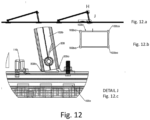
- box-shaped element 102b engages and couples with a profile 200, included in the system 100 and shown in figure 12 , and with the second base profile 102a.
- the profile 200 comprises upper flaps 200a, and lower flaps 200b able to match by snap-fit with the box-shaped element 102b, preventing overturning phenomena.
- box-shaped element 102b shown in section in figure 12b comprises four protrusions 102ba in correspondence with its outer corners, so as to reinforce the box-shaped element 102b allowing it to resist wind stresses acting on the photovoltaic panel 50, even with high inclination angles.
- the second base profile 102a also couples with a second upper element 102c.
- the second upper element 102c is provided with an external flap, suitable for the assembly of a possible windbreak casing, and with an inner C-shaped contour 102c' for mounting the frame 50a of the photovoltaic panel 50, which is inserted and brought to abutment, as shown in detail in figure 12 .
- the second base profile 102a has an upper groove 102f in which the end clamp for blocking the photovoltaic panels 50 can be fixed.
- the front and rear supports 101, 102 are fixed to the bottom profile 103 by means of two hammer head screws.
- the front and rear supports 101, 102 are fixed to the bottom profile 103 by means of a hook 110, e.g., a plastic hook, which has a front protrusion 110a, shown in figure 11 , which snaps into a hole of the first bottom element 101a.
- the hook 110 also has a hammer head contour 110b able to be fixed to the bottom profiles 103, by means of the profile 200 by inserting and rotating the hammer head contour 110b in an upper groove of the bottom profile 103.
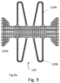
- the system 100 further comprises additional weights 106, each equipped with a fastening element, shown in figures 9 and 10 .
- the additional weights 106 are positioned on a support 120, for example a plastic support, which has side protrusions 120b, two for each side over a central symmetry line, suitable for increasing the contacting surface.
- the support 120 also has two side flaps 120c, which extend vertically and orthogonally with respect to the side protrusions 120b, necessary to laterally contain a concrete block which constitutes a preferable additional weight 106, avoiding overturning/translation due to the wind load.
- the support 120 can also be supplied without the flaps 120c themselves: in this case the friction between the support 120 and the concrete block is increased through the presence of wedge-shaped projections 120e on the flat portion of the support 120.
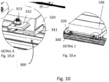
- Figure 10 shows how, according to one aspect of the invention, an additional weight 106 is supported at the bottom by an L-shaped angular bracket 320, fixed in turn by means of a further hook 300.
- the support 120 for additional weights 106 comprises in its lower portion a protrusion 120a, shown in figure 9b , and is able to be mounted by inserting such a protrusion 120a into the groove 103a of the bottom profile 103.
- the side protrusions 120b preferably equal to four protrusions, are able to increase the supporting surface of the additional weight 106, while the two side flaps 120c are able to block the additional weight.
- the support 120 also comprises a plurality of separating baffles 120d along the base of the two side flaps 120c, which favors the detachment of the two flaps 120c if the concrete block which constitutes the additional weight 106 has large dimensions and cannot be contained between the same flaps 120c.
- the support 120 further comprises over its flat portion a plurality of wedge-shaped protrusions 120e, useful to increase the friction between the support 120 itself and the lower surface of the concrete block 106.
- the rubber mat 105 interposed between the bottom profile 103 and the surface 51, whether it is an attic or a roof, is able to absorb the deformations of the structure and to generate a friction with the roof covering.
- the assembly of the rubber mat 105 to the bottom profile 103 takes place by snap fastening of a plurality of teeth 105a, present laterally on the upper surface of the rubber mat 105.
- the lower surface of the rubber mat 105 is knurled, in order to increase the friction and at the same time facilitate the flow of water.
- the longitudinal bottom profile 103 is connected to the junction elements 103d by means of four self-drilling screws to be positioned laterally.
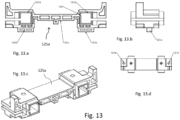
- Figure 6 shows an overall view of a template 121 for positioning the supports or bottom profiles 103.
- the template 121 is composed of at least two elements 125a, preferably three plastic elements 125a, and two parallel aluminium profiles 125b.
- the plastic elements 125a are placed and fixed transversally between the two aluminium profiles 125b.
- Figure 6b and Figure 6c show sectional views of an element 125a.
- the particular geometry of the template 121 allows both the bottom profiles 103 and the front and rear supports 101, 102 to be positioned. It is possible to adjust the distance between the three plastic elements 125a and consequently block the aluminium profiles 125b with the two pre-assembled screws.
- the front support 101 and the rear support 102 are positioned by mean of the template 121.
- the geometry of the single element 125a, 125b which constitutes the template 121 is composed of septum on the lower part necessary for coupling with the groove 103a of the bottom profile 103 both over the longitudinal direction 121a and over the transverse direction 121b.
- the element 125a is assembled with two aluminium profiles 125b which fit into the two pockets 121d. The locking of the two profiles 125b takes place by tightening the screws in correspondence with the holes 121e and by deformation of the two grooves in correspondence with the point 121f.
- the system 100 comprises at least one fixing clamp 122 suitable for the supports already described.
- the fixing clamp 122 comprises a central body 122a which differs from the snap fastening system already described.
- the assembly of the central body 122a takes place by lateral insertion into grooves 101f, 102f present, respectively, on the upper profiles of the front support 101 and of the rear support 102.
- the upper part of the fixing clamp 122 abuts with the frame 50a of the panel 50 causing the central body 122a to move upwards, with the central body 122a itself which has lower hooks which come into contact with the two upper hooks present in the groove of the upper element 101b.
- the central body 122a has two knurled side surfaces 123 which, by coupling with the knurled part 124 of the upper piece, or of the frame 50a, facilitate the locking of the entire clamp to the photovoltaic panel 50.
- the two elements 101a and 101b couple together forming a hinge and allowing the rotation of the upper element 101b on the bottom element 101a.
- the rotation allows to mount the photovoltaic panel 50 at different inclinations, up to 30° with respect to the surface 51.
- the system 100 further comprises transverse bracings, shown in figure 10 .
- the system 100 comprises locking hooks for the aforementioned transverse bracings, shown in figure 10 .
- the system 100 comprises windbreak casings, shown in figure 10 .
- Figure 10 shows the assembly of a typical configuration with three rows of PV panels 50 linked together.
- a transverse corner bracing 320 which is connected to the several bottom profiles 103 by means of a second hook 300.
- the second hook 300 (shown in detail 'K' of figure 10 ) consists of a first and a second element 311, 312, connected to each other by a hammer head screw 313.
- the first and the second element 311, 312 block the transverse corner bracing without the need to drill holes on it.
- the transverse corner bracing 320 mounted in pairs, one piece at the bottom and the other at the top, also has the function of supporting the additional weights 106 (as shown in the detail 'J' of figure 10 ) with the advantage of being able to translate the position of the fastenings thanks to the use of the hook 300, whose fixing to the bottom profile 103 is adjustable and does not require drilling.
- the system 100 comprises a plurality of windbreak casings 400. It is also possible to assemble each windbreak casing 400 in correspondence with the rear panel support 102. The fixing of the windbreak casing 400 takes place by means of self-drilling screws also exploiting the protruding wing present on the second upper element 102c.
- the geometry of the 400 windbreak casing may vary, according to the wind load present in the installation site.
- the system for a concatenated assembly of rows of photovoltaic panels allows the inclination of the PV panel 50 to be adjusted by custom-made cutting the box-shaped element 102b of the rear support 102, thus changing the height of the rear support 102 while the other profiles remain unchanged.
- the system for a concatenated assembly of rows of photovoltaic panels allows to facilitate the assembly of the PV panel, by inserting the frame on the rear support and hitting it on the front support.
- the system for a concatenated assembly of rows of photovoltaic panels allows the use of the same rotary clamp to block the panel both on the short side and on the long side.
Landscapes
- Engineering & Computer Science (AREA)
- Chemical & Material Sciences (AREA)
- Mechanical Engineering (AREA)
- Sustainable Development (AREA)
- Sustainable Energy (AREA)
- Thermal Sciences (AREA)
- Physics & Mathematics (AREA)
- Combustion & Propulsion (AREA)
- Life Sciences & Earth Sciences (AREA)
- General Engineering & Computer Science (AREA)
- Architecture (AREA)
- Civil Engineering (AREA)
- Structural Engineering (AREA)
- Photovoltaic Devices (AREA)
- Roof Covering Using Slabs Or Stiff Sheets (AREA)
Abstract
Description
- The present invention relates to a system for the concatenated assembly of rows of photovoltaic panels.
- In particular, the present invention relates to a system for a concatenated assembly of rows of photovoltaic panels useful for a concatenated installation of rows of panels arranged over a horizontal or vertical orientation, in which the panels can be fixed both on their short side and on their long side, with a variable inclination.
- Several mounting systems for photovoltaic panels are currently known.
- An example is described by the
patent application EP3161390B1 , which discloses a system for the inclined arrangement of photovoltaic modules on flat roofs comprising a front and rear support section. The profiles are mounted parallel to the flat roof using retaining elements fixed to the roof. Preferably, the upper sides of both support sections are rounded so that the photovoltaic module rests tangentially or substantially tangentially on said sections. The support sections can thus provide an optimal structural support to PV modules of various sizes at various angles. - A further mounting system is disclosed in the patent application
EP2297790B1 , describing an installation system for industrial photovoltaic plants which has the purpose of reliably holding large-scale frameless thin-film modules, considering high wind and snow loads. The installation system comprises two profiled crosspieces, parallel and spaced apart and equipped with planar support surfaces. Furthermore, it comprises a plurality of blocks fixed to the back of a photovoltaic module by means of an adhesive. - Finally, the patent application
US2014102996A1 describes an assembly system of adjustable photovoltaic panels which allows to vary roofs and covering elements of the same roofs, while maintaining a rigid and safe assembly. The specific location for supporting feet and structural members of the mounting system can be varied to allow for variations in roof characteristics and different panel configurations. The mounting mechanisms are adjustable in both north/south and east/west directions to provide maximum layout flexibility. - However, although advantageous in many aspects, the currently known assembling systems for concatenated PV modules do not allow rows of PV panels to be fixed alternately on their short side or also on their long side, and with a variable inclination, up to 30°.
- In addition, the known mounting systems do not allow the panels to be mounted in an easy and practical way.
- The purpose of the present invention is to provide a system for a concatenated assembly of rows of photovoltaic panels which allows to fix rows of such panels alternatively on their short side or on their long side, with variable inclination and in an easy and practical way, having therefore characteristics so as to overcome the limits which still affect the mounting systems of photovoltaic panels, with reference to the prior art.
- According to the present invention, a system for a concatenated assembly of rows of photovoltaic panels is provided, as defined in claim 1.
- For a better understanding of the present invention, a preferred embodiment is now described, purely by way of nonlimiting example, with reference to the attached drawings, in which:
-
figure 1 shows an overall three-dimensional view of a system for a concatenated assembly of rows of photovoltaic panels, according to the invention; -
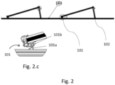
figures 2a-2b-2c show an overall side view and two detail views, respectively, of the system for a concatenated assembly of rows of photovoltaic panels, according to the invention; -
figure 3 shows a detail view of a front assembly of the system for a concatenated assembly of rows of photovoltaic panels, according to the invention; -
figures 4a-4c show schematic views of a rear assembly of the system for a concatenated assembly of rows of photovoltaic panels, according to the invention; -
figures 5a-5f show schematic overall and detail views of the system for a concatenated assembly of rows of photovoltaic panels, according to the invention; -
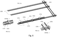
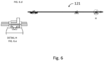
figures 6a-6e show schematic overall and detail views of the system for a concatenated assembly of rows of photovoltaic panels, according to the invention; -
figures 7a-7b show schematic detail views of a junction of the system for a concatenated assembly of rows of photovoltaic panels, according to the invention; -
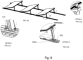
figures 8a-8e show schematic detail views of elements of the system for a concatenated assembly of rows of photovoltaic panels, according to the invention; -
figures 9a-9c show schematic detail views of an additional weight of the system for a concatenated assembly of rows of photovoltaic panels, according to the invention; -
figures 10a-10c show further schematic overall and detail views of the system for a concatenated assembly of rows of photovoltaic panels, according to the invention; -
figures 11a-11f show schematic views of a hook of the system for a concatenated assembly of rows of photovoltaic panels, according to the invention; -
figures 12a-12d show detail views of the system for a concatenated assembly of rows of photovoltaic panels, according to the invention; -
figures 13a-13d show views of a template of the system for a concatenated assembly of rows of photovoltaic panels, according to the invention; -
figures 14a-14b show, respectively, a sectional view of a base profile and of a junction of the base profile of the system for a concatenated assembly of rows of photovoltaic panels, according to the invention. - With reference to these figures, and in particular to
figure 1 , a system for a concatenated assembly of rows of photovoltaic panels is shown, according to the invention. - In more detail, a system 100 for a concatenated assembly of rows of photovoltaic panels, configured for mounting at least one
photovoltaic panel 50 over asurface 51, comprises: - at least one
bottom profile 103 mounted longitudinally over thesurface 51, for example a roof, and comprising, in correspondence with an upper portion, a longitudinal andcentral groove 103a; - at least one
front support 101 anchored to the at least onebottom profile 103 and to a front portion of the at least onephotovoltaic panel 50; - at least one
rear support 102, anchored to thebottom profile 103 and to a rear portion of thephotovoltaic panel 50, having a predefined height depending on the inclination required for thephotovoltaic panel 50. - Therefore, according to the invention, two
front supports 101 and tworear supports 102 are fixed to eachphotovoltaic panel 50. - Preferably, the system 100 comprises a
rubber mat 105, made of EPDM, placed between thesurface 51 and thebottom profile 103. - According to one aspect of the invention, the system 100 further comprises:
- at least one
junction element 103d to thebottom profile 103, shown infigure 7 and infigure 14b ; - at least one locking clamp of the
photovoltaic panels 50. - According to one aspect of the invention, the
bottom profile 103 comprises in correspondence with an upper portion a longitudinal andcentral groove 103a, shown infigure 7 and infigure 14 . - According to one aspect of the invention, the
front support 101 consists of: - a
first bottom element 101a able to be fixed to the longitudinal andcentral groove 103a of thebottom profile 103 through hammer head screws, and a firstupper element 101b to which thefirst bottom element 101a matches forming a hinge, as shown infigure 2c , so that the firstupper element 101b is able to rotate within a predetermined angle with respect to thefirst bottom element 101a. - According to one aspect of the invention, a
frame 50a of thephotovoltaic panel 50 is placed on the firstupper element 101b, while an end clamp is mounted and fixed in thegroove 103a. - According to one aspect of the invention, the
rear support 102 comprises asecond base profile 102a, and a box-shapedelement 102b which engages and couples, by means of a through bolt, both with thebottom profile 103 and with thesecond base profile 102a. - In particular, the box-shaped
element 102b engages and couples with aprofile 200, included in the system 100 and shown infigure 12 , and with thesecond base profile 102a. - The
profile 200 comprises upper flaps 200a, and lower flaps 200b able to match by snap-fit with the box-shapedelement 102b, preventing overturning phenomena. - Furthermore, the box-shaped
element 102b shown in section infigure 12b comprises four protrusions 102ba in correspondence with its outer corners, so as to reinforce the box-shapedelement 102b allowing it to resist wind stresses acting on thephotovoltaic panel 50, even with high inclination angles. - The
second base profile 102a also couples with a secondupper element 102c. The secondupper element 102c is provided with an external flap, suitable for the assembly of a possible windbreak casing, and with an inner C-shapedcontour 102c' for mounting theframe 50a of thephotovoltaic panel 50, which is inserted and brought to abutment, as shown in detail infigure 12 . - The
second base profile 102a has anupper groove 102f in which the end clamp for blocking thephotovoltaic panels 50 can be fixed. - According to one aspect of the invention, as shown in
figure 8 , the front andrear supports bottom profile 103 by means of two hammer head screws. - Alternatively, according to another aspect of the invention, the front and
rear supports bottom profile 103 by means of ahook 110, e.g., a plastic hook, which has afront protrusion 110a, shown infigure 11 , which snaps into a hole of thefirst bottom element 101a. Thehook 110 also has ahammer head contour 110b able to be fixed to the bottom profiles 103, by means of theprofile 200 by inserting and rotating thehammer head contour 110b in an upper groove of thebottom profile 103. - According to one aspect of the invention, the system 100 further comprises
additional weights 106, each equipped with a fastening element, shown infigures 9 and10 . - According to one aspect of the invention, the
additional weights 106 are positioned on asupport 120, for example a plastic support, which hasside protrusions 120b, two for each side over a central symmetry line, suitable for increasing the contacting surface. Thesupport 120 also has twoside flaps 120c, which extend vertically and orthogonally with respect to theside protrusions 120b, necessary to laterally contain a concrete block which constitutes a preferableadditional weight 106, avoiding overturning/translation due to the wind load. If theadditional weight 106 has huge dimensions, such as not to be contained between the twoside flaps 120c, thesupport 120 can also be supplied without theflaps 120c themselves: in this case the friction between thesupport 120 and the concrete block is increased through the presence of wedge-shapedprojections 120e on the flat portion of thesupport 120. -
Figure 10 shows how, according to one aspect of the invention, anadditional weight 106 is supported at the bottom by an L-shapedangular bracket 320, fixed in turn by means of afurther hook 300. - According to one aspect of the invention, the
support 120 foradditional weights 106, shown infigure 9a , comprises in its lower portion aprotrusion 120a, shown infigure 9b , and is able to be mounted by inserting such aprotrusion 120a into thegroove 103a of thebottom profile 103. Theside protrusions 120b, preferably equal to four protrusions, are able to increase the supporting surface of theadditional weight 106, while the twoside flaps 120c are able to block the additional weight. Thesupport 120 also comprises a plurality of separatingbaffles 120d along the base of the twoside flaps 120c, which favors the detachment of the twoflaps 120c if the concrete block which constitutes theadditional weight 106 has large dimensions and cannot be contained between thesame flaps 120c. - According to one aspect of the invention, the
support 120 further comprises over its flat portion a plurality of wedge-shapedprotrusions 120e, useful to increase the friction between thesupport 120 itself and the lower surface of theconcrete block 106. - According to one aspect of the invention, as shown in
figure 8f , therubber mat 105 interposed between thebottom profile 103 and thesurface 51, whether it is an attic or a roof, is able to absorb the deformations of the structure and to generate a friction with the roof covering. - The assembly of the
rubber mat 105 to thebottom profile 103, preferably made of aluminium, takes place by snap fastening of a plurality ofteeth 105a, present laterally on the upper surface of therubber mat 105. The lower surface of therubber mat 105 is knurled, in order to increase the friction and at the same time facilitate the flow of water. - According to one aspect of the invention, as shown in
figure 7 , the longitudinalbottom profile 103 is connected to thejunction elements 103d by means of four self-drilling screws to be positioned laterally. -
Figure 6 shows an overall view of atemplate 121 for positioning the supports orbottom profiles 103. Thetemplate 121 is composed of at least twoelements 125a, preferably threeplastic elements 125a, and twoparallel aluminium profiles 125b. Theplastic elements 125a are placed and fixed transversally between the twoaluminium profiles 125b. -
Figure 6b and Figure 6c show sectional views of anelement 125a. - Advantageously, the particular geometry of the
template 121 allows both the bottom profiles 103 and the front andrear supports plastic elements 125a and consequently block thealuminium profiles 125b with the two pre-assembled screws. - The
front support 101 and therear support 102 are positioned by mean of thetemplate 121. - According to one aspect of the invention, the geometry of the
single element template 121 is composed of septum on the lower part necessary for coupling with thegroove 103a of thebottom profile 103 both over the longitudinal direction 121a and over thetransverse direction 121b. Theelement 125a is assembled with twoaluminium profiles 125b which fit into the twopockets 121d. The locking of the twoprofiles 125b takes place by tightening the screws in correspondence with theholes 121e and by deformation of the two grooves in correspondence with the point 121f. - According to one aspect of the invention, as shown in
fig. 5 , the system 100 comprises at least one fixingclamp 122 suitable for the supports already described. The fixingclamp 122 comprises acentral body 122a which differs from the snap fastening system already described. - The assembly of the
central body 122a takes place by lateral insertion intogrooves front support 101 and of therear support 102. During the tightening of the screw, the upper part of the fixingclamp 122 abuts with theframe 50a of thepanel 50 causing thecentral body 122a to move upwards, with thecentral body 122a itself which has lower hooks which come into contact with the two upper hooks present in the groove of theupper element 101b. - According to one aspect of the invention, the
central body 122a has two knurled side surfaces 123 which, by coupling with theknurled part 124 of the upper piece, or of theframe 50a, facilitate the locking of the entire clamp to thephotovoltaic panel 50. - According to another aspect of the invention, with reference to the detail view `I' of
figure 5 , the twoelements upper element 101b on thebottom element 101a. The rotation allows to mount thephotovoltaic panel 50 at different inclinations, up to 30° with respect to thesurface 51. - According to another aspect of the invention, the system 100 further comprises transverse bracings, shown in
figure 10 . - According to one aspect of the invention, the system 100 comprises locking hooks for the aforementioned transverse bracings, shown in
figure 10 . - According to another aspect of the invention, the system 100 comprises windbreak casings, shown in
figure 10 . -
Figure 10 shows the assembly of a typical configuration with three rows ofPV panels 50 linked together. In order to stiffen theframe 50a it is used a transverse corner bracing 320, which is connected to the severalbottom profiles 103 by means of asecond hook 300. - According to one aspect of the invention, the second hook 300 (shown in detail 'K' of
figure 10 ) consists of a first and asecond element hammer head screw 313. The first and thesecond element - The transverse corner bracing 320 mounted in pairs, one piece at the bottom and the other at the top, also has the function of supporting the additional weights 106 (as shown in the detail 'J' of
figure 10 ) with the advantage of being able to translate the position of the fastenings thanks to the use of thehook 300, whose fixing to thebottom profile 103 is adjustable and does not require drilling. - According to one aspect of the invention, the system 100 comprises a plurality of
windbreak casings 400. It is also possible to assemble each windbreak casing 400 in correspondence with therear panel support 102. The fixing of the windbreak casing 400 takes place by means of self-drilling screws also exploiting the protruding wing present on the secondupper element 102c. - The geometry of the 400 windbreak casing may vary, according to the wind load present in the installation site.
- Advantageously according to the invention, the system for a concatenated assembly of rows of photovoltaic panels allows the inclination of the
PV panel 50 to be adjusted by custom-made cutting the box-shapedelement 102b of therear support 102, thus changing the height of therear support 102 while the other profiles remain unchanged. - Advantageously according to the invention, the system for a concatenated assembly of rows of photovoltaic panels allows to facilitate the assembly of the PV panel, by inserting the frame on the rear support and hitting it on the front support.
- Advantageously according to the invention, the system for a concatenated assembly of rows of photovoltaic panels allows the use of the same rotary clamp to block the panel both on the short side and on the long side.
- It is finally clear that the system for a concatenated assembly of rows of photovoltaic panels, described and illustrated herein, may be subject to modifications and variations without departing from the protective scope of the present invention, as defined in the appended claims.
Claims (10)
- System (100) for a concatenated assembly of rows of photovoltaic panels, configured for mounting at least one photovoltaic panel (50) over a surface (51), comprising:- at least one bottom profile (103) mounted longitudinally over the surface (51) and comprising, in correspondence with an upper portion, a longitudinal and central groove (103a);- at least one front support (101) anchored to the at least one bottom profile (103) and to a front portion of the at least one photovoltaic panel (50), consisting of: a first bottom element (101a) able to be fixed to the longitudinal and central groove (103a) of the at least one bottom profile (103), and a first upper element (101b) to which the first bottom element (101a) matches forming a hinge, so that the first upper element (101b) is able to rotate within a predetermined angle with respect to the first bottom element (101a);- at least one rear support (102) anchored to the at least one bottom profile (103) and to a rear portion of the at least one photovoltaic panel (50), comprising a second base profile (102a) comprising an upper groove, a box-shaped element (102b) engaging and matching with both the at least one bottom profile (103) and the second base profile (102a), and a second upper element (102c) matched with the second base profile (102a);
characterized in that said second upper element (102c) comprises an external flap and an inner C-shaped contour (102c') for mounting a frame (50a) of the at least one photovoltaic panel (50) which is inserted and brought to abutment. - System (100) according to claim 1, characterized in comprising a profile (200) for fixing the box-shaped element (102b) to the at least one bottom profile (103), said profile (200) comprising upper flaps (200a) and lower flaps (200b) able to match by snap-fit with the box-shaped element (102b).
- System (100) according to claim 1, characterized in comprising:- at least one joining element (108) to the at least one bottom profile (103);- at least one locking clamp of the at least one photovoltaic panel (50).
- System (100) according to claim 1, characterized in comprising a hook (110) for fixing the at least one front support (101) and the at least one rear support (102) to the at least one bottom profile (103), said hook (110) comprising a front protrusion (110a) able to be snapped into a hole of the first bottom element (101a), and a hammer head contour (110b) configured to be fixed to the at least one bottom profile (103) by inserting and rotating the hammer head contour (110b) in an upper groove of the at least one bottom profile (103)
- System (100) according to claim 1, characterized in comprising a support (120) for additional weights (106) comprising:- in a lower portion a protrusion (120a), able to be inserted in the groove of the at least one bottom profile (103);- four side protrusions (120b), able to increase the supporting surface of the additional weight (106);- two side flaps (120c) able to block the additional weights (106);- a plurality of separator baffles (120d) along the base of the two side flaps (120c), configured for the detachment of said two side flaps (120c) in case the additional weight (106) has increased dimensions and is not able to be contained between the two side flaps (120c)- comprises also in correspondence with a flat portion a plurality of wedge-shaped protrusions (120e) able to increase the friction between the support (120) and the lower surface of the additional weight (106).
- System (100) according to claim 1, characterized in comprising a rubber mat (105) interposed between said at least one bottom profile (103) and the surface (51), able to absorb the deformations of the structure and to generate a friction with a covering roof, said rubber mat (105) comprising on an upper surface a plurality of teeth (105a) able for snap fastening the rubber mat (105) to the at least one bottom profile (103).
- System (100) according to claim 1, characterized in comprising at least one fixing clamp (122) comprising a central body (122a) able to be inserted laterally into grooves (101f, 102f) comprised on upper profiles respectively of the at least one front support (101) and of the at least one rear support (102), said central body (122a) having lower hooks which abut with two upper hooks included in the groove of the upper profile (101b) and two knurled side surfaces able to be coupled to a knurled portion of the upper piece, configured for the locking of the fixing clamp (122) to the at least one photovoltaic panel (50).
- System (100) according to claim 1, characterized in comprising a plurality of transverse bracings and a plurality of hooks locking each transverse bracing to the at least one bottom profile (103), each hook comprised in the plurality of hooks consisting of two elements (311, 312), connected by means of a hammer head screw (313), able to lock the transverse bracing without the need to drill holes on said transverse bracing.
- System (100) according to claim 1, characterized in comprising a plurality of windbreak casings (400), fixed in correspondence with the at least one rear support (102) in proximity of the box-shaped element (102b).
- System (100) according to claim 1, characterized in comprising a template (121), consisting of three plastic elements (125a) and two parallel aluminium profiles (125b), in which the elements (125a) are fixed transversally to the two profiles (125b), said template (121) being configured for the positioning of the bottom profiles (103) and of the front (101) and rear (102) supports, each of said plastic elements (125a) comprising in correspondence with a lower part a septum over a longitudinal direction (121a) and a septum over a transverse direction (121b), two pockets (121d), and a plurality of holes (121e) for housing tightening screws able to fix the parallel aluminium profiles (125b).
Priority Applications (1)
| Application Number | Priority Date | Filing Date | Title |
|---|---|---|---|
| HRP20251411TT HRP20251411T1 (en) | 2022-03-18 | 2023-03-17 | SYSTEM FOR CONNECTING ROWS OF PHOTOVOLTAIC PANEL |
Applications Claiming Priority (1)
| Application Number | Priority Date | Filing Date | Title |
|---|---|---|---|
| IT102022000005417A IT202200005417A1 (en) | 2022-03-18 | 2022-03-18 | Chained assembly system of rows of photovoltaic panels |
Publications (3)
| Publication Number | Publication Date |
|---|---|
| EP4246053A1 true EP4246053A1 (en) | 2023-09-20 |
| EP4246053C0 EP4246053C0 (en) | 2025-08-13 |
| EP4246053B1 EP4246053B1 (en) | 2025-08-13 |
Family
ID=81928138
Family Applications (1)
| Application Number | Title | Priority Date | Filing Date |
|---|---|---|---|
| EP23162611.0A Active EP4246053B1 (en) | 2022-03-18 | 2023-03-17 | System for the concatenated assembly of rows of photovoltaic panels |
Country Status (4)
| Country | Link |
|---|---|
| EP (1) | EP4246053B1 (en) |
| ES (1) | ES3052474T3 (en) |
| HR (1) | HRP20251411T1 (en) |
| IT (1) | IT202200005417A1 (en) |
Cited By (1)
| Publication number | Priority date | Publication date | Assignee | Title |
|---|---|---|---|---|
| IT202400000645A1 (en) * | 2024-01-16 | 2025-07-16 | Contact Italia S R L | TOOL-FREE FIXING SYSTEM FOR PHOTOVOLTAIC SYSTEMS |
Citations (8)
| Publication number | Priority date | Publication date | Assignee | Title |
|---|---|---|---|---|
| DE202009007490U1 (en) * | 2009-05-26 | 2009-08-20 | Green Factory Gmbh | Device for fixing a module for the use of solar energy |
| US20110174353A1 (en) * | 2008-06-11 | 2011-07-21 | Schletter Gmbh | Installation system for pv modules |
| US20140102996A1 (en) | 2011-10-11 | 2014-04-17 | Todd Pelman | Structure following roof mounted photovoltaic system |
| US20140224165A1 (en) * | 2011-04-15 | 2014-08-14 | Ciel Et Terre International | Panel supporting device |
| CA2829919A1 (en) * | 2013-10-11 | 2015-04-11 | Polar Racking Inc. | Support racking for solar panel |
| US20150129014A1 (en) * | 2012-05-03 | 2015-05-14 | Yunhua Shu | Folded Photovoltaic Assembly Mounting Structure And Mounting Method Therefor |
| EP3161390B1 (en) | 2009-02-17 | 2019-08-07 | Schletter International B.V. | Inclined arrangement of pv modules on flat roofs |
| US20200266755A1 (en) * | 2011-03-01 | 2020-08-20 | Ecolibrium Solar, Inc. | Support Assembly For Photovoltaic Modules And Mounting System Using The Same |
Family Cites Families (5)
| Publication number | Priority date | Publication date | Assignee | Title |
|---|---|---|---|---|
| DE20204146U1 (en) * | 2002-03-15 | 2002-05-16 | Schüco International KG, 33609 Bielefeld | Device for mounting a collector and fastening element |
| ITVI20080294A1 (en) * | 2008-12-10 | 2010-06-11 | Alutecnica Srl | SHOE FOR THE CONNECTION OF STRUCTURAL ELEMENTS, ARTICULATED JOINT INCLUDING SUCH SHOE AND STRUCTURE INCLUDING SUCH ARTICULATED JOINT |
| DE102009023021A1 (en) * | 2009-05-28 | 2010-12-02 | Adensis Gmbh | Clamp connection for module rails in photovoltaic systems |
| US10033328B2 (en) * | 2011-03-01 | 2018-07-24 | Ecolibrium Solar, Inc. | Support member for mounting photovoltaic modules and mounting system including the same |
| CN211876393U (en) * | 2020-03-06 | 2020-11-06 | 厦门华谱科技有限公司 | Solar panel fixing device capable of changing inclination angle |
-
2022
- 2022-03-18 IT IT102022000005417A patent/IT202200005417A1/en unknown
-
2023
- 2023-03-17 HR HRP20251411TT patent/HRP20251411T1/en unknown
- 2023-03-17 EP EP23162611.0A patent/EP4246053B1/en active Active
- 2023-03-17 ES ES23162611T patent/ES3052474T3/en active Active
Patent Citations (9)
| Publication number | Priority date | Publication date | Assignee | Title |
|---|---|---|---|---|
| US20110174353A1 (en) * | 2008-06-11 | 2011-07-21 | Schletter Gmbh | Installation system for pv modules |
| EP2297790B1 (en) | 2008-06-11 | 2016-08-10 | Schletter GmbH | Mounting system for a pv-module |
| EP3161390B1 (en) | 2009-02-17 | 2019-08-07 | Schletter International B.V. | Inclined arrangement of pv modules on flat roofs |
| DE202009007490U1 (en) * | 2009-05-26 | 2009-08-20 | Green Factory Gmbh | Device for fixing a module for the use of solar energy |
| US20200266755A1 (en) * | 2011-03-01 | 2020-08-20 | Ecolibrium Solar, Inc. | Support Assembly For Photovoltaic Modules And Mounting System Using The Same |
| US20140224165A1 (en) * | 2011-04-15 | 2014-08-14 | Ciel Et Terre International | Panel supporting device |
| US20140102996A1 (en) | 2011-10-11 | 2014-04-17 | Todd Pelman | Structure following roof mounted photovoltaic system |
| US20150129014A1 (en) * | 2012-05-03 | 2015-05-14 | Yunhua Shu | Folded Photovoltaic Assembly Mounting Structure And Mounting Method Therefor |
| CA2829919A1 (en) * | 2013-10-11 | 2015-04-11 | Polar Racking Inc. | Support racking for solar panel |
Cited By (2)
| Publication number | Priority date | Publication date | Assignee | Title |
|---|---|---|---|---|
| IT202400000645A1 (en) * | 2024-01-16 | 2025-07-16 | Contact Italia S R L | TOOL-FREE FIXING SYSTEM FOR PHOTOVOLTAIC SYSTEMS |
| WO2025153859A1 (en) * | 2024-01-16 | 2025-07-24 | Contact Italia S.R.L. | System for fastening photovoltaic systems without using tools |
Also Published As
| Publication number | Publication date |
|---|---|
| EP4246053C0 (en) | 2025-08-13 |
| ES3052474T3 (en) | 2026-01-07 |
| IT202200005417A1 (en) | 2023-09-18 |
| HRP20251411T1 (en) | 2026-01-30 |
| EP4246053B1 (en) | 2025-08-13 |
Similar Documents
| Publication | Publication Date | Title |
|---|---|---|
| EP2413063B1 (en) | Slider clip and photovolatic structure mounting system | |
| US9780719B2 (en) | East-west photovoltaic array with spaced apart photovoltaic modules for improved aerodynamic efficiency | |
| US7260918B2 (en) | Apparatus and method for positioning a module on an object | |
| EP1449262B1 (en) | Photovoltaic array | |
| US8667748B2 (en) | Photovoltaic module ground mount | |
| US8464496B2 (en) | Support system for solar panels | |
| JP5365937B2 (en) | Solar panel mounting device | |
| KR101903727B1 (en) | A roof panel system | |
| WO2013065130A1 (en) | Solar cell module fixing structure | |
| JPH1113238A (en) | Stand for solar cell module | |
| EP4246053B1 (en) | System for the concatenated assembly of rows of photovoltaic panels | |
| KR102257881B1 (en) | Solar Module of Magnetic Attachment Type | |
| KR20200055875A (en) | Height adjustment device for solar panel assambly | |
| KR102746941B1 (en) | Mounting apparatus on roof panel of installation structure for solar panel | |
| JP6692036B2 (en) | Fixing bracket mounting structure | |
| US20110266234A1 (en) | Mounting system for solar modules and method for installing a solar system | |
| JP2020096418A (en) | Gradient adjustment mechanism for longitudinal beam of panel frame | |
| US20120174913A1 (en) | Module Arrangement Consisting of Solar Modules | |
| KR101826395B1 (en) | Sound Proof Tunnel Using Truss Type Roof Frame | |
| KR102922715B1 (en) | building integrated photovoltaic system | |
| CN108471281B (en) | Solar panel fixing frame | |
| JP6688963B2 (en) | Solar power generator | |
| KR102435714B1 (en) | Roof system including roof panel support assembly and building construction method using same | |
| JP6968559B2 (en) | Stand for solar cell module and photovoltaic power generation device | |
| CN224264895U (en) | An adjustable photovoltaic bracket and photovoltaic module |
Legal Events
| Date | Code | Title | Description |
|---|---|---|---|
| REG | Reference to a national code |
Ref country code: HR Ref legal event code: TUEP Ref document number: P20251411T Country of ref document: HR |
|
| PUAI | Public reference made under article 153(3) epc to a published international application that has entered the european phase |
Free format text: ORIGINAL CODE: 0009012 |
|
| STAA | Information on the status of an ep patent application or granted ep patent |
Free format text: STATUS: THE APPLICATION HAS BEEN PUBLISHED |
|
| AK | Designated contracting states |
Kind code of ref document: A1 Designated state(s): AL AT BE BG CH CY CZ DE DK EE ES FI FR GB GR HR HU IE IS IT LI LT LU LV MC ME MK MT NL NO PL PT RO RS SE SI SK SM TR |
|
| STAA | Information on the status of an ep patent application or granted ep patent |
Free format text: STATUS: REQUEST FOR EXAMINATION WAS MADE |
|
| 17P | Request for examination filed |
Effective date: 20240312 |
|
| RBV | Designated contracting states (corrected) |
Designated state(s): AL AT BE BG CH CY CZ DE DK EE ES FI FR GB GR HR HU IE IS IT LI LT LU LV MC ME MK MT NL NO PL PT RO RS SE SI SK SM TR |
|
| GRAP | Despatch of communication of intention to grant a patent |
Free format text: ORIGINAL CODE: EPIDOSNIGR1 |
|
| STAA | Information on the status of an ep patent application or granted ep patent |
Free format text: STATUS: GRANT OF PATENT IS INTENDED |
|
| RIC1 | Information provided on ipc code assigned before grant |
Ipc: F24S 25/00 20180101ALN20250305BHEP Ipc: F24S 25/10 20180101ALN20250305BHEP Ipc: H02S 30/00 20140101ALI20250305BHEP Ipc: H02S 20/24 20140101ALI20250305BHEP Ipc: F24S 25/33 20180101ALI20250305BHEP Ipc: F24S 25/60 20180101ALI20250305BHEP Ipc: H02S 20/23 20140101ALI20250305BHEP Ipc: F24S 25/70 20180101ALI20250305BHEP Ipc: F24S 25/65 20180101ALI20250305BHEP Ipc: F24S 25/636 20180101AFI20250305BHEP |
|
| INTG | Intention to grant announced |
Effective date: 20250317 |
|
| GRAS | Grant fee paid |
Free format text: ORIGINAL CODE: EPIDOSNIGR3 |
|
| GRAA | (expected) grant |
Free format text: ORIGINAL CODE: 0009210 |
|
| STAA | Information on the status of an ep patent application or granted ep patent |
Free format text: STATUS: THE PATENT HAS BEEN GRANTED |
|
| AK | Designated contracting states |
Kind code of ref document: B1 Designated state(s): AL AT BE BG CH CY CZ DE DK EE ES FI FR GB GR HR HU IE IS IT LI LT LU LV MC ME MK MT NL NO PL PT RO RS SE SI SK SM TR |
|
| REG | Reference to a national code |
Ref country code: GB Ref legal event code: FG4D |
|
| REG | Reference to a national code |
Ref country code: CH Ref legal event code: EP |
|
| REG | Reference to a national code |
Ref country code: DE Ref legal event code: R096 Ref document number: 602023005583 Country of ref document: DE |
|
| REG | Reference to a national code |
Ref country code: IE Ref legal event code: FG4D |
|
| U01 | Request for unitary effect filed |
Effective date: 20250911 |
|
| U07 | Unitary effect registered |
Designated state(s): AT BE BG DE DK EE FI FR IT LT LU LV MT NL PT RO SE SI Effective date: 20250918 |
|
| REG | Reference to a national code |
Ref country code: CH Ref legal event code: R17 Free format text: ST27 STATUS EVENT CODE: U-0-0-R10-R17 (AS PROVIDED BY THE NATIONAL OFFICE) Effective date: 20251105 |
|
| REG | Reference to a national code |
Ref country code: ES Ref legal event code: FG2A Ref document number: 3052474 Country of ref document: ES Kind code of ref document: T3 Effective date: 20260107 |
|
| PG25 | Lapsed in a contracting state [announced via postgrant information from national office to epo] |
Ref country code: IS Free format text: LAPSE BECAUSE OF FAILURE TO SUBMIT A TRANSLATION OF THE DESCRIPTION OR TO PAY THE FEE WITHIN THE PRESCRIBED TIME-LIMIT Effective date: 20251213 |
|
| PG25 | Lapsed in a contracting state [announced via postgrant information from national office to epo] |
Ref country code: NO Free format text: LAPSE BECAUSE OF FAILURE TO SUBMIT A TRANSLATION OF THE DESCRIPTION OR TO PAY THE FEE WITHIN THE PRESCRIBED TIME-LIMIT Effective date: 20251113 |
|
| REG | Reference to a national code |
Ref country code: SK Ref legal event code: T3 Ref document number: E 47471 Country of ref document: SK |
|
| PG25 | Lapsed in a contracting state [announced via postgrant information from national office to epo] |
Ref country code: GR Free format text: LAPSE BECAUSE OF FAILURE TO SUBMIT A TRANSLATION OF THE DESCRIPTION OR TO PAY THE FEE WITHIN THE PRESCRIBED TIME-LIMIT Effective date: 20251114 |
|
| PG25 | Lapsed in a contracting state [announced via postgrant information from national office to epo] |
Ref country code: PL Free format text: LAPSE BECAUSE OF FAILURE TO SUBMIT A TRANSLATION OF THE DESCRIPTION OR TO PAY THE FEE WITHIN THE PRESCRIBED TIME-LIMIT Effective date: 20250813 |
|
| PG25 | Lapsed in a contracting state [announced via postgrant information from national office to epo] |
Ref country code: RS Free format text: LAPSE BECAUSE OF FAILURE TO SUBMIT A TRANSLATION OF THE DESCRIPTION OR TO PAY THE FEE WITHIN THE PRESCRIBED TIME-LIMIT Effective date: 20251113 |
|
| REG | Reference to a national code |
Ref country code: HR Ref legal event code: T1PR Ref document number: P20251411 Country of ref document: HR |
|
| REG | Reference to a national code |
Ref country code: CH Ref legal event code: U11 Free format text: ST27 STATUS EVENT CODE: U-0-0-U10-U11 (AS PROVIDED BY THE NATIONAL OFFICE) Effective date: 20260401 |
|
| PG25 | Lapsed in a contracting state [announced via postgrant information from national office to epo] |
Ref country code: SM Free format text: LAPSE BECAUSE OF FAILURE TO SUBMIT A TRANSLATION OF THE DESCRIPTION OR TO PAY THE FEE WITHIN THE PRESCRIBED TIME-LIMIT Effective date: 20250813 |
|
| REG | Reference to a national code |
Ref country code: HR Ref legal event code: ODRP Ref document number: P20251411 Country of ref document: HR Payment date: 20260312 Year of fee payment: 4 |
|
| PGFP | Annual fee paid to national office [announced via postgrant information from national office to epo] |
Ref country code: HR Payment date: 20260312 Year of fee payment: 4 |
|
| U20 | Renewal fee for the european patent with unitary effect paid |
Year of fee payment: 4 Effective date: 20260310 |
|
| PGFP | Annual fee paid to national office [announced via postgrant information from national office to epo] |
Ref country code: HU Payment date: 20260323 Year of fee payment: 4 |
|
| PGFP | Annual fee paid to national office [announced via postgrant information from national office to epo] |
Ref country code: CZ Payment date: 20260312 Year of fee payment: 4 |
|
| PGFP | Annual fee paid to national office [announced via postgrant information from national office to epo] |
Ref country code: SK Payment date: 20260317 Year of fee payment: 4 |