EP4246050A1 - Air conditioning device, and learning device of air conditioning device - Google Patents
Air conditioning device, and learning device of air conditioning device Download PDFInfo
- Publication number
- EP4246050A1 EP4246050A1 EP20961517.8A EP20961517A EP4246050A1 EP 4246050 A1 EP4246050 A1 EP 4246050A1 EP 20961517 A EP20961517 A EP 20961517A EP 4246050 A1 EP4246050 A1 EP 4246050A1
- Authority
- EP
- European Patent Office
- Prior art keywords
- thermistors
- temperatures detected
- temperature
- time
- discharge
- Prior art date
- Legal status (The legal status is an assumption and is not a legal conclusion. Google has not performed a legal analysis and makes no representation as to the accuracy of the status listed.)
- Granted
Links
Images







Classifications
-
- F—MECHANICAL ENGINEERING; LIGHTING; HEATING; WEAPONS; BLASTING
- F24—HEATING; RANGES; VENTILATING
- F24F—AIR-CONDITIONING; AIR-HUMIDIFICATION; VENTILATION; USE OF AIR CURRENTS FOR SCREENING
- F24F11/00—Control or safety arrangements
- F24F11/62—Control or safety arrangements characterised by the type of control or by internal processing, e.g. using fuzzy logic, adaptive control or estimation of values
- F24F11/63—Electronic processing
- F24F11/64—Electronic processing using pre-stored data
-
- F—MECHANICAL ENGINEERING; LIGHTING; HEATING; WEAPONS; BLASTING
- F24—HEATING; RANGES; VENTILATING
- F24F—AIR-CONDITIONING; AIR-HUMIDIFICATION; VENTILATION; USE OF AIR CURRENTS FOR SCREENING
- F24F11/00—Control or safety arrangements
- F24F11/62—Control or safety arrangements characterised by the type of control or by internal processing, e.g. using fuzzy logic, adaptive control or estimation of values
-
- F—MECHANICAL ENGINEERING; LIGHTING; HEATING; WEAPONS; BLASTING
- F24—HEATING; RANGES; VENTILATING
- F24F—AIR-CONDITIONING; AIR-HUMIDIFICATION; VENTILATION; USE OF AIR CURRENTS FOR SCREENING
- F24F11/00—Control or safety arrangements
- F24F11/62—Control or safety arrangements characterised by the type of control or by internal processing, e.g. using fuzzy logic, adaptive control or estimation of values
- F24F11/63—Electronic processing
-
- F—MECHANICAL ENGINEERING; LIGHTING; HEATING; WEAPONS; BLASTING
- F24—HEATING; RANGES; VENTILATING
- F24F—AIR-CONDITIONING; AIR-HUMIDIFICATION; VENTILATION; USE OF AIR CURRENTS FOR SCREENING
- F24F2110/00—Control inputs relating to air properties
- F24F2110/10—Temperature
-
- F—MECHANICAL ENGINEERING; LIGHTING; HEATING; WEAPONS; BLASTING
- F24—HEATING; RANGES; VENTILATING
- F24F—AIR-CONDITIONING; AIR-HUMIDIFICATION; VENTILATION; USE OF AIR CURRENTS FOR SCREENING
- F24F2130/00—Control inputs relating to environmental factors not covered by group F24F2110/00
- F24F2130/10—Weather information or forecasts
Definitions
- the present disclosure relates to an air conditioning device and a learning device of an air conditioning device.
- An air conditioning device which includes multiple indoor units and allows each indoor unit to perform a thermo-OFF operation.
- the air conditioning device disclosed in PTL 1 has a refrigerant circuit in which multiple indoor units individually having an indoor heat exchanger and an indoor expansion valve and an outdoor unit having an outdoor expansion valve are connected by a liquid refrigerant communication tube and a gas refrigerant communication tube.
- the indoor units perform the thermo-OFF operations independent of each other.
- the outdoor apparatus needs to reduce the circulation volume of the refrigerant for that indoor unit in order to keep the high pressure and the low pressure of the compressor within an operating range. As a result, the circulation volume of the refrigerant of the entire air conditioning device rapidly decreases, ending up with perturbation of the temperature of the drawn-in air.
- an object of the present disclosure is to provide an air conditioning device which includes multiple indoor units capable of a thermo-OFF operation and allows stabilized temperature of the drawn-in air, and a learning device of an air conditioning device.
- the present disclosure is an air conditioning device which includes an indoor apparatus and an outdoor apparatus.
- the outdoor apparatus includes a compressor and an outdoor heat exchanger.
- the indoor apparatus includes a plurality of indoor units and a fan.
- Each indoor unit includes a controller, an indoor heat exchanger, an electronic expansion valve, an intake thermistor for detecting a drawn-in air temperature, and a discharge thermistor for detecting a discharged air temperature, and performs a thermo-OFF operation when the temperature detected by the discharge thermistor reaches a reference value.
- the air conditioning device further includes a first inference device to infer whether any of the plurality of indoor units performs a thermo-OFF operation during a future period of time, from a factor including a set temperature, temperatures detected by the plurality of intake thermistors, and temperatures detected by the plurality of discharge thermistors during a past period of time.
- the present disclosure is a learning device of an air conditioning device which includes an indoor apparatus and an outdoor apparatus.
- the outdoor apparatus includes a compressor and an outdoor heat exchanger.
- the indoor apparatus includes a plurality of indoor units and a fan.
- Each indoor unit includes a controller, an indoor heat exchanger, an electronic expansion valve, an intake thermistor that detects a drawn-in air temperature, and a discharge thermistor that detects a discharged air temperature, and the indoor unit performs a thermo-OFF operation when the temperature detected by the discharge thermistor reaches a reference value.
- the learning device of the air conditioning device includes: a first data acquisition unit to obtain first learning data including (i) factor data including a set temperature, temperatures detected by the plurality of intake thermistors, and temperatures detected by the plurality of discharge thermistors during a first time period, and (ii) predictive data indicating whether any of the plurality of indoor units performs a thermo-OFF operation during a second time period later in time than the first time period; and a first model generator to generate, using the first learning data, a first learned model for outputting a prediction as to whether any of the plurality of indoor units performs a thermo-OFF operation during a future period of time from a factor including a set temperature, temperatures detected by the plurality of intake thermistors, and temperatures detected by the plurality of discharge thermistors during a past period of time.
- the temperature of the drawn-in air can be stabilized in the air conditioning device which includes multiple indoor units capable of the thermo-OFF operation.
- Fig. 1 is a diagram depicting a configuration of an air conditioning device according to an embodiment.
- An air conditioning device includes an outdoor apparatus 2, an indoor apparatus 1, a learning device 11, a learned model storage device 21, an inference device 31, a data storage device 71, and a main controller 51.
- the outdoor apparatus 2 includes a compressor 10 and an outdoor heat exchanger 9.
- the indoor apparatus 1 includes a first indoor unit 20a, a second indoor unit 20b, and a fan 5.
- the first indoor unit 20a includes a first controller 6a, a first indoor heat exchanger 3a, a first electronic expansion valve 4a, a first intake thermistor 7a for detecting a drawn-in air temperature into the first indoor unit 20a, and a first discharge thermistor 8a for detecting a discharged air temperature from the first indoor unit 20a.
- the first controller 6a is connected to the first indoor heat exchanger 3a, the first electronic expansion valve 4a, the first intake thermistor 7a, the first discharge thermistor 8a, and the fan 5.
- the second indoor unit 20b includes a second controller 6b, a second indoor heat exchanger 3b, a second electronic expansion valve 4b, a second intake thermistor 7b for detecting a drawn-in air temperature into the second indoor unit 20b, and a second discharge thermistor 8b for detecting a discharged air temperature from the second indoor unit 20b.
- the second controller 6b is connected to the second indoor heat exchanger 3b, the second electronic expansion valve 4b, the second intake thermistor 7b, the second discharge thermistor 8b, and the fan 5.
- Fig. 1 shows a flow of a refrigerant when the air conditioning device is in a cooling operation.
- the first indoor unit 20a performs a thermo-OFF operation.
- the first controller 6a sets the first electronic expansion valve 4a fully closed and notifies the outdoor apparatus 2 that the operation of the first indoor unit 20a is switched to the thermo-OFF operation.
- the outdoor apparatus 2 lowers the upper limit for the frequency of the compressor 10 and lowers the actual operation frequency of the compressor 10.
- the second indoor unit 20b performs a thermo-OFF operation.
- the second controller 6b sets the second electronic expansion valve 4b fully closed, stops the fan 5, and notifies the outdoor apparatus 2 that the operation of the second indoor unit 20b is switched to the thermo-OFF operation.
- the outdoor apparatus 2 lowers the upper limit for the frequency of the compressor 10 and lowers the actual operation frequency of the compressor 10.
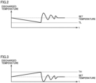
- Fig. 2 is a diagram depicting an example of the thermo-OFF operation when the air conditioning device is in the cooling operation.
- the air conditioning device In the cooling operation, the air conditioning device has excess capability for a load. This lowers a discharged temperature discharged from the air conditioning device. As the discharged temperature reaches a lower reference value limit TL, the first indoor unit 20a or the second indoor unit 20b performs the thermo-OFF operation. As a result, the frequency of the compressor 10 is reduced as well in order to prevent a rapid decrease in low pressure. Subsequently, the discharged temperature increases rapidly and hunt, after which it converges to a set temperature set by a remote control.
- Fig. 3 is a diagram depicting an example of the thermo-OFF operation when the air conditioning device is in a heating operation.
- the air conditioning device In the heating operation, the air conditioning device has excess capability for a load. This increases a discharged temperature discharged from the air conditioning device. As the discharged temperature reaches an upper reference value limit TH, the first indoor unit 20a or the second indoor unit 20b performs the thermo-OFF operation. Subsequently, the discharged temperature increases rapidly and hunt, after which it converges to the set temperature set by the remote control.
- the data storage device 71 stores data for each time t, the data representing the set temperature, the temperatures detected by the intake thermistors 7a and 7b, the temperatures detected by the discharge thermistors 8a and 8b, and whether one of the indoor units 20a and 20b performs the thermo-OFF operation.
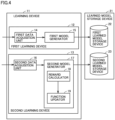
- Fig. 4 is a diagram depicting a configuration of the learning device 11.
- the learning device 11 includes a first learning device 12 and a second learning device 13.
- the learned model storage device 21 includes a first learned model storage device 22 and a second learned model storage device 23.
- the first learned model storage device 22 stores a first learned model.
- Fig. 5 is a diagram for illustrating the first learned model according to Embodiment 1.
- the first learned model according to Embodiment 1 is a model for outputting a prediction, made from a factor, as to whether one of the indoor units 20a and 20b performs the thermo-OFF operation during a future period of time, the factor including the set temperature, the temperatures detected by the intake thermistors 7a and 7b, and the temperatures detected by the discharge thermistors 8a and 8b during a past period of time.
- the second learned model storage device 23 stores a second learned model.
- Fig. 6 is a diagram for illustrating the second learned model according to Embodiment 1.
- the second learned model according to Embodiment 1 is a model for outputting an action from a state, the action including a target degree of superheat, a target degree of supercooling, a set frequency of the compressor 10, a target refrigerant evaporating temperature, and a target refrigerant condensing temperature, the state including the set temperature, the temperatures detected by the intake thermistors 7a and 7b, and the temperatures detected by the discharge thermistors 8a and 8b.
- the first learning device 12 includes a first data acquisition unit 14 and a first model generator 15.
- Fig. 7 is a diagram for illustrating an example of acquisition of first learning data when the air conditioning device is in the cooling operation.
- Fig. 8 is a diagram for illustrating an example of acquisition of the first learning data when the air conditioning device is in the heating operation.
- the first data acquisition unit 14 obtains the first learning data from the data storage device 71, the first learning data including (i) factor data including the set temperature, the temperatures detected by the intake thermistors 7a and 7b, and the temperatures detected by the discharge thermistors 8a and 8b during a first time period (11 through t1 + ⁇ Tx) and (ii) predictive data as to whether one of the indoor units 20a and 20b performs the thermo-OFF operation during a second time period (11 + ⁇ Tx through t1 + ⁇ Ty) later in time than the first time period.
- the first data acquisition unit 14 obtains multiple first learning data items by varying t1.
- the first model generator 15 uses the first learning data obtained by the first data acquisition unit 14, the first model generator 15 generates a first learned model for outputting a prediction, made from a factor, as to whether one of the indoor units 20a and 20b performs the thermo-OFF operation during a future period of time, the factor including the set temperature, the temperatures detected by the intake thermistors 7a and 7b, and the temperatures detected by the discharge thermistors 8a and 8b during a past period of time.
- the first model generator 15 stores the first learned model into the first learned model storage device 22.
- the first model generator 15 may use a well-known learning algorithm such as supervised learning, unsupervised learning, or reinforcement learning.
- supervised learning unsupervised learning
- reinforcement learning By way of example, description is now set forth where a neural network is applied to learning algorithm.
- Fig. 9 is a diagram depicting a configuration of the neural network.
- the first model generator 15 performs what is called supervised learning, in accordance with a neural network model, thereby learning a prediction, made from a factor, as to whether one of the indoor units 20a and 20b performs the thermo-OFF operation during a future period of time, the factor including the set temperature, the temperatures detected by the intake thermistors 7a and 7b, and the temperatures detected by the discharge thermistors 8a and 8b during a past period of time.
- the supervised learning refers to an approach in which the first learning device 12 is provided with a data set (the first learning data) of input and a result (label), and the first learning device 12 thereby learns features in the first learning data and infers a result from the input.
- the neural network consists of an input layer which includes multiple neurons; an intermediate layer (a hidden layer) which includes multiple neurons; and an output layer which includes multiple neurons.
- the intermediate layer may be one layer, or two or more layers.
- the neural network is a three-layer neural network
- the values of the inputs are weighed by a weight W1 (w11 through w16) and then input to intermediate layers (Y1 through Y2) where the results are weighed by a weight W2 (w21 through w26), and then output through output layers (Z1 through Z3).
- the result of this output depends on the values of the weights W1 and W2.
- the neural network generates a first learned model by what is called supervised learning, in accordance with the first learning data obtained by the first data acquisition unit 14. From the set temperature, the temperatures detected by the intake thermistors 7a and 7b, and the temperatures detected by the discharge thermistors 8a and 8b during a past period of time, the first learned model outputs a prediction as to whether one of the indoor units 20a and 20b performs the thermo-OFF operation during a future period of time.
- the neural network learns by: providing the input layers with the set temperature, the temperatures detected by the intake thermistors 7a and 7b, and the temperatures detected by the discharge thermistors 8a and 8b during a past period of time; and adjusting the weights W1 and W2 so that results of outputs from the output layers approach the prediction (a ground truth) as to whether one of the indoor units 20a and 20b performs the thermo-OFF operation within a future period of time.
- the first model generator 15 learns as described above, thereby generating and outputting a learned model to the first learned model storage device 22.
- Fig. 10 is a flowchart depicting a first learning procedure performed by the first learning device 12.
- the first data acquisition unit 14 obtains the first learning data from the data storage device 71.
- the first learning data includes (i) the factor data including the set temperature, the temperatures detected by the intake thermistors 7a and 7b, and the temperatures detected by the discharge thermistors 8a and 8b during the first time period (11 through t1 + ⁇ Tx), and (ii) the predictive data as to whether one of the indoor units 20a and 20b performs the thermo-OFF operation during the second time period (11 + ⁇ Tx through t1 + ⁇ Ty) later in time than the first time period.
- the first data acquisition unit 14 obtains multiple first learning data items by varying t1.
- step b2 using the first learning data obtained by the first data acquisition unit 14, the first model generator 15 generates the first learned model for outputting the prediction, made from a factor, as to whether one of the indoor units 20a and 20b performs the thermo-OFF operation within a future period of time, the factor including the set temperature, the temperatures detected by the intake thermistors 7a and 7b, and the temperatures detected by the discharge thermistors 8a and 8b during a past period of time.
- step b3 the first model generator 15 stores the first learned model into the first learned model storage device 22.
- the second learning device 13 includes a second data acquisition unit 16 and a second model generator 17.
- the second data acquisition unit 16 obtains second learning data including a state and an action in the state, the state including a set temperature, temperatures detected by the intake thermistors 7a and 7b, and temperatures detected by the discharge thermistors 8a and 8b, the action including a target degree of superheat, a target degree of supercooling, a set frequency of the compressor 10, a target refrigerant evaporating temperature, and a target refrigerant condensing temperature.
- the second model generator 17 uses the second learning data obtained by the second data acquisition unit 16, the second model generator 17 generates a second learned model for outputting an action from a state, the action including a target degree of superheat, a target degree of supercooling, a set frequency of the compressor 10, a target refrigerant evaporating temperature, and a target refrigerant condensing temperature, the state including a set temperature, temperatures detected by the intake thermistors 7a and 7b, and temperatures detected by the discharge thermistors 8a and 8b.
- the second model generator 17 stores the second learned model into the second learned model storage device 23.
- the second model generator 17 may use a well-known learning algorithm such as reinforcement learning.
- reinforcement learning an agent (actor) within a certain environment observes the current state (parameters of the environment) and determines an action to be taken. The action by the agent dynamically changes the environment, and the agent is provided with a reward in response to the changes in the environment. The agent repeats this process to learn a most rewarded course of action.
- Q-learning or temporal-difference (TD) learning can be used.
- a general update formula for the action value function Q (s, a) is represented by: Q s t a t ⁇ Q s t a t + ⁇ r t + 1 + ⁇ max a Q s t + 1 a ⁇ Q s t a t
- st denotes a state of the environment at the time t
- the action at changes the state to st + 1.
- a reward that the agent can receive due to the changes in state is represented by rt + 1, ⁇ denotes a discount factor, and ⁇ denotes a learning coefficient.
- the state st is the set temperature, the temperatures detected by the intake thermistors 7a and 7b, and temperatures detected by the discharge thermistors 8a and 20b.
- the action at is the target degree of superheat, the target degree of supercooling, the set frequency of the compressor 10, the target refrigerant evaporating temperature, and the target refrigerant condensing temperature.
- the first learning device 12 learns the best action at in the state st at the time t.
- the update formula denoted by Formula (1) yields an increased value of the action value function Q, and, otherwise, yields a reduced value of the action value function Q.
- the update formula updates the action value function Q (s, a) so that the value of the action value function Q for the action a at the time t approaches a best action value at the time t + 1. This causes the best action value in a certain environment to sequentially propagate to action values in previous environments.
- the second model generator 17 includes a reward calculator 18 and a function updater 19.
- the reward calculator 18 calculates a reward, based on an action and a state, the action including a target degree of superheat, a target degree of supercooling, a set frequency of the compressor 10, a target refrigerant evaporating temperature, and a target refrigerant condensing temperature, the state including a set temperature, temperatures detected by the intake thermistors 7a and 7b, and temperatures detected by the discharge thermistors 8a and 8b.
- the reward calculator 18 calculates a reward r, based on a difference between the set temperature and a discharged air temperature.
- the discharged air temperature can be one of or an average of the temperatures detected by the discharge thermistors 8a and 8b.
- the reward calculator 18 increases the reward r (e.g., gives a reward "1”) if the difference between the set temperature and the discharged air temperature decreases.
- the reward calculator 18, reduces the reward r (e.g., gives a reward "-1") if the difference between the set temperature and the discharged air temperature increases.
- the function updater 19 updates a function for determining an action including a target degree of superheat, a target degree of supercooling, a set frequency of the compressor 10, a target refrigerant evaporating temperature, and a target refrigerant condensing temperature, and outputs the function to the second learned model storage device 23.
- the function updater 19 uses the action value function Q (st, at) represented by Formula (1), as the function for calculating an action including a target degree of superheat, a target degree of supercooling, a set frequency of the compressor 10, a target refrigerant evaporating temperature, and a target refrigerant condensing temperature.
- the first learning device 12 repeatedly learns as described above.
- the second learned model storage device 23 stores the action value function Q (st, at) updated by the function updater 19, that is, the second learned model.
- Fig. 11 is a flowchart depicting the second learning procedure performed by the second learning device 13.
- the second data acquisition unit 16 obtains the second learning data which includes a state and an action in the state, the state including a set temperature, temperatures detected by the intake thermistors 7a and 7b, and temperatures detected by the discharge thermistors 8a and 8b, the action including a target degree of superheat, a target degree of supercooling, a set frequency of the compressor 10, a target refrigerant evaporating temperature, and a target refrigerant condensing temperature.
- step d2 the second model generator 17 calculates a reward, based on the second learning data. Specifically, the reward calculator 18 determines whether to increase or reduce the reward, based on a difference between the set temperature and the discharged air temperature.
- step S103 If the reward calculator 18 determines to increase the reward, the process proceeds to step S103. If the reward calculator 18 determines to reduce the reward, the process proceeds to step S104.
- step d3 the reward calculator 18 increases the reward.
- step d4 the reward calculator 18 reduces the reward.
- step d5 the function updater 19 updates the action value function Q (st, at) represented by Formula (1) and stored in the second learned model storage device 23, based on the reward calculated by the reward calculator 18.
- the second learning device 13 repeats the steps d1 through d5 stated above, and stores a generated action value function Q (st, at) as the second learned model.
- Fig. 12 is a diagram depicting a configuration of the inference device 31.
- the inference device 31 includes a first inference device 32 and a second inference device 33.
- the first inference device 32 includes a first data acquisition unit 34 and a first inference unit 35.
- the first data acquisition unit 34 obtains the factor data including the set temperature, the temperatures detected by the intake thermistors 7a and 7b, and the temperatures detected by the discharge thermistors 8a and 8b during a past period of time.
- the past period of time can be a time period (t0 - ⁇ Tx through t0), where the current time is t0.
- the first inference unit 35 inputs the factor data obtained by the first data acquisition unit 34 to the first learned model stored in the first learned model storage device 22, and outputs the prediction as to whether one of the indoor units 20a and 20b performs the thermo-OFF operation during a future period of time.
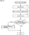
- Fig. 13 is a flowchart depicting the first inferring procedure performed by the first inference device 32.
- step c1 the first data acquisition unit 34 obtains the factor data including the set temperature, the temperatures detected by the intake thermistors 7a and 7b, and the temperatures detected by the discharge thermistors 8a and 8b during a past period of time.
- the first inference unit 35 inputs the factor data obtained by the first data acquisition unit 34 to the first learned model stored in the first learned model storage device 22, and outputs the prediction as to whether one of the indoor units 20a and 20b performs the thermo-OFF operation during a future period of time.
- step c4 if one of the indoor units 20a and 20b is predicted to perform the thermo-OFF operation during a future period of time, the process proceeds to step c5. The process ends if none of the indoor units 20a and 20b is predicted to perform the thermo-OFF operation during a future period of time.
- step c5 the second inference device 33 performs an inference process, which is described next.
- the second inference device 33 includes a second data acquisition unit 36 and a second inference unit 37.
- the second data acquisition unit 36 obtains a state including the set temperature, the temperatures detected by the intake thermistors 7a and 7b, and the temperatures detected by the discharge thermistors 8a and 8b.
- the second inference unit 37 uses the second learned model stored in the second learned model storage device 23, the second inference unit 37 infers an action from the state obtained by the second data acquisition unit 36, the action including a target degree of superheat, a target degree of supercooling, a set frequency of the compressor 10, a target refrigerant evaporating temperature, and a target refrigerant condensing temperature.
- the second inference unit 37 reads the action value function Q (st, at) from the second learned model storage device 23, as a second learned model.
- the second inference unit 37 obtains an action at in response to a state st, based on the action value function Q (s, a), the action at including the target degree of superheat, the target degree of supercooling, the set frequency of the compressor 10, the target refrigerant evaporating temperature, and the target refrigerant condensing temperature, the state st including the set temperature, the temperatures detected by the intake thermistors 7a and 7b, and the temperatures detected by the discharge thermistors 8a and 8b.
- the main controller 51 controls the air conditioning device, based on the action at including the target degree of superheat output from the second inference unit 37, the target degree of supercooling, the set frequency of the compressor 10, the target refrigerant evaporating temperature, and the target refrigerant condensing temperature.
- the main controller 51 controls the electronic expansion valves 4a and 4b so that the degree of superheat of the liquid refrigerant immediately after passing through the indoor heat exchangers 3a and 3b results in the target degree of superheat.
- the main controller 51 controls the electronic expansion valves 4a and 4b so that the degree of supercooling of the liquid refrigerant immediately after passing through the indoor heat exchangers 3a and 3b results in the target degree of supercooling.
- Fig. 14 is a flowchart depicting a second inferring procedure performed by the second inference device 33.
- step e1 the second data acquisition unit 36 obtains a state including the set temperature, the temperatures detected by the intake thermistors 7a and 7b, and the temperatures detected by the discharge thermistors 8a and 8b.
- step e2 using the second learned model stored in the second learned model storage device 23, the second inference unit 37 infers an action from the state obtained by the second data acquisition unit 36, the action including a target degree of superheat, a target degree of supercooling, a set frequency of the compressor 10, a target refrigerant evaporating temperature, and a target refrigerant condensing temperature.
- step e3 the second inference unit 37 outputs the target degree of superheat, the target degree of supercooling, the set frequency of the compressor 10, the target refrigerant evaporating temperature, and the target refrigerant condensing temperature to the main controller 51.
- step e4 the main controller 51 controls the air conditioning device, based on the target degree of superheat, the target degree of supercooling, the set frequency of the compressor 10, the target refrigerant evaporating temperature, and the target refrigerant condensing temperature.
- Fig. 15 is a diagram depicting an example of a first inference, a second inference, and an air-conditioning control when the air conditioning device is in the cooling operation.
- Fig. 16 is a diagram depicting an example of the first inference, the second inference, and the air-conditioning control when the air conditioning device is in the heating operation.
- the first inference device 32 at a time ta, inputs the factor data during a past period of time (ta - ⁇ Tx through ta) to the first learned model, thereby predicting that one of the indoor units 20a and 20b performs the thermo-OFF operation during a future period of time (ta through ta + ⁇ Tx).
- the second inference device uses the second learned model stored in the second learned model storage device 23, the second inference device, at and after the time ta, infers an action from a state, the action including a target degree of superheat, a target degree of supercooling, a set frequency of the compressor 10, a target refrigerant evaporating temperature, and a target refrigerant condensing temperature, the state including a set temperature, temperatures detected by the intake thermistors 7a and 7b, and temperatures detected by the discharge thermistors 8a and 8b.
- the main controller 51 controls the air conditioning device, based on the target degree of superheat, the target degree of supercooling, the set frequency of the compressor 10, the target refrigerant evaporating temperature, and the target refrigerant condensing temperature. This prevents the discharged temperature from reaching the lower reference value limit TL when the air conditioning device is in the cooling operation. Thus, the discharged temperature reaches the set temperature, without the first indoor unit 20a or the second indoor unit 20b performing the thermo-OFF operation. Since the discharged temperature does not reach the upper reference value limit TH when the air conditioning device is in the heating operation, the discharged temperature reaches the set temperature, without the first indoor unit 20a or the second indoor unit 20b performing the thermo-OFF operation.
- the air conditioning device outputs the prediction, made from a factor, as to whether one of the indoor units 20a and 20b performs the thermo-OFF operation during a future period of time, the factor including the set temperature, the temperatures detected by the intake thermistors 7a and 7b, and the temperatures detected by the discharge thermistors 8a and 8b during a past period of time. This allows predicting that each indoor unit performs the thermo-OFF operation in the air conditioning device which includes multiple indoor units capable of the thermo-OFF operation.
- the air conditioning device further outputs an action from a state, the action including a target degree of superheat, a target degree of supercooling, a set frequency of the compressor 10, a target refrigerant evaporating temperature, and a target refrigerant condensing temperature, the state including a set temperature, temperatures detected by the intake thermistors 7a and 7b, and temperatures detected by the discharge thermistors 8a and 8b.
- a state including a set temperature, temperatures detected by the intake thermistors 7a and 7b, and temperatures detected by the discharge thermistors 8a and 8b.
- Fig. 17 is a diagram for illustrating a first learned model according to Embodiment 2.
- the first learned model according to Embodiment 2 is a model for outputting a prediction, made from a factor, as to whether one of indoor units 20a and 20b performs a thermo-OFF operation during a future period of time, the factor including a set temperature, temperatures detected by intake thermistors 7a and 7b, and temperatures detected by discharge thermistors 8a and 8b during a past period of time and a forecast of the outdoor air temperature and a forecast of weather conditions during a future period of time.
- the forecast of the outdoor air temperature and the forecast of weather conditions during a future period of time can be, for example, forecasts for a period of time, such as within ten minutes or within an hour from the present time, which are obtained through the Internet, for example.
- Fig. 18 is a diagram for illustrating a second learned model according to Embodiment 2.
- the second learned model according to Embodiment 2 is a model for outputting an action from a state, the action including a target degree of superheat, a target degree of supercooling, a set frequency of a compressor 10, a target refrigerant evaporating temperature, and a target refrigerant condensing temperature, the state including a set temperature, temperatures detected by intake thermistors 7a and 7b, and temperatures detected by discharge thermistors 8a and 8b.
- a first learning device 12 is now described.
- a first data acquisition unit 14 obtains first learning data, which includes (i) factor data including the set temperature, the temperatures detected by the intake thermistors 7a and 7b, and the temperatures detected by the discharge thermistors 8a and 8b during a first time period (11 through t1 + ⁇ Tx) and a forecast of the outdoor air temperature and a forecast of weather conditions during a second time period (11 + ⁇ Tx through t1 + ⁇ Ty) later in time than the first time period, and (ii) predictive data as to whether one of the indoor units 20a and 20b performs the thermo-OFF operation during the second time period (11 + ⁇ Tx through t1 + ⁇ Ty).
- the first data acquisition unit 14 obtains multiple first learning data items by varying t1.
- a first model generator 15 uses the first learning data obtained by the first data acquisition unit 14, a first model generator 15 generates the first learned model for outputting the prediction, made from a factor, as to whether one of the indoor units 20a and 20b performs the thermo-OFF operation within a future period of time, the factor including the set temperature, the temperatures detected by the intake thermistors 7a and 7b, and the temperatures detected by the discharge thermistors 8a and 8b during a past period of time and a forecast of the outdoor air temperature and a forecast of weather conditions during a future period of time.
- the first model generator 15 stores the first learned model into a first learned model storage device 22.
- a second learning device 13 is now described.
- a second data acquisition unit 16 obtains second learning data which includes a state and an action in the state, the state including a set temperature, temperatures detected by the intake thermistors 7a and 7b, and temperatures detected by the discharge thermistors 8a and 8b, the action including a target degree of superheat, a target degree of supercooling, a set frequency of the compressor 10, a target refrigerant evaporating temperature, and a target refrigerant condensing temperature.
- a second model generator 17 uses the second learning data obtained by the second data acquisition unit 16, a second model generator 17 generates the second learned model for outputting an action from a state, the action including a target degree of superheat, a target degree of supercooling, a set frequency of the compressor 10, a target refrigerant evaporating temperature, and a target refrigerant condensing temperature, the state including a set temperature, temperatures detected by the intake thermistors 7a and 7b, and temperatures detected by the discharge thermistors 8a and 8b.
- a reward calculator 18 calculates a reward, based on the action including the target degree of superheat, the target degree of supercooling, the set frequency of the compressor 10, the target refrigerant evaporating temperature, and the target refrigerant condensing temperature, and the state including the set temperature, the temperatures detected by the intake thermistors 7a and 7b, and the temperatures detected by the discharge thermistors 8a and 8b.
- the reward calculator 18 calculates a reward r, based on a difference between the set temperature and the discharged air temperature.
- a function updater 19 updates a function for determining an action including a target degree of superheat, a target degree of supercooling, a set frequency of the compressor 10, a target refrigerant evaporating temperature, and a target refrigerant condensing temperature, and outputs the function to the second learned model storage device 23.
- a first inference device 32 is now described.
- a first data acquisition unit 34 obtains factor data including the set temperature, the temperatures detected by the intake thermistors 7a and 7b, and the temperatures detected by the discharge thermistors 8a and 8b during a past period of time and a forecast of the outdoor air temperature and a forecast of weather conditions during a future period of time.
- a first inference unit 35 inputs the factor data obtained by the first data acquisition unit 34 to the first learned model stored in the first learned model storage device 22, and outputs a prediction as to whether one of the indoor units 20a and 20b performs the thermo-OFF operation during a future period of time.
- a second inference device 33 is now described.
- a second data acquisition unit 36 obtains a state including the set temperature, the temperatures detected by the intake thermistors 7a and 7b, and the temperatures detected by the discharge thermistors 8a and 8b.
- a second inference unit 37 uses the second learned model stored in the second learned model storage device 23, to infer an action from the state obtained by the second data acquisition unit 36, the action including a target degree of superheat, a target degree of supercooling, a set frequency of the compressor 10, a target refrigerant evaporating temperature, and a target refrigerant condensing temperature.
- the second inference unit 37 reads an action value function Q (st, at) from the second learned model storage device 23 as the second learned model.
- the second inference unit 37 obtains an action at based on the action value function Q (s, a), the action at including the target degree of superheat, the target degree of supercooling, the set frequency of the compressor 10, the target refrigerant evaporating temperature, and the target refrigerant condensing temperature.
- a main controller 51 controls an air conditioning device, based on the target degree of superheat, the target degree of supercooling, the set frequency of the compressor 10, the target refrigerant evaporating temperature, and the target refrigerant condensing temperature.
- the discharged air temperature can be stabilized, without being subject to the weather.
- Fig. 19 is a diagram for illustrating a first learned model according to Embodiment 3.
- the first learned model according to Embodiment 3 is a model for outputting a prediction, made from a factor, as to whether one of indoor units 20a and 20b performs a thermo-OFF operation during a future period of time, the factor including a set temperature, temperatures detected by intake thermistors 7a and 7b, and temperatures detected by discharge thermistors 8a and 8b during a past period of time and a forecast of the outdoor air temperature, a forecast of the outdoor air humidity, and a forecast of weather conditions during a future period of time.
- the forecast of the outdoor air temperature, the forecast of the outdoor air humidity, and the forecast of weather conditions during a future period of time can be, for example, forecasts for a period of time, such as within ten minutes or within an hour from the present time, which are obtained through the Internet, for example.
- Fig. 20 is a diagram for illustrating a second learned model according to Embodiment 3.
- the second learned model according to Embodiment 3 is a model for outputting an action from a state, the action including a target degree of superheat, a set frequency of a compressor 10, a target refrigerant evaporating temperature, and a target humidity, the state including a set temperature, temperatures detected by intake thermistors 7a and 7b, and temperatures detected by discharge thermistors 8a and 8b.
- a first learning device 12 is now described.
- a first data acquisition unit 14 obtains first learning data which includes (i) factor data including the set temperature, the temperatures detected by the intake thermistors 7a and 7b, and the temperatures detected by the discharge thermistors 8a and 8b during a first time period (11 through t1 + ⁇ Tx) and a forecast of the outdoor air temperature, a forecast of the outdoor air humidity, and a forecast of weather conditions during a second time period (11 + ⁇ Tx through t1 + ⁇ Ty) later in time than the first time period, and (ii) predictive data as to whether one of the indoor units 20a and 20b performs the thermo-OFF operation during the second time period (11 + ⁇ Tx through t1 + ⁇ Ty).
- the first data acquisition unit 14 obtains multiple first learning data items by varying t1.
- a first model generator 15 uses the first learning data obtained by the first data acquisition unit 14, a first model generator 15 generates the first learned model for outputting the prediction, made from a factor, as to whether one of the indoor units 20a and 20b performs the thermo-OFF operation within a future period of time, the factor including the set temperature, the temperatures detected by the intake thermistors 7a and 7b, and the temperatures detected by the discharge thermistors 8a and 8b during a past period of time and a forecast of the outdoor air temperature, a forecast of the outdoor air humidity, and a forecast of weather conditions during a future period of time.
- the first model generator 15 stores the first learned model into a first learned model storage device 22.
- a second learning device 13 is now described.
- a second data acquisition unit 16 obtains second learning data which includes a state and an action in the state, the state including a set temperature, temperatures detected by the intake thermistors 7a and 7b, and temperatures detected by the discharge thermistors 8a and 8b, the action including a target degree of superheat, a set frequency of the compressor 10 of an outdoor apparatus 2, a target refrigerant evaporating temperature, and a target humidity.
- a second model generator 17 uses the second learning data obtained by the second data acquisition unit 16, a second model generator 17 generates the second learned model for outputting an action from a state, the action including a target degree of supercooling, a set frequency of the compressor 10, a target refrigerant evaporating temperature, and a target humidity, the state including a set temperature, temperatures detected by the intake thermistors 7a and 7b, and temperatures detected by the discharge thermistors 8a and 8b.
- a reward calculator 18 calculates a reward, based on the action including the target degree of superheat, the target degree of supercooling, the set frequency of the compressor 10, the target refrigerant evaporating temperature, and the target refrigerant condensing temperature, and the state including the set temperature, the temperatures detected by the intake thermistors 7a and 7b, and the temperatures detected by the discharge thermistors 8a and 8b.
- the reward calculator 18 calculates a reward r, based on a difference between the set temperature and the discharged air temperature.
- a function updater 19 updates a function for determining an action including a target degree of superheat, a target degree of supercooling, a set frequency of the compressor 10, a target refrigerant evaporating temperature, and a target refrigerant condensing temperature, and outputs the function to the second learned model storage device 23.
- a first inference device 32 is now described.
- a first data acquisition unit 34 obtains factor data including the set temperature, the temperatures detected by the intake thermistors 7a and 7b, and the temperatures detected by the discharge thermistors 8a and 8b during a past period of time and a forecast of the outdoor air temperature and a forecast of weather conditions during a future period of time.
- a first inference unit 35 inputs the factor data obtained by the first data acquisition unit 34 to the first learned model stored in the first learned model storage device 22, and outputs a prediction as to whether one of the indoor units 20a and 20b performs the thermo-OFF operation during a future period of time.
- a second inference device 33 is now described.
- a second data acquisition unit 36 obtains a state including the set temperature, the temperatures detected by the intake thermistors 7a and 7b, and the temperatures detected by the discharge thermistors 8a and 8b.
- a second inference unit 37 uses the second learned model stored in the second learned model storage device 23 to infer an action from the state obtained by the second data acquisition unit 36, the action including a target degree of superheat, a set frequency of the compressor 10, a target refrigerant evaporating temperature, and a target humidity.
- the second inference unit 37 reads an action value function Q (st, at) from the second learned model storage device 23 as the second learned model.
- the second inference unit 37 obtains an action at based on the action value function Q (s, a), the action at including the target degree of superheat, the set frequency of the compressor 10, the target refrigerant evaporating temperature, and the target humidity.
- a main controller 51 controls an air conditioning device, based on the target degree of superheat, the set frequency of the compressor 10, and the target refrigerant evaporating temperature.
- the main controller 51 also controls the cooling operation or the dehumidification operation so that the indoor humidity reaches the target humidity.
- the operation of the air conditioning device can be automatically switched to the dehumidification operation when the humidity is increased, such as when the weather forecast indicates the chance of rain.
Landscapes
- Engineering & Computer Science (AREA)
- Signal Processing (AREA)
- Physics & Mathematics (AREA)
- Fuzzy Systems (AREA)
- Mathematical Physics (AREA)
- Chemical & Material Sciences (AREA)
- Combustion & Propulsion (AREA)
- Mechanical Engineering (AREA)
- General Engineering & Computer Science (AREA)
- Air Conditioning Control Device (AREA)
Abstract
Description
- The present disclosure relates to an air conditioning device and a learning device of an air conditioning device.
- An air conditioning device is known which includes multiple indoor units and allows each indoor unit to perform a thermo-OFF operation.
- For example, the air conditioning device disclosed in
PTL 1 has a refrigerant circuit in which multiple indoor units individually having an indoor heat exchanger and an indoor expansion valve and an outdoor unit having an outdoor expansion valve are connected by a liquid refrigerant communication tube and a gas refrigerant communication tube. The indoor units perform the thermo-OFF operations independent of each other. - PTL 1:
Japanese Patent Laying-Open No. 2020-169809 - In the air conditioning device disclosed in
PTL 1, it is determined, for each indoor unit, whether the indoor unit performs the thermo-OFF operation. Since each indoor unit performs the thermo-OFF operation autonomously, if a certain indoor unit performs the thermo-OFF operation, the outdoor apparatus needs to reduce the circulation volume of the refrigerant for that indoor unit in order to keep the high pressure and the low pressure of the compressor within an operating range. As a result, the circulation volume of the refrigerant of the entire air conditioning device rapidly decreases, ending up with perturbation of the temperature of the drawn-in air. - Therefore, an object of the present disclosure is to provide an air conditioning device which includes multiple indoor units capable of a thermo-OFF operation and allows stabilized temperature of the drawn-in air, and a learning device of an air conditioning device.
- The present disclosure is an air conditioning device which includes an indoor apparatus and an outdoor apparatus. The outdoor apparatus includes a compressor and an outdoor heat exchanger. The indoor apparatus includes a plurality of indoor units and a fan. Each indoor unit includes a controller, an indoor heat exchanger, an electronic expansion valve, an intake thermistor for detecting a drawn-in air temperature, and a discharge thermistor for detecting a discharged air temperature, and performs a thermo-OFF operation when the temperature detected by the discharge thermistor reaches a reference value. The air conditioning device further includes a first inference device to infer whether any of the plurality of indoor units performs a thermo-OFF operation during a future period of time, from a factor including a set temperature, temperatures detected by the plurality of intake thermistors, and temperatures detected by the plurality of discharge thermistors during a past period of time.
- The present disclosure is a learning device of an air conditioning device which includes an indoor apparatus and an outdoor apparatus. The outdoor apparatus includes a compressor and an outdoor heat exchanger. The indoor apparatus includes a plurality of indoor units and a fan. Each indoor unit includes a controller, an indoor heat exchanger, an electronic expansion valve, an intake thermistor that detects a drawn-in air temperature, and a discharge thermistor that detects a discharged air temperature, and the indoor unit performs a thermo-OFF operation when the temperature detected by the discharge thermistor reaches a reference value. The learning device of the air conditioning device includes: a first data acquisition unit to obtain first learning data including (i) factor data including a set temperature, temperatures detected by the plurality of intake thermistors, and temperatures detected by the plurality of discharge thermistors during a first time period, and (ii) predictive data indicating whether any of the plurality of indoor units performs a thermo-OFF operation during a second time period later in time than the first time period; and a first model generator to generate, using the first learning data, a first learned model for outputting a prediction as to whether any of the plurality of indoor units performs a thermo-OFF operation during a future period of time from a factor including a set temperature, temperatures detected by the plurality of intake thermistors, and temperatures detected by the plurality of discharge thermistors during a past period of time.
- According to the present disclosure, the temperature of the drawn-in air can be stabilized in the air conditioning device which includes multiple indoor units capable of the thermo-OFF operation.
-
-
Fig. 1 is a diagram depicting a configuration of an air conditioning device according to an embodiment. -
Fig. 2 is a diagram depicting an example of a thermo-OFF operation when the air conditioning device is in a cooling operation. -
Fig. 3 is a diagram depicting an example of the thermo-OFF operation when the air conditioning device is in a heating operation. -
Fig. 4 is a diagram depicting a configuration of alearning device 11. -
Fig. 5 is a diagram for illustrating a first learned model according to Embodiment 1. -
Fig. 6 is a diagram for illustrating a second learned model according to Embodiment 1. -
Fig. 7 is a diagram for illustrating an example of acquisition of first learning data when the air conditioning device is in the cooling operation. -
Fig. 8 is a diagram for illustrating an example of acquisition of the first learning data when the air conditioning device is in the heating operation. -
Fig. 9 is a diagram depicting a configuration of a neural network. -
Fig. 10 is a flowchart depicting a first learning procedure performed by afirst learning device 12. -
Fig. 11 is a flowchart depicting a second learning procedure performed by asecond learning device 13. -
Fig. 12 is a diagram depicting a configuration of aninference device 31. -
Fig. 13 is a flowchart depicting a first inferring procedure performed by afirst inference device 32. -
Fig. 14 is a flowchart depicting a second inferring procedure performed by asecond inference device 33. -
Fig. 15 is a diagram depicting an example of a first inference, a second inference, and an air-conditioning control when the air conditioning device is in the cooling operation. -
Fig. 16 is a diagram depicting an example of the first inference, the second inference, and the air-conditioning control when the air conditioning device is in the heating operation. -
Fig. 17 is a diagram for illustrating a first learned model according to Embodiment 2. -
Fig. 18 is a diagram for illustrating a second learned model according to Embodiment 2. -
Fig. 19 is a diagram for illustrating a first learned model according to Embodiment 3. -
Fig. 20 is a diagram for illustrating a second learned model according to Embodiment 3. -
Fig. 21 is a diagram depicting a hardware configuration of alearning device 11, aninference device 31, or amain controller 51. -
Fig. 1 is a diagram depicting a configuration of an air conditioning device according to an embodiment. - An air conditioning device includes an
outdoor apparatus 2, anindoor apparatus 1, alearning device 11, a learnedmodel storage device 21, aninference device 31, adata storage device 71, and amain controller 51. - The
outdoor apparatus 2 includes acompressor 10 and anoutdoor heat exchanger 9. - The
indoor apparatus 1 includes a firstindoor unit 20a, a secondindoor unit 20b, and afan 5. - The first
indoor unit 20a includes afirst controller 6a, a firstindoor heat exchanger 3a, a firstelectronic expansion valve 4a, afirst intake thermistor 7a for detecting a drawn-in air temperature into the firstindoor unit 20a, and afirst discharge thermistor 8a for detecting a discharged air temperature from the firstindoor unit 20a. Thefirst controller 6a is connected to the firstindoor heat exchanger 3a, the firstelectronic expansion valve 4a, thefirst intake thermistor 7a, thefirst discharge thermistor 8a, and thefan 5. - The second
indoor unit 20b includes asecond controller 6b, a secondindoor heat exchanger 3b, a secondelectronic expansion valve 4b, asecond intake thermistor 7b for detecting a drawn-in air temperature into the secondindoor unit 20b, and asecond discharge thermistor 8b for detecting a discharged air temperature from the secondindoor unit 20b. Thesecond controller 6b is connected to the secondindoor heat exchanger 3b, the secondelectronic expansion valve 4b, thesecond intake thermistor 7b, thesecond discharge thermistor 8b, and thefan 5. -
Fig. 1 shows a flow of a refrigerant when the air conditioning device is in a cooling operation. - As the temperature detected by the
first discharge thermistor 8a reaches a reference value, the firstindoor unit 20a performs a thermo-OFF operation. In the thermo-OFF operation, thefirst controller 6a, for example, sets the firstelectronic expansion valve 4a fully closed and notifies theoutdoor apparatus 2 that the operation of the firstindoor unit 20a is switched to the thermo-OFF operation. Theoutdoor apparatus 2 lowers the upper limit for the frequency of thecompressor 10 and lowers the actual operation frequency of thecompressor 10. - As the temperature detected by the
second discharge thermistor 8b reaches a reference value, the secondindoor unit 20b performs a thermo-OFF operation. In the thermo-OFF operation, thesecond controller 6b, for example, sets the secondelectronic expansion valve 4b fully closed, stops thefan 5, and notifies theoutdoor apparatus 2 that the operation of the secondindoor unit 20b is switched to the thermo-OFF operation. Theoutdoor apparatus 2 lowers the upper limit for the frequency of thecompressor 10 and lowers the actual operation frequency of thecompressor 10. -
Fig. 2 is a diagram depicting an example of the thermo-OFF operation when the air conditioning device is in the cooling operation. - In the cooling operation, the air conditioning device has excess capability for a load. This lowers a discharged temperature discharged from the air conditioning device. As the discharged temperature reaches a lower reference value limit TL, the first
indoor unit 20a or the secondindoor unit 20b performs the thermo-OFF operation. As a result, the frequency of thecompressor 10 is reduced as well in order to prevent a rapid decrease in low pressure. Subsequently, the discharged temperature increases rapidly and hunt, after which it converges to a set temperature set by a remote control. -
Fig. 3 is a diagram depicting an example of the thermo-OFF operation when the air conditioning device is in a heating operation. - In the heating operation, the air conditioning device has excess capability for a load. This increases a discharged temperature discharged from the air conditioning device. As the discharged temperature reaches an upper reference value limit TH, the first
indoor unit 20a or the secondindoor unit 20b performs the thermo-OFF operation. Subsequently, the discharged temperature increases rapidly and hunt, after which it converges to the set temperature set by the remote control. - The
data storage device 71 stores data for each time t, the data representing the set temperature, the temperatures detected by theintake thermistors discharge thermistors indoor units -
Fig. 4 is a diagram depicting a configuration of thelearning device 11. - The
learning device 11 includes afirst learning device 12 and asecond learning device 13. The learnedmodel storage device 21 includes a first learnedmodel storage device 22 and a second learnedmodel storage device 23. - The first learned
model storage device 22 stores a first learned model. -
Fig. 5 is a diagram for illustrating the first learned model according toEmbodiment 1. - The first learned model according to
Embodiment 1 is a model for outputting a prediction, made from a factor, as to whether one of theindoor units intake thermistors discharge thermistors - The second learned
model storage device 23 stores a second learned model. -
Fig. 6 is a diagram for illustrating the second learned model according toEmbodiment 1. - The second learned model according to
Embodiment 1 is a model for outputting an action from a state, the action including a target degree of superheat, a target degree of supercooling, a set frequency of thecompressor 10, a target refrigerant evaporating temperature, and a target refrigerant condensing temperature, the state including the set temperature, the temperatures detected by theintake thermistors discharge thermistors - The
first learning device 12 includes a firstdata acquisition unit 14 and afirst model generator 15. -
Fig. 7 is a diagram for illustrating an example of acquisition of first learning data when the air conditioning device is in the cooling operation.Fig. 8 is a diagram for illustrating an example of acquisition of the first learning data when the air conditioning device is in the heating operation. - The first
data acquisition unit 14 obtains the first learning data from thedata storage device 71, the first learning data including (i) factor data including the set temperature, the temperatures detected by theintake thermistors discharge thermistors indoor units data acquisition unit 14 obtains multiple first learning data items by varying t1. - Using the first learning data obtained by the first
data acquisition unit 14, thefirst model generator 15 generates a first learned model for outputting a prediction, made from a factor, as to whether one of theindoor units intake thermistors discharge thermistors first model generator 15 stores the first learned model into the first learnedmodel storage device 22. - The
first model generator 15 may use a well-known learning algorithm such as supervised learning, unsupervised learning, or reinforcement learning. By way of example, description is now set forth where a neural network is applied to learning algorithm. -
Fig. 9 is a diagram depicting a configuration of the neural network. - For example, the
first model generator 15 performs what is called supervised learning, in accordance with a neural network model, thereby learning a prediction, made from a factor, as to whether one of theindoor units intake thermistors discharge thermistors first learning device 12 is provided with a data set (the first learning data) of input and a result (label), and thefirst learning device 12 thereby learns features in the first learning data and infers a result from the input. - The neural network consists of an input layer which includes multiple neurons; an intermediate layer (a hidden layer) which includes multiple neurons; and an output layer which includes multiple neurons. The intermediate layer may be one layer, or two or more layers.
- For example, if the neural network is a three-layer neural network, as multiple inputs are input to input layers (X1 through X3), the values of the inputs are weighed by a weight W1 (w11 through w16) and then input to intermediate layers (Y1 through Y2) where the results are weighed by a weight W2 (w21 through w26), and then output through output layers (Z1 through Z3). The result of this output depends on the values of the weights W1 and W2.
- The neural network generates a first learned model by what is called supervised learning, in accordance with the first learning data obtained by the first
data acquisition unit 14. From the set temperature, the temperatures detected by theintake thermistors discharge thermistors indoor units - In other words, the neural network learns by: providing the input layers with the set temperature, the temperatures detected by the
intake thermistors discharge thermistors indoor units - The
first model generator 15 learns as described above, thereby generating and outputting a learned model to the first learnedmodel storage device 22. -
Fig. 10 is a flowchart depicting a first learning procedure performed by thefirst learning device 12. - In
step b 1, the firstdata acquisition unit 14 obtains the first learning data from thedata storage device 71. The first learning data includes (i) the factor data including the set temperature, the temperatures detected by theintake thermistors discharge thermistors indoor units data acquisition unit 14 obtains multiple first learning data items by varying t1. - In step b2, using the first learning data obtained by the first
data acquisition unit 14, thefirst model generator 15 generates the first learned model for outputting the prediction, made from a factor, as to whether one of theindoor units intake thermistors discharge thermistors - In step b3, the
first model generator 15 stores the first learned model into the first learnedmodel storage device 22. - The
second learning device 13 includes a seconddata acquisition unit 16 and asecond model generator 17. - The second
data acquisition unit 16 obtains second learning data including a state and an action in the state, the state including a set temperature, temperatures detected by theintake thermistors discharge thermistors compressor 10, a target refrigerant evaporating temperature, and a target refrigerant condensing temperature. - Using the second learning data obtained by the second
data acquisition unit 16, thesecond model generator 17 generates a second learned model for outputting an action from a state, the action including a target degree of superheat, a target degree of supercooling, a set frequency of thecompressor 10, a target refrigerant evaporating temperature, and a target refrigerant condensing temperature, the state including a set temperature, temperatures detected by theintake thermistors discharge thermistors second model generator 17 stores the second learned model into the second learnedmodel storage device 23. - The
second model generator 17 may use a well-known learning algorithm such as reinforcement learning. By way of example, description is now set forth where the neural network is applied to reinforcement learning. In the reinforcement learning, an agent (actor) within a certain environment observes the current state (parameters of the environment) and determines an action to be taken. The action by the agent dynamically changes the environment, and the agent is provided with a reward in response to the changes in the environment. The agent repeats this process to learn a most rewarded course of action. A representative approach, Q-learning or temporal-difference (TD) learning, can be used. For example, with Q-learning, a general update formula for the action value function Q (s, a) is represented by:

where st denotes a state of the environment at the time t, and at denotes an action at the time t. The action at changes the state to st + 1. A reward that the agent can receive due to the changes in state is represented by rt + 1, γ denotes a discount factor, and α denotes a learning coefficient. Note that γ falls in a range of 0 < γ ≤ 1, and α falls in a range of 0 < α ≤ 1. The state st is the set temperature, the temperatures detected by theintake thermistors discharge thermistors compressor 10, the target refrigerant evaporating temperature, and the target refrigerant condensing temperature. With Q-learning, thefirst learning device 12 learns the best action at in the state st at the time t. - If the value of the action value function Q for an action a yielding a highest Q value at the time t + 1 is greater than the value of the action value function Q for an action a carried out at the time t, the update formula denoted by Formula (1) yields an increased value of the action value function Q, and, otherwise, yields a reduced value of the action value function Q. Stated differently, the update formula updates the action value function Q (s, a) so that the value of the action value function Q for the action a at the time t approaches a best action value at the
time t + 1. This causes the best action value in a certain environment to sequentially propagate to action values in previous environments. - As described above, to generate the second learned model by the reinforcement learning, the
second model generator 17 includes areward calculator 18 and afunction updater 19. - The
reward calculator 18 calculates a reward, based on an action and a state, the action including a target degree of superheat, a target degree of supercooling, a set frequency of thecompressor 10, a target refrigerant evaporating temperature, and a target refrigerant condensing temperature, the state including a set temperature, temperatures detected by theintake thermistors discharge thermistors reward calculator 18 calculates a reward r, based on a difference between the set temperature and a discharged air temperature. The discharged air temperature can be one of or an average of the temperatures detected by thedischarge thermistors reward calculator 18 increases the reward r (e.g., gives a reward "1") if the difference between the set temperature and the discharged air temperature decreases. Thereward calculator 18, on the other hand, reduces the reward r (e.g., gives a reward "-1") if the difference between the set temperature and the discharged air temperature increases. - In accordance with the reward calculated by the
reward calculator 18, thefunction updater 19 updates a function for determining an action including a target degree of superheat, a target degree of supercooling, a set frequency of thecompressor 10, a target refrigerant evaporating temperature, and a target refrigerant condensing temperature, and outputs the function to the second learnedmodel storage device 23. With Q-learning, for example, thefunction updater 19 uses the action value function Q (st, at) represented by Formula (1), as the function for calculating an action including a target degree of superheat, a target degree of supercooling, a set frequency of thecompressor 10, a target refrigerant evaporating temperature, and a target refrigerant condensing temperature. - The
first learning device 12 repeatedly learns as described above. The second learnedmodel storage device 23 stores the action value function Q (st, at) updated by thefunction updater 19, that is, the second learned model. -
Fig. 11 is a flowchart depicting the second learning procedure performed by thesecond learning device 13. - In step d1, the second
data acquisition unit 16 obtains the second learning data which includes a state and an action in the state, the state including a set temperature, temperatures detected by theintake thermistors discharge thermistors compressor 10, a target refrigerant evaporating temperature, and a target refrigerant condensing temperature. - In step d2, the
second model generator 17 calculates a reward, based on the second learning data. Specifically, thereward calculator 18 determines whether to increase or reduce the reward, based on a difference between the set temperature and the discharged air temperature. - If the
reward calculator 18 determines to increase the reward, the process proceeds to step S103. If thereward calculator 18 determines to reduce the reward, the process proceeds to step S104. - In step d3, the
reward calculator 18 increases the reward. - In step d4, the
reward calculator 18 reduces the reward. - In step d5, the
function updater 19 updates the action value function Q (st, at) represented by Formula (1) and stored in the second learnedmodel storage device 23, based on the reward calculated by thereward calculator 18. - The
second learning device 13 repeats the steps d1 through d5 stated above, and stores a generated action value function Q (st, at) as the second learned model. -
Fig. 12 is a diagram depicting a configuration of theinference device 31. - The
inference device 31 includes afirst inference device 32 and asecond inference device 33. - The
first inference device 32 includes a firstdata acquisition unit 34 and afirst inference unit 35. - The first
data acquisition unit 34 obtains the factor data including the set temperature, the temperatures detected by theintake thermistors discharge thermistors - The
first inference unit 35 inputs the factor data obtained by the firstdata acquisition unit 34 to the first learned model stored in the first learnedmodel storage device 22, and outputs the prediction as to whether one of theindoor units -
Fig. 13 is a flowchart depicting the first inferring procedure performed by thefirst inference device 32. - In step c1, the first
data acquisition unit 34 obtains the factor data including the set temperature, the temperatures detected by theintake thermistors discharge thermistors - In steps c2 and c3, the
first inference unit 35 inputs the factor data obtained by the firstdata acquisition unit 34 to the first learned model stored in the first learnedmodel storage device 22, and outputs the prediction as to whether one of theindoor units - In step c4, if one of the
indoor units indoor units - In step c5, the
second inference device 33 performs an inference process, which is described next. - The
second inference device 33 includes a seconddata acquisition unit 36 and asecond inference unit 37. - The second
data acquisition unit 36 obtains a state including the set temperature, the temperatures detected by theintake thermistors discharge thermistors - Using the second learned model stored in the second learned
model storage device 23, thesecond inference unit 37 infers an action from the state obtained by the seconddata acquisition unit 36, the action including a target degree of superheat, a target degree of supercooling, a set frequency of thecompressor 10, a target refrigerant evaporating temperature, and a target refrigerant condensing temperature. - For example, the
second inference unit 37 reads the action value function Q (st, at) from the second learnedmodel storage device 23, as a second learned model. Thesecond inference unit 37 obtains an action at in response to a state st, based on the action value function Q (s, a), the action at including the target degree of superheat, the target degree of supercooling, the set frequency of thecompressor 10, the target refrigerant evaporating temperature, and the target refrigerant condensing temperature, the state st including the set temperature, the temperatures detected by theintake thermistors discharge thermistors - The
main controller 51 controls the air conditioning device, based on the action at including the target degree of superheat output from thesecond inference unit 37, the target degree of supercooling, the set frequency of thecompressor 10, the target refrigerant evaporating temperature, and the target refrigerant condensing temperature. - For example, when the air conditioning device is in the cooling operation, the
main controller 51 controls theelectronic expansion valves indoor heat exchangers main controller 51 controls theelectronic expansion valves indoor heat exchangers -
Fig. 14 is a flowchart depicting a second inferring procedure performed by thesecond inference device 33. - In step e1, the second
data acquisition unit 36 obtains a state including the set temperature, the temperatures detected by theintake thermistors discharge thermistors - In step e2, using the second learned model stored in the second learned
model storage device 23, thesecond inference unit 37 infers an action from the state obtained by the seconddata acquisition unit 36, the action including a target degree of superheat, a target degree of supercooling, a set frequency of thecompressor 10, a target refrigerant evaporating temperature, and a target refrigerant condensing temperature. - In step e3, the
second inference unit 37 outputs the target degree of superheat, the target degree of supercooling, the set frequency of thecompressor 10, the target refrigerant evaporating temperature, and the target refrigerant condensing temperature to themain controller 51. - In step e4, the
main controller 51 controls the air conditioning device, based on the target degree of superheat, the target degree of supercooling, the set frequency of thecompressor 10, the target refrigerant evaporating temperature, and the target refrigerant condensing temperature. -
Fig. 15 is a diagram depicting an example of a first inference, a second inference, and an air-conditioning control when the air conditioning device is in the cooling operation.Fig. 16 is a diagram depicting an example of the first inference, the second inference, and the air-conditioning control when the air conditioning device is in the heating operation. - The
first inference device 32, at a time ta, inputs the factor data during a past period of time (ta - ΔTx through ta) to the first learned model, thereby predicting that one of theindoor units - Using the second learned model stored in the second learned
model storage device 23, the second inference device, at and after the time ta, infers an action from a state, the action including a target degree of superheat, a target degree of supercooling, a set frequency of thecompressor 10, a target refrigerant evaporating temperature, and a target refrigerant condensing temperature, the state including a set temperature, temperatures detected by theintake thermistors discharge thermistors - The
main controller 51 controls the air conditioning device, based on the target degree of superheat, the target degree of supercooling, the set frequency of thecompressor 10, the target refrigerant evaporating temperature, and the target refrigerant condensing temperature. This prevents the discharged temperature from reaching the lower reference value limit TL when the air conditioning device is in the cooling operation. Thus, the discharged temperature reaches the set temperature, without the firstindoor unit 20a or the secondindoor unit 20b performing the thermo-OFF operation. Since the discharged temperature does not reach the upper reference value limit TH when the air conditioning device is in the heating operation, the discharged temperature reaches the set temperature, without the firstindoor unit 20a or the secondindoor unit 20b performing the thermo-OFF operation. - As described above, the air conditioning device according to the present embodiment outputs the prediction, made from a factor, as to whether one of the
indoor units intake thermistors discharge thermistors - The air conditioning device according to the present embodiment further outputs an action from a state, the action including a target degree of superheat, a target degree of supercooling, a set frequency of the
compressor 10, a target refrigerant evaporating temperature, and a target refrigerant condensing temperature, the state including a set temperature, temperatures detected by theintake thermistors discharge thermistors -
Fig. 17 is a diagram for illustrating a first learned model according toEmbodiment 2. - The first learned model according to
Embodiment 2 is a model for outputting a prediction, made from a factor, as to whether one ofindoor units intake thermistors discharge thermistors -
Fig. 18 is a diagram for illustrating a second learned model according toEmbodiment 2. - The second learned model according to
Embodiment 2 is a model for outputting an action from a state, the action including a target degree of superheat, a target degree of supercooling, a set frequency of acompressor 10, a target refrigerant evaporating temperature, and a target refrigerant condensing temperature, the state including a set temperature, temperatures detected byintake thermistors discharge thermistors - A
first learning device 12 is now described. - A first
data acquisition unit 14 obtains first learning data, which includes (i) factor data including the set temperature, the temperatures detected by theintake thermistors discharge thermistors indoor units data acquisition unit 14 obtains multiple first learning data items by varying t1. - Using the first learning data obtained by the first
data acquisition unit 14, afirst model generator 15 generates the first learned model for outputting the prediction, made from a factor, as to whether one of theindoor units intake thermistors discharge thermistors first model generator 15 stores the first learned model into a first learnedmodel storage device 22. - A
second learning device 13 is now described. - A second
data acquisition unit 16 obtains second learning data which includes a state and an action in the state, the state including a set temperature, temperatures detected by theintake thermistors discharge thermistors compressor 10, a target refrigerant evaporating temperature, and a target refrigerant condensing temperature. - Using the second learning data obtained by the second
data acquisition unit 16, asecond model generator 17 generates the second learned model for outputting an action from a state, the action including a target degree of superheat, a target degree of supercooling, a set frequency of thecompressor 10, a target refrigerant evaporating temperature, and a target refrigerant condensing temperature, the state including a set temperature, temperatures detected by theintake thermistors discharge thermistors - A
reward calculator 18 calculates a reward, based on the action including the target degree of superheat, the target degree of supercooling, the set frequency of thecompressor 10, the target refrigerant evaporating temperature, and the target refrigerant condensing temperature, and the state including the set temperature, the temperatures detected by theintake thermistors discharge thermistors reward calculator 18 calculates a reward r, based on a difference between the set temperature and the discharged air temperature. - In accordance with the reward calculated by the
reward calculator 18, afunction updater 19 updates a function for determining an action including a target degree of superheat, a target degree of supercooling, a set frequency of thecompressor 10, a target refrigerant evaporating temperature, and a target refrigerant condensing temperature, and outputs the function to the second learnedmodel storage device 23. - A
first inference device 32 is now described. - A first
data acquisition unit 34 obtains factor data including the set temperature, the temperatures detected by theintake thermistors discharge thermistors - A
first inference unit 35 inputs the factor data obtained by the firstdata acquisition unit 34 to the first learned model stored in the first learnedmodel storage device 22, and outputs a prediction as to whether one of theindoor units - A
second inference device 33 is now described. - A second
data acquisition unit 36 obtains a state including the set temperature, the temperatures detected by theintake thermistors discharge thermistors - Using the second learned model stored in the second learned
model storage device 23, asecond inference unit 37 infers an action from the state obtained by the seconddata acquisition unit 36, the action including a target degree of superheat, a target degree of supercooling, a set frequency of thecompressor 10, a target refrigerant evaporating temperature, and a target refrigerant condensing temperature. - For example, the
second inference unit 37 reads an action value function Q (st, at) from the second learnedmodel storage device 23 as the second learned model. In response to a state st including the set temperature, the temperatures detected by theintake thermistors discharge thermistors second inference unit 37 obtains an action at based on the action value function Q (s, a), the action at including the target degree of superheat, the target degree of supercooling, the set frequency of thecompressor 10, the target refrigerant evaporating temperature, and the target refrigerant condensing temperature. - Similarly to
Embodiment 1, amain controller 51 controls an air conditioning device, based on the target degree of superheat, the target degree of supercooling, the set frequency of thecompressor 10, the target refrigerant evaporating temperature, and the target refrigerant condensing temperature. - According to the present embodiment, the discharged air temperature can be stabilized, without being subject to the weather.
-
Fig. 19 is a diagram for illustrating a first learned model according to Embodiment 3. - The first learned model according to Embodiment 3 is a model for outputting a prediction, made from a factor, as to whether one of
indoor units intake thermistors discharge thermistors -
Fig. 20 is a diagram for illustrating a second learned model according to Embodiment 3. - The second learned model according to Embodiment 3 is a model for outputting an action from a state, the action including a target degree of superheat, a set frequency of a
compressor 10, a target refrigerant evaporating temperature, and a target humidity, the state including a set temperature, temperatures detected byintake thermistors discharge thermistors - A
first learning device 12 is now described. - A first
data acquisition unit 14 obtains first learning data which includes (i) factor data including the set temperature, the temperatures detected by theintake thermistors discharge thermistors indoor units data acquisition unit 14 obtains multiple first learning data items by varying t1. - Using the first learning data obtained by the first
data acquisition unit 14, afirst model generator 15 generates the first learned model for outputting the prediction, made from a factor, as to whether one of theindoor units intake thermistors discharge thermistors first model generator 15 stores the first learned model into a first learnedmodel storage device 22. - A
second learning device 13 is now described. - A second
data acquisition unit 16 obtains second learning data which includes a state and an action in the state, the state including a set temperature, temperatures detected by theintake thermistors discharge thermistors compressor 10 of anoutdoor apparatus 2, a target refrigerant evaporating temperature, and a target humidity. - Using the second learning data obtained by the second
data acquisition unit 16, asecond model generator 17 generates the second learned model for outputting an action from a state, the action including a target degree of supercooling, a set frequency of thecompressor 10, a target refrigerant evaporating temperature, and a target humidity, the state including a set temperature, temperatures detected by theintake thermistors discharge thermistors - A
reward calculator 18 calculates a reward, based on the action including the target degree of superheat, the target degree of supercooling, the set frequency of thecompressor 10, the target refrigerant evaporating temperature, and the target refrigerant condensing temperature, and the state including the set temperature, the temperatures detected by theintake thermistors discharge thermistors reward calculator 18 calculates a reward r, based on a difference between the set temperature and the discharged air temperature. - In accordance with the reward calculated by the
reward calculator 18, afunction updater 19 updates a function for determining an action including a target degree of superheat, a target degree of supercooling, a set frequency of thecompressor 10, a target refrigerant evaporating temperature, and a target refrigerant condensing temperature, and outputs the function to the second learnedmodel storage device 23. - A
first inference device 32 is now described. - A first
data acquisition unit 34 obtains factor data including the set temperature, the temperatures detected by theintake thermistors discharge thermistors - A
first inference unit 35 inputs the factor data obtained by the firstdata acquisition unit 34 to the first learned model stored in the first learnedmodel storage device 22, and outputs a prediction as to whether one of theindoor units - A
second inference device 33 is now described. - A second
data acquisition unit 36 obtains a state including the set temperature, the temperatures detected by theintake thermistors discharge thermistors - Using the second learned model stored in the second learned
model storage device 23, asecond inference unit 37 infers an action from the state obtained by the seconddata acquisition unit 36, the action including a target degree of superheat, a set frequency of thecompressor 10, a target refrigerant evaporating temperature, and a target humidity. - For example, the
second inference unit 37 reads an action value function Q (st, at) from the second learnedmodel storage device 23 as the second learned model. In response to a state st including the set temperature, the temperatures detected by theintake thermistors discharge thermistors second inference unit 37 obtains an action at based on the action value function Q (s, a), the action at including the target degree of superheat, the set frequency of thecompressor 10, the target refrigerant evaporating temperature, and the target humidity. - Similarly to
Embodiment 1, amain controller 51 controls an air conditioning device, based on the target degree of superheat, the set frequency of thecompressor 10, and the target refrigerant evaporating temperature. Themain controller 51 also controls the cooling operation or the dehumidification operation so that the indoor humidity reaches the target humidity. - According to the present embodiment, the operation of the air conditioning device can be automatically switched to the dehumidification operation when the humidity is increased, such as when the weather forecast indicates the chance of rain.
-
- (1) While the
learning device 11 and theinference device 31 are provided inside the air conditioning device, thelearning device 11 and theinference device 31 may be separate from the air conditioning device and connected to the air conditioning device through a network. Furthermore, thelearning device 11 and theinference device 31 may reside on a cloud server. - (2)
Fig. 21 is a diagram depicting a hardware configuration of thelearning device 11, theinference device 31, or themain controller 51.
Operations corresponding to the operations of thelearning device 11, theinference device 31, and themain controller 51 can be configured in hardware or software for digital circuits. If the functions of thelearning device 11, theinference device 31, and themain controller 51 are implemented using software, thelearning device 11, theinference device 31, and themain controller 51 can include, for example, aprocessor 5002 and amemory 5001 that are connected together by abus 5003 as shown inFig. 21 , and theprocessor 5002 can execute programs stored in thememory 5001. - (3) While the embodiments have been described with reference to the supervised learning being applied to the learning algorithm for use by the
first model generator 15, the present disclosure is not limited thereto. Besides the supervised learning, reinforcement learning, unsupervised learning, or semi-supervised learning, etc. is also applicable to the learning algorithm. While the embodiments have been described with reference to the reinforcement learning being applied to the learning algorithm for use by thesecond model generator 17, the present disclosure is not limited thereto. Besides the reinforcement learning, supervised learning, unsupervised learning, or semi-supervised learning, etc. is also applicable to the learning algorithm. - (4) The
first model generator 15 and thesecond model generator 17 may generate the first learned model and the second learned model in accordance with the first learning data and the second learning data, respectively, created at multiple air conditioning devices. Thefirst model generator 15 and thesecond model generator 17 may obtain the first learning data and the second learning data from multiple air conditioning devices that are used in a same area, or obtain the first learning data and the second learning data from multiple air conditioning devices operating independently in different areas. The air conditioning device that collects the first learning data and the second learning data can be added to or excluded from a target. Furthermore, the first learning data and the second learning data of a certain air conditioning device may be used to generate a first learned model and a second learned model, and the first learned model and the second learned model may be updated (re-learned) using first learning data and a second learned model of a different air conditioning device. - (5) Deep learning that learns extraction of features themselves can be used as the learning algorithms that use the
first model generator 15 and thesecond model generator 17, and the machine learning may be performed in accordance with other well-known method, for example, genetic programming, functional and logic programming, or a support vector machine. - (6) In the embodiment, the
first inference unit 35 uses the first learned model to output the prediction, made from the factor data obtained by the firstdata acquisition unit 34, as to whether one of theindoor units first inference unit 35 may output the prediction as to whether one of theindoor units data acquisition unit 34, based on a rule-based inference or an incident-based inference.
Thesecond inference unit 37 according toEmbodiment 1 uses the second learned model to infer an action from the state obtained by the seconddata acquisition unit 36, the action including a target degree of superheat, a target degree of supercooling, a set frequency of thecompressor 10, a target refrigerant evaporating temperature, and a target refrigerant condensing temperature. However, the present disclosure is not limited thereto. For example, thesecond inference unit 37 may infer, from the state obtained by the seconddata acquisition unit 36 based on the rule-based inference or the incident-based inference, an action including a target degree of superheat, a target degree of supercooling, a set frequency of thecompressor 10, a target refrigerant evaporating temperature, and a target refrigerant condensing temperature. The same is true forEmbodiments 2 and 3. - (7) While the factor of the first learned model according to the embodiments described above includes a set temperature during a past period of time, the present disclosure is not limited thereto. A factor of the first learned model may be a difference between the set temperature during a past period of time and each of the temperatures detected by multiple discharge thermistors during a past period of time. While the state of the second learned model according to the embodiments described above includes a set temperature, the present disclosure is not limited thereto. A factor of the second learned model may be a difference between the set temperature and each of the temperatures detected by multiple discharge thermistors.
- (8) While the embodiments described above include two indoor units, the present disclosure is not limited thereto. There may be three or more indoor units.
- The presently disclosed embodiments above should be considered illustrative in all aspects and do not limit the present disclosure. The scope of the present disclosure is defined by the appended claims, rather than by the above description. All changes which come within the meaning and range of equivalency of the appended claims are intended to be embraced within their scope.
- 1 indoor apparatus; 2 outdoor apparatus; 3a first indoor heat exchanger; 3b second indoor heat exchanger; 4a first electronic expansion valve; 4b second electronic expansion valve; 5 fan; 6a first controller; 6b second controller; 7a first intake thermistor; 7b second intake thermistor; 8a first discharge thermistor; 8b second discharge thermistor; 9 outdoor heat exchanger; 10 compressor; 11 learning device; 12 first learning device; 13 second learning device; 14, 34 first data acquisition unit; 15 first model generator; 16, 36 second data acquisition unit; 17 second model generator; 18 reward calculator; 19 function updater; 20a first indoor unit; 20b second indoor unit; 21 learned model storage device; 22 first learned model storage device; 23 second learned model storage device; 31 inference device; 32 first inference device; 33 second inference device; 35 first inference unit; 37 second inference unit; 51 main controller; 71 data storage device; 5001 memory; 5002 processor; and 5003 bus.
Claims (15)
- An air conditioning device, comprising an indoor apparatus and an outdoor apparatus,the outdoor apparatus including a compressor and an outdoor heat exchanger,the indoor apparatus including a plurality of indoor units and a fan, whereineach indoor unit, among the plurality of indoor units, includes a controller, an indoor heat exchanger, an electronic expansion valve, an intake thermistor for detecting a drawn-in air temperature, and a discharge thermistor for detecting a discharged air temperature, wherein the indoor unit performs a thermo-OFF operation when a temperature detected by the discharge thermistor reaches a reference value,the air conditioning device further comprisinga first inference device to infer, from a factor, whether any of the plurality of indoor units performs a thermo-OFF operation during a future period of time, the factor including a set temperature, temperatures detected by a plurality of the intake thermistors, and temperatures detected by a plurality of the discharge thermistors during a past period of time.
- The air conditioning device according to claim 1, wherein
the first inference device includes:a first data acquisition unit that obtains factor data including a set temperature, temperatures detected by the plurality of intake thermistors, and temperatures detected by the plurality of discharge thermistors during a past period of time; anda first inference unit that inputs the factor data obtained by the first data acquisition unit to a first learned model and outputs a prediction as to whether any of the plurality of indoor units performs a thermo-OFF operation during a future period of time, the first learned model being a learned model for outputting a prediction, made from a factor, as to whether any of the plurality of indoor units performs a thermo-OFF operation during a future period of time, the factor including a set temperature, temperatures detected by the plurality of intake thermistors, and temperatures detected by the plurality of discharge thermistors during a past period of time. - The air conditioning device according to claim 2, whereinthe first data acquisition unit obtains the factor data further including a forecast of an outdoor air temperature and a forecast of weather conditions during a future period of time, andthe first inference unit inputs the factor data obtained by the first data acquisition unit to a first learned model, and outputs a prediction as to whether any of the plurality of indoor units performs a thermo-OFF operation during a future period of time, the first learned model being a learned model for outputting a prediction, made from a factor, as to whether any of the plurality of indoor units performs a thermo-OFF operation during a future period of time, the factor including a set temperature, temperatures detected by the plurality of intake thermistors, and temperatures detected by the plurality of discharge thermistors during a past period of time and a forecast of an outdoor air temperature and a forecast of weather conditions during a future period of time.
- The air conditioning device according to claim 2, whereinthe first data acquisition unit obtains the factor data further including a forecast of an outdoor air temperature, a forecast of an outdoor air humidity, and a forecast of weather conditions during a future period of time, andthe first inference unit inputs the factor data obtained by the first data acquisition unit to a first learned model, and outputs a prediction as to whether any of the plurality of indoor units performs a thermo-OFF operation during a future period of time, the first learned model being a learned model for inferring, from a factor, whether any of the plurality of indoor units performs a thermo-OFF operation during a future period of time, the factor including a set temperature, temperatures detected by the plurality of intake thermistors, and temperatures detected by the plurality of discharge thermistors during a past period of time and a forecast of an outdoor air temperature, a forecast of an outdoor air humidity, and a forecast of weather conditions during a future period of time.
- The air conditioning device according to claim 1, comprising:a second inference device to infer, when a prediction is output that one of the plurality of indoor units performs a thermo-OFF operation during a future period of time, a target degree of superheat, a target degree of supercooling, a set frequency of the compressor, a target refrigerant evaporating temperature, and a target refrigerant condensing temperature from a state including a set temperature, temperatures detected by the plurality of intake thermistors, and temperatures detected by the plurality of discharge thermistors; anda main controller to control the air conditioning device, based on a result of inference by the second inference device.
- The air conditioning device according to claim 5, wherein
the second inference device includes:a second data acquisition unit that obtains a state including a set temperature, temperatures detected by the plurality of intake thermistors, and temperatures detected by the plurality of discharge thermistors; anda second inference unit that infers, using a second learned model, an action from the state obtained by the second data acquisition unit, the action including a target degree of superheat, a target degree of supercooling, a set frequency of the compressor, a target refrigerant evaporating temperature, and a target refrigerant condensing temperature, the second learned model being a learned model for inferring an action from a state, the action including a target degree of superheat, a target degree of supercooling, a set frequency of the compressor, a target refrigerant evaporating temperature, and a target refrigerant condensing temperature, the state including a set temperature, temperatures detected by the plurality of intake thermistors, and temperatures detected by the plurality of discharge thermistors. - The air conditioning device according to claim 1, comprising:a second inference device to infer, when a prediction is output that any of the plurality of indoor units performs a thermo-OFF operation during a future period of time, a target degree of superheat, a set frequency of the compressor, a target refrigerant evaporating temperature, and a target humidity from a state including a set temperature, temperatures detected by the plurality of intake thermistors, and temperatures detected by the plurality of discharge thermistors; anda main controller to control the air conditioning device, based on a result of inference by the second inference device.
- The air conditioning device according to claim 7, wherein
the second inference device includes:a second data acquisition unit that obtains a state including a set temperature, temperatures detected by the plurality of intake thermistors, and temperatures detected by the plurality of discharge thermistors; anda second inference unit that infers, using a second learned model, an action from the state obtained by the second data acquisition unit, the action including a target degree of superheat, a set frequency of the compressor, a target refrigerant evaporating temperature, and a target humidity, the second learned model being a learned model for inferring an action from a state, the action including a target degree of superheat, a set frequency of the compressor, a target refrigerant evaporating temperature, and a target humidity, the state including a set temperature, temperatures detected by the plurality of intake thermistors, and temperatures detected by the plurality of discharge thermistors. - A learning device of an air conditioning device which includes an indoor apparatus and an outdoor apparatus,the outdoor apparatus including a compressor and an outdoor heat exchanger,the indoor apparatus including a plurality of indoor units and a fan, whereineach indoor unit, among the plurality of indoor units, includes a controller, an indoor heat exchanger, an electronic expansion valve, an intake thermistor for detecting a drawn-in air temperature, and a discharge thermistor for detecting a discharged air temperature, wherein the indoor unit performs a thermo-OFF operation when a temperature detected by the discharge thermistor reaches a reference value,the learning device, comprising:a first data acquisition unit to obtain first learning data including (i) factor data including a set temperature, temperatures detected by a plurality of the intake thermistors, and temperatures detected by a plurality of the discharge thermistors during a first time period, and (ii) predictive data as to whether any of the plurality of indoor units performs a thermo-OFF operation during a second time period later in time than the first time period; anda first model generator to generate, using the first learning data, a first learned model for outputting a prediction, made from a factor, as to whether any of the plurality of indoor units performs a thermo-OFF operation during a future period of time, the factor including a set temperature, temperatures detected by the plurality of intake thermistors, and temperatures detected by the plurality of discharge thermistors during a past period of time.
- The learning device of the air conditioning device according to claim 9, whereinthe first data acquisition unit obtains first learning data including the predictive data and the factor data further including a forecast of an outdoor air temperature and a forecast of weather conditions during a future period of time, andusing the first learning data, the first model generator generates a first learned model for outputting a prediction, made from a factor, as to whether any of the plurality of indoor units performs a thermo-OFF operation during a future period of time, the factor including a set temperature, temperatures detected by the plurality of intake thermistors, and temperatures detected by the plurality of discharge thermistors during a past period of time and a forecast of an outdoor air temperature and a forecast of weather conditions during a future period of time.
- The learning device of the air conditioning device according to claim 9, whereinthe first data acquisition unit obtains first learning data including the predictive data and the factor data further including a forecast of an outdoor air temperature, a forecast of an outdoor air humidity, and a forecast of weather conditions during a future period of time, andusing the first learning data, the first model generator generates a first learned model for outputting a prediction, made from a factor, as to whether any of the plurality of indoor units performs a thermo-OFF operation during a future period of time, the factor including a set temperature, temperatures detected by the plurality of intake thermistors, and temperatures detected by the plurality of discharge thermistors during a past period of time and a forecast of an outdoor air temperature, a forecast of an outdoor air humidity, and a forecast of weather conditions during a future period of time.
- The learning device of the air conditioning device according to claim 9, comprising:a second data acquisition unit to obtain second learning data including a state and an action in the state, the state including a set temperature, temperatures detected by the plurality of intake thermistors, and temperatures detected by the plurality of discharge thermistors, the action including a target degree of superheat, a target degree of supercooling, a set frequency of the compressor, a target refrigerant evaporating temperature, and a target refrigerant condensing temperature; anda second model generator to generate, using the second learning data, a second learned model for outputting an action from a state, the action including a target degree of superheat, a target degree of supercooling, a set frequency of the compressor, a target refrigerant evaporating temperature, and a target refrigerant condensing temperature, the state including a set temperature, temperatures detected by the plurality of intake thermistors, and temperatures detected by the plurality of discharge thermistors.
- The learning device of the air conditioning device according to claim 9, comprising:a second data acquisition unit to obtain second learning data including a state and an action in the state, the state including a set temperature, temperatures detected by the plurality of intake thermistors, and temperatures detected by the plurality of discharge thermistors, the action including a target degree of superheat, a set frequency of the compressor, a target refrigerant evaporating temperature, and a target humidity; anda second model generator to generate, using the second learning data, a second learned model for outputting an action from a state, the action including a target degree of superheat, a set frequency of the compressor, a target refrigerant evaporating temperature, and a target humidity, the state including a set temperature, the temperatures detected by the plurality of intake thermistors, and the temperatures detected by the plurality of discharge thermistors.
- The learning device of the air conditioning device according to any one of claims 9 to 13, wherein
the second model generator generates the second learned model by Q-learning. - The learning device of the air conditioning device according to claim 14, wherein
the second model generator increases a reward when a difference between the set temperature and a discharged air temperature decreases, and reduces a reward when a difference between the set temperature and the discharged air temperature increases.
Applications Claiming Priority (1)
| Application Number | Priority Date | Filing Date | Title |
|---|---|---|---|
| PCT/JP2020/041935 WO2022101989A1 (en) | 2020-11-10 | 2020-11-10 | Air conditioning device, and learning device of air conditioning device |
Publications (3)
| Publication Number | Publication Date |
|---|---|
| EP4246050A1 true EP4246050A1 (en) | 2023-09-20 |
| EP4246050A4 EP4246050A4 (en) | 2024-03-27 |
| EP4246050B1 EP4246050B1 (en) | 2025-10-22 |
Family
ID=81600887
Family Applications (1)
| Application Number | Title | Priority Date | Filing Date |
|---|---|---|---|
| EP20961517.8A Active EP4246050B1 (en) | 2020-11-10 | 2020-11-10 | Air conditioning device |
Country Status (2)
| Country | Link |
|---|---|
| EP (1) | EP4246050B1 (en) |
| WO (1) | WO2022101989A1 (en) |
Families Citing this family (2)
| Publication number | Priority date | Publication date | Assignee | Title |
|---|---|---|---|---|
| JPWO2024034110A1 (en) * | 2022-08-12 | 2024-02-15 | ||
| WO2025052607A1 (en) * | 2023-09-06 | 2025-03-13 | 三菱電機株式会社 | Ventilation system, learning device, and inference device |
Family Cites Families (9)
| Publication number | Priority date | Publication date | Assignee | Title |
|---|---|---|---|---|
| JP4141083B2 (en) * | 2000-04-20 | 2008-08-27 | 三洋電機株式会社 | Air conditioner |
| JP5672088B2 (en) * | 2010-03-31 | 2015-02-18 | ダイキン工業株式会社 | Air conditioning controller |
| US8996141B1 (en) * | 2010-08-26 | 2015-03-31 | Dunan Microstaq, Inc. | Adaptive predictive functional controller |
| JP6072424B2 (en) * | 2012-04-13 | 2017-02-01 | 三菱電機株式会社 | Air conditioner |
| CN105473354A (en) * | 2013-08-18 | 2016-04-06 | 森思博有限公司 | Power consumption assessment of an HVAC system |
| WO2016016913A1 (en) * | 2014-07-30 | 2016-02-04 | 三菱電機株式会社 | Air conditioning device |
| JP6790246B2 (en) * | 2017-04-27 | 2020-11-25 | 三菱電機株式会社 | Air conditioners, controls, air conditioners and programs |
| CN112840164B (en) | 2018-09-27 | 2023-01-17 | 大金工业株式会社 | Air Conditioning Units and Management Units |
| KR102170522B1 (en) * | 2018-10-18 | 2020-10-27 | 부산대학교 산학협력단 | Energy management system for exhibition hall considering environment and occupancy changes |
-
2020
- 2020-11-10 WO PCT/JP2020/041935 patent/WO2022101989A1/en not_active Ceased
- 2020-11-10 EP EP20961517.8A patent/EP4246050B1/en active Active
Also Published As
| Publication number | Publication date |
|---|---|
| EP4246050B1 (en) | 2025-10-22 |
| EP4246050A4 (en) | 2024-03-27 |
| WO2022101989A1 (en) | 2022-05-19 |
Similar Documents
| Publication | Publication Date | Title |
|---|---|---|
| Li et al. | Intelligent multi-zone residential HVAC control strategy based on deep reinforcement learning | |
| Fiducioso et al. | Safe contextual Bayesian optimization for sustainable room temperature PID control tuning | |
| Li et al. | A knowledge-guided and data-driven method for building HVAC systems fault diagnosis | |
| Wei et al. | Deep reinforcement learning for building HVAC control | |
| US20200279149A1 (en) | Method for reinforcement learning using virtual environment generated by deep learning | |
| US20190360711A1 (en) | Method and device for controlling power supply to heating, ventilating, and air-conditioning (hvac) system for building based on target temperature | |
| US9752791B2 (en) | Air-conditioning unit control device and air-conditioning unit control program for minimizing power consumption | |
| JP2018186693A (en) | Scalable flexibility control of distributed loads in the power grid | |
| US12510868B2 (en) | Building equipment energy management control system and control therefor | |
| EP4246050B1 (en) | Air conditioning device | |
| JP6937261B2 (en) | Air conditioning control device, air conditioning control method and computer program | |
| US20250093065A1 (en) | Learning device, air conditioning control system, inference device, air conditioning control device, and trained model generation method | |
| Zendehboudi et al. | Data-driven modeling of residential air source heat pump system for space heating: A. Zendehboudi, J. Zhao and X. Li | |
| Noh et al. | Development of a DNN model using calibrated simulation for the optimal control of HVAC systems | |
| JP7305041B2 (en) | Information processing equipment and air conditioning system | |
| Wang et al. | An environment-adaptive SAC-based HVAC control of single-zone residential and office buildings | |
| Mohebi et al. | Comparing different parameter identification techniques for optimal control of building energy systems | |
| Manoharan et al. | Learn to chill: Intelligent chiller scheduling using meta-learning and deep reinforcement learning | |
| JP7378497B2 (en) | Model sharing system, model management device, and air conditioner control device | |
| US20240167716A1 (en) | Information processing device and air conditioning system | |
| CN118729461A (en) | Air conditioning control method, device, medium and equipment | |
| Nishiguchi et al. | Data-driven optimal control for building energy conservation | |
| Kusiak et al. | Reheat optimization of the variable-air-volume box | |
| Khanghah et al. | SAC-Based Distributed Optimal Control of Generation Cost in DC Microgrids | |
| JP2020016992A (en) | Characteristic model automatic generation system and characteristic model automatic generation method |
Legal Events
| Date | Code | Title | Description |
|---|---|---|---|
| STAA | Information on the status of an ep patent application or granted ep patent |
Free format text: STATUS: THE INTERNATIONAL PUBLICATION HAS BEEN MADE |
|
| PUAI | Public reference made under article 153(3) epc to a published international application that has entered the european phase |
Free format text: ORIGINAL CODE: 0009012 |
|
| STAA | Information on the status of an ep patent application or granted ep patent |
Free format text: STATUS: REQUEST FOR EXAMINATION WAS MADE |
|
| 17P | Request for examination filed |
Effective date: 20230425 |
|
| AK | Designated contracting states |
Kind code of ref document: A1 Designated state(s): AL AT BE BG CH CY CZ DE DK EE ES FI FR GB GR HR HU IE IS IT LI LT LU LV MC MK MT NL NO PL PT RO RS SE SI SK SM TR |
|
| DAV | Request for validation of the european patent (deleted) | ||
| DAX | Request for extension of the european patent (deleted) | ||
| A4 | Supplementary search report drawn up and despatched |
Effective date: 20240222 |
|
| RIC1 | Information provided on ipc code assigned before grant |
Ipc: F24F 11/62 20180101ALI20240216BHEP Ipc: F24F 11/63 20180101ALI20240216BHEP Ipc: F24F 130/10 20180101ALI20240216BHEP Ipc: F24F 110/10 20180101ALI20240216BHEP Ipc: F24F 11/64 20180101AFI20240216BHEP |
|
| GRAP | Despatch of communication of intention to grant a patent |
Free format text: ORIGINAL CODE: EPIDOSNIGR1 |
|
| STAA | Information on the status of an ep patent application or granted ep patent |
Free format text: STATUS: GRANT OF PATENT IS INTENDED |
|
| INTG | Intention to grant announced |
Effective date: 20250605 |
|
| GRAS | Grant fee paid |
Free format text: ORIGINAL CODE: EPIDOSNIGR3 |
|
| GRAA | (expected) grant |
Free format text: ORIGINAL CODE: 0009210 |
|
| STAA | Information on the status of an ep patent application or granted ep patent |
Free format text: STATUS: THE PATENT HAS BEEN GRANTED |
|
| AK | Designated contracting states |
Kind code of ref document: B1 Designated state(s): AL AT BE BG CH CY CZ DE DK EE ES FI FR GB GR HR HU IE IS IT LI LT LU LV MC MK MT NL NO PL PT RO RS SE SI SK SM TR |
|
| REG | Reference to a national code |
Ref country code: CH Ref legal event code: F10 Free format text: ST27 STATUS EVENT CODE: U-0-0-F10-F00 (AS PROVIDED BY THE NATIONAL OFFICE) Effective date: 20251022 Ref country code: GB Ref legal event code: FG4D |
|
| REG | Reference to a national code |
Ref country code: DE Ref legal event code: R096 Ref document number: 602020061064 Country of ref document: DE |
|
| REG | Reference to a national code |
Ref country code: IE Ref legal event code: FG4D |
|
| PGFP | Annual fee paid to national office [announced via postgrant information from national office to epo] |
Ref country code: DE Payment date: 20251126 Year of fee payment: 6 |
|
| REG | Reference to a national code |
Ref country code: NL Ref legal event code: MP Effective date: 20251022 |
|
| PG25 | Lapsed in a contracting state [announced via postgrant information from national office to epo] |
Ref country code: NL Free format text: LAPSE BECAUSE OF FAILURE TO SUBMIT A TRANSLATION OF THE DESCRIPTION OR TO PAY THE FEE WITHIN THE PRESCRIBED TIME-LIMIT Effective date: 20251022 |
|
| PG25 | Lapsed in a contracting state [announced via postgrant information from national office to epo] |
Ref country code: ES Free format text: LAPSE BECAUSE OF FAILURE TO SUBMIT A TRANSLATION OF THE DESCRIPTION OR TO PAY THE FEE WITHIN THE PRESCRIBED TIME-LIMIT Effective date: 20251022 |
|
| REG | Reference to a national code |
Ref country code: LT Ref legal event code: MG9D |
|
| PG25 | Lapsed in a contracting state [announced via postgrant information from national office to epo] |
Ref country code: NO Free format text: LAPSE BECAUSE OF FAILURE TO SUBMIT A TRANSLATION OF THE DESCRIPTION OR TO PAY THE FEE WITHIN THE PRESCRIBED TIME-LIMIT Effective date: 20260122 |
|
| PG25 | Lapsed in a contracting state [announced via postgrant information from national office to epo] |
Ref country code: AT Free format text: LAPSE BECAUSE OF FAILURE TO SUBMIT A TRANSLATION OF THE DESCRIPTION OR TO PAY THE FEE WITHIN THE PRESCRIBED TIME-LIMIT Effective date: 20251022 Ref country code: HR Free format text: LAPSE BECAUSE OF FAILURE TO SUBMIT A TRANSLATION OF THE DESCRIPTION OR TO PAY THE FEE WITHIN THE PRESCRIBED TIME-LIMIT Effective date: 20251022 Ref country code: FI Free format text: LAPSE BECAUSE OF FAILURE TO SUBMIT A TRANSLATION OF THE DESCRIPTION OR TO PAY THE FEE WITHIN THE PRESCRIBED TIME-LIMIT Effective date: 20251022 |
|
| REG | Reference to a national code |
Ref country code: AT Ref legal event code: MK05 Ref document number: 1849442 Country of ref document: AT Kind code of ref document: T Effective date: 20251022 |
|
| PG25 | Lapsed in a contracting state [announced via postgrant information from national office to epo] |
Ref country code: RS Free format text: LAPSE BECAUSE OF FAILURE TO SUBMIT A TRANSLATION OF THE DESCRIPTION OR TO PAY THE FEE WITHIN THE PRESCRIBED TIME-LIMIT Effective date: 20260122 |
|
| PG25 | Lapsed in a contracting state [announced via postgrant information from national office to epo] |
Ref country code: IS Free format text: LAPSE BECAUSE OF FAILURE TO SUBMIT A TRANSLATION OF THE DESCRIPTION OR TO PAY THE FEE WITHIN THE PRESCRIBED TIME-LIMIT Effective date: 20260222 |
|
| PG25 | Lapsed in a contracting state [announced via postgrant information from national office to epo] |
Ref country code: PT Free format text: LAPSE BECAUSE OF FAILURE TO SUBMIT A TRANSLATION OF THE DESCRIPTION OR TO PAY THE FEE WITHIN THE PRESCRIBED TIME-LIMIT Effective date: 20260223 |
|
| PG25 | Lapsed in a contracting state [announced via postgrant information from national office to epo] |
Ref country code: PL Free format text: LAPSE BECAUSE OF FAILURE TO SUBMIT A TRANSLATION OF THE DESCRIPTION OR TO PAY THE FEE WITHIN THE PRESCRIBED TIME-LIMIT Effective date: 20251022 |
|
| PG25 | Lapsed in a contracting state [announced via postgrant information from national office to epo] |
Ref country code: LV Free format text: LAPSE BECAUSE OF FAILURE TO SUBMIT A TRANSLATION OF THE DESCRIPTION OR TO PAY THE FEE WITHIN THE PRESCRIBED TIME-LIMIT Effective date: 20251022 |