EP4246009B1 - Holster tensioner device - Google Patents
Holster tensioner device Download PDFInfo
- Publication number
- EP4246009B1 EP4246009B1 EP23161414.0A EP23161414A EP4246009B1 EP 4246009 B1 EP4246009 B1 EP 4246009B1 EP 23161414 A EP23161414 A EP 23161414A EP 4246009 B1 EP4246009 B1 EP 4246009B1
- Authority
- EP
- European Patent Office
- Prior art keywords
- holster
- tensioner
- handgun
- assembly
- set forth
- Prior art date
- Legal status (The legal status is an assumption and is not a legal conclusion. Google has not performed a legal analysis and makes no representation as to the accuracy of the status listed.)
- Active
Links
Images




Classifications
-
- F—MECHANICAL ENGINEERING; LIGHTING; HEATING; WEAPONS; BLASTING
- F41—WEAPONS
- F41C—SMALLARMS, e.g. PISTOLS, RIFLES; ACCESSORIES THEREFOR
- F41C33/00—Means for wearing or carrying smallarms
- F41C33/02—Holsters, i.e. cases for pistols having means for being carried or worn, e.g. at the belt or under the arm
- F41C33/0263—Holsters, i.e. cases for pistols having means for being carried or worn, e.g. at the belt or under the arm having a locking system for preventing unauthorized or accidental removal of the small arm from the holster
-
- F—MECHANICAL ENGINEERING; LIGHTING; HEATING; WEAPONS; BLASTING
- F16—ENGINEERING ELEMENTS AND UNITS; GENERAL MEASURES FOR PRODUCING AND MAINTAINING EFFECTIVE FUNCTIONING OF MACHINES OR INSTALLATIONS; THERMAL INSULATION IN GENERAL
- F16F—SPRINGS; SHOCK-ABSORBERS; MEANS FOR DAMPING VIBRATION
- F16F3/00—Spring units consisting of several springs, e.g. for obtaining a desired spring characteristic
- F16F3/02—Spring units consisting of several springs, e.g. for obtaining a desired spring characteristic with springs made of steel or of other material having low internal friction
-
- F—MECHANICAL ENGINEERING; LIGHTING; HEATING; WEAPONS; BLASTING
- F41—WEAPONS
- F41C—SMALLARMS, e.g. PISTOLS, RIFLES; ACCESSORIES THEREFOR
- F41C33/00—Means for wearing or carrying smallarms
- F41C33/02—Holsters, i.e. cases for pistols having means for being carried or worn, e.g. at the belt or under the arm
- F41C33/0236—Half-holsters covering by encircling only a part of the small arm, e.g. ghost-holsters
-
- F—MECHANICAL ENGINEERING; LIGHTING; HEATING; WEAPONS; BLASTING
- F16—ENGINEERING ELEMENTS AND UNITS; GENERAL MEASURES FOR PRODUCING AND MAINTAINING EFFECTIVE FUNCTIONING OF MACHINES OR INSTALLATIONS; THERMAL INSULATION IN GENERAL
- F16F—SPRINGS; SHOCK-ABSORBERS; MEANS FOR DAMPING VIBRATION
- F16F2238/00—Type of springs or dampers
- F16F2238/02—Springs
- F16F2238/022—Springs leaf-like, e.g. of thin, planar-like metal
-
- F—MECHANICAL ENGINEERING; LIGHTING; HEATING; WEAPONS; BLASTING
- F16—ENGINEERING ELEMENTS AND UNITS; GENERAL MEASURES FOR PRODUCING AND MAINTAINING EFFECTIVE FUNCTIONING OF MACHINES OR INSTALLATIONS; THERMAL INSULATION IN GENERAL
- F16F—SPRINGS; SHOCK-ABSORBERS; MEANS FOR DAMPING VIBRATION
- F16F2238/00—Type of springs or dampers
- F16F2238/02—Springs
- F16F2238/026—Springs wound- or coil-like
Definitions
- the holster 10 ( Figure 1 ) includes a holster body 20 that defines a chamber 22 for receiving the handgun 14.
- the holster 10 has an entranceway or opening 24 into the chamber 22 for allowing insertion of the handgun 14 into the holster.
- the holster body 20 has a bottom wall 26 and a top wall 27.
- the spring 50 extends in a force-transmitting relationship between the two end portions 32 and 34 of the tensioner body 30. Specifically, one end of the spring 50 is connected to the first spring loop 40, and the second end of the spring is connected to the second spring loop 42.
- the spring 50 thus is located generally inside of and parallel to the central portion 32 of the tensioner body 30.
- the spring 50 is a tension spring which resists elongation, that is, it resists movement of the two tensioner body end portions 32 and 24 away from each other.
- the spring 50 may be a compression spring, mounted outside the tensioner body 30.
- the outer side surface 38 ( Figures 2 and 3 ) of the tensioner body central portion 32 is presented toward the chamber 22 of the holster body.
- the central portion 32 of the tensioner body projects upward into the chamber 22 of the holster 10, through an opening in the bottom wall 26 of the holster body 20, as seen for example in Figure 6 .
- the location of the tensioner body 30 in the holster 10 is such that outer side surface 38 of the tensioner body central portion 32 is engageable by the handgun assembly 12 (in this case, the light 16) when the handgun assembly is located in the chamber 22.
- the spring 50 pulls the second end portion 36 of the tensioner body 30 back toward the first end portion 34.
- the tensioner body 30 assumes its starting position again.
- the range of motion of the tensioner body 30, from compressed to extended, can be selected to accommodate handgun assemblies of different sizes and configurations.
- the central portion 32 of the tensioner 30 can be more or less curved or flattened, depending on how far it is pressed by engagement with the handgun assembly 12.
- the tensioner assembly 28 of the present invention adjusts automatically for whatever handgun assembly 12 is inserted.
- the amount of tension produced can be selected to provide the desired amount of resistance to withdrawal of the handgun 14 from the holster 10.
- FIGS 7-10 illustrate a handgun holster 10a that is a second embodiment of the invention.
- the holster 10a is similar to the holster 10. Parts of the holster 10a that are the same or similar are given the same reference numeral with the suffix "a" added to distinguish them.
- the holster 10a includes a different tensioner assembly 28a, and the tensioner assembly 28a is mounted inside or otherwise on the top wall 27a of the holster body.
- the tensioner assembly 28a includes a tensioner body 30a having a central portion 32a that is split into two legs 52 and 54, with a gap 56 between them, to accommodate the passage of a front sight 58 of a handgun.
- the tensioner assembly 28a functions in a similar manner to the tensioner assembly 28.
- its front sight 58 passes between the two legs 33 of the tensioner body 30a.
- the tensioner body 30a engages an upper portion of the handgun to position the handgun in the holster 10a and to resist inadvertent movement of the handgun out of the holster.
- a tensioner assembly 28 can be placed to engage the trigger guard of an inserted handgun 12 rather than the light 16. This is illustrated in Fig. 11 , with the tensioner assembly 28 being located farther rearward (to the right as viewed in Fig. 11 ) on the bottom wall 26 of the holster body 20.
Landscapes
- Engineering & Computer Science (AREA)
- General Engineering & Computer Science (AREA)
- Mechanical Engineering (AREA)
- Purses, Travelling Bags, Baskets, Or Suitcases (AREA)
- Packaging Of Annular Or Rod-Shaped Articles, Wearing Apparel, Cassettes, Or The Like (AREA)
- Closures For Containers (AREA)
Description
- A typical handgun holster includes a body portion defining a chamber having an opening. The handgun is inserted, muzzle first, through the opening into the chamber. The handgun is thereby received and supported in the body portion of the holster.
- It is desirable for the handgun to be positioned and retained in the chamber by means other than a tight fit of the handgun itself in the holster. To that end, some holsters incorporate a tensioning device. The tensioning device engages the handgun inside the chamber, for example engaging the muzzle of the trigger guard. The engagement between the tensioning device and the handgun helps to position the handgun in the holster, and also helps to resist inadvertent movement of the handgun out of the holster.
- Holsters with adjustable tensioning devices are known, such as those shown in
US Patent No. 7,694,860 ,US Patent No. 9,322,612 US Patent No. 10,317,169 US 2018/0164072 A1 ). For example,US 2018/0164072 A1 describes a holster for a handgun that includes a holster body having a chamber for receiving the handgun. An adjustable and resilient tensioner is mounted on the holster body in a position to be engaged by a handgun in the chamber and the tensioner is operable to apply a resilient biasing force to the handgun in the chamber. Most of these tensioning devices do not automatically adjust themselves for handguns of different sizes and configurations. Some are not suitable for use with a handgun that carries a light located under the muzzle and hanging down below the trigger guard. Also, some utilize a plastic tensioning member that is flexed and kept under tension for long periods of time. The plastic material will eventually relax and lose the residual stresses in the material under load, thus losing tension and allowing the weapon to rattle. - The spring maintains this tension and doesn't permit the lever to relax under a continuous load, while also allowing the lever to flex to whatever position is necessary, depending on the size of the light attached, and still maintain and constant, positive pressure.
- The present invention is defined by the appended independent claim.
- Further features of the invention will become apparent to one of ordinary skill in the art to which the invention pertains when reading the following description of embodiments of the invention together with the drawings, in which:
-
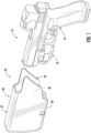
Figure 1 is a schematic perspective view of a holster including a tensioner in accordance with a first embodiment of the present invention, shown with a handgun outside of the chamber of the holster and out of engagement with the tensioner, with the handgun having a light mounted below the muzzle and the tensioner being mounted on the bottom wall of the holster body in a position to engage the light; -
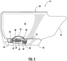
Figure 2 is an elevational view of the tensioner ofFigure 1 ; -
Figure 3 is a perspective view of the tensioner ofFigure 1 ; -
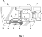
Figure 4 is an elevational view showing the handgun being inserted into the holster and the light coming into engagement with the tensioner; -
Figure 5 is a view similar toFigure 3 showing the handgun fully inserted into the holster and the tensioner fully engaged by the light; -
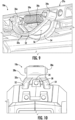
Figure 6 is a view of the tensioner as seen from the entranceway of the holster chamber; and -
Figures 7-10 illustrate a second embodiment of the invention, in which the tensioner is mounted on the top wall of the holster body; and -
Figure 11 illustrates a third embodiment of the invention, in which the tensioner is mounted on the bottom wall of the holster body in a position to engage the trigger guard of the handgun. -
Figures 1-6 illustrate ahandgun holster 10 that is a first embodiment of the invention. Theholster 10 is adapted to receive ahandgun assembly 12. Thehandgun assembly 12 includes ahandgun 14. Thehandgun assembly 12 that is illustrated herein also includes alight 16 that is mounted on the handgun below the handgun muzzle. Some handgun assemblies would not include a light mounted below the muzzle, but could include only the weapon itself. - The holster 10 (
Figure 1 ) includes aholster body 20 that defines achamber 22 for receiving thehandgun 14. Theholster 10 has an entranceway or opening 24 into thechamber 22 for allowing insertion of thehandgun 14 into the holster. Theholster body 20 has abottom wall 26 and atop wall 27. - It is desirable that the
handgun assembly 12 be positioned and retained in thechamber 22 in a way other than by a tight fit of the handgun itself in theholster 10. To that end, theholster 10 includes atensioner assembly 28 mounted on theholster body 20 in a position to be engaged by thehandgun assembly 12 when the handgun is inserted in thechamber 22. Thetensioner assembly 28 is operable, as described below, to apply a resilient biasing force to thehandgun assembly 12 when it is located in thechamber 22. In this first embodiment, thetensioner assembly 28 is mounted on thebottom wall 26 of theholster body 20 in a position to engage thelight 16. - The
tensioner assembly 28 in this embodiment includes two elements -- atensioner body 30, and atensioner spring 50. The tensioner body 30 (Figures 4-6 ) is a stiff but resilient element, in this case made from plastic, and is preferably formed as one piece, for example by molding. Thetensioner body 30 is mounted on thebottom wall 26 of theholster body 20 in a manner as described below. - The
tensioner body 30 has an elongate handgun engagement portion orcentral portion 32, extending between first andsecond end portions central portion 32 has a generally arcuate configuration, concave downward toward the outside (exterior) of theholster 10. Thecentral portion 32 has anouter side surface 38 that is presented toward theholster chamber 22, and an oppositeinner side surface 39. - The
first end portion 34 of thetensioner body 30 is formed as a hollow circular cylinder, from which afirst spring loop 40 extends toward thesecond end portion 36. Thesecond end portion 36 of thetensioner body 30 is formed as a transversely extending pin, from which asecond spring loop 42 extends toward thefirst end portion 34. - The holster
body bottom wall 26 includes acylindrical mounting boss 44 on which is supported thefirst end portion 34 of thetensioner body 30. Thefirst end portion 34 of thetensioner body 30 is closely fitted on theboss 44, and is rotatable on the boss without translational movement. - At the opposite end of the
tensioner body 30, the pin 41 on thesecond end portion 36 is fitted into aslot 46 in the holsterbody bottom wall 26. Theslot 46 extends longitudinally, that is, along the insertion and withdrawal direction of thehandgun 14. Thesecond end portion 36 of thetensioner body 30 is both (i) rotatable (pivotable) relative to theholster body 20, and (ii) slidable (translatable) along the length of theslot 46. These two degrees of freedom can be seen, for example, in a comparison ofFigures 4 and5 . - The
spring 50 extends in a force-transmitting relationship between the twoend portions tensioner body 30. Specifically, one end of thespring 50 is connected to thefirst spring loop 40, and the second end of the spring is connected to thesecond spring loop 42. Thespring 50 thus is located generally inside of and parallel to thecentral portion 32 of thetensioner body 30. In the illustrated embodiment, thespring 50 is a tension spring which resists elongation, that is, it resists movement of the two tensionerbody end portions spring 50 may be a compression spring, mounted outside thetensioner body 30. - The outer side surface 38 (
Figures 2 and3 ) of the tensioner bodycentral portion 32 is presented toward thechamber 22 of the holster body. Thecentral portion 32 of the tensioner body projects upward into thechamber 22 of theholster 10, through an opening in thebottom wall 26 of theholster body 20, as seen for example inFigure 6 . The location of thetensioner body 30 in theholster 10 is such thatouter side surface 38 of the tensioner bodycentral portion 32 is engageable by the handgun assembly 12 (in this case, the light 16) when the handgun assembly is located in thechamber 22. - When the
handgun assembly 12 is inserted into theholster 10, a lower surface on the handgun assembly engages theouter side surface 38 of the tensionercentral portion 32. In the illustrated embodiment, it is a surface on the light 16 that engages thetensioner body 30. In other embodiments, it may be another portion of thehandgun assembly 12, for example, the trigger guard of thehandgun 14. The arcuate tensionercentral portion 32 has a large radius to provide a smooth engagement with thehandgun assembly 12 during insertion and removal of thehandgun 14. - The force exerted on the
tensioner body 30 when thehandgun assembly 12 engages the tensionercentral portion 32 causes the central portion to be resiliently deformed downward and flatten out partially or completely, as can be seen from a comparison ofFigures 4 and5 . This flattening action occurs because the tensionerbody end portions spring 50. Specifically, the force exerted on thetensioner body 30 produces only rotational movement of the tensionerfirst end portion 34 on theholster body 20; while at the same time, it produces both sliding and rotational movement of the tensionersecond end portion 36 on the holster body, in a direction away from the first end portion. Thesecond end portion 36 slides away from thefirst end portion 34, enabling thecentral portion 32 to flatten. - The engagement between the
tensioner body 30 and thehandgun assembly 12 helps to position the handgun in theholster 10, and also helps to resist inadvertent movement of the handgun out of the holster. Because of the resilience of thetensioner body 30, thehandgun 14 does not have to be perfectly aligned with theholster 10 when the handgun is inserted into thechamber 22, in order for the full effect of thetensioner assembly 28 to be made available. Rather, the tensioner body can adjust and reposition itself so as to both position the handgun properly and help to secure it in the holster. - When the
handgun assembly 12 is thereafter removed from theholster 10, thespring 50 pulls thesecond end portion 36 of thetensioner body 30 back toward thefirst end portion 34. Thetensioner body 30 assumes its starting position again. - The range of motion of the
tensioner body 30, from compressed to extended, can be selected to accommodate handgun assemblies of different sizes and configurations. Thecentral portion 32 of thetensioner 30 can be more or less curved or flattened, depending on how far it is pressed by engagement with thehandgun assembly 12. As a result, thetensioner assembly 28 of the present invention adjusts automatically for whateverhandgun assembly 12 is inserted. In all embodiments, the amount of tension produced, can be selected to provide the desired amount of resistance to withdrawal of thehandgun 14 from theholster 10. - As noted above with respect to the prior art, a plastic tensioning member that is flexed and kept under tension for long periods of time will eventually relax and lose the residual stresses in the material under load, thus losing tension and allowing the weapon to rattle. In the present invention, the
spring 50 maintains this tension on thetensioner body 30 and does not permit it to relax under a continuous load, while also allowing it to flex to whatever position is necessary, depending on the size of the light attached, and still maintain and constant, positive pressure. -
Figures 7-10 illustrate ahandgun holster 10a that is a second embodiment of the invention. Theholster 10a is similar to theholster 10. Parts of theholster 10a that are the same or similar are given the same reference numeral with the suffix "a" added to distinguish them. - The
holster 10a includes adifferent tensioner assembly 28a, and thetensioner assembly 28a is mounted inside or otherwise on thetop wall 27a of the holster body. Thetensioner assembly 28a includes atensioner body 30a having acentral portion 32a that is split into twolegs gap 56 between them, to accommodate the passage of afront sight 58 of a handgun. - The
tensioner assembly 28a functions in a similar manner to thetensioner assembly 28. When the handgun is inserted, itsfront sight 58 passes between the two legs 33 of thetensioner body 30a. Thetensioner body 30a engages an upper portion of the handgun to position the handgun in theholster 10a and to resist inadvertent movement of the handgun out of the holster. - A
tensioner assembly 28 can be placed to engage the trigger guard of an insertedhandgun 12 rather than the light 16. This is illustrated inFig. 11 , with thetensioner assembly 28 being located farther rearward (to the right as viewed inFig. 11 ) on thebottom wall 26 of theholster body 20. - From the above description of the invention, those skilled in the art will perceive improvements, changes and modifications. Such improvements, changes and modifications within the skill of the art are intended to be covered by the appended claims.
Claims (10)
- A holster (10) for a handgun assembly (12), the holster (10) including:a holster body (20) having a chamber (22) for receiving the handgun assembly (12); anda tensioner (28) mounted on the holster body (20) in a position to be engaged by the handgun assembly (12) in the chamber (22), the tensioner (28) being operable to apply a resilient biasing force to the handgun assembly (12) in the chamber (22);the tensioner (28) including a tensioner body (30) that is engaged and deformed by the handgun assembly (12), and a spring (50) for resisting and controlling deformation of the tensioner body (30).
- A holster (10) as set forth in claim 1 wherein the tensioner body (30) has a resilient handgun engagement portion (32) extending between first and second end portions (34, 36), the tensioner first end portion (34) is mounted on the holster body (20) for only rotational movement on the holster body (20), and the tensioner second end portion (36) is mounted on the holster body (20) for both sliding and rotational movement on the holster body (20).
- A holster (10) as set forth in claim 2 wherein engagement of the handgun assembly (12) with the handgun engagement portion (32) of the tensioner body (30) causes the tensioner body second end portion (36) to slide away from the tensioner body first end portion (34), enabling the tensioner body central portion (32) to flatten.
- A holster (10) as set forth in claim 2 or 3 wherein the spring (50) is a tension spring (50) that extends between the first and second end portions (34, 36) of the tensioner body (30) and that maintains tension on the tensioner body (30) and does not allow the tensioner body (30) to relax under a continuous load.
- A holster (10) as set forth in any one of claims 2 to 4 wherein the handgun engagement portion (32) has a generally arcuate configuration that is concave downward toward the outside of the holster (10) and an outer side surface (38) that is presented toward the holster chamber (22) for engagement by the handgun assembly (12).
- A holster (10) as set forth in any preceding claim wherein the tensioner (28) is mounted on a bottom wall (26) of the holster body (20).
- A holster (10) as set forth in claim 6 wherein the tensioner (28) is mounted in a location on the bottom wall (26) to engage a light (16) that is carried by a handgun.
- A holster (10) as set forth in claim 6 or 7 wherein the tensioner (28) is mounted in a location on the bottom wall (26) to engage a trigger guard of a handgun.
- A holster (10) as set forth in any preceding claim wherein the tensioner (28) is mounted on a top wall (27) of the holster body (20).
- A holster (10) as set forth in any preceding claim wherein the tensioner body (30) has a resilient handgun engagement portion (32) extending between first and second end portions (34, 36), the tensioner first end portion (34) is mounted on the holster body (20) for only rotational movement on the holster body (20), and the tensioner second end portion (36) is mounted on the holster body (20) for both sliding and rotational movement on the holster body (20); whereinengagement of the handgun assembly (12) with the handgun engagement portion (32) of the tensioner body (30) causes the tensioner body second end portion (36) to slide away from the tensioner body first end portion (34), enabling the tensioner body central portion (32) to flatten; and whereinthe spring (50) is a tension spring (50) that extends between the first and second end portions (34, 36) of the tensioner body (30) and that maintains tension on the tensioner body (30) and does not allow the tensioner body (30) to relax under a continuous load.
Applications Claiming Priority (4)
| Application Number | Priority Date | Filing Date | Title |
|---|---|---|---|
| US202263320424P | 2022-03-16 | 2022-03-16 | |
| US202263354127P | 2022-06-21 | 2022-06-21 | |
| US202263357324P | 2022-06-30 | 2022-06-30 | |
| US18/104,901 US12078450B2 (en) | 2022-03-16 | 2023-02-02 | Holster tensioner device |
Publications (2)
| Publication Number | Publication Date |
|---|---|
| EP4246009A1 EP4246009A1 (en) | 2023-09-20 |
| EP4246009B1 true EP4246009B1 (en) | 2024-07-10 |
Family
ID=85601584
Family Applications (1)
| Application Number | Title | Priority Date | Filing Date |
|---|---|---|---|
| EP23161414.0A Active EP4246009B1 (en) | 2022-03-16 | 2023-03-13 | Holster tensioner device |
Country Status (5)
| Country | Link |
|---|---|
| US (2) | US12078450B2 (en) |
| EP (1) | EP4246009B1 (en) |
| AU (1) | AU2023201167B2 (en) |
| CA (1) | CA3193093C (en) |
| ES (1) | ES2991003T3 (en) |
Families Citing this family (7)
| Publication number | Priority date | Publication date | Assignee | Title |
|---|---|---|---|---|
| JP2022551382A (en) * | 2019-08-16 | 2022-12-09 | エッジ-ワークス・マニュファクチュアリング・カンパニー | firearm holster |
| USD1083363S1 (en) * | 2022-07-06 | 2025-07-15 | Safariland, Llc | Holster |
| US20240019227A1 (en) * | 2022-07-13 | 2024-01-18 | Safariland, Llc | Holster |
| US12416470B2 (en) * | 2023-10-25 | 2025-09-16 | Concealment Express, LLC | Holster with retention device and related methods |
| US20250237472A1 (en) * | 2024-01-18 | 2025-07-24 | Safariland, Llc | Holster |
| JP7607991B1 (en) | 2024-02-19 | 2025-01-06 | 有限会社佐野機工 | holster |
| USD1105741S1 (en) * | 2025-01-20 | 2025-12-16 | Bruce H. Griffin | Concealing holster |
Family Cites Families (13)
| Publication number | Priority date | Publication date | Assignee | Title |
|---|---|---|---|---|
| US2783536A (en) * | 1955-08-26 | 1957-03-05 | James M Boast | Knife and sheath with latch means |
| WO1997005443A1 (en) | 1995-07-26 | 1997-02-13 | Laser Products Corporation | Hand weapon holstering systems |
| US5944239A (en) * | 1997-08-11 | 1999-08-31 | Safariland Ltd., Inc. | Forward biased handgun holster with lock |
| CA2278999C (en) * | 1999-08-13 | 2001-03-20 | David Keefe | Release pull bar holster |
| CN2502231Y (en) | 2001-09-26 | 2002-07-24 | 陈信宏 | Anti-robbery holster |
| US7694860B2 (en) | 2005-01-20 | 2010-04-13 | Safariland Ltd, Inc. | Handgun locking device and holster |
| US8851344B2 (en) * | 2012-05-17 | 2014-10-07 | Gunhide Properties, Llc | Holster |
| US9194679B2 (en) * | 2013-03-15 | 2015-11-24 | Tactical Safety Systems, LLC | Magazine holder |
| US9322612B2 (en) | 2013-04-01 | 2016-04-26 | Safariland, Llc | Holster including trigger guard lock |
| EP3336479B1 (en) | 2016-12-14 | 2020-02-05 | Safariland, LLC | Holster tensioner device |
| US11346635B2 (en) | 2017-01-13 | 2022-05-31 | Surefire, Llc | Holster |
| US10712124B2 (en) * | 2017-08-11 | 2020-07-14 | Tulster, Llc | Retention clip |
| US20200232755A1 (en) | 2019-01-20 | 2020-07-23 | Vista Outdoor Operations Llc | Holster and holster spacer |
-
2023
- 2023-02-02 US US18/104,901 patent/US12078450B2/en active Active
- 2023-02-27 AU AU2023201167A patent/AU2023201167B2/en active Active
- 2023-03-13 ES ES23161414T patent/ES2991003T3/en active Active
- 2023-03-13 EP EP23161414.0A patent/EP4246009B1/en active Active
- 2023-03-15 CA CA3193093A patent/CA3193093C/en active Active
-
2024
- 2024-08-29 US US18/818,927 patent/US20250251214A1/en active Pending
Also Published As
| Publication number | Publication date |
|---|---|
| US20250251214A1 (en) | 2025-08-07 |
| CA3193093C (en) | 2025-10-14 |
| ES2991003T3 (en) | 2024-12-02 |
| US20230296350A1 (en) | 2023-09-21 |
| US12078450B2 (en) | 2024-09-03 |
| CA3193093A1 (en) | 2023-09-16 |
| AU2023201167B2 (en) | 2024-05-02 |
| AU2023201167A1 (en) | 2023-10-05 |
| EP4246009A1 (en) | 2023-09-20 |
Similar Documents
| Publication | Publication Date | Title |
|---|---|---|
| CA3193093C (en) | Holster tensioner device | |
| US7694860B2 (en) | Handgun locking device and holster | |
| US10317169B2 (en) | Holster tensioner device | |
| US5167355A (en) | Fast draw holster | |
| EP2307845B1 (en) | Retention holster | |
| US7841497B1 (en) | Holster retention system | |
| US8371487B1 (en) | Handgun holster | |
| US20070175935A1 (en) | Holster handgun locator and lock | |
| US5961013A (en) | Security Holster | |
| US20080121670A1 (en) | Weapon Holster System | |
| US4256243A (en) | Holster with hesitation lock | |
| US20120255979A1 (en) | Universal holder for a firearm | |
| US5150825A (en) | Holster with retention device | |
| US20220128332A1 (en) | Holster with Pushrod Ejection Port Locking Element | |
| US20200240744A1 (en) | Articulated Trigger Guard Blocking Device | |
| US20050188594A1 (en) | Shotgun forend sling adaptor and method of installation | |
| US12523444B2 (en) | Handgun holster with retention mechanism | |
| BR102023003607A2 (en) | HOLSTER FOR A FIREARM SET | |
| BR102023003607B1 (en) | HOLSTER FOR ONE SET OF FIREARM | |
| US9982964B1 (en) | Holster for a handgun | |
| ZA200905619B (en) | Holster |
Legal Events
| Date | Code | Title | Description |
|---|---|---|---|
| PUAI | Public reference made under article 153(3) epc to a published international application that has entered the european phase |
Free format text: ORIGINAL CODE: 0009012 |
|
| STAA | Information on the status of an ep patent application or granted ep patent |
Free format text: STATUS: THE APPLICATION HAS BEEN PUBLISHED |
|
| AK | Designated contracting states |
Kind code of ref document: A1 Designated state(s): AL AT BE BG CH CY CZ DE DK EE ES FI FR GB GR HR HU IE IS IT LI LT LU LV MC ME MK MT NL NO PL PT RO RS SE SI SK SM TR |
|
| STAA | Information on the status of an ep patent application or granted ep patent |
Free format text: STATUS: REQUEST FOR EXAMINATION WAS MADE |
|
| 17P | Request for examination filed |
Effective date: 20231013 |
|
| RBV | Designated contracting states (corrected) |
Designated state(s): AL AT BE BG CH CY CZ DE DK EE ES FI FR GB GR HR HU IE IS IT LI LT LU LV MC ME MK MT NL NO PL PT RO RS SE SI SK SM TR |
|
| GRAP | Despatch of communication of intention to grant a patent |
Free format text: ORIGINAL CODE: EPIDOSNIGR1 |
|
| STAA | Information on the status of an ep patent application or granted ep patent |
Free format text: STATUS: GRANT OF PATENT IS INTENDED |
|
| RIC1 | Information provided on ipc code assigned before grant |
Ipc: F41C 33/02 20060101ALI20240129BHEP Ipc: F16F 3/02 20060101AFI20240129BHEP |
|
| INTG | Intention to grant announced |
Effective date: 20240213 |
|
| P01 | Opt-out of the competence of the unified patent court (upc) registered |
Effective date: 20240412 |
|
| GRAS | Grant fee paid |
Free format text: ORIGINAL CODE: EPIDOSNIGR3 |
|
| GRAA | (expected) grant |
Free format text: ORIGINAL CODE: 0009210 |
|
| STAA | Information on the status of an ep patent application or granted ep patent |
Free format text: STATUS: THE PATENT HAS BEEN GRANTED |
|
| AK | Designated contracting states |
Kind code of ref document: B1 Designated state(s): AL AT BE BG CH CY CZ DE DK EE ES FI FR GB GR HR HU IE IS IT LI LT LU LV MC ME MK MT NL NO PL PT RO RS SE SI SK SM TR |
|
| REG | Reference to a national code |
Ref country code: CH Ref legal event code: EP |
|
| REG | Reference to a national code |
Ref country code: DE Ref legal event code: R096 Ref document number: 602023000214 Country of ref document: DE |
|
| REG | Reference to a national code |
Ref country code: NL Ref legal event code: FP |
|
| REG | Reference to a national code |
Ref country code: SE Ref legal event code: TRGR |
|
| REG | Reference to a national code |
Ref country code: LT Ref legal event code: MG9D |
|
| REG | Reference to a national code |
Ref country code: ES Ref legal event code: FG2A Ref document number: 2991003 Country of ref document: ES Kind code of ref document: T3 Effective date: 20241202 |
|
| PG25 | Lapsed in a contracting state [announced via postgrant information from national office to epo] |
Ref country code: PT Free format text: LAPSE BECAUSE OF FAILURE TO SUBMIT A TRANSLATION OF THE DESCRIPTION OR TO PAY THE FEE WITHIN THE PRESCRIBED TIME-LIMIT Effective date: 20241111 |
|
| REG | Reference to a national code |
Ref country code: AT Ref legal event code: MK05 Ref document number: 1702270 Country of ref document: AT Kind code of ref document: T Effective date: 20240710 |
|
| PG25 | Lapsed in a contracting state [announced via postgrant information from national office to epo] |
Ref country code: PT Free format text: LAPSE BECAUSE OF FAILURE TO SUBMIT A TRANSLATION OF THE DESCRIPTION OR TO PAY THE FEE WITHIN THE PRESCRIBED TIME-LIMIT Effective date: 20241111 |
|
| PG25 | Lapsed in a contracting state [announced via postgrant information from national office to epo] |
Ref country code: GR Free format text: LAPSE BECAUSE OF FAILURE TO SUBMIT A TRANSLATION OF THE DESCRIPTION OR TO PAY THE FEE WITHIN THE PRESCRIBED TIME-LIMIT Effective date: 20241011 Ref country code: FI Free format text: LAPSE BECAUSE OF FAILURE TO SUBMIT A TRANSLATION OF THE DESCRIPTION OR TO PAY THE FEE WITHIN THE PRESCRIBED TIME-LIMIT Effective date: 20240710 Ref country code: PL Free format text: LAPSE BECAUSE OF FAILURE TO SUBMIT A TRANSLATION OF THE DESCRIPTION OR TO PAY THE FEE WITHIN THE PRESCRIBED TIME-LIMIT Effective date: 20240710 |
|
| PG25 | Lapsed in a contracting state [announced via postgrant information from national office to epo] |
Ref country code: BG Free format text: LAPSE BECAUSE OF FAILURE TO SUBMIT A TRANSLATION OF THE DESCRIPTION OR TO PAY THE FEE WITHIN THE PRESCRIBED TIME-LIMIT Effective date: 20240710 |
|
| PG25 | Lapsed in a contracting state [announced via postgrant information from national office to epo] |
Ref country code: LV Free format text: LAPSE BECAUSE OF FAILURE TO SUBMIT A TRANSLATION OF THE DESCRIPTION OR TO PAY THE FEE WITHIN THE PRESCRIBED TIME-LIMIT Effective date: 20240710 |
|
| PG25 | Lapsed in a contracting state [announced via postgrant information from national office to epo] |
Ref country code: IS Free format text: LAPSE BECAUSE OF FAILURE TO SUBMIT A TRANSLATION OF THE DESCRIPTION OR TO PAY THE FEE WITHIN THE PRESCRIBED TIME-LIMIT Effective date: 20241110 Ref country code: AT Free format text: LAPSE BECAUSE OF FAILURE TO SUBMIT A TRANSLATION OF THE DESCRIPTION OR TO PAY THE FEE WITHIN THE PRESCRIBED TIME-LIMIT Effective date: 20240710 |
|
| PG25 | Lapsed in a contracting state [announced via postgrant information from national office to epo] |
Ref country code: HR Free format text: LAPSE BECAUSE OF FAILURE TO SUBMIT A TRANSLATION OF THE DESCRIPTION OR TO PAY THE FEE WITHIN THE PRESCRIBED TIME-LIMIT Effective date: 20240710 |
|
| PG25 | Lapsed in a contracting state [announced via postgrant information from national office to epo] |
Ref country code: RS Free format text: LAPSE BECAUSE OF FAILURE TO SUBMIT A TRANSLATION OF THE DESCRIPTION OR TO PAY THE FEE WITHIN THE PRESCRIBED TIME-LIMIT Effective date: 20241010 |
|
| PG25 | Lapsed in a contracting state [announced via postgrant information from national office to epo] |
Ref country code: RS Free format text: LAPSE BECAUSE OF FAILURE TO SUBMIT A TRANSLATION OF THE DESCRIPTION OR TO PAY THE FEE WITHIN THE PRESCRIBED TIME-LIMIT Effective date: 20241010 Ref country code: PL Free format text: LAPSE BECAUSE OF FAILURE TO SUBMIT A TRANSLATION OF THE DESCRIPTION OR TO PAY THE FEE WITHIN THE PRESCRIBED TIME-LIMIT Effective date: 20240710 Ref country code: LV Free format text: LAPSE BECAUSE OF FAILURE TO SUBMIT A TRANSLATION OF THE DESCRIPTION OR TO PAY THE FEE WITHIN THE PRESCRIBED TIME-LIMIT Effective date: 20240710 Ref country code: IS Free format text: LAPSE BECAUSE OF FAILURE TO SUBMIT A TRANSLATION OF THE DESCRIPTION OR TO PAY THE FEE WITHIN THE PRESCRIBED TIME-LIMIT Effective date: 20241110 Ref country code: HR Free format text: LAPSE BECAUSE OF FAILURE TO SUBMIT A TRANSLATION OF THE DESCRIPTION OR TO PAY THE FEE WITHIN THE PRESCRIBED TIME-LIMIT Effective date: 20240710 Ref country code: GR Free format text: LAPSE BECAUSE OF FAILURE TO SUBMIT A TRANSLATION OF THE DESCRIPTION OR TO PAY THE FEE WITHIN THE PRESCRIBED TIME-LIMIT Effective date: 20241011 Ref country code: FI Free format text: LAPSE BECAUSE OF FAILURE TO SUBMIT A TRANSLATION OF THE DESCRIPTION OR TO PAY THE FEE WITHIN THE PRESCRIBED TIME-LIMIT Effective date: 20240710 Ref country code: BG Free format text: LAPSE BECAUSE OF FAILURE TO SUBMIT A TRANSLATION OF THE DESCRIPTION OR TO PAY THE FEE WITHIN THE PRESCRIBED TIME-LIMIT Effective date: 20240710 Ref country code: AT Free format text: LAPSE BECAUSE OF FAILURE TO SUBMIT A TRANSLATION OF THE DESCRIPTION OR TO PAY THE FEE WITHIN THE PRESCRIBED TIME-LIMIT Effective date: 20240710 |
|
| REG | Reference to a national code |
Ref country code: DE Ref legal event code: R097 Ref document number: 602023000214 Country of ref document: DE |
|
| PG25 | Lapsed in a contracting state [announced via postgrant information from national office to epo] |
Ref country code: SM Free format text: LAPSE BECAUSE OF FAILURE TO SUBMIT A TRANSLATION OF THE DESCRIPTION OR TO PAY THE FEE WITHIN THE PRESCRIBED TIME-LIMIT Effective date: 20240710 Ref country code: RO Free format text: LAPSE BECAUSE OF FAILURE TO SUBMIT A TRANSLATION OF THE DESCRIPTION OR TO PAY THE FEE WITHIN THE PRESCRIBED TIME-LIMIT Effective date: 20240710 Ref country code: DK Free format text: LAPSE BECAUSE OF FAILURE TO SUBMIT A TRANSLATION OF THE DESCRIPTION OR TO PAY THE FEE WITHIN THE PRESCRIBED TIME-LIMIT Effective date: 20240710 |
|
| PG25 | Lapsed in a contracting state [announced via postgrant information from national office to epo] |
Ref country code: EE Free format text: LAPSE BECAUSE OF FAILURE TO SUBMIT A TRANSLATION OF THE DESCRIPTION OR TO PAY THE FEE WITHIN THE PRESCRIBED TIME-LIMIT Effective date: 20240710 |
|
| PG25 | Lapsed in a contracting state [announced via postgrant information from national office to epo] |
Ref country code: CZ Free format text: LAPSE BECAUSE OF FAILURE TO SUBMIT A TRANSLATION OF THE DESCRIPTION OR TO PAY THE FEE WITHIN THE PRESCRIBED TIME-LIMIT Effective date: 20240710 |
|
| PG25 | Lapsed in a contracting state [announced via postgrant information from national office to epo] |
Ref country code: SK Free format text: LAPSE BECAUSE OF FAILURE TO SUBMIT A TRANSLATION OF THE DESCRIPTION OR TO PAY THE FEE WITHIN THE PRESCRIBED TIME-LIMIT Effective date: 20240710 |
|
| PLBE | No opposition filed within time limit |
Free format text: ORIGINAL CODE: 0009261 |
|
| STAA | Information on the status of an ep patent application or granted ep patent |
Free format text: STATUS: NO OPPOSITION FILED WITHIN TIME LIMIT |
|
| 26N | No opposition filed |
Effective date: 20250411 |
|
| PG25 | Lapsed in a contracting state [announced via postgrant information from national office to epo] |
Ref country code: MC Free format text: LAPSE BECAUSE OF FAILURE TO SUBMIT A TRANSLATION OF THE DESCRIPTION OR TO PAY THE FEE WITHIN THE PRESCRIBED TIME-LIMIT Effective date: 20240710 |
|
| PG25 | Lapsed in a contracting state [announced via postgrant information from national office to epo] |
Ref country code: LU Free format text: LAPSE BECAUSE OF NON-PAYMENT OF DUE FEES Effective date: 20250313 |
|
| REG | Reference to a national code |
Ref country code: CH Ref legal event code: U11 Free format text: ST27 STATUS EVENT CODE: U-0-0-U10-U11 (AS PROVIDED BY THE NATIONAL OFFICE) Effective date: 20260401 |
|
| PGFP | Annual fee paid to national office [announced via postgrant information from national office to epo] |
Ref country code: SE Payment date: 20260327 Year of fee payment: 4 |
|
| PGFP | Annual fee paid to national office [announced via postgrant information from national office to epo] |
Ref country code: NO Payment date: 20260327 Year of fee payment: 4 Ref country code: IE Payment date: 20260327 Year of fee payment: 4 Ref country code: DE Payment date: 20260327 Year of fee payment: 4 |
|
| PGFP | Annual fee paid to national office [announced via postgrant information from national office to epo] |
Ref country code: BE Payment date: 20260327 Year of fee payment: 4 |
|
| PGFP | Annual fee paid to national office [announced via postgrant information from national office to epo] |
Ref country code: NL Payment date: 20260326 Year of fee payment: 4 |
|
| PGFP | Annual fee paid to national office [announced via postgrant information from national office to epo] |
Ref country code: FR Payment date: 20260325 Year of fee payment: 4 |
|
| PG25 | Lapsed in a contracting state [announced via postgrant information from national office to epo] |
Ref country code: CY Free format text: LAPSE BECAUSE OF FAILURE TO SUBMIT A TRANSLATION OF THE DESCRIPTION OR TO PAY THE FEE WITHIN THE PRESCRIBED TIME-LIMIT Effective date: 20240710 |
|
| PG25 | Lapsed in a contracting state [announced via postgrant information from national office to epo] |
Ref country code: LT Free format text: LAPSE BECAUSE OF FAILURE TO SUBMIT A TRANSLATION OF THE DESCRIPTION OR TO PAY THE FEE WITHIN THE PRESCRIBED TIME-LIMIT Effective date: 20240710 |
|
| PG25 | Lapsed in a contracting state [announced via postgrant information from national office to epo] |
Ref country code: TR Free format text: LAPSE BECAUSE OF FAILURE TO SUBMIT A TRANSLATION OF THE DESCRIPTION OR TO PAY THE FEE WITHIN THE PRESCRIBED TIME-LIMIT Effective date: 20240710 |
|
| PGFP | Annual fee paid to national office [announced via postgrant information from national office to epo] |
Ref country code: ES Payment date: 20260401 Year of fee payment: 4 |
|
| PGFP | Annual fee paid to national office [announced via postgrant information from national office to epo] |
Ref country code: IT Payment date: 20260331 Year of fee payment: 4 |
|
| PGFP | Annual fee paid to national office [announced via postgrant information from national office to epo] |
Ref country code: CH Payment date: 20260401 Year of fee payment: 4 |