EP4245981A1 - A driveline arrangement and a method of controlling a driveline arrangement - Google Patents
A driveline arrangement and a method of controlling a driveline arrangement Download PDFInfo
- Publication number
- EP4245981A1 EP4245981A1 EP22162151.9A EP22162151A EP4245981A1 EP 4245981 A1 EP4245981 A1 EP 4245981A1 EP 22162151 A EP22162151 A EP 22162151A EP 4245981 A1 EP4245981 A1 EP 4245981A1
- Authority
- EP
- European Patent Office
- Prior art keywords
- internal combustion
- combustion engine
- crank
- arrangement
- angle degree
- Prior art date
- Legal status (The legal status is an assumption and is not a legal conclusion. Google has not performed a legal analysis and makes no representation as to the accuracy of the status listed.)
- Granted
Links
Images


Classifications
-
- B—PERFORMING OPERATIONS; TRANSPORTING
- B63—SHIPS OR OTHER WATERBORNE VESSELS; RELATED EQUIPMENT
- B63H—MARINE PROPULSION OR STEERING
- B63H23/00—Transmitting power from propulsion power plant to propulsive elements
- B63H23/02—Transmitting power from propulsion power plant to propulsive elements with mechanical gearing
- B63H23/10—Transmitting power from propulsion power plant to propulsive elements with mechanical gearing for transmitting drive from more than one propulsion power unit
- B63H23/12—Transmitting power from propulsion power plant to propulsive elements with mechanical gearing for transmitting drive from more than one propulsion power unit allowing combined use of the propulsion power units
- B63H23/16—Transmitting power from propulsion power plant to propulsive elements with mechanical gearing for transmitting drive from more than one propulsion power unit allowing combined use of the propulsion power units characterised by provision of reverse drive
-
- F—MECHANICAL ENGINEERING; LIGHTING; HEATING; WEAPONS; BLASTING
- F02—COMBUSTION ENGINES; HOT-GAS OR COMBUSTION-PRODUCT ENGINE PLANTS
- F02D—CONTROLLING COMBUSTION ENGINES
- F02D25/00—Controlling two or more co-operating engines
- F02D25/02—Controlling two or more co-operating engines to synchronise speed
-
- B—PERFORMING OPERATIONS; TRANSPORTING
- B60—VEHICLES IN GENERAL
- B60K—ARRANGEMENT OR MOUNTING OF PROPULSION UNITS OR OF TRANSMISSIONS IN VEHICLES; ARRANGEMENT OR MOUNTING OF PLURAL DIVERSE PRIME-MOVERS IN VEHICLES; AUXILIARY DRIVES FOR VEHICLES; INSTRUMENTATION OR DASHBOARDS FOR VEHICLES; ARRANGEMENTS IN CONNECTION WITH COOLING, AIR INTAKE, GAS EXHAUST OR FUEL SUPPLY OF PROPULSION UNITS IN VEHICLES
- B60K5/00—Arrangement or mounting of internal-combustion or jet-propulsion units
- B60K5/08—Arrangement or mounting of internal-combustion or jet-propulsion units comprising more than one engine
-
- B—PERFORMING OPERATIONS; TRANSPORTING
- B63—SHIPS OR OTHER WATERBORNE VESSELS; RELATED EQUIPMENT
- B63H—MARINE PROPULSION OR STEERING
- B63H20/00—Outboard propulsion units, e.g. outboard motors or Z-drives; Arrangements thereof on vessels
- B63H20/14—Transmission between propulsion power unit and propulsion element
-
- B—PERFORMING OPERATIONS; TRANSPORTING
- B63—SHIPS OR OTHER WATERBORNE VESSELS; RELATED EQUIPMENT
- B63H—MARINE PROPULSION OR STEERING
- B63H23/00—Transmitting power from propulsion power plant to propulsive elements
- B63H23/02—Transmitting power from propulsion power plant to propulsive elements with mechanical gearing
- B63H23/10—Transmitting power from propulsion power plant to propulsive elements with mechanical gearing for transmitting drive from more than one propulsion power unit
- B63H23/12—Transmitting power from propulsion power plant to propulsive elements with mechanical gearing for transmitting drive from more than one propulsion power unit allowing combined use of the propulsion power units
-
- F—MECHANICAL ENGINEERING; LIGHTING; HEATING; WEAPONS; BLASTING
- F02—COMBUSTION ENGINES; HOT-GAS OR COMBUSTION-PRODUCT ENGINE PLANTS
- F02D—CONTROLLING COMBUSTION ENGINES
- F02D41/00—Electrical control of supply of combustible mixture or its constituents
- F02D41/009—Electrical control of supply of combustible mixture or its constituents using means for generating position or synchronisation signals
-
- F—MECHANICAL ENGINEERING; LIGHTING; HEATING; WEAPONS; BLASTING
- F02—COMBUSTION ENGINES; HOT-GAS OR COMBUSTION-PRODUCT ENGINE PLANTS
- F02D—CONTROLLING COMBUSTION ENGINES
- F02D41/00—Electrical control of supply of combustible mixture or its constituents
- F02D41/02—Circuit arrangements for generating control signals
- F02D41/021—Introducing corrections for particular conditions exterior to the engine
- F02D41/0215—Introducing corrections for particular conditions exterior to the engine in relation with elements of the transmission
- F02D41/022—Introducing corrections for particular conditions exterior to the engine in relation with elements of the transmission in relation with the clutch status
-
- F—MECHANICAL ENGINEERING; LIGHTING; HEATING; WEAPONS; BLASTING
- F02—COMBUSTION ENGINES; HOT-GAS OR COMBUSTION-PRODUCT ENGINE PLANTS
- F02D—CONTROLLING COMBUSTION ENGINES
- F02D2250/00—Engine control related to specific problems or objectives
- F02D2250/28—Control for reducing torsional vibrations, e.g. at acceleration
Definitions
- the present invention relates to a driveline arrangement.
- the invention also relates to a method of controlling a driveline arrangement.
- the invention will mainly be directed to a driveline arrangement for a marine vessel, the invention may also be applicable for other types of applications, such as for a driveline of a vehicle in the form of e.g. a truck, etc.
- the transmission arrangement is, for example, arranged to provide a number of gear ratios between the internal combustion engine and the drive unit, where the drive unit can be formed by e.g. the wheels of a vehicle or a propeller/impeller of a marine vessel.
- the transmission arrangement may also be configured to merely change between forward driving operation and rearward driving operation, which is conventional for a marine vessel implementation.
- a driveline arrangement comprising a first internal combustion engine comprising a first combustion cylinder housing a first reciprocating piston connected to a first crank shaft, wherein the first internal combustion engine is configured to assume a combustion stage in which a combustible gas is combusted in the first combustion cylinder, a second internal combustion engine comprising a second combustion cylinder housing a second reciprocating piston connected to a second crank shaft, wherein the second internal combustion engine is configured to assume a combustion stage in which a combustible gas is combusted in the second combustion cylinder, a transmission arrangement comprising a first input shaft drivingly connected to the first crank shaft, and a second input shaft drivingly connected to the second crank shaft, the transmission arrangement being configured to simultaneously receive a torque from the first and second crank shafts, wherein the transmission arrangement further comprises an output shaft connectable to a drive unit, and a control unit connected to the first and second internal combustion engines, the control unit comprising control circuitry configured to control the first internal combustion engine to
- the transmission arrangement of the present invention is thus configured to simultaneously receive torque from the first and the second internal combustion engine, i.e. receive torque from two internal combustion engines at the same time.
- the driveline arrangement hereby comprises two internal combustion engines for operating the driveline.
- the control unit may include a microprocessor, microcontroller, programmable digital signal processor or another programmable device.
- the control unit may also, or instead, include an application specific integrated circuit, a programmable gate array or programmable array logic, a programmable logic device, or a digital signal processor.
- the control unit includes a programmable device such as the microprocessor, microcontroller or programmable digital signal processor mentioned above, the processor may further include computer executable code that controls operation of the programmable device.
- the inventor has unexpectedly realised that rattle in free gears, i.e. gears of the transmission arrangement not being used for the transmission of torque, can be exposed to rattle, in particular for a transmission driven by two internal combustion engines.
- the present invention is based on the insight that the two internal combustion engines can be controlled in an efficient manner to reduce the rattle, and thereby reducing unwanted noise emitted from the driveline arrangement.
- the inventor has realised that by shifting the phasing of the internal combustion engines in such a way that the combustion stage of the respective internal combustion engine occurs at different point in time will reduce the torsional vibrations from the internal combustion engines into the transmission arrangement. Accordingly, the present invention enables, by relatively small efforts, to reduce the unwanted noise and wear of unloaded gears in a transmission arrangement operated by two internal combustion engines.
- control circuitry may be further configured to receive a signal from the first and second internal combustion engines, the signal being indicative of a crank angle degree of the first piston and the second piston, respectively, and adjust the crank angle degree of the first crank shaft based on a difference between the crank angle degree of the first piston and the crank angle degree of the second piston.
- the control circuitry is omitted from adjusting the crank angle degree of the first crank shaft.
- the control circuitry hereby keeps track of the combustion stages of each of the first and second internal combustion engines.
- the control circuitry may be configured to control the first internal combustion engine to assume its combustion stage in a range between 5 - 360 crank angle degrees compared to the combustion stage of the second internal combustion engine.
- the specific difference in crank angle degree may be dependent on the type of internal combustion engines, as well as the transmission arrangement in question.
- the control circuitry may be configured to control the first internal combustion engine to assume its combustion stage in a range between 20 - 300 crank angle degrees compared to the combustion stage of the second internal combustion engine.
- the first and second internal combustion engines are four stroke engines, i.e. they both operate with a 720 degrees crank angle rotation during a complete combustion cycle.
- control circuitry may be further configured to acquire data from a database, the data being indicative of a plurality of vibration levels of the transmission arrangement, wherein each of the vibration levels is associated with a respective crank angle degree of the first and second internal combustion engines, compare the plurality of vibration levels with each other, determine a crank angle degree difference between the first and second crank shafts representing a minimum vibration level of the transmission arrangement, and control the first internal combustion engine to adjust the crank angle degree of the first crank shaft to obtain the crank angle degree difference between the first and second crank shafts.
- control circuitry can receive test data which is indicative of an optimum difference in crank angle degree between the first and second crank shafts for reducing the noise caused by engine vibrations as much as possible.
- the driveline arrangement may further comprise a vibration sensor connected to the control unit, the control circuitry being further configured to receive a signal from the vibration sensor, the signal being indicative of a vibration level of the transmission arrangement, control the first internal combustion engine to adjust the crank angle degree of the first crank shaft to obtain the crank angle degree difference between the first and second crank shafts, receive an updated signal from the vibration sensor, the updated signal being indicative of a vibration level of the transmission arrangement after the crank angle degree has been adjusted, and compare the vibration level of the transmission arrangement after the crank angle degree is adjusted with the vibration level before the crank angle degree is adjusted to verify that the vibration level is reduced after the crank angle degree is adjusted.
- the vibration sensor may hereby continuously transmit the signal indicative of the vibration level of the transmission arrangement to the control circuitry.
- the control circuitry may, based on the received signal, iteratively adjust the crank angle degree of the first crank shaft until reaching a minimum vibration level.
- the driveline arrangement may further comprise a first overrunning clutch between the first crank shaft and the first input shaft.
- the control circuitry may be configured to control the first internal combustion engine to assume its combustion stage at the different point in time by controlling the overrunning clutch to assume a slipping state in which a relative rotation between the first crank shaft and the first input shaft is generated.
- the control circuitry can control the overrunning clutch to slip, whereby the point in time at which the combustion stage is performed for the first internal combustion engine will be adjusted.
- the control circuitry may be configured to control the first internal combustion engine to adjust the rotational speed of the first crank shaft when the overrunning clutch assumes the slipping state.
- the overrunning clutch is preferably also arranged to prevent the transmission arrangement to apply a torque on the first and second internal combustion engines, i.e. prevent that a torque is transmitted in the "wrong direction" from the transmission to the internal combustion engine.
- the transmission arrangement may be configured to switch between a forward driving mode and a rearward driving mode.
- the transmission arrangement is in this example embodiment thus only operable between the forward and rearward driving modes. Hence, when the transmission arrangement assumes the forward driving mode, the gears used during the rearward driving mode are unloaded and potentially exposed to rattle.
- the driveline arrangement may be a marine vessel driveline arrangement, and the drive unit is one of an impeller or a propeller.
- Rattle is preferably avoided for a marine vessel, in particular for a marine outboard motor, as the engine is located outside and can be perceived as disturbing when making too much noise.
- a marine inboard motor can also generate noise that can be perceived as disturbing, and it is thus preferable to reduce rattle also for this type of driveline arrangement.
- a method of controlling a driveline arrangement comprising a first internal combustion engine comprising a first combustion cylinder housing a first reciprocating piston connected to a first crank shaft, wherein the first internal combustion engine is configured to assume a combustion stage in which a combustible gas is combusted in the first combustion cylinder, a second internal combustion engine comprising a second combustion cylinder housing a second reciprocating piston connected to a second crank shaft, wherein the second internal combustion engine is configured to assume a combustion stage in which a combustible gas is combusted in the second combustion cylinder, and a transmission arrangement comprising a first input shaft drivingly connected to the first crank shaft, and a second input shaft drivingly connected to the second crank shaft, the transmission arrangement being configured to simultaneously receive a torque from the first and second crank shafts, wherein the transmission arrangement further comprises an output shaft operatively connected to a drive unit, wherein the method comprises the step of controlling the first internal combustion engine to assume its combustion stage at
- a marine vessel comprising a driveline arrangement according to any one of the embodiments described above in relation to the first aspect.
- a computer program comprising program code means for performing the step of the above described second aspect when the program is run on a computer.
- a computer readable medium carrying a computer program comprising program means for performing the step of the above described second aspect when the program means is run on a computer.
- a vehicle 1 in the form of a truck comprising a drive unit 150 in the form of propelled wheels.
- Fig. 1A indicates that the rear pair of wheels are arranged as propelled wheels, the present disclosure is of course applicable for propelling the front pair of wheels instead, or both the front and rear pair of wheels.
- the vehicle 1 comprises a driveline arrangement (illustrated in Fig. 2 ) for transmitting a torque to the drive unit 150.
- the driveline arrangement comprises a pair of internal combustion engines drivingly connected to a transmission arrangement, where the transmission arrangement comprises an output shaft connected to the drive unit.
- Fig. 1B is a perspective view of a marine vessel 2 which may be particularly suitable for incorporating the below described driveline arrangement.
- the marine vessel 2 comprises a drive unit 250 in the form of a propeller or impeller.
- Fig. 2 is a schematic illustration of the driveline arrangement according to an example embodiment.
- the embodiment in Fig. 2 is directed to the marine vessel 2 depicted in Fig. 1B but is also applicable for use by the vehicle 1 depicted in Fig. 1A .
- the driveline arrangement 100 comprises a first internal combustion engine 102 and a second internal combustion engine 202.
- the first internal combustion engine 102 comprises a first combustion cylinder 104.
- the first combustion cylinder 104 houses a first reciprocating piston 106 which is connected to a first crank shaft 108.
- the first reciprocating piston 106 is thus arranged to reciprocate between a bottom dead centre (BDC) and a top dead centre (TDC) within the first combustion cylinder 104.
- BDC bottom dead centre
- TDC top dead centre
- the first internal combustion engine 102 is configured to assume a combustion stage in which a combustible gas is combusted in the first combustion cylinder 104.
- the second internal combustion engine 202 comprises a second combustion cylinder 204.
- the second combustion cylinder 204 houses a second reciprocating piston 206 which is connected to a second crank shaft 208.
- the second reciprocating piston 206 is thus arranged to reciprocate between a bottom dead centre (BDC) and a top dead centre (TDC) within the second combustion cylinder 204.
- the second internal combustion engine 202 is configured to assume a combustion stage in which a combustible gas is combusted in the second combustion cylinder 204.
- each of the first 102 and second 202 internal combustion engines may be arranged as a respective hydrogen internal combustion engine (ICE).
- the combustion in such hydrogen ICE is based on a combustion of air and hydrogen.
- the hydrogen, or hydrogen fuel can be combusted in an internal combustion engine over a wide range of fuel-air mixtures.
- a hydrogen ICE may be operated to produce very low emissions during certain conditions.
- the hydrogen ICE may operate based on hydrogen liquid or hydrogen gas.
- each of the first 102 and second 202 internal combustion engines may be arranged as conventional diesel or petrol ICE, i.e. the combustible gas is provided by one of diesel and petrol. In the latter case, a spark plug (not shown) is used for combusting the petrol, while the compression of diesel fuel ignites combustible gas in the former case.
- first 102 and second 202 internal combustion engines may each be operated in a four stroke combustion cycle.
- the combustion stage for each of the first 102 and second 202 internal combustion engines occur once every 720 degree revolution of their respective crank shaft.
- the first 108 and second 208 crank shafts rotate 720 degrees between their combustion stages.
- the driveline arrangement 100 further comprises a transmission arrangement 300.
- the driveline depicted in Fig. 2 is configured to switch between a forward driving mode in which the marine vessel 2 operates in a forward driving direction, and a rearward driving mode in which the marine vessel 2 operates in a rearward driving direction.
- the transmission arrangement 300 comprises a first input shaft 302 which is drivingly connected to the first crank shaft 108.
- the first input shaft 302 receives a torque from the first crank shaft 108, which torque is generated by the first internal combustion engine 102.
- the transmission arrangement 300 also comprises a second input shaft 304 which is drivingly connected to the second crank shaft 208.
- the transmission arrangement 300 also receives a torque from the second internal combustion engine 202.
- the torque generated by the second internal combustion engine 202 is transmitted from the second crank shaft 208 to the second input shaft 304.
- the transmission arrangement 300 is configured to receive a torque from both the first 102 and the second 202 internal combustion engines.
- the transmission arrangement receives torque from the first 102 and second 202 internal combustion engines simultaneously and at the same time.
- the torque fed into the transmission arrangement 300 is transmitted to the drive unit 250 via an output shaft 306 of the transmission arrangement 300.
- the transmission can comprise gear wheel pairs in different configurations to provide desired gear rations in a known manner.
- the driveline arrangement 100 also comprises a first overrunning clutch 310.
- the first overrunning clutch 310 is arranged between the first crank shaft 108 and the first input shaft 302.
- the first overrunning clutch 310 is configured to prevent a torque from the transmission arrangement 300 in a direction from the first input shaft 302 to the first crank shaft 108.
- the first overrunning clutch 310 is also configured to assume a slipping state in which a relative rotation is generated between the first crank shaft 108 and the first input shaft 302.
- the first input shaft 302 rotates at a lower rotational speed compared to the rotational speed of the first crank shaft 108 when the first overrunning clutch assumes the slipping state.
- the driveline arrangement 100 also comprises a second overrunning clutch 320.
- the second overrunning clutch 320 is arranged between the second crank shaft 208 and the second input shaft 304.
- the second overrunning clutch 320 is configured to prevent a torque from the transmission arrangement 300 in a direction from the second input shaft 304 to the second crank shaft 208.
- the second overrunning clutch 320 is also configured to assume a slipping state in which a relative rotation is generated between the second crank shaft 208 and the second input shaft 304.
- the second input shaft 304 rotates at a lower rotational speed compared to the rotational speed of the second crank shaft 208 when the second overrunning clutch assumes the slipping state.
- the driveline arrangement 100 comprises a control unit 400 configured to control the operation of the first 102 and second 202 internal combustion engines.
- the driveline arrangement 100 also comprises a vibration sensor 402 arranged on the transmission arrangement 300, as well as a database 404 provided with vibration levels of the transmission arrangement 300 for a variety of mutual crank angle degrees of the first 102 and second 202 internal combustion engines, which will be described in further detail below.
- the transmission arrangement 300 is exposed to vibrations which may cause undesirable noise.
- the undesirable noise can be generated by rattle in unloaded gears of the transmission arrangement.
- the inventor of the present disclosure has realized that when the combustion stage of the first internal combustion engine 102 occurs at substantially the same point in time as the combustion stage of the second internal combustion engine 202, the vibration levels of the transmission arrangement tend to increase, which in turn generates noise at relatively high levels.
- the control unit 400 receives a signal from the first 102 and second 202 internal combustion engines.
- the signal is indicative of a point in time when the first internal combustion engine 102 assumes its combustion stage and a point in time when the second internal combustion engine 202 assumes its combustion stage, i.e. the control unit 400 hereby determines S0, as an optional initial stage, the relative position of the first 106 and second 206 pistons when the first internal combustion engine assumes its combustion stage. It is thus conceivable that the control unit 400 receives a first signal from the first internal combustion engine 102 and a second signal from the second internal combustion engine 202.
- the control unit 400 controls S1 the first internal combustion engine 102 to assume its combustion stage at a different point in time compared to the point in time at which the second internal combustion engine 202 assumes its combustion stage. This is executed by adjusting the crank angle degree of the first crank shaft 108. Preferably, the adjustment of the crank angle degree of the first crank shaft 108 is executed by controlling the first overrunning clutch 310 to assume the slipping state for a predetermined time period. The duration of the predetermined time period is dependent on a desired difference of the points in time when the first and second internal combustion engines assume their respective combustion stage.
- the slipping state of the first overrunning clutch 310 may also advantageously be combined with an adjustment of the rotational speed of the first crank shaft 108, which rotational speed is controlled by the control unit 400. Such adjustment is preferably executed by reducing the rotational speed of the first crank shaft 108.
- the control unit 400 is preferably connected to, or comprises, a database 404.
- the database 404 may be a cloud based database or implemented in software on a computer or the control unit 400.
- the database 400 may preferably contain data in the form of a plurality of vibration levels of the transmission arrangement 300. Each vibration level is associated with a respective crank angle degree of the first 102 and second 202 internal combustion engine. More particular, each vibration level is associated with a relative crank angle degree of the first 108 and second 208 crank shafts. The relative crank angle degree thus indicated different point in time when the first 102 and second 202 internal combustion engines assume their respective combustion stage.
- the control unit 400 is configured to compare the plurality of vibration levels with each other and determine a crank angle degree difference between the first 108 and second 208 crank shafts that represents a minimum vibration level of the transmission arrangement 300.
- the control unit 400 hereby control the first internal combustion engine 102 to adjust the crank angle degree of the first crank shaft 108 to obtain the crank angle degree difference that generates the minimum vibration level of the transmission arrangement 300.
- the exemplified driveline arrangement 300 comprises a vibration sensor 402 arranged on the transmission arrangement 300 and connected to the control unit 400.
- the vibration sensor 402 thus measures the vibration level of the transmission arrangement 300 during operation.
- control unit 400 can hereby receive a signal from the vibration sensor 402.
- the signal indicates a current vibration level of the transmission arrangement 300.
- the control unit 400 thereafter controls the first internal combustion engine 102 to adjust the crank angle degree of the first crank shaft 108.
- a crank angle degree difference between the first 108 and second 208 crank shafts is hereby obtained.
- the control unit 400 again, receives a signal indicative of an updated vibration level after the adjustment of the crank angle degree of the first crank shaft 108.
- the control unit 400 thereafter compares the vibration level of the transmission arrangement 300 after the crank angle degree is adjusted with the vibration level before the crank angle degree is adjusted.
- the control unit 400 can verify that the vibration level is reduced after the crank angle degree is adjusted. This process can proceed iteratively until a minimum vibration level is determined.
- the vibration sensor data and data from the database may be used in conjunction with each other or separate from each other.
- first 102 and second 202 internal combustion engines are, as described above, preferably operated in a four stroke cycle.
- the control unit thus preferably control the first internal combustion engine 102 to assume its combustion stage in a range between 5 - 360 crank angle degrees compared to the combustion stage of the second internal combustion engine 202.
Landscapes
- Engineering & Computer Science (AREA)
- Chemical & Material Sciences (AREA)
- Combustion & Propulsion (AREA)
- Mechanical Engineering (AREA)
- General Engineering & Computer Science (AREA)
- Ocean & Marine Engineering (AREA)
- Transportation (AREA)
- Output Control And Ontrol Of Special Type Engine (AREA)
- Transmission Devices (AREA)
Abstract
Description
- The present invention relates to a driveline arrangement. The invention also relates to a method of controlling a driveline arrangement. Although the invention will mainly be directed to a driveline arrangement for a marine vessel, the invention may also be applicable for other types of applications, such as for a driveline of a vehicle in the form of e.g. a truck, etc.
- Internal combustion engines and transmission arrangements are conventionally used in driveline arrangement for various types of vehicles, such as cars, trucks, marine vessels, and motorcycles. The transmission arrangement is, for example, arranged to provide a number of gear ratios between the internal combustion engine and the drive unit, where the drive unit can be formed by e.g. the wheels of a vehicle or a propeller/impeller of a marine vessel. The transmission arrangement may also be configured to merely change between forward driving operation and rearward driving operation, which is conventional for a marine vessel implementation.
- However, disturbing noise may be generated in the driveline during operation. In particular, unloaded gears, that is, gear wheel pairs may cause rattle in the transmission arrangement which cause both the unwanted noise as well as to some extent damage to the gears in terms of wear. The rattle is generated by the torsional vibrations generated by the internal combustion engine.
- It is therefore a desire to further improve driveline arrangements in terms of reducing noise caused by the torsional vibrations from the internal combustion engine.
- It is thus an object of the present invention to at least partially overcome the above described deficiencies.
- According to a first aspect, there is provided a driveline arrangement, comprising a first internal combustion engine comprising a first combustion cylinder housing a first reciprocating piston connected to a first crank shaft, wherein the first internal combustion engine is configured to assume a combustion stage in which a combustible gas is combusted in the first combustion cylinder, a second internal combustion engine comprising a second combustion cylinder housing a second reciprocating piston connected to a second crank shaft, wherein the second internal combustion engine is configured to assume a combustion stage in which a combustible gas is combusted in the second combustion cylinder, a transmission arrangement comprising a first input shaft drivingly connected to the first crank shaft, and a second input shaft drivingly connected to the second crank shaft, the transmission arrangement being configured to simultaneously receive a torque from the first and second crank shafts, wherein the transmission arrangement further comprises an output shaft connectable to a drive unit, and a control unit connected to the first and second internal combustion engines, the control unit comprising control circuitry configured to control the first internal combustion engine to assume its combustion stage at a different point in time compared to the point in time at which the second internal combustion engine assumes its combustion stage by adjusting a crank angle degree of the first crank shaft.
- The transmission arrangement of the present invention is thus configured to simultaneously receive torque from the first and the second internal combustion engine, i.e. receive torque from two internal combustion engines at the same time. The driveline arrangement hereby comprises two internal combustion engines for operating the driveline.
- The control unit may include a microprocessor, microcontroller, programmable digital signal processor or another programmable device. The control unit may also, or instead, include an application specific integrated circuit, a programmable gate array or programmable array logic, a programmable logic device, or a digital signal processor. Where the control unit includes a programmable device such as the microprocessor, microcontroller or programmable digital signal processor mentioned above, the processor may further include computer executable code that controls operation of the programmable device.
- The inventor has unexpectedly realised that rattle in free gears, i.e. gears of the transmission arrangement not being used for the transmission of torque, can be exposed to rattle, in particular for a transmission driven by two internal combustion engines. The present invention is based on the insight that the two internal combustion engines can be controlled in an efficient manner to reduce the rattle, and thereby reducing unwanted noise emitted from the driveline arrangement. In particular, the inventor has realised that by shifting the phasing of the internal combustion engines in such a way that the combustion stage of the respective internal combustion engine occurs at different point in time will reduce the torsional vibrations from the internal combustion engines into the transmission arrangement. Accordingly, the present invention enables, by relatively small efforts, to reduce the unwanted noise and wear of unloaded gears in a transmission arrangement operated by two internal combustion engines.
- According to an example embodiment, the control circuitry may be further configured to receive a signal from the first and second internal combustion engines, the signal being indicative of a crank angle degree of the first piston and the second piston, respectively, and adjust the crank angle degree of the first crank shaft based on a difference between the crank angle degree of the first piston and the crank angle degree of the second piston. Hence, should the combustion stage for the first internal combustion engine be performed at a different point in time compared to the combustion stage for the second internal combustion engine, the control circuitry is omitted from adjusting the crank angle degree of the first crank shaft. The control circuitry hereby keeps track of the combustion stages of each of the first and second internal combustion engines.
- According to an example embodiment, the control circuitry may be configured to control the first internal combustion engine to assume its combustion stage in a range between 5 - 360 crank angle degrees compared to the combustion stage of the second internal combustion engine. The specific difference in crank angle degree may be dependent on the type of internal combustion engines, as well as the transmission arrangement in question. According to an example, the control circuitry may be configured to control the first internal combustion engine to assume its combustion stage in a range between 20 - 300 crank angle degrees compared to the combustion stage of the second internal combustion engine. Preferably, the first and second internal combustion engines are four stroke engines, i.e. they both operate with a 720 degrees crank angle rotation during a complete combustion cycle.
- According to an example embodiment, the control circuitry may be further configured to acquire data from a database, the data being indicative of a plurality of vibration levels of the transmission arrangement, wherein each of the vibration levels is associated with a respective crank angle degree of the first and second internal combustion engines, compare the plurality of vibration levels with each other, determine a crank angle degree difference between the first and second crank shafts representing a minimum vibration level of the transmission arrangement, and control the first internal combustion engine to adjust the crank angle degree of the first crank shaft to obtain the crank angle degree difference between the first and second crank shafts.
- Hereby, the control circuitry can receive test data which is indicative of an optimum difference in crank angle degree between the first and second crank shafts for reducing the noise caused by engine vibrations as much as possible.
- According to an example embodiment, the driveline arrangement may further comprise a vibration sensor connected to the control unit, the control circuitry being further configured to receive a signal from the vibration sensor, the signal being indicative of a vibration level of the transmission arrangement, control the first internal combustion engine to adjust the crank angle degree of the first crank shaft to obtain the crank angle degree difference between the first and second crank shafts, receive an updated signal from the vibration sensor, the updated signal being indicative of a vibration level of the transmission arrangement after the crank angle degree has been adjusted, and compare the vibration level of the transmission arrangement after the crank angle degree is adjusted with the vibration level before the crank angle degree is adjusted to verify that the vibration level is reduced after the crank angle degree is adjusted.
- The vibration sensor may hereby continuously transmit the signal indicative of the vibration level of the transmission arrangement to the control circuitry. The control circuitry may, based on the received signal, iteratively adjust the crank angle degree of the first crank shaft until reaching a minimum vibration level.
- According to an example embodiment, the driveline arrangement may further comprise a first overrunning clutch between the first crank shaft and the first input shaft. According to an example embodiment, the control circuitry may be configured to control the first internal combustion engine to assume its combustion stage at the different point in time by controlling the overrunning clutch to assume a slipping state in which a relative rotation between the first crank shaft and the first input shaft is generated. Hereby, the control circuitry can control the overrunning clutch to slip, whereby the point in time at which the combustion stage is performed for the first internal combustion engine will be adjusted. According to an example embodiment, the control circuitry may be configured to control the first internal combustion engine to adjust the rotational speed of the first crank shaft when the overrunning clutch assumes the slipping state.
- The overrunning clutch is preferably also arranged to prevent the transmission arrangement to apply a torque on the first and second internal combustion engines, i.e. prevent that a torque is transmitted in the "wrong direction" from the transmission to the internal combustion engine.
- According to an example embodiment, the transmission arrangement may be configured to switch between a forward driving mode and a rearward driving mode. The transmission arrangement is in this example embodiment thus only operable between the forward and rearward driving modes. Hence, when the transmission arrangement assumes the forward driving mode, the gears used during the rearward driving mode are unloaded and potentially exposed to rattle.
- According to an example embodiment, the driveline arrangement may be a marine vessel driveline arrangement, and the drive unit is one of an impeller or a propeller. Rattle is preferably avoided for a marine vessel, in particular for a marine outboard motor, as the engine is located outside and can be perceived as disturbing when making too much noise. A marine inboard motor can also generate noise that can be perceived as disturbing, and it is thus preferable to reduce rattle also for this type of driveline arrangement.
- According to a second aspect, there is provided a method of controlling a driveline arrangement, the driveline arrangement comprising a first internal combustion engine comprising a first combustion cylinder housing a first reciprocating piston connected to a first crank shaft, wherein the first internal combustion engine is configured to assume a combustion stage in which a combustible gas is combusted in the first combustion cylinder, a second internal combustion engine comprising a second combustion cylinder housing a second reciprocating piston connected to a second crank shaft, wherein the second internal combustion engine is configured to assume a combustion stage in which a combustible gas is combusted in the second combustion cylinder, and a transmission arrangement comprising a first input shaft drivingly connected to the first crank shaft, and a second input shaft drivingly connected to the second crank shaft, the transmission arrangement being configured to simultaneously receive a torque from the first and second crank shafts, wherein the transmission arrangement further comprises an output shaft operatively connected to a drive unit, wherein the method comprises the step of controlling the first internal combustion engine to assume its combustion stage at a different point in time compared to the point in time at which the second internal combustion engine assumes its combustion stage by adjusting a crank angle degree of the first crank shaft.
- Effects and features of the second aspect are largely analogous to those described above in relation to the first aspect.
- According to a third aspect, there is provided a marine vessel comprising a driveline arrangement according to any one of the embodiments described above in relation to the first aspect.
- According to a fourth aspect, there is provided a computer program comprising program code means for performing the step of the above described second aspect when the program is run on a computer.
- According to a fifth aspect, there is provided a computer readable medium carrying a computer program comprising program means for performing the step of the above described second aspect when the program means is run on a computer.
- Effects and features of the third, fourth and fifth aspects are largely analogous to those described above in relation to the first aspect.
- Further features of, and advantages will become apparent when studying the appended claims and the following description. The skilled person will realize that different features may be combined to create embodiments other than those described in the following, without departing from the scope of the present disclosure.
- The above, as well as additional objects, features, and advantages, will be better understood through the following illustrative and non-limiting detailed description of exemplary embodiments, wherein:
-
Fig. 1A is a lateral side view illustrating an example embodiment of a vehicle in the form of a truck; -
Fig. 1B is a perspective view of a marine vessel according to an example embodiment, -
Fig. 2 is a schematic illustration of a driveline arrangement according to an example embodiment, and -
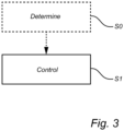
Fig. 3 is a flow chart of a method of controlling a driveline arrangement according to an example embodiment. - The present invention will now be described more fully hereinafter with reference to the accompanying drawings, in which exemplary embodiments are shown. The invention may, however, be embodied in many different forms and should not be construed as limited to the embodiments set forth herein; rather, these embodiments are provided for thoroughness and completeness. Like reference character refer to like elements throughout the description.
- With particular reference to
Fig. 1A , there is provided avehicle 1 in the form of a truck. Thevehicle 1 comprises adrive unit 150 in the form of propelled wheels. AlthoughFig. 1A indicates that the rear pair of wheels are arranged as propelled wheels, the present disclosure is of course applicable for propelling the front pair of wheels instead, or both the front and rear pair of wheels. Thevehicle 1 comprises a driveline arrangement (illustrated inFig. 2 ) for transmitting a torque to thedrive unit 150. As will be evident from the below disclosure in relation toFig. 2 , the driveline arrangement comprises a pair of internal combustion engines drivingly connected to a transmission arrangement, where the transmission arrangement comprises an output shaft connected to the drive unit. - Turning to
Fig. 1B , which is a perspective view of amarine vessel 2 which may be particularly suitable for incorporating the below described driveline arrangement. Themarine vessel 2 comprises adrive unit 250 in the form of a propeller or impeller. - In order to describe the
driveline arrangement 100 in further detail, reference is made toFig. 2 which is a schematic illustration of the driveline arrangement according to an example embodiment. The embodiment inFig. 2 is directed to themarine vessel 2 depicted inFig. 1B but is also applicable for use by thevehicle 1 depicted inFig. 1A . - As can be seen, the
driveline arrangement 100 comprises a firstinternal combustion engine 102 and a secondinternal combustion engine 202. The firstinternal combustion engine 102 comprises afirst combustion cylinder 104. Thefirst combustion cylinder 104 houses afirst reciprocating piston 106 which is connected to afirst crank shaft 108. Thefirst reciprocating piston 106 is thus arranged to reciprocate between a bottom dead centre (BDC) and a top dead centre (TDC) within thefirst combustion cylinder 104. Furthermore, the firstinternal combustion engine 102 is configured to assume a combustion stage in which a combustible gas is combusted in thefirst combustion cylinder 104. In a similar vein, the secondinternal combustion engine 202 comprises asecond combustion cylinder 204. Thesecond combustion cylinder 204 houses a second reciprocating piston 206 which is connected to asecond crank shaft 208. The second reciprocating piston 206 is thus arranged to reciprocate between a bottom dead centre (BDC) and a top dead centre (TDC) within thesecond combustion cylinder 204. Also, the secondinternal combustion engine 202 is configured to assume a combustion stage in which a combustible gas is combusted in thesecond combustion cylinder 204. - Furthermore, and as an example embodiment, each of the first 102 and second 202 internal combustion engines may be arranged as a respective hydrogen internal combustion engine (ICE). The combustion in such hydrogen ICE is based on a combustion of air and hydrogen. The hydrogen, or hydrogen fuel, can be combusted in an internal combustion engine over a wide range of fuel-air mixtures. A hydrogen ICE may be operated to produce very low emissions during certain conditions. The hydrogen ICE may operate based on hydrogen liquid or hydrogen gas. As another example, each of the first 102 and second 202 internal combustion engines may be arranged as conventional diesel or petrol ICE, i.e. the combustible gas is provided by one of diesel and petrol. In the latter case, a spark plug (not shown) is used for combusting the petrol, while the compression of diesel fuel ignites combustible gas in the former case.
- Moreover, the first 102 and second 202 internal combustion engines may each be operated in a four stroke combustion cycle. Hereby, the combustion stage for each of the first 102 and second 202 internal combustion engines occur once every 720 degree revolution of their respective crank shaft. In other words, the first 108 and second 208 crank shafts rotate 720 degrees between their combustion stages.
- As also depicted in
Fig. 2 , thedriveline arrangement 100 further comprises atransmission arrangement 300. The driveline depicted inFig. 2 is configured to switch between a forward driving mode in which themarine vessel 2 operates in a forward driving direction, and a rearward driving mode in which themarine vessel 2 operates in a rearward driving direction. Thetransmission arrangement 300 comprises afirst input shaft 302 which is drivingly connected to thefirst crank shaft 108. In further detail, thefirst input shaft 302 receives a torque from thefirst crank shaft 108, which torque is generated by the firstinternal combustion engine 102. Thetransmission arrangement 300 also comprises asecond input shaft 304 which is drivingly connected to thesecond crank shaft 208. Thus, thetransmission arrangement 300 also receives a torque from the secondinternal combustion engine 202. The torque generated by the secondinternal combustion engine 202 is transmitted from thesecond crank shaft 208 to thesecond input shaft 304. - Accordingly, the
transmission arrangement 300 is configured to receive a torque from both the first 102 and the second 202 internal combustion engines. In yet further detail, the transmission arrangement receives torque from the first 102 and second 202 internal combustion engines simultaneously and at the same time. The torque fed into thetransmission arrangement 300 is transmitted to thedrive unit 250 via anoutput shaft 306 of thetransmission arrangement 300. The transmission can comprise gear wheel pairs in different configurations to provide desired gear rations in a known manner. - Moreover, the
driveline arrangement 100 also comprises afirst overrunning clutch 310. Thefirst overrunning clutch 310 is arranged between thefirst crank shaft 108 and thefirst input shaft 302. Thefirst overrunning clutch 310 is configured to prevent a torque from thetransmission arrangement 300 in a direction from thefirst input shaft 302 to thefirst crank shaft 108. Thefirst overrunning clutch 310 is also configured to assume a slipping state in which a relative rotation is generated between thefirst crank shaft 108 and thefirst input shaft 302. Hence, thefirst input shaft 302 rotates at a lower rotational speed compared to the rotational speed of thefirst crank shaft 108 when the first overrunning clutch assumes the slipping state. - The
driveline arrangement 100 also comprises asecond overrunning clutch 320. Thesecond overrunning clutch 320 is arranged between thesecond crank shaft 208 and thesecond input shaft 304. Thesecond overrunning clutch 320 is configured to prevent a torque from thetransmission arrangement 300 in a direction from thesecond input shaft 304 to thesecond crank shaft 208. Thesecond overrunning clutch 320 is also configured to assume a slipping state in which a relative rotation is generated between thesecond crank shaft 208 and thesecond input shaft 304. Hence, thesecond input shaft 304 rotates at a lower rotational speed compared to the rotational speed of thesecond crank shaft 208 when the second overrunning clutch assumes the slipping state. - Still further, the
driveline arrangement 100 comprises acontrol unit 400 configured to control the operation of the first 102 and second 202 internal combustion engines. In the example embodiment, thedriveline arrangement 100 also comprises avibration sensor 402 arranged on thetransmission arrangement 300, as well as adatabase 404 provided with vibration levels of thetransmission arrangement 300 for a variety of mutual crank angle degrees of the first 102 and second 202 internal combustion engines, which will be described in further detail below. - During operation of the
driveline arrangement 100, thetransmission arrangement 300 is exposed to vibrations which may cause undesirable noise. The undesirable noise can be generated by rattle in unloaded gears of the transmission arrangement. The following description, with reference toFigs 2 and3 will now describe the underlying root cause of these increased vibrational levels and how to inventively reduce the vibrational levels to also reduce the noise. - The inventor of the present disclosure has realized that when the combustion stage of the first
internal combustion engine 102 occurs at substantially the same point in time as the combustion stage of the secondinternal combustion engine 202, the vibration levels of the transmission arrangement tend to increase, which in turn generates noise at relatively high levels. - During operation of the
driveline arrangement 100, thecontrol unit 400 receives a signal from the first 102 and second 202 internal combustion engines. The signal is indicative of a point in time when the firstinternal combustion engine 102 assumes its combustion stage and a point in time when the secondinternal combustion engine 202 assumes its combustion stage, i.e. thecontrol unit 400 hereby determines S0, as an optional initial stage, the relative position of the first 106 and second 206 pistons when the first internal combustion engine assumes its combustion stage. It is thus conceivable that thecontrol unit 400 receives a first signal from the firstinternal combustion engine 102 and a second signal from the secondinternal combustion engine 202. In the event the combustion stages for the first 102 and second 202 internal combustion engines occur at substantially the same time, thecontrol unit 400 controls S1 the firstinternal combustion engine 102 to assume its combustion stage at a different point in time compared to the point in time at which the secondinternal combustion engine 202 assumes its combustion stage. This is executed by adjusting the crank angle degree of thefirst crank shaft 108. Preferably, the adjustment of the crank angle degree of thefirst crank shaft 108 is executed by controlling the first overrunning clutch 310 to assume the slipping state for a predetermined time period. The duration of the predetermined time period is dependent on a desired difference of the points in time when the first and second internal combustion engines assume their respective combustion stage. The slipping state of thefirst overrunning clutch 310 may also advantageously be combined with an adjustment of the rotational speed of thefirst crank shaft 108, which rotational speed is controlled by thecontrol unit 400. Such adjustment is preferably executed by reducing the rotational speed of thefirst crank shaft 108. - As depicted in
Fig. 2 , thecontrol unit 400 is preferably connected to, or comprises, adatabase 404. Thedatabase 404 may be a cloud based database or implemented in software on a computer or thecontrol unit 400. Thedatabase 400 may preferably contain data in the form of a plurality of vibration levels of thetransmission arrangement 300. Each vibration level is associated with a respective crank angle degree of the first 102 and second 202 internal combustion engine. More particular, each vibration level is associated with a relative crank angle degree of the first 108 and second 208 crank shafts. The relative crank angle degree thus indicated different point in time when the first 102 and second 202 internal combustion engines assume their respective combustion stage. - The
control unit 400 is configured to compare the plurality of vibration levels with each other and determine a crank angle degree difference between the first 108 and second 208 crank shafts that represents a minimum vibration level of thetransmission arrangement 300. Thecontrol unit 400 hereby control the firstinternal combustion engine 102 to adjust the crank angle degree of thefirst crank shaft 108 to obtain the crank angle degree difference that generates the minimum vibration level of thetransmission arrangement 300. - As further depicted in
Fig. 2 , and as briefly indicated above, the exemplifieddriveline arrangement 300 comprises avibration sensor 402 arranged on thetransmission arrangement 300 and connected to thecontrol unit 400. Thevibration sensor 402 thus measures the vibration level of thetransmission arrangement 300 during operation. - During operation, the
control unit 400 can hereby receive a signal from thevibration sensor 402. The signal indicates a current vibration level of thetransmission arrangement 300. Thecontrol unit 400 thereafter controls the firstinternal combustion engine 102 to adjust the crank angle degree of thefirst crank shaft 108. - A crank angle degree difference between the first 108 and second 208 crank shafts is hereby obtained. The
control unit 400, again, receives a signal indicative of an updated vibration level after the adjustment of the crank angle degree of thefirst crank shaft 108. Thecontrol unit 400 thereafter compares the vibration level of thetransmission arrangement 300 after the crank angle degree is adjusted with the vibration level before the crank angle degree is adjusted. Hereby, thecontrol unit 400 can verify that the vibration level is reduced after the crank angle degree is adjusted. This process can proceed iteratively until a minimum vibration level is determined. - The vibration sensor data and data from the database may be used in conjunction with each other or separate from each other.
- Further, the first 102 and second 202 internal combustion engines are, as described above, preferably operated in a four stroke cycle. The control unit thus preferably control the first
internal combustion engine 102 to assume its combustion stage in a range between 5 - 360 crank angle degrees compared to the combustion stage of the secondinternal combustion engine 202. - It is to be understood that the present disclosure is not limited to the embodiments described above and illustrated in the drawings; rather, the skilled person will recognize that many changes and modifications may be made within the scope of the appended claims.
Claims (14)
- A driveline arrangement (100), comprising:- a first internal combustion engine (102) comprising a first combustion cylinder (104) housing a first reciprocating piston (106) connected to a first crank shaft (108), wherein the first internal combustion engine is configured to assume a combustion stage in which a combustible gas is combusted in the first combustion cylinder (104),- a second internal combustion engine (202) comprising a second combustion cylinder (204) housing a second reciprocating piston (206) connected to a second crank shaft (208), wherein the second internal combustion engine is configured to assume a combustion stage in which a combustible gas is combusted in the second combustion cylinder (204),- a transmission arrangement (300) comprising a first input shaft (302) drivingly connected to the first crank shaft (108), and a second input shaft (304) drivingly connected to the second crank shaft (208), the transmission arrangement (300) being configured to simultaneously receive a torque from the first (108) and second (208) crank shafts, wherein the transmission arrangement (300) further comprises an output shaft (306) connectable to a drive unit (150, 250), and- a control unit (400) connected to the first (102) and second (202) internal combustion engines, the control unit comprising control circuitry configured to control the first internal combustion engine (102) to assume its combustion stage at a different point in time compared to the point in time at which the second internal combustion engine (202) assumes its combustion stage by adjusting a crank angle degree of the first crank shaft (108).
- The driveline arrangement (100) according to claim 1, wherein the control circuitry is further configured to:- receive a signal from the first (102) and second (104) internal combustion engines, the signal being indicative of a crank angle degree of the first piston (106) and the second piston (206), respectively, and- adjust the crank angle degree of the first crank shaft (108) based on a difference between the crank angle degree of the first piston (106) and the crank angle degree of the second piston (206).
- The driveline arrangement (100) according to any one of claims 1 or 2, wherein the control circuitry is configured to control the first internal combustion engine (102) to assume its combustion stage in a range between 5 - 360 crank angle degrees compared to the combustion stage of the second internal combustion engine (202).
- The driveline arrangement (100) according to any one of the preceding claims, wherein the control circuitry is further configured to:- acquire data from a database (404), the data being indicative of a plurality of vibration levels of the transmission arrangement, wherein each of the vibration levels is associated with a respective crank angle degree of the first (102) and second (202) internal combustion engines,- compare the plurality of vibration levels with each other,- determine a crank angle degree difference between the first (108) and second (208) crank shafts representing a minimum vibration level of the transmission arrangement (100), and- control the first internal combustion engine (102) to adjust the crank angle degree of the first crank shaft (108) to obtain the crank angle degree difference between the first (108) and second (208) crank shafts.
- The driveline arrangement (100) according to any one of the preceding claims, wherein the driveline arrangement (100) further comprises a vibration sensor (402) connected to the control unit (400), the control circuitry being further configured to:- receive a signal from the vibration sensor (402), the signal being indicative of a vibration level of the transmission arrangement (300),- control the first internal combustion engine (102) to adjust the crank angle degree of the first crank shaft (108) to obtain the crank angle degree difference between the first (108) and second (208) crank shafts,- receive an updated signal from the vibration sensor, the updated signal being indicative of a vibration level of the transmission arrangement (300) after the crank angle degree has been adjusted, and- compare the vibration level of the transmission arrangement (300) after the crank angle degree is adjusted with the vibration level before the crank angle degree is adjusted to verify that the vibration level is reduced after the crank angle degree is adjusted.
- The driveline arrangement (100) according to any one of the preceding claims, further comprising a first overrunning clutch (310) between the first crank shaft (108) and the first input shaft (302).
- The driveline arrangement (100) according to claim 6, wherein the control circuitry is configured to control the first internal combustion engine (102) to assume its combustion stage at the different point in time by controlling the first overrunning clutch (310) to assume a slipping state in which a relative rotation between the first crank shaft (108) and the first input shaft (302) is generated.
- The driveline arrangement (100) according to claim 7, wherein the control circuitry is configured to control the first internal combustion engine (102) to adjust the rotational speed of the first crank shaft (108) when the first overrunning clutch (310) assumes the slipping state.
- The driveline arrangement (100) according to any one of the preceding claims, wherein the transmission arrangement (300) is configured to switch between a forward driving mode and a rearward driving mode.
- The driveline arrangement (100) according to any one of the preceding claims, wherein the driveline arrangement (100) is a marine vessel driveline arrangement, and the drive unit (250) is one of an impeller or a propeller.
- A method of controlling a driveline arrangement (100), the driveline arrangement comprising a first internal combustion engine (102) comprising a first combustion cylinder (104) housing a first reciprocating piston (106) connected to a first crank shaft (108), wherein the first internal combustion engine (102) is configured to assume a combustion stage in which a combustible gas is combusted in the first combustion cylinder (104), a second internal combustion engine (202) comprising a second combustion cylinder (204) housing a second reciprocating piston (206) connected to a second crank shaft (208), wherein the second internal combustion engine (202) is configured to assume a combustion stage in which a combustible gas is combusted in the second combustion cylinder (204), and a transmission arrangement (300) comprising a first input shaft (302) drivingly connected to the first crank shaft (108), and a second input shaft (304) drivingly connected to the second crank shaft (208), the transmission arrangement (300) being configured to simultaneously receive a torque from the first (108) and second (208) crank shafts, wherein the transmission arrangement (300) further comprises an output shaft (306) operatively connected to a drive unit (150, 250), wherein the method comprises the step of:- controlling the first internal combustion engine (102) to assume its combustion stage at a different point in time compared to the point in time at which the second internal combustion engine (202) assumes its combustion stage by adjusting a crank angle degree of the first crank shaft (108).
- A marine vessel (2) comprising a driveline arrangement (300) according to any one of claims 1 - 10.
- A computer program comprising program code means for performing the step of claim 11 when the program is run on a computer.
- A computer readable medium carrying a computer program comprising program means for performing the step of claim 11 when the program means is run on a computer.
Priority Applications (3)
| Application Number | Priority Date | Filing Date | Title |
|---|---|---|---|
| EP22162151.9A EP4245981B1 (en) | 2022-03-15 | 2022-03-15 | A driveline arrangement and a method of controlling a driveline arrangement |
| US18/114,354 US12103655B2 (en) | 2022-03-15 | 2023-02-27 | Driveline arrangement and method of controlling a driveline arrangement |
| CN202310227360.4A CN116767474A (en) | 2022-03-15 | 2023-03-10 | Powertrain device and method of controlling powertrain device |
Applications Claiming Priority (1)
| Application Number | Priority Date | Filing Date | Title |
|---|---|---|---|
| EP22162151.9A EP4245981B1 (en) | 2022-03-15 | 2022-03-15 | A driveline arrangement and a method of controlling a driveline arrangement |
Publications (2)
| Publication Number | Publication Date |
|---|---|
| EP4245981A1 true EP4245981A1 (en) | 2023-09-20 |
| EP4245981B1 EP4245981B1 (en) | 2025-06-25 |
Family
ID=80820286
Family Applications (1)
| Application Number | Title | Priority Date | Filing Date |
|---|---|---|---|
| EP22162151.9A Active EP4245981B1 (en) | 2022-03-15 | 2022-03-15 | A driveline arrangement and a method of controlling a driveline arrangement |
Country Status (3)
| Country | Link |
|---|---|
| US (1) | US12103655B2 (en) |
| EP (1) | EP4245981B1 (en) |
| CN (1) | CN116767474A (en) |
Citations (4)
| Publication number | Priority date | Publication date | Assignee | Title |
|---|---|---|---|---|
| DE516348C (en) * | 1929-09-28 | 1931-01-23 | Fried Krupp Germaniawerft Akt | Device for synchronizing two internal combustion engines, in particular marine propulsion engines |
| GB515353A (en) * | 1937-05-27 | 1939-12-04 | Deutsche Schiff & Maschb Ag | Apparatus for synchronising reciprocating engines |
| JPS57113935A (en) * | 1981-01-07 | 1982-07-15 | Hitachi Ltd | Phase control for multiple engine system |
| EP2067966A1 (en) * | 2007-12-06 | 2009-06-10 | Ford Global Technologies, LLC | Engine arrangement |
Family Cites Families (16)
| Publication number | Priority date | Publication date | Assignee | Title |
|---|---|---|---|---|
| JPH06104477B2 (en) * | 1986-06-18 | 1994-12-21 | 石川島播磨重工業株式会社 | Power transmission system with multiple engines |
| JP3306836B2 (en) * | 1993-05-31 | 2002-07-24 | ヤンマーディーゼル株式会社 | Engine coupling clutch structure |
| DE10244026A1 (en) | 2002-09-21 | 2004-04-01 | Zf Friedrichshafen Ag | Method and device for actively reducing clutch chatter in a motor vehicle |
| US6935115B2 (en) * | 2003-12-03 | 2005-08-30 | Daimlerchrysler Corporation | Controlling airflow to multiple engine modules with a single throttle body |
| JP4365431B2 (en) | 2007-08-10 | 2009-11-18 | トヨタ自動車株式会社 | Vehicle, drive device and control method thereof |
| US8393926B2 (en) * | 2009-02-12 | 2013-03-12 | Twin Disc, Inc. | Hybrid marine power train system |
| JP5501461B2 (en) * | 2010-06-15 | 2014-05-21 | 本田技研工業株式会社 | Vehicle drive system and method for controlling vehicle drive system |
| CN103189626B (en) * | 2010-11-02 | 2015-12-16 | 本田技研工业株式会社 | Drive system |
| US8631885B2 (en) * | 2010-12-17 | 2014-01-21 | Leo Oriet | Multi-use dual-engine, variable-power drive |
| US8936011B2 (en) * | 2011-03-04 | 2015-01-20 | Brb/Sherline, Inc. | Method for imposing variable load on the internal combustion engine used in vapor destruction applications |
| US8762022B1 (en) * | 2012-08-17 | 2014-06-24 | Brunswick Corporation | Marine propulsion system with efficient engine speed delta |
| JP2016203929A (en) * | 2015-04-28 | 2016-12-08 | 株式会社赤阪鉄工所 | Ship propulsion device |
| US10423756B2 (en) | 2016-10-28 | 2019-09-24 | Deere & Company | Gear phasing for noise control |
| JP2018108766A (en) * | 2016-12-28 | 2018-07-12 | ヤマハ発動機株式会社 | Outboard motor |
| SG11202008472YA (en) * | 2018-03-13 | 2020-10-29 | Ihi Power Systems Co Ltd | Power system for vessels |
| CN110481750A (en) * | 2019-08-19 | 2019-11-22 | 中国舰船研究设计中心 | Integral vibration-isolated ship single-shaft dual-engine propulsion system |
-
2022
- 2022-03-15 EP EP22162151.9A patent/EP4245981B1/en active Active
-
2023
- 2023-02-27 US US18/114,354 patent/US12103655B2/en active Active
- 2023-03-10 CN CN202310227360.4A patent/CN116767474A/en active Pending
Patent Citations (4)
| Publication number | Priority date | Publication date | Assignee | Title |
|---|---|---|---|---|
| DE516348C (en) * | 1929-09-28 | 1931-01-23 | Fried Krupp Germaniawerft Akt | Device for synchronizing two internal combustion engines, in particular marine propulsion engines |
| GB515353A (en) * | 1937-05-27 | 1939-12-04 | Deutsche Schiff & Maschb Ag | Apparatus for synchronising reciprocating engines |
| JPS57113935A (en) * | 1981-01-07 | 1982-07-15 | Hitachi Ltd | Phase control for multiple engine system |
| EP2067966A1 (en) * | 2007-12-06 | 2009-06-10 | Ford Global Technologies, LLC | Engine arrangement |
Also Published As
| Publication number | Publication date |
|---|---|
| EP4245981B1 (en) | 2025-06-25 |
| US20230294811A1 (en) | 2023-09-21 |
| US12103655B2 (en) | 2024-10-01 |
| CN116767474A (en) | 2023-09-19 |
Similar Documents
| Publication | Publication Date | Title |
|---|---|---|
| US8246517B2 (en) | Automatic stop/start controller for internal combustion engine | |
| US8041478B2 (en) | Securing and diagnosing the vehicle speed input and direction for torque control systems | |
| JP4552687B2 (en) | Misfire determination device and misfire determination method for internal combustion engine | |
| US10145329B2 (en) | Control system for internal combustion engine | |
| US20030144784A1 (en) | Control system for vehicle | |
| US6935115B2 (en) | Controlling airflow to multiple engine modules with a single throttle body | |
| US11241967B2 (en) | Motor vehicles, powertrain systems and control logic for the dynamic allocation of fast torque production | |
| CN116572934B (en) | Control device for hybrid vehicle | |
| US12103655B2 (en) | Driveline arrangement and method of controlling a driveline arrangement | |
| US6830532B1 (en) | Method for controlling a powertrain having multiple torque sources | |
| US20050023058A1 (en) | Method for providing acceleration in a multiple torque source powertrain to simulate a single torque source powertrain | |
| US11828246B2 (en) | Internal combustion engine system | |
| JP7694358B2 (en) | Hybrid vehicle control device | |
| US7162998B1 (en) | Method of starting an internal combustion engine for strong hybrid powertrains | |
| JPH1148831A (en) | Vehicle output control device | |
| US12497929B2 (en) | Hybrid vehicle | |
| JP2017137009A (en) | Hybrid vehicle | |
| CN116608070B (en) | Control device for hybrid vehicle | |
| JP2023070940A (en) | Hybrid vehicle control device | |
| JP2000343983A (en) | Vehicle drive control device | |
| JP2006161561A (en) | Fuel injection control device for internal combustion engine | |
| US20250122857A1 (en) | Start control device for internal combustion engine | |
| JP7729185B2 (en) | Hybrid vehicle control device | |
| JP2014202087A (en) | Ignition start control device for engine | |
| JP7218686B2 (en) | hybrid vehicle |
Legal Events
| Date | Code | Title | Description |
|---|---|---|---|
| PUAI | Public reference made under article 153(3) epc to a published international application that has entered the european phase |
Free format text: ORIGINAL CODE: 0009012 |
|
| STAA | Information on the status of an ep patent application or granted ep patent |
Free format text: STATUS: THE APPLICATION HAS BEEN PUBLISHED |
|
| AK | Designated contracting states |
Kind code of ref document: A1 Designated state(s): AL AT BE BG CH CY CZ DE DK EE ES FI FR GB GR HR HU IE IS IT LI LT LU LV MC MK MT NL NO PL PT RO RS SE SI SK SM TR |
|
| STAA | Information on the status of an ep patent application or granted ep patent |
Free format text: STATUS: REQUEST FOR EXAMINATION WAS MADE |
|
| 17P | Request for examination filed |
Effective date: 20240313 |
|
| RBV | Designated contracting states (corrected) |
Designated state(s): AL AT BE BG CH CY CZ DE DK EE ES FI FR GB GR HR HU IE IS IT LI LT LU LV MC MK MT NL NO PL PT RO RS SE SI SK SM TR |
|
| GRAP | Despatch of communication of intention to grant a patent |
Free format text: ORIGINAL CODE: EPIDOSNIGR1 |
|
| STAA | Information on the status of an ep patent application or granted ep patent |
Free format text: STATUS: GRANT OF PATENT IS INTENDED |
|
| INTG | Intention to grant announced |
Effective date: 20250220 |
|
| GRAS | Grant fee paid |
Free format text: ORIGINAL CODE: EPIDOSNIGR3 |
|
| GRAA | (expected) grant |
Free format text: ORIGINAL CODE: 0009210 |
|
| STAA | Information on the status of an ep patent application or granted ep patent |
Free format text: STATUS: THE PATENT HAS BEEN GRANTED |
|
| AK | Designated contracting states |
Kind code of ref document: B1 Designated state(s): AL AT BE BG CH CY CZ DE DK EE ES FI FR GB GR HR HU IE IS IT LI LT LU LV MC MK MT NL NO PL PT RO RS SE SI SK SM TR |
|
| REG | Reference to a national code |
Ref country code: GB Ref legal event code: FG4D |
|
| REG | Reference to a national code |
Ref country code: CH Ref legal event code: EP |
|
| REG | Reference to a national code |
Ref country code: CH Ref legal event code: EP |
|
| REG | Reference to a national code |
Ref country code: IE Ref legal event code: FG4D |
|
| REG | Reference to a national code |
Ref country code: DE Ref legal event code: R096 Ref document number: 602022016290 Country of ref document: DE |
|
| PG25 | Lapsed in a contracting state [announced via postgrant information from national office to epo] |
Ref country code: FI Free format text: LAPSE BECAUSE OF FAILURE TO SUBMIT A TRANSLATION OF THE DESCRIPTION OR TO PAY THE FEE WITHIN THE PRESCRIBED TIME-LIMIT Effective date: 20250625 |
|
| REG | Reference to a national code |
Ref country code: LT Ref legal event code: MG9D |
|
| PG25 | Lapsed in a contracting state [announced via postgrant information from national office to epo] |
Ref country code: NO Free format text: LAPSE BECAUSE OF FAILURE TO SUBMIT A TRANSLATION OF THE DESCRIPTION OR TO PAY THE FEE WITHIN THE PRESCRIBED TIME-LIMIT Effective date: 20250925 Ref country code: GR Free format text: LAPSE BECAUSE OF FAILURE TO SUBMIT A TRANSLATION OF THE DESCRIPTION OR TO PAY THE FEE WITHIN THE PRESCRIBED TIME-LIMIT Effective date: 20250926 |
|
| PG25 | Lapsed in a contracting state [announced via postgrant information from national office to epo] |
Ref country code: BG Free format text: LAPSE BECAUSE OF FAILURE TO SUBMIT A TRANSLATION OF THE DESCRIPTION OR TO PAY THE FEE WITHIN THE PRESCRIBED TIME-LIMIT Effective date: 20250625 |
|
| PG25 | Lapsed in a contracting state [announced via postgrant information from national office to epo] |
Ref country code: HR Free format text: LAPSE BECAUSE OF FAILURE TO SUBMIT A TRANSLATION OF THE DESCRIPTION OR TO PAY THE FEE WITHIN THE PRESCRIBED TIME-LIMIT Effective date: 20250625 |
|
| PG25 | Lapsed in a contracting state [announced via postgrant information from national office to epo] |
Ref country code: RS Free format text: LAPSE BECAUSE OF FAILURE TO SUBMIT A TRANSLATION OF THE DESCRIPTION OR TO PAY THE FEE WITHIN THE PRESCRIBED TIME-LIMIT Effective date: 20250925 |
|
| PG25 | Lapsed in a contracting state [announced via postgrant information from national office to epo] |
Ref country code: LV Free format text: LAPSE BECAUSE OF FAILURE TO SUBMIT A TRANSLATION OF THE DESCRIPTION OR TO PAY THE FEE WITHIN THE PRESCRIBED TIME-LIMIT Effective date: 20250625 |
|
| REG | Reference to a national code |
Ref country code: NL Ref legal event code: MP Effective date: 20250625 |
|
| PG25 | Lapsed in a contracting state [announced via postgrant information from national office to epo] |
Ref country code: NL Free format text: LAPSE BECAUSE OF FAILURE TO SUBMIT A TRANSLATION OF THE DESCRIPTION OR TO PAY THE FEE WITHIN THE PRESCRIBED TIME-LIMIT Effective date: 20250625 |
|
| PG25 | Lapsed in a contracting state [announced via postgrant information from national office to epo] |
Ref country code: PT Free format text: LAPSE BECAUSE OF FAILURE TO SUBMIT A TRANSLATION OF THE DESCRIPTION OR TO PAY THE FEE WITHIN THE PRESCRIBED TIME-LIMIT Effective date: 20251027 |
|
| REG | Reference to a national code |
Ref country code: AT Ref legal event code: MK05 Ref document number: 1806654 Country of ref document: AT Kind code of ref document: T Effective date: 20250625 |
|
| PG25 | Lapsed in a contracting state [announced via postgrant information from national office to epo] |
Ref country code: IS Free format text: LAPSE BECAUSE OF FAILURE TO SUBMIT A TRANSLATION OF THE DESCRIPTION OR TO PAY THE FEE WITHIN THE PRESCRIBED TIME-LIMIT Effective date: 20251025 |
|
| PG25 | Lapsed in a contracting state [announced via postgrant information from national office to epo] |
Ref country code: AT Free format text: LAPSE BECAUSE OF FAILURE TO SUBMIT A TRANSLATION OF THE DESCRIPTION OR TO PAY THE FEE WITHIN THE PRESCRIBED TIME-LIMIT Effective date: 20250625 Ref country code: SM Free format text: LAPSE BECAUSE OF FAILURE TO SUBMIT A TRANSLATION OF THE DESCRIPTION OR TO PAY THE FEE WITHIN THE PRESCRIBED TIME-LIMIT Effective date: 20250625 |
|
| PG25 | Lapsed in a contracting state [announced via postgrant information from national office to epo] |
Ref country code: CZ Free format text: LAPSE BECAUSE OF FAILURE TO SUBMIT A TRANSLATION OF THE DESCRIPTION OR TO PAY THE FEE WITHIN THE PRESCRIBED TIME-LIMIT Effective date: 20250625 |
|
| PG25 | Lapsed in a contracting state [announced via postgrant information from national office to epo] |
Ref country code: PL Free format text: LAPSE BECAUSE OF FAILURE TO SUBMIT A TRANSLATION OF THE DESCRIPTION OR TO PAY THE FEE WITHIN THE PRESCRIBED TIME-LIMIT Effective date: 20250625 |
|
| PG25 | Lapsed in a contracting state [announced via postgrant information from national office to epo] |
Ref country code: EE Free format text: LAPSE BECAUSE OF FAILURE TO SUBMIT A TRANSLATION OF THE DESCRIPTION OR TO PAY THE FEE WITHIN THE PRESCRIBED TIME-LIMIT Effective date: 20250625 |
|
| PG25 | Lapsed in a contracting state [announced via postgrant information from national office to epo] |
Ref country code: SK Free format text: LAPSE BECAUSE OF FAILURE TO SUBMIT A TRANSLATION OF THE DESCRIPTION OR TO PAY THE FEE WITHIN THE PRESCRIBED TIME-LIMIT Effective date: 20250625 |
|
| PG25 | Lapsed in a contracting state [announced via postgrant information from national office to epo] |
Ref country code: ES Free format text: LAPSE BECAUSE OF FAILURE TO SUBMIT A TRANSLATION OF THE DESCRIPTION OR TO PAY THE FEE WITHIN THE PRESCRIBED TIME-LIMIT Effective date: 20250625 |
|
| REG | Reference to a national code |
Ref country code: DE Ref legal event code: R097 Ref document number: 602022016290 Country of ref document: DE |
|
| PG25 | Lapsed in a contracting state [announced via postgrant information from national office to epo] |
Ref country code: DK Free format text: LAPSE BECAUSE OF FAILURE TO SUBMIT A TRANSLATION OF THE DESCRIPTION OR TO PAY THE FEE WITHIN THE PRESCRIBED TIME-LIMIT Effective date: 20250625 |
|
| PGFP | Annual fee paid to national office [announced via postgrant information from national office to epo] |
Ref country code: DE Payment date: 20260320 Year of fee payment: 5 |
|
| PGFP | Annual fee paid to national office [announced via postgrant information from national office to epo] |
Ref country code: IT Payment date: 20260320 Year of fee payment: 5 |
|
| PLBE | No opposition filed within time limit |
Free format text: ORIGINAL CODE: 0009261 |
|
| STAA | Information on the status of an ep patent application or granted ep patent |
Free format text: STATUS: NO OPPOSITION FILED WITHIN TIME LIMIT |
|
| REG | Reference to a national code |
Ref country code: CH Ref legal event code: L10 Free format text: ST27 STATUS EVENT CODE: U-0-0-L10-L00 (AS PROVIDED BY THE NATIONAL OFFICE) Effective date: 20260507 |
|
| 26N | No opposition filed |
Effective date: 20260326 |
|
| PG25 | Lapsed in a contracting state [announced via postgrant information from national office to epo] |
Ref country code: LT Free format text: LAPSE BECAUSE OF FAILURE TO SUBMIT A TRANSLATION OF THE DESCRIPTION OR TO PAY THE FEE WITHIN THE PRESCRIBED TIME-LIMIT Effective date: 20250625 |
|
| PG25 | Lapsed in a contracting state [announced via postgrant information from national office to epo] |
Ref country code: SE Free format text: LAPSE BECAUSE OF FAILURE TO SUBMIT A TRANSLATION OF THE DESCRIPTION OR TO PAY THE FEE WITHIN THE PRESCRIBED TIME-LIMIT Effective date: 20250625 |