EP4245926A1 - Attachment module, excavator arm, excavator, and method of rotating a tool relative to excavator arm - Google Patents
Attachment module, excavator arm, excavator, and method of rotating a tool relative to excavator arm Download PDFInfo
- Publication number
- EP4245926A1 EP4245926A1 EP23161533.7A EP23161533A EP4245926A1 EP 4245926 A1 EP4245926 A1 EP 4245926A1 EP 23161533 A EP23161533 A EP 23161533A EP 4245926 A1 EP4245926 A1 EP 4245926A1
- Authority
- EP
- European Patent Office
- Prior art keywords
- section
- tool
- arm
- excavator
- attachment module
- Prior art date
- Legal status (The legal status is an assumption and is not a legal conclusion. Google has not performed a legal analysis and makes no representation as to the accuracy of the status listed.)
- Granted
Links
Images



Classifications
-
- E—FIXED CONSTRUCTIONS
- E02—HYDRAULIC ENGINEERING; FOUNDATIONS; SOIL SHIFTING
- E02F—DREDGING; SOIL-SHIFTING
- E02F3/00—Dredgers; Soil-shifting machines
- E02F3/04—Dredgers; Soil-shifting machines mechanically-driven
- E02F3/28—Dredgers; Soil-shifting machines mechanically-driven with digging tools mounted on a dipper- or bucket-arm, i.e. there is either one arm or a pair of arms, e.g. dippers, buckets
- E02F3/36—Component parts
- E02F3/3604—Devices to connect tools to arms, booms or the like
- E02F3/3677—Devices to connect tools to arms, booms or the like allowing movement, e.g. rotation or translation, of the tool around or along another axis as the movement implied by the boom or arms, e.g. for tilting buckets
- E02F3/3681—Rotators
-
- E—FIXED CONSTRUCTIONS
- E02—HYDRAULIC ENGINEERING; FOUNDATIONS; SOIL SHIFTING
- E02F—DREDGING; SOIL-SHIFTING
- E02F3/00—Dredgers; Soil-shifting machines
- E02F3/04—Dredgers; Soil-shifting machines mechanically-driven
- E02F3/18—Dredgers; Soil-shifting machines mechanically-driven with digging wheels turning round an axis, e.g. bucket-type wheels
- E02F3/22—Component parts
- E02F3/26—Safety or control devices
-
- E—FIXED CONSTRUCTIONS
- E02—HYDRAULIC ENGINEERING; FOUNDATIONS; SOIL SHIFTING
- E02F—DREDGING; SOIL-SHIFTING
- E02F9/00—Component parts of dredgers or soil-shifting machines, not restricted to one of the kinds covered by groups E02F3/00 - E02F7/00
- E02F9/20—Drives; Control devices
- E02F9/22—Hydraulic or pneumatic drives
Definitions
- the present disclosure relates to an attachment module configured to attach a tool to a distal end of an excavator arm.
- the present disclosure further relates to an excavator arm, an excavator comprising an excavator arm, a method of rotating a tool relative to an excavator arm of an excavator, a computer program, and a computer-readable medium.
- Excavators and backhoes are examples of excavator machines which use an excavator arm and a tool, such as a bucket, attached to a distal end of the excavator arm to perform various tasks such as digging, levelling, performing forestry work, demolition, and the like.
- An excavator is usually a heavy construction equipment comprising a cab for an operator on a rotating platform known as an upper structure.
- the upper structure can be arranged on an undercarriage with tracks or wheels.
- a backhoe also called rear actor or back actor, is a type of excavating equipment typically mounted on the back of a tractor or front loader.
- the excavator arm of an excavator machine is normally powered by a number of hydraulic cylinders such that the distal end of the excavator arm can be moved to perform a task with a tool attached to the distal end of the excavator arm.
- the excavator arm normally comprises a tool attachment section for a tool at a distal portion of the excavator arm to which a tool, such as a bucket can be arranged.
- An excavator arm typically comprises a so-called boom which is an arm section closest to the vehicle, and a so-called stick which is attached to the boom.
- the tool attachment section is usually attached to the stick.
- Excavator machines such as excavators and backhoes, come in various sizes and prize ranges.
- Most excavator machines can be provided with an excavator arm capable of rotating the tool attachment section through 360 degrees relative to the stick using a hydraulic motor.
- a more versatile excavator arm is provided because the angle of the operation direction of the tool can be varied which can increase the flexibility and the precision of the operation of the tool.
- such a function can add costs, complexity, and weight to the excavator arm and thereby also to the excavator machine comprising the excavator arm.
- modules are available on the market which comprise a hydraulic motor allowing rotation of a tool section of an excavator arm and which can be mounted to existing excavator arms which lacks the above-mentioned rotator function.
- Such modules are commonly referred to as a tiltrotator and are also known under a number of trade names.
- These types of modules can provide a more versatile excavator arm because they allow variation of the angle of the operation direction of the tool which can increase the flexibility and the precision of the operation of the tool.
- these modules may be costly and complex to manufacture and for many users, these modules may be considered to be too expensive, especially in cases where it is intended to be used on a smaller type of excavator machine.
- the weight and size of the above-mentioned type of module may not be suited for use on a smaller type of excavator machine.
- an attachment module configured to attach a tool to a distal end of an excavator arm.
- the attachment module comprises an arm section comprising a first attachment arrangement for attaching the arm section to the distal end of the excavator arm, and a tool section comprising a second attachment arrangement for attaching the tool to the tool section.
- the tool section is rotatably arranged relative to the arm section around a rotation axis.
- the attachment module comprises a locking assembly controllable between a locked state in which the locking assembly locks the tool section from rotating relative to the arm section around the rotation axis, and an unlocked state in which the locking assembly unlocks the tool section from the arm section such that the tool section is free to rotate relative to the arm section around the rotation axis.
- an attachment module is provided allowing a change in the operation direction of a tool attached to the tool section relative to a distal end of an excavator arm in a manner circumventing the need for a hydraulic motor for rotating the tool section.
- a user may rotate the tool section relative to the arm section, and thus also a tool relative to a distal end of an excavator arm, by controlling the locking assembly to the unlocked state and applying an external force or torque onto the tool section, or to a tool attached to the tool section. Since the tool section is free to rotate relative to the arm section around the rotation axis when the locking assembly is in the unlocked state, such an external force or torque can rotate the tool section relative to the distal end of the excavator arm.
- the external force or torque may be applied to the tool section, or to a tool attached to the tool section, by controlling the excavator arm such that the tool or tool section abuts against an external surface and controlling the excavator arm such that the arm section of the attachment module is moved relative to the external surface.
- the user may control the locking assembly to the locked state to lock the tool section from further rotating relative to the arm section.
- the attachment module allows a change in the operation direction of a tool attached to the tool section relative to a distal end of an excavator arm in a manner circumventing the need for a hydraulic motor for rotating the tool section, a simple and efficient attachment module is provided having conditions for improving flexibility and precision of the operation of an excavator machine while having conditions and characteristics suitable for being manufactured and assembled in a cost-efficient manner.
- an attachment module is provided capable of allowing a change in the operation direction of a tool attached to the tool section, while having conditions for being compact and having conditions for having a low weight. Therefore, the attachment module according to the embodiments herein can be made suitable for use on smaller types of excavator machines as well as for use on larger or mid-sized excavator machines.
- an attachment module is provided overcoming, or at least alleviating, at least some of the above-mentioned problems and drawbacks. As a result, the above-mentioned object is achieved.
- the attachment module comprises an input unit connectable to the locking assembly for controlling the locking assembly between the locked and unlocked states based on input from the input unit.
- the input unit can be arranged in an operator area of an excavator machine, such as a cab or other type of operator area of the excavator machine, and can be connected to the locking assembly of the attachment module. In this manner, a user is allowed to change the operation direction of a tool attached to the tool section relative to a distal end of an excavator arm without having to leave the operator area of the excavator machine.
- the second attachment arrangement is configured to attach the tool to the tool section to allow the tool to operate in a main operation direction by a movement of the excavator arm in the main operation direction, and wherein the rotation axis is substantially perpendicular to the main operation direction of the tool.
- an attachment module is provided having conditions for even further improving the flexibility and the precision of the operation of an excavator machine while having conditions and characteristics suitable for being manufactured and assembled in a cost-efficient manner.
- the tool section is free to rotate more than 360 degrees relative to the arm section around the rotation axis when the locking assembly is in the unlocked state.
- an attachment module is provided allowing a full rotation of a tool relative to a distal end of an excavator arm thereby further improving flexibility and precision of the operation of an excavator machine while having conditions and characteristics suitable for being manufactured and assembled in a cost-efficient manner.
- the locking assembly comprises a locking member and an actuator assembly operably connected to the locking member to move the locking member between a locking position, in which the locking assembly assumes the locked state, and an unlocking position, in which the locking assembly assumes the unlocked state.
- the locking assembly further comprises a first toothed section arranged on the arm section, a second toothed section arranged on the tool section, and a third toothed section arranged on the locking member, and wherein the third toothed section engages with both of the first and second toothed sections when the locking member is in the locking position and engages with only one of the first and second toothed sections when the locking member is in the unlocking position.
- a locking assembly is provided having conditions for being simple, robust, and durable.
- an attachment module is provided having conditions for having a low weight and being compact.
- the third toothed section engages with the second toothed section when the locking member is in the unlocking position.
- each of the first, second and third toothed sections circumscribes the rotation axis.
- a locking assembly is provided having conditions for being simple, compact, robust, and durable.
- each of the first and second toothed sections comprises internal teeth and wherein the third toothed section comprises external teeth.
- the third toothed section comprises external teeth.
- the rotation axis extends through the actuator assembly.
- the locking member is movable in directions parallel to the rotation axis between the locking and unlocking positions.
- the actuator assembly comprises an actuator configured to move the locking member to one of the locking and unlocking positions when activated, and wherein the actuator assembly comprises at least one spring element configured to bias the locking member towards the other of the locking position and the unlocking position.
- the actuator assembly comprises an actuator of hydraulic type configured to move the locking member to one of the locking and unlocking positions when being fed with a hydraulic pressure.
- an actuator of hydraulic type configured to move the locking member to one of the locking and unlocking positions when being fed with a hydraulic pressure.
- the actuator comprises a centre body attached to a portion of the arm section by a fastening element extending into a hole of the centre body.
- the actuator comprises a hydraulic connection and a hydraulic chamber configured to increase in volume when being fed with a hydraulic pressure via the hydraulic connection to move the locking member, and wherein the hydraulic chamber is fluidly connected to the hydraulic connection via a space between the fastening element and the hole of the centre body.
- the rotation axis extends through the fastening element.
- an excavator arm comprising an attachment module according to some embodiments, wherein the attachment module is attached to a distal end of the excavator arm, and wherein the tool section of the attachment module is free to rotate relative to the excavator arm around the rotation axis when the locking assembly is in the unlocked state.
- an excavator arm is provided allowing a change in the operation direction of a tool attached to the tool section relative to a distal end of an excavator arm in a manner circumventing the need for a hydraulic motor for rotating the tool section.
- a user may rotate the tool section relative to the arm section, and thus also a tool relative to a distal end of the excavator arm, by controlling the locking assembly to the unlocked state and applying an external force or torque onto the tool section, or to a tool attached to the tool section. Since the tool section is free to rotate relative to the arm section around the rotation axis when the locking assembly is in the unlocked state, such an external force or torque can rotate the tool section relative to the distal end of the excavator arm.
- the attachment module of the excavator arm allows a change in the operation direction of a tool attached to the tool section relative to a distal end of an excavator arm in a manner circumventing the need for a hydraulic motor for rotating the tool section, a simple and efficient excavator arm is provided having conditions for improving flexibility and precision of the operation of an excavator machine comprising the excavator arm while having conditions and characteristics suitable for being manufactured and assembled in a cost-efficient manner.
- excavator arm is provided overcoming, or at least alleviating, at least some of the above-mentioned problems and drawbacks. As a result, the above-mentioned object is achieved.
- the object is achieved by an excavator machine comprising an excavator arm according to some embodiments.
- the excavator machine comprises an excavator arm with an attachment module allowing a change in the operation direction of a tool attached to the tool section relative to a distal end of an excavator arm in a manner circumventing the need for a hydraulic motor for rotating the tool section, a simple and efficient excavator machine is provided having conditions for improved flexibility and precision of the operation while having conditions for being manufactured and assembled in a cost-efficient manner.
- excavator machine is provided overcoming, or at least alleviating, at least some of the above-mentioned problems and drawbacks. As a result, the above-mentioned object is achieved.
- the locking assembly of the attachment module comprises a locking member and an actuator assembly operably connected to the locking member to move the locking member between a locking position, in which the locking assembly assumes the locked state, and an unlocking position, in which the locking assembly assumes the unlocked state
- the excavator machine comprises an operator environment with an input unit for an operator of the excavator machine, and wherein the input unit is operably connected to the actuator assembly.
- the object is achieved by a method of rotating a tool relative to an excavator arm of an excavator machine, the excavator machine comprising the excavator arm, an attachment module, and the tool
- the attachment module comprises an arm section attached to a distal end of the excavator arm and a tool section attached to the tool, wherein the tool section is rotatably arranged relative to the arm section around a rotation axis
- the attachment module comprises a locking assembly controllable between a locked state, in which the locking assembly locks the tool section from rotating relative to the arm section around the rotation axis, and an unlocked state, in which the locking assembly unlocks the tool section from the arm section such that the tool section is free to rotate relative to the arm section around the rotation axis.
- the method comprises the steps of:
- a method is provided allowing a change in the operation direction of a tool attached to the tool section relative to a distal end of an excavator arm in a manner circumventing the need for a hydraulic motor for rotating the tool section.
- a method is provided having conditions for improving flexibility and precision of the operation of an excavator machine in a cost-efficient manner.
- the step of rotating the tool relative to an excavator arm by applying an external torque onto the tool around the rotation axis comprises the steps of:
- a method capable of obtaining a wanted angle of the tool section, and a tool attached thereto, without requiring a motor or other type of arrangement for rotating the tool section relative to the arm section.
- control arrangement as described herein may be configured to perform any one of the method steps of the method according to the fourth aspect of the invention.
- the object is achieved by a computer program comprising instructions which, when the program is executed by a computer, cause the computer to carry out the method according to some embodiments of the present disclosure. Since the computer program comprises instructions which, when the program is executed by a computer, cause the computer to carry out the method according to some embodiments described herein, a computer program is provided which provides conditions for overcoming, or at least alleviating, at least some of the above-mentioned drawbacks. As a result, the above-mentioned object is achieved.
- the object is achieved by a computer-readable medium comprising instructions which, when executed by a computer, cause the computer to carry out the method according to some embodiments of the present disclosure. Since the computer-readable medium comprises instructions which, when the program is executed by a computer, cause the computer to carry out the method according to some embodiments described herein, a computer-readable medium is provided which provides conditions for overcoming, or at least alleviating, at least some of the above-mentioned drawbacks. As a result, the above-mentioned object is achieved.
- Fig. 1 schematically illustrates an excavator machine 4 according to some embodiments comprising an excavator arm 3.
- the excavator machine 4 is a small sized excavator.
- the excavator machine 4, as referred to herein, may be another type of excavator machine 4 comprising an excavator arm 3, such as a mid- or large-sized excavator, a backhoe, or the like.
- the excavator machine 4 comprises an undercarriage 14 with continuous tracks 16 for moving the excavator machine 4.
- the excavator machine 4 may comprise another type of propulsion units for moving the excavator machine 4 such as wheels.
- the excavator machine 4 comprises an upper structure 18 with a cab 22 for an operator of the excavator machine 4.
- the upper structure 18 is sometimes referred to as a house.
- the cab 22 comprises an operator environment 40.
- the upper structure 18 can be rotated relative to the undercarriage 14 around an axis of rotation Ax by a hydraulic motor of the excavator machine 4.
- the hydraulic motor of the excavator machine 4 is not illustrated in Fig. 1 for reasons of brevity and clarity.
- the excavator arm 3 comprises a first arm unit 24 and a second arm unit 26 pivotally attached to the first arm unit 24.
- the first arm unit 24 may also be referred to as a boom and the second arm unit 26 may also be referred to as a stick.
- the first arm unit 24 of the excavator arm 3 is attached to the upper structure 18 of the excavator machine 4 through a first pivot 28 also known as a king-post.
- the first pivot 28 allows the excavator arm 3 to pivot left and right as seen from the operator environment 40 of the excavator machine 4.
- the first arm unit 24 of the excavator arm 3 is also attached to the upper structure 18 of the excavator machine 4 through a second pivot 32 allowing the excavator arm 3 to pivot up and down as seen from the operator environment 40 of the excavator machine 4.
- the excavator arm 3 further comprises a linkage unit 30 attached to the second arm unit 26.
- the excavator arm 3 comprises a number of hydraulic units 61, 62, 63, 64 for moving at least parts of the excavator arm 3.
- the excavator arm 3 comprises a first hydraulic unit 61 configured to move, i.e., pivot, the first arm unit 24, and thus the excavator arm 3, around the first pivot 28.
- the excavator arm 3 comprises a second hydraulic unit 62 configured to move, i.e., pivot, the first arm unit 24, and thus the excavator arm 3, around the second pivot 32.
- the excavator arm 3 comprises a third hydraulic unit 63 configured to move, i.e., pivot, the second arm unit 26 relative to the first arm unit 24.
- the excavator arm 3 comprises a fourth hydraulic unit 64 configured to move, i.e., pivot, the linkage unit 30 relative to the second arm unit 26.
- Each hydraulic unit 61, 62, 63, 64 may comprise a hydraulic cylinder and a piston arranged in the cylinder.
- the excavator machine 4 further comprises a control arrangement 21 configured to control the hydraulic unit 61, 62, 63, 64 based on input from a control unit 42 arranged in the operator environment 40 of the excavator machine 4.
- the control arrangement 21 is a hydraulic control arrangement 21 but may alternatively or additionally comprise one or more electrical components, units, or systems, as is further explained herein.
- the excavator machine 4 illustrated in Fig. 1 comprises an attachment module 1, according to embodiments herein, and a tool 2 attached to a distal end 3' of the excavator arm 3 via the attachment module 1.
- the distal end 3' of the excavator arm 3 is a distal end of the second arm unit 26.
- the tool 2 according to the illustrated embodiments is a bucket, i.e., a tool 2 which can be used for digging.
- the tool 2 is associated with a main operation direction d1. In cases where the tool 2 is a bucket, the main operation direction d1 coincides with a facing direction of an open portion of the bucket.
- Fig. 2 illustrates a perspective view of the attachment module 1 according to the embodiments illustrated in Fig. 1 .
- the attachment module 1 is configured to attach a tool 2 to a distal end 3' of an excavator arm 3.
- the attachment module 1 comprises an arm section 5 comprising a first attachment arrangement 5', 5" for attaching the arm section 5 to the distal end 3' of the excavator arm 3.
- the first attachment arrangement 5', 5" comprises a first pair of holes 5' each configured to accommodate a journal for connecting the arm section 5 to a connecting element 36 connected to the linkage unit 30 of the excavator arm 3.
- the first attachment arrangement 5 comprises a second pair of holes 5" each configured to accommodate a journal for connecting the arm section 5 to the second arm unit 26 of the excavator arm 3.
- the attachment module 1 further comprises a tool section 6.
- the tool section 6 comprises a second attachment arrangement 6', 6" for attaching the tool 2 to the tool section 6 to allow the tool 2 to operate in a main operation direction d1 by a movement of the excavator arm 3 in the main operation direction d1.
- the second attachment arrangement 6', 6" of the tool section 6 comprises a first pair of controllable locking rods 6' and a pair of recesses 6".
- the first pair of controllable locking rods 6' and the pair of recesses 6" are configured to engage with structures of a tool 2 so as to attach the tool 2 to the tool section 6 of the attachment module 1.
- the controllable locking rods 6' may be controllable between a locked state, in which the tool 2 is locked to the tool section 6 and an unlocked state, in which the tool 2 is unlocked from the tool section 6 of the attachment module 1.
- the tool section 6 is rotatably arranged relative to the arm section 5 around a rotation axis Ra.
- the rotation axis Ra is substantially perpendicular to the main operation direction d1 of the tool 2.
- the attachment module 1 comprises a locking assembly 7 controllable between a locked state in which the locking assembly 7 locks the tool section 6 from rotating relative to the arm section 5 around the rotation axis Ra and an unlocked state in which the locking assembly 7 unlocks the tool section 6 from the arm section 5 such that the tool section 6 is free to rotate relative to the arm section 5 around the rotation axis Ra.
- Fig. 3 illustrates the attachment module 1 illustrated in Fig. 2 in which the tool section 6 has been rotated relative to the arm section 5 around the rotation axis Ra. That is, as can be seen when comparing Fig. 2 and Fig. 3 , the tool section 6 has been rotated relative to the arm section 5 around the rotation axis Ra such that the angle of the tool section 6 is different as measured relative to the rotation axis Ra. In Fig. 3 , the tool section 6 has been rotated approximately 80 degrees relative to the arm section 5 around the rotation axis Ra from the position illustrated in Fig. 2 . However, according to embodiments herein, the tool section 6 is free to rotate more than 360 degrees relative to the arm section 5 around the rotation axis Ra when the locking assembly 7 is in the unlocked state.
- the feature that the tool section 6 is free to rotate relative to the arm section 5 means that no arrangement, structure, component, or system of the attachment module 1 prevents or restricts rotation of tool section 6 relative to the arm section 5 around the rotation axis Ra.
- the attachment module 1 has no restrictions on where to start or stop rotation of the tool section 6 relative to the arm section 5 around the rotation axis Ra, other than some fixed locking positions of the tool section 6 relative to the arm section 5 explained below. Below, simultaneous reference is made to Fig. 1 - Fig. 3 , if not indicated otherwise.
- the locking assembly 7 is controllable between the locked and unlocked state via an input unit 41 for an operator of the excavator machine 4.
- the input unit 41 is arranged in the operator environment 40 inside the cab 22.
- the tool 2 may be rotated relative to an excavator arm 3 by applying an external torque onto the tool 2 around the rotation axis Ra.
- the external torque may be applied onto the tool 2 around the rotation axis Ra by controlling the excavator arm 3 such that the tool 2 abuts against an external surface 50 and by controlling the excavator arm 3 such that the arm section 5 of the attachment module 1 is moved relative to the external surface 50.
- an operator of the excavator machine 4 may first control the locking assembly 7 to the unlocked state and control the excavator arm 3 such that the tool 2 abuts against an external surface 50 and control the excavator arm 3 such that the arm section 5 of the attachment module 1 is moved relative to the external surface 50.
- the arm section 5 of the attachment module 1 may be moved relative to the external surface 50 by controlling the first hydraulic unit 61 to pivot the first arm section 24, and thus the excavator arm 3, around the first pivot 28.
- the arm section 5 of the attachment module 1 may be moved relative to the external surface 50 by controlling the hydraulic motor of the excavator machine 4 to rotate the upper structure 18 relative to the undercarriage 14 around the axis of rotation Ax.
- the section 5 of the attachment module 1 is moved relative to the external surface 50 because the excavator arm 3 is attached to the upper structure 18.
- the arm section 5 of the attachment module 1 may be moved relative to the external surface 50 by controlling the entire excavator machine 4 to move relative the external surface 50, such as by a control of at least one of the continuous tracks 16 of the excavator machine 4.
- the abutting contact between a portion of the tool 2 and the external surface 50 can apply a force onto the tool 2 in a direction transversal and off centre relative to the rotation axis Ra and a torque is thereby applied onto the tool 2 around the rotation axis Ra which rotates the tool section 6 relative to the arm section 5 around the rotation axis Ra.
- the attachment module 1 according to the embodiments herein may be sold as a separate unit configured to be attached to a distal end 3' of an excavator arm 3 of an already existing excavator machine 4.
- a more versatile excavator machine 4 can thus be provided in a simple and cost-efficient manner by mounting the attachment module 1 according to the embodiments herein to the distal end 3' of the excavator arm 3.
- the attachment module 1 according to the embodiments herein may be sold as a kit comprising the attachment module 1 and one or both of an input unit 41 for controlling the locking assembly 7 between the locked and unlocked state and a control arrangement 21 for controlling the locking assembly 7 between the locked and unlocked state.
- the attachment module 1 lacks a motor or another type of arrangement configured to rotate the tool section 6 relative to the arm section 5 around the rotation axis Ra. Instead, the tool section 6 can be rotated relative to the arm section 5 around the rotation axis Ra when the locking assembly 7 is in the unlocked state by applying an external torque onto the tool section 6 or a tool 2 attached thereto. This is because, the tool section 6 of the attachment module 1 is free to rotate relative to the excavator arm 3 around the rotation axis Ra when the locking assembly 7 is in the unlocked state.
- the attachment module 1 can be made compact and light weighted. Therefore, the attachment module 1 according to the embodiments herein can be made suitable for use on smaller types of excavator machines as well as for use on larger or mid-sized excavator machines.
- the tool section 6 may be rotated relative to the arm section 5 around the rotation axis Ra in another manner than in the above described manner, for example using hands or gravity acting onto the tool section 6, gravity acting onto a tool 2 attached to the tool section 6, and/or gravity acting onto matter accommodated in a tool 2 attached to the tool section 6.
- the attachment module 1 comprises a tilt axis Pa between the arm section 5 and the tool section 6 allowing the tool section 6 to be tilted around the tilt axis Pa to some degree relative to the arm section 5.
- the attachment module 1 comprises a fifth hydraulic unit 65 controllable to tilt the tool section 6 relative to the arm section 5 around the tilt axis Pa.
- the fifth hydraulic unit 65 comprises a hydraulic cylinder and a hydraulic piston arranged in the hydraulic cylinder.
- the fifth hydraulic unit 65 is operably connected to the control unit 42 via the control arrangement 21 of the excavator machine 4.
- the tilt axis Pa and the fifth hydraulic unit 65 controllable to tilt the tool section 6 relative to the arm section 5 around the tilt axis Pa may be of conventional type.
- the rotation axis Ra is substantially perpendicular to the tilt axis Pa. Moreover, according to the illustrated embodiments, the rotation axis Ra extends through the tilt axis Pa. Furthermore, according to the illustrated embodiments, the tool section 6 is rotatably arranged relative to the arm section 5 in a rotation plane. The rotation plane of the tool section 6 is perpendicular to rotation axis Ra and is parallel to the tilt axis Pa regardless of a current tilt angle of the tool section 6 relative to the arm section 5 around the tilt axis Pa.
- Fig. 4 illustrates a first cross section of the attachment module 1 illustrated in Fig. 2 and Fig. 3 .
- the cross section is made in a plane comprising the rotation axis Ra.
- simultaneous reference is made to Fig. 1 - Fig. 4 , if not indicated otherwise.
- the locking assembly 7 comprises a locking member 9 and an actuator assembly 10 operably connected to the locking member 9.
- the actuator assembly 10 is controllable to move the locking member 9 between a locking position, in which the locking assembly 7 assumes the locked state, and an unlocking position, in which the locking assembly 7 assumes the unlocked state.
- the actuator assembly 10 is operably connected to the input unit 41 of the excavator machine 4 via a hydraulic circuit 38 of the excavator machine 4, as is further explained herein.
- Fig. 4 the locking member 9 is illustrated in the locking position and the locking assembly 7 is thus illustrated in the locked state.
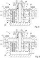
- Fig. 5 illustrates the first cross section of the attachment module 1 illustrated in Fig. 4 in which the locking member 9 has been moved to the unlocking position.
- the locking assembly 7 has been controlled from the locked state to the unlocked state in Fig. 5 .
- the locking assembly 7 comprises a first toothed section 11 arranged on the arm section 5, a second toothed section 12 arranged on the tool section 6, and a third toothed section 13 arranged on the locking member 9.
- the first toothed section 11 is a section of a first plate-like member attached to the arm section 5.
- the first plate-like member may be attached to the arm section 5 via a number of bolts.
- the second toothed section 12 is a section of a second plate-like member attached to the tool section 6.
- the second plate-like member may be attached to the tool section 6 via a number of bolts.
- the second toothed section 12 is arranged adjacent to the first toothed section 11.
- the third toothed section 13 engages with both of the first and second toothed sections 11, 12 when the locking member 9 is in the locking position.
- the tool section 6 is locked from rotating relative to the arm section 5 around the rotation axis Ra.
- the second toothed section 12 is locked from rotating relative to the first toothed section 11 by the third toothed section 13 engaging both of the first and second toothed sections 11, 12.
- the third toothed section 13 engages only with the second toothed section 12 when the locking member 9 is in the unlocking position.
- the tool section 6 is free to rotate relative to the arm section 5 around the rotation axis Ra.
- the second toothed section 12 is free to rotate relative to the first toothed section 11 because the third toothed section 13 engages with only one of the first and second toothed sections 11, 12.
- the third toothed section 13 engages only with the second toothed section 12 when the locking member 9 is in the unlocking position.
- the third toothed section 13 may be configured to only engage with the first toothed section 11 when the locking member 9 is in the unlocking position.
- Fig. 6 illustrates a second cross section of the attachment module 1 illustrated in Fig. 2 - Fig. 5 .
- the cross section is made in a plane comprising the rotation axis Ra in Fig. 6 .
- simultaneous reference is made to Fig. 1 - Fig. 6 , if not indicated otherwise.
- each of the first, second and third toothed sections 11, 12, 13 circumscribes the rotation axis Ra.
- each of the first and second toothed sections 11, 12 comprises internal teeth 11', 12' whereas the third toothed section 13 comprises external teeth 13'.
- the feature that each of the first and second toothed sections 11, 12 comprises internal teeth 11', 12' means that the internal teeth 11', 12' face towards a geometrical centre of the respective first and second toothed sections 11, 12.
- the geometrical centre of the respective first and second toothed sections 11, 12 coincides with the rotation axis Ra.
- the feature that the third toothed section 13 comprises external teeth 13' means that the external teeth 13' face outward of a geometrical centre of the third toothed section 13. According to the illustrated embodiments, the geometrical centre of the third toothed section 13 coincides with the rotation axis Ra.
- the third toothed section 13 is a section of an element arranged inside of the first and second toothed sections 11, 12, wherein the element is attached to the locking member 9 to form one moving part.
- the third toothed section 13 can be said to be a toothed section of the locking member 9, wherein the locking member 9 is arranged inside the first and second toothed sections 11, 12.
- Fig. 6 the locking member 9 is illustrated in the locking position and the locking assembly 7 is consequently illustrated in the locked state.
- Fig. 7 illustrates the second cross section of the attachment module 1 illustrated in Fig. 6 in which the locking member 9 has been moved to the unlocking position.
- the locking assembly 7 has been controlled from the locked state to the unlocked state in Fig. 7 .
- the locking member 9 is movable in directions parallel to the rotation axis Ra between the locking and unlocking positions.
- Fig. 8 illustrates an enlarged cross section of the actuator assembly 10 of the attachment module 1 illustrated in Fig. 2 - Fig. 7 .
- the cross section is made in a plane comprising the rotation axis Ra in Fig. 8 .
- the locking member 9 is illustrated in the locking position and the locking assembly 7 is consequently illustrated in the locked state.
- the actuator assembly 10 comprises an actuator 20.
- the actuator 20 is configured to move the locking member 9 to the unlocking position when activated.
- the actuator assembly 10 comprises a spring element 23.
- the spring element 23 configured to bias the locking member 9 towards the locking position.
- the actuator assembly 10 may comprise a greater number of spring elements 23, such as a number between two and twelve, wherein each of the number of spring elements 23 is configured to bias the locking member 9 towards the locking position.
- Fig. 9 illustrates the enlarged cross section of the actuator assembly 10 illustrated in Fig. 8 in which the actuator 20 has displaced the locking member 9 to the unlocking position.
- the locking assembly 7 is illustrated in the unlocked state.
- the third toothed section 13 only engages the second toothed section 12 when the locking member 9 is in the unlocking position. Moreover, as can be seen in Fig. 9 , the spring element 23 has been compressed upon the movement of the locking member 9 from the locked position to the unlocking position.
- the actuator 20 is of hydraulic type and is configured to move the locking member 9 to the unlocking position when being fed with a hydraulic pressure.
- the biasing force of the spring element 23, or by the number of spring elements 23, forces the locking member 9 to the locked state when the hydraulic pressure is released.
- the actuator 20 comprises a centre body 25 attached to a portion 27 of the arm section 5 by a fastening element 29 extending into a hole 31 of the centre body 25.
- the fastening element 29 is a bolt, i.e., an elongated object with a threaded portion.
- the actuator 20 comprises a hydraulic connection 33 and a hydraulic chamber 35, 35' configured to increase in volume when being fed with a hydraulic pressure via the hydraulic connection 33 to move the locking member 9 towards the unlocking position.
- the hydraulic connection 33 indicated in Fig. 8 and 9 is connected to the control arrangement 21 of the excavator machine 4 illustrated in Fig. 1 via a hydraulic circuit 38 of the excavator machine 4.
- the hydraulic chamber 35, 35' is fluidly connected to the hydraulic connection 33 via a space 34 between the fastening element 29 and the hole 31 of the centre body 25.
- a threaded portion of the interface between the fastening element 29 and the hole 31 is utilized for fluidly connecting the hydraulic chamber 35, 35' to the hydraulic connection 33. In this manner, a space efficient solution is provided for connecting hydraulic chamber 35, 35' to the hydraulic connection 33.
- the rotation axis Ra extends through the actuator assembly 10 and extends through the fastening element 29.
- the actuator 20 of the actuator assembly 10 may be configured to move the locking member 9 to the locking position when activated.
- the actuator assembly 10 may comprise a number of spring elements configured to bias the locking member 9 towards the unlocking position.
- the actuator 20 of the actuator assembly 10 may be controllable to move the locking member 9 between the locked and unlocked positions, i.e., in both directions.
- the actuator assembly 10 may lack spring elements 23 configured to bias the locking member 9 to one of the locking and unlocking positions.
- Fig. 1 - Fig. 9 if not indicated otherwise.
- tool section 6 is free to rotate relative to the arm section 5 around the rotation axis Ra when the locking assembly 7 is in the unlocked state.
- the attachment module 1 is provided with some fixed locking positions of the tool section 6 relative to the arm section 5.
- the number of fixed locking positions of the tool section 6 relative to the arm section 5 is determined by the number of teeth 11', 12', 13' of the first, second, and third toothed sections 11, 12, 13.
- each of the first, second, and third toothed sections 11, 12, 13 comprises twenty-four teeth 11', 12', 13'.
- the attachment module 1 is provided with twenty-four fixed locking positions of the tool section 6 relative to the arm section 5.
- the attachment module 1 may be provided with another number of fixed locking positions and number of teeth 11', 12', 13' of the respective first, second, and third toothed sections 11, 12, 13, such as for example a number between eight and one hundred, or a number between twelve and forty-eight.
- Fig. 10 illustrates a method of rotating a tool relative to an excavator arm of an excavator machine, the excavator machine comprising the excavator arm, an attachment module, and the tool.
- the excavator machine may be an excavator machine 4 explained with reference to Fig. 1 and the attachment module may be an attachment module 1 explained with reference to Fig. 1 - Fig. 9 . Therefore, below, simultaneous reference is made to Fig. 1 - Fig. 10 , if not indicated otherwise.
- the method 100 is a method 100 of rotating a tool 2 relative to an excavator arm 3 of an excavator machine 4, the excavator machine 4 comprising the excavator arm 3, an attachment module 1, and the tool 2.
- the attachment module 1 comprises an arm section 5 attached to a distal end 3' of the excavator arm 3 and a tool section 6 attached to the tool 2 allow the tool 2 to operate in a main operation direction d1 by a movement of the excavator arm 3 in the main operation direction d1.
- the tool section 6 is rotatably arranged relative to the arm section 5 around a rotation axis Ra.
- the attachment module 1 comprises a locking assembly 7 controllable between a locked state, in which the locking assembly 7 locks the tool section 6 from rotating relative to the arm section 5 around the rotation axis Ra, and an unlocked state, in which the locking assembly 7 unlocks the tool section 6 from the arm section 5 such that the tool section 6 is free to rotate relative to the arm section 5 around the rotation axis Ra.
- the method 100 comprises the steps of:
- the step of rotating 120 the tool 2 relative to an excavator arm 3 by applying an external torque onto the tool 2 around the rotation axis Ra may comprise comprises the steps of:
- control arrangement 21 may be configured to perform any one of the method steps 110, 120, 121, and 122 of the method 100.
- Fig. 11 illustrates a computer-readable medium 200 comprising instructions which, when executed by a computer, cause the computer to carry out the method 100 according to some embodiments of the present disclosure.
- the computer-readable medium 200 comprises a computer program comprising instructions which, when the program is executed by a computer, cause the computer to carry out the method 100 according to some embodiments.
- the method 100 of rotating a tool 2 relative to an excavator arm 3 of an excavator machine 4 may be implemented by programmed instructions.
- These programmed instructions are typically constituted by a computer program, which, when it is executed in the control arrangement 21, ensures that the control arrangement 21 carries out the desired control, such as the method steps 110, 120, 121, and 122 of the method 100 described herein.
- the computer program is usually part of a computer program product 200 which comprises a suitable digital storage medium on which the computer program is stored.
- the control arrangement 21 may comprise a calculation unit which may take the form of substantially any suitable type of processor circuit or microcomputer, e.g., a circuit for digital signal processing (digital signal processor, DSP), a Central Processing Unit (CPU), a processing unit, a processing circuit, a processor, an Application Specific Integrated Circuit (ASIC), a microprocessor, or other processing logic that may interpret and execute instructions.
- a calculation unit may represent a processing circuitry comprising a plurality of processing circuits, such as, e.g., any, some or all of the ones mentioned above.
- the control arrangement 21 may further comprise a memory unit, wherein the calculation unit may be connected to the memory unit, which may provide the calculation unit with, for example, stored program code and/or stored data which the calculation unit may need to enable it to do calculations.
- the calculation unit may also be adapted to store partial or final results of calculations in the memory unit.
- the memory unit may comprise a physical device utilised to store data or programs, i.e., sequences of instructions, on a temporary or permanent basis. According to some embodiments, the memory unit may comprise integrated circuits comprising silicon-based transistors.
- the memory unit may comprise e.g. a memory card, a flash memory, a USB memory, a hard disc, or another similar volatile or non-volatile storage unit for storing data such as e.g. ROM (Read-Only Memory), PROM (Programmable Read-Only Memory), EPROM (Erasable PROM), EEPROM (Electrically Erasable PROM), etc. in different embodiments.
- the control arrangement 21 may be connected to components of the excavator machine 4, the excavator arm 3, and/or the attachment module 1, for receiving and/or sending input and output signals.
- These input and output signals may comprise waveforms, pulses, or other attributes which the input signal receiving devices can detect as information and which can be converted to signals processable by the control arrangement 21. These signals may then be supplied to the calculation unit.
- One or more output signal sending devices may be arranged to convert calculation results from the calculation unit to output signals for conveying to other parts of the vehicle's control system and/or the component or components for which the signals are intended.
- Each of the connections to the respective components of the excavator machine 4, the excavator arm 3, and/or the attachment module 1, for receiving and sending input and output signals may take the form of one or more from among a hydraulic circuit, a cable, a data bus, e.g., a CAN (controller area network) bus, a MOST (media orientated systems transport) bus or some other bus configuration, or a wireless connection.
- a hydraulic circuit e.g., a CAN (controller area network) bus, a MOST (media orientated systems transport) bus or some other bus configuration, or a wireless connection.
- the excavator machine 4 comprises a control arrangement 21 but might alternatively be implemented wholly or partly in two or more control arrangements or two or more control units.
- Control systems in modern excavator machines 4 can comprise a communication bus system consisting of one or more communication buses for connecting a number of electronic control units (ECUs), or controllers, to various components on board the excavator machine 4.
- ECUs electronice control units
- Such a control system may comprise a large number of control units and taking care of a specific function may be shared between two or more of them.
- Excavator machines 4 of the type here concerned are therefore often provided with significantly more control arrangements 21 than depicted in Fig. 1 , as one skilled in the art will surely appreciate.
- the computer program product 200 may be provided for instance in the form of a data carrier carrying computer program code for performing at least some of the method steps 110, 120, 121, and 122 of the method 100 according to some embodiments when being loaded into one or more calculation units of the control arrangement 21.
- the data carrier may be, e.g. a CD ROM disc, as is illustrated in Fig.
- ROM read-only memory
- PROM programable read-only memory
- EPROM erasable PROM
- flash memory an EEPROM (electrically erasable PROM)
- hard disc a hard disc
- EEPROM electrically erasable PROM
- hard disc a hard disc
- optical storage device e.g., a magnetic tape that may hold machine readable data in a non-transitory manner.
- the computer program product may furthermore be provided as computer program code on a server and may be downloaded to the control arrangement 21 remotely, e.g., over an Internet or an intranet connection, or via other wired or wireless communication systems.
- substantially perpendicular to may encompass that the angle between the objects referred to is within the range of 80 - 100 degrees or is within the range of 83 - 97 degrees.
Landscapes
- Engineering & Computer Science (AREA)
- Mechanical Engineering (AREA)
- Mining & Mineral Resources (AREA)
- Civil Engineering (AREA)
- General Engineering & Computer Science (AREA)
- Structural Engineering (AREA)
- Operation Control Of Excavators (AREA)
- Earth Drilling (AREA)
Abstract
Description
- The present disclosure relates to an attachment module configured to attach a tool to a distal end of an excavator arm. The present disclosure further relates to an excavator arm, an excavator comprising an excavator arm, a method of rotating a tool relative to an excavator arm of an excavator, a computer program, and a computer-readable medium.
- Excavators and backhoes are examples of excavator machines which use an excavator arm and a tool, such as a bucket, attached to a distal end of the excavator arm to perform various tasks such as digging, levelling, performing forestry work, demolition, and the like. An excavator is usually a heavy construction equipment comprising a cab for an operator on a rotating platform known as an upper structure. The upper structure can be arranged on an undercarriage with tracks or wheels. A backhoe, also called rear actor or back actor, is a type of excavating equipment typically mounted on the back of a tractor or front loader.
- The excavator arm of an excavator machine is normally powered by a number of hydraulic cylinders such that the distal end of the excavator arm can be moved to perform a task with a tool attached to the distal end of the excavator arm. The excavator arm normally comprises a tool attachment section for a tool at a distal portion of the excavator arm to which a tool, such as a bucket can be arranged. An excavator arm typically comprises a so-called boom which is an arm section closest to the vehicle, and a so-called stick which is attached to the boom. The tool attachment section is usually attached to the stick.
- Excavator machines, such as excavators and backhoes, come in various sizes and prize ranges. Most excavator machines can be provided with an excavator arm capable of rotating the tool attachment section through 360 degrees relative to the stick using a hydraulic motor. In this manner, a more versatile excavator arm is provided because the angle of the operation direction of the tool can be varied which can increase the flexibility and the precision of the operation of the tool. However, such a function can add costs, complexity, and weight to the excavator arm and thereby also to the excavator machine comprising the excavator arm.
- Moreover, some different types of modules are available on the market which comprise a hydraulic motor allowing rotation of a tool section of an excavator arm and which can be mounted to existing excavator arms which lacks the above-mentioned rotator function. Such modules are commonly referred to as a tiltrotator and are also known under a number of trade names. These types of modules can provide a more versatile excavator arm because they allow variation of the angle of the operation direction of the tool which can increase the flexibility and the precision of the operation of the tool. However, these modules may be costly and complex to manufacture and for many users, these modules may be considered to be too expensive, especially in cases where it is intended to be used on a smaller type of excavator machine.
- Furthermore, the weight and size of the above-mentioned type of module may not be suited for use on a smaller type of excavator machine.
- In addition, generally, on today's consumer market, it is an advantage if products comprise different features and functions while the products have conditions and/or characteristics suitable for being manufactured and assembled in a cost-efficient manner.
- It is an object of the present invention to overcome, or at least alleviate, at least some of the above-mentioned problems and drawbacks, such as by providing a simpler and/or more cost-efficient solution for allowing a variation of the angle of the tool of an excavator arm.
- According to a first aspect of the invention, the object is achieved by an attachment module configured to attach a tool to a distal end of an excavator arm. The attachment module comprises an arm section comprising a first attachment arrangement for attaching the arm section to the distal end of the excavator arm, and a tool section comprising a second attachment arrangement for attaching the tool to the tool section. The tool section is rotatably arranged relative to the arm section around a rotation axis. The attachment module comprises a locking assembly controllable between a locked state in which the locking assembly locks the tool section from rotating relative to the arm section around the rotation axis, and an unlocked state in which the locking assembly unlocks the tool section from the arm section such that the tool section is free to rotate relative to the arm section around the rotation axis.
- Since the tool section is rotatably arranged relative to the arm section around the rotation axis and since the attachment module comprises the locking assembly controllable between the locked and unlocked states, an attachment module is provided allowing a change in the operation direction of a tool attached to the tool section relative to a distal end of an excavator arm in a manner circumventing the need for a hydraulic motor for rotating the tool section.
- That is, a user may rotate the tool section relative to the arm section, and thus also a tool relative to a distal end of an excavator arm, by controlling the locking assembly to the unlocked state and applying an external force or torque onto the tool section, or to a tool attached to the tool section. Since the tool section is free to rotate relative to the arm section around the rotation axis when the locking assembly is in the unlocked state, such an external force or torque can rotate the tool section relative to the distal end of the excavator arm.
- The external force or torque may be applied to the tool section, or to a tool attached to the tool section, by controlling the excavator arm such that the tool or tool section abuts against an external surface and controlling the excavator arm such that the arm section of the attachment module is moved relative to the external surface.
- When a wanted angle of the tool section relative to the arm section is obtained, the user may control the locking assembly to the locked state to lock the tool section from further rotating relative to the arm section.
- Since the attachment module allows a change in the operation direction of a tool attached to the tool section relative to a distal end of an excavator arm in a manner circumventing the need for a hydraulic motor for rotating the tool section, a simple and efficient attachment module is provided having conditions for improving flexibility and precision of the operation of an excavator machine while having conditions and characteristics suitable for being manufactured and assembled in a cost-efficient manner.
- Furthermore, due to the features of the attachment module, an attachment module is provided capable of allowing a change in the operation direction of a tool attached to the tool section, while having conditions for being compact and having conditions for having a low weight. Therefore, the attachment module according to the embodiments herein can be made suitable for use on smaller types of excavator machines as well as for use on larger or mid-sized excavator machines.
- Accordingly, an attachment module is provided overcoming, or at least alleviating, at least some of the above-mentioned problems and drawbacks. As a result, the above-mentioned object is achieved.
- Optionally, the attachment module comprises an input unit connectable to the locking assembly for controlling the locking assembly between the locked and unlocked states based on input from the input unit. Thus, due to these features, the input unit can be arranged in an operator area of an excavator machine, such as a cab or other type of operator area of the excavator machine, and can be connected to the locking assembly of the attachment module. In this manner, a user is allowed to change the operation direction of a tool attached to the tool section relative to a distal end of an excavator arm without having to leave the operator area of the excavator machine.
- Optionally, the second attachment arrangement is configured to attach the tool to the tool section to allow the tool to operate in a main operation direction by a movement of the excavator arm in the main operation direction, and wherein the rotation axis is substantially perpendicular to the main operation direction of the tool. Thereby, an attachment module is provided having conditions for even further improving the flexibility and the precision of the operation of an excavator machine while having conditions and characteristics suitable for being manufactured and assembled in a cost-efficient manner.
- Optionally, the tool section is free to rotate more than 360 degrees relative to the arm section around the rotation axis when the locking assembly is in the unlocked state. Thereby, an attachment module is provided allowing a full rotation of a tool relative to a distal end of an excavator arm thereby further improving flexibility and precision of the operation of an excavator machine while having conditions and characteristics suitable for being manufactured and assembled in a cost-efficient manner.
- Optionally, the locking assembly comprises a locking member and an actuator assembly operably connected to the locking member to move the locking member between a locking position, in which the locking assembly assumes the locked state, and an unlocking position, in which the locking assembly assumes the unlocked state. Thereby, a simple, efficient, and reliable locking assembly is provided.
- Optionally, the locking assembly further comprises a first toothed section arranged on the arm section, a second toothed section arranged on the tool section, and a third toothed section arranged on the locking member, and wherein the third toothed section engages with both of the first and second toothed sections when the locking member is in the locking position and engages with only one of the first and second toothed sections when the locking member is in the unlocking position. Thereby, a locking assembly is provided having conditions for being simple, robust, and durable. Moreover, an attachment module is provided having conditions for having a low weight and being compact.
- Optionally, the third toothed section engages with the second toothed section when the locking member is in the unlocking position. Thereby, a locking assembly is provided having conditions for being simple, compact, robust, and durable.
- Optionally, each of the first, second and third toothed sections circumscribes the rotation axis. Thereby, a locking assembly is provided having conditions for being simple, compact, robust, and durable.
- Optionally, each of the first and second toothed sections comprises internal teeth and wherein the third toothed section comprises external teeth. Thereby, conditions are provided for a simple, small sized, and low-cost actuator assembly. This is because the third toothed section is arranged on the locking member.
- Optionally, the rotation axis extends through the actuator assembly. Thereby, conditions are provided for a simple, small sized, and low-cost actuator assembly.
- Optionally, the locking member is movable in directions parallel to the rotation axis between the locking and unlocking positions. Thereby, conditions are provided for a compact, simple, and low-cost actuator assembly.
- Optionally, the actuator assembly comprises an actuator configured to move the locking member to one of the locking and unlocking positions when activated, and wherein the actuator assembly comprises at least one spring element configured to bias the locking member towards the other of the locking position and the unlocking position. Thereby, conditions are provided for an even simpler actuator assembly. This is because the actuator is only required to apply a force onto the locking member in one direction.
- Optionally, the actuator assembly comprises an actuator of hydraulic type configured to move the locking member to one of the locking and unlocking positions when being fed with a hydraulic pressure. Thereby, a simple and robust actuator assembly is provided having conditions and characteristics suitable for being manufactured and assembled in a cost-efficient manner.
- Optionally, the actuator comprises a centre body attached to a portion of the arm section by a fastening element extending into a hole of the centre body. Thereby, a simple and robust actuator assembly is provided having conditions and characteristics suitable for being manufactured and assembled in a cost-efficient manner.
- Optionally, the actuator comprises a hydraulic connection and a hydraulic chamber configured to increase in volume when being fed with a hydraulic pressure via the hydraulic connection to move the locking member, and wherein the hydraulic chamber is fluidly connected to the hydraulic connection via a space between the fastening element and the hole of the centre body. Thereby, an actuator assembly is provided having conditions for being simple, robust, and compact. This is because the space between the fastening element and the hole of the centre body is utilized for conduction hydraulic fluid.
- Optionally, the rotation axis extends through the fastening element. Thereby, a simple, robust, and compact actuator assembly is provided having conditions and characteristics suitable for being manufactured and assembled in a cost-efficient manner
- According to a second aspect of the invention, the object is achieved by an excavator arm comprising an attachment module according to some embodiments, wherein the attachment module is attached to a distal end of the excavator arm, and wherein the tool section of the attachment module is free to rotate relative to the excavator arm around the rotation axis when the locking assembly is in the unlocked state.
- Since the tool section of the attachment module is rotatably arranged relative to the arm section around the rotation axis and since the attachment module comprises the locking assembly controllable between the locked and unlocked states, an excavator arm is provided allowing a change in the operation direction of a tool attached to the tool section relative to a distal end of an excavator arm in a manner circumventing the need for a hydraulic motor for rotating the tool section.
- That is, a user may rotate the tool section relative to the arm section, and thus also a tool relative to a distal end of the excavator arm, by controlling the locking assembly to the unlocked state and applying an external force or torque onto the tool section, or to a tool attached to the tool section. Since the tool section is free to rotate relative to the arm section around the rotation axis when the locking assembly is in the unlocked state, such an external force or torque can rotate the tool section relative to the distal end of the excavator arm.
- Since the attachment module of the excavator arm allows a change in the operation direction of a tool attached to the tool section relative to a distal end of an excavator arm in a manner circumventing the need for a hydraulic motor for rotating the tool section, a simple and efficient excavator arm is provided having conditions for improving flexibility and precision of the operation of an excavator machine comprising the excavator arm while having conditions and characteristics suitable for being manufactured and assembled in a cost-efficient manner.
- Accordingly, excavator arm is provided overcoming, or at least alleviating, at least some of the above-mentioned problems and drawbacks. As a result, the above-mentioned object is achieved.
- According to a third aspect of the invention, the object is achieved by an excavator machine comprising an excavator arm according to some embodiments.
- Since the excavator machine comprises an excavator arm with an attachment module allowing a change in the operation direction of a tool attached to the tool section relative to a distal end of an excavator arm in a manner circumventing the need for a hydraulic motor for rotating the tool section, a simple and efficient excavator machine is provided having conditions for improved flexibility and precision of the operation while having conditions for being manufactured and assembled in a cost-efficient manner.
- Accordingly, excavator machine is provided overcoming, or at least alleviating, at least some of the above-mentioned problems and drawbacks. As a result, the above-mentioned object is achieved.
- Optionally, the locking assembly of the attachment module comprises a locking member and an actuator assembly operably connected to the locking member to move the locking member between a locking position, in which the locking assembly assumes the locked state, and an unlocking position, in which the locking assembly assumes the unlocked state, wherein the excavator machine comprises an operator environment with an input unit for an operator of the excavator machine, and wherein the input unit is operably connected to the actuator assembly. Thereby, a user of the excavator machine is allowed to change the operation direction of a tool attached to the tool section relative to a distal end of the excavator arm without having to leave the operator area of the excavator machine. In this manner, a user-friendly excavator machine is provided having conditions and characteristics suitable for being manufactured and assembled in a cost-efficient manner.
- According to a fourth aspect of the invention, the object is achieved by a method of rotating a tool relative to an excavator arm of an excavator machine, the excavator machine comprising the excavator arm, an attachment module, and the tool, wherein the attachment module comprises an arm section attached to a distal end of the excavator arm and a tool section attached to the tool, wherein the tool section is rotatably arranged relative to the arm section around a rotation axis, and wherein the attachment module comprises a locking assembly controllable between a locked state, in which the locking assembly locks the tool section from rotating relative to the arm section around the rotation axis, and an unlocked state, in which the locking assembly unlocks the tool section from the arm section such that the tool section is free to rotate relative to the arm section around the rotation axis. The method comprises the steps of:
- controlling the locking assembly to the unlocked state, and
- rotating the tool relative to an excavator arm by applying an external torque onto the tool around the rotation axis.
- Thereby, a method is provided allowing a change in the operation direction of a tool attached to the tool section relative to a distal end of an excavator arm in a manner circumventing the need for a hydraulic motor for rotating the tool section. As a result, a method is provided having conditions for improving flexibility and precision of the operation of an excavator machine in a cost-efficient manner.
- Accordingly, method is provided overcoming, or at least alleviating, at least some of the above-mentioned problems and drawbacks. As a result, the above-mentioned object is achieved.
- Optionally, the step of rotating the tool relative to an excavator arm by applying an external torque onto the tool around the rotation axis comprises the steps of:
- controlling the excavator arm such that the tool abuts against an external surface, and
- controlling the excavator arm such that the arm section of the attachment module is moved relative to the external surface.
- Thereby, a method is provided capable of obtaining a wanted angle of the tool section, and a tool attached thereto, without requiring a motor or other type of arrangement for rotating the tool section relative to the arm section.
- It will be appreciated that the various embodiments described for the method are all combinable with the control arrangement as described herein. That is, the control arrangement as described herein may be configured to perform any one of the method steps of the method according to the fourth aspect of the invention.
- According to a fifth aspect of the invention, the object is achieved by a computer program comprising instructions which, when the program is executed by a computer, cause the computer to carry out the method according to some embodiments of the present disclosure. Since the computer program comprises instructions which, when the program is executed by a computer, cause the computer to carry out the method according to some embodiments described herein, a computer program is provided which provides conditions for overcoming, or at least alleviating, at least some of the above-mentioned drawbacks. As a result, the above-mentioned object is achieved.
- According to a sixth aspect of the invention, the object is achieved by a computer-readable medium comprising instructions which, when executed by a computer, cause the computer to carry out the method according to some embodiments of the present disclosure. Since the computer-readable medium comprises instructions which, when the program is executed by a computer, cause the computer to carry out the method according to some embodiments described herein, a computer-readable medium is provided which provides conditions for overcoming, or at least alleviating, at least some of the above-mentioned drawbacks. As a result, the above-mentioned object is achieved.
- Further features of, and advantages with, the present invention will become apparent when studying the appended claims and the following detailed description.
- Various aspects of the invention, including its particular features and advantages, will be readily understood from the example embodiments discussed in the following detailed description and the accompanying drawings, in which:
-
Fig. 1 schematically illustrates an excavator machine according to some embodiments, -
Fig. 2 illustrates a perspective view of anattachment module 1 according to embodiments illustrated inFig. 1 , -
Fig. 3 illustrates the attachment module illustrated inFig. 2 in which a tool section has been rotated relative to an arm section around a rotation axis, -
Fig. 4 illustrates a first cross section of the attachment module illustrated inFig. 2 and Fig. 3 -
Fig. 5 illustrates the first cross section of the attachment module illustrated inFig. 4 in which a locking member has been moved to an unlocking position, -
Fig. 6 illustrates a second cross section of the attachment module illustrated inFig. 2 - Fig. 5 , -
Fig. 7 illustrates the second cross section of the attachment module illustrated inFig. 6 in which the locking member has been moved to the unlocking position, -
Fig. 8 illustrates an enlarged cross section of an actuator assembly of the attachment module illustrated inFig. 2 - Fig. 7 , -
Fig. 9 illustrates the enlarged cross section of the actuator assembly illustrated inFig. 8 in which an actuator has displaced the locking member to the unlocking position, -
Fig. 10 illustrates a method of rotating a tool relative to an excavator arm of an excavator machine, and -
Fig. 11 illustrates a computer-readable medium. - Aspects of the present invention will now be described more fully. Like numbers refer to like elements throughout. Well-known functions or constructions will not necessarily be described in detail for brevity and/or clarity.
-
Fig. 1 schematically illustrates anexcavator machine 4 according to some embodiments comprising anexcavator arm 3. According to the illustrated embodiments, theexcavator machine 4 is a small sized excavator. According to further embodiments, theexcavator machine 4, as referred to herein, may be another type ofexcavator machine 4 comprising anexcavator arm 3, such as a mid- or large-sized excavator, a backhoe, or the like. - According to the illustrated embodiments, the
excavator machine 4 comprises anundercarriage 14 withcontinuous tracks 16 for moving theexcavator machine 4. According to further embodiments, theexcavator machine 4 may comprise another type of propulsion units for moving theexcavator machine 4 such as wheels. Moreover, according to the illustrated embodiments, theexcavator machine 4 comprises anupper structure 18 with acab 22 for an operator of theexcavator machine 4. Theupper structure 18 is sometimes referred to as a house. Thecab 22 comprises anoperator environment 40. - According to the illustrated embodiments, the
upper structure 18 can be rotated relative to theundercarriage 14 around an axis of rotation Ax by a hydraulic motor of theexcavator machine 4. The hydraulic motor of theexcavator machine 4 is not illustrated inFig. 1 for reasons of brevity and clarity. - The
excavator arm 3 comprises afirst arm unit 24 and asecond arm unit 26 pivotally attached to thefirst arm unit 24. Thefirst arm unit 24 may also be referred to as a boom and thesecond arm unit 26 may also be referred to as a stick. Thefirst arm unit 24 of theexcavator arm 3 is attached to theupper structure 18 of theexcavator machine 4 through afirst pivot 28 also known as a king-post. Thefirst pivot 28 allows theexcavator arm 3 to pivot left and right as seen from theoperator environment 40 of theexcavator machine 4. Thefirst arm unit 24 of theexcavator arm 3 is also attached to theupper structure 18 of theexcavator machine 4 through asecond pivot 32 allowing theexcavator arm 3 to pivot up and down as seen from theoperator environment 40 of theexcavator machine 4. Theexcavator arm 3 further comprises alinkage unit 30 attached to thesecond arm unit 26. - Moreover, the
excavator arm 3 comprises a number ofhydraulic units excavator arm 3. In more detail, theexcavator arm 3 comprises a firsthydraulic unit 61 configured to move, i.e., pivot, thefirst arm unit 24, and thus theexcavator arm 3, around thefirst pivot 28. Moreover, theexcavator arm 3 comprises a secondhydraulic unit 62 configured to move, i.e., pivot, thefirst arm unit 24, and thus theexcavator arm 3, around thesecond pivot 32. Furthermore, theexcavator arm 3 comprises a thirdhydraulic unit 63 configured to move, i.e., pivot, thesecond arm unit 26 relative to thefirst arm unit 24. Moreover, theexcavator arm 3 comprises a fourthhydraulic unit 64 configured to move, i.e., pivot, thelinkage unit 30 relative to thesecond arm unit 26. - Each
hydraulic unit excavator machine 4 further comprises acontrol arrangement 21 configured to control thehydraulic unit control unit 42 arranged in theoperator environment 40 of theexcavator machine 4. According to the illustrated embodiments, thecontrol arrangement 21 is ahydraulic control arrangement 21 but may alternatively or additionally comprise one or more electrical components, units, or systems, as is further explained herein. - The
excavator machine 4 illustrated inFig. 1 comprises anattachment module 1, according to embodiments herein, and atool 2 attached to a distal end 3' of theexcavator arm 3 via theattachment module 1. According to the illustrated embodiments, the distal end 3' of theexcavator arm 3 is a distal end of thesecond arm unit 26. Moreover, thetool 2 according to the illustrated embodiments is a bucket, i.e., atool 2 which can be used for digging. Thetool 2 is associated with a main operation direction d1. In cases where thetool 2 is a bucket, the main operation direction d1 coincides with a facing direction of an open portion of the bucket. -
Fig. 2 illustrates a perspective view of theattachment module 1 according to the embodiments illustrated inFig. 1 . Below, simultaneous reference is made toFig. 1 - Fig. 2 , if not indicated otherwise. As mentioned, theattachment module 1 is configured to attach atool 2 to a distal end 3' of anexcavator arm 3. - The
attachment module 1 comprises anarm section 5 comprising afirst attachment arrangement 5', 5" for attaching thearm section 5 to the distal end 3' of theexcavator arm 3. According to the illustrated embodiments, thefirst attachment arrangement 5', 5" comprises a first pair of holes 5' each configured to accommodate a journal for connecting thearm section 5 to a connectingelement 36 connected to thelinkage unit 30 of theexcavator arm 3. Moreover, according to the illustrated embodiments, thefirst attachment arrangement 5 comprises a second pair ofholes 5" each configured to accommodate a journal for connecting thearm section 5 to thesecond arm unit 26 of theexcavator arm 3. - The
attachment module 1 further comprises atool section 6. Thetool section 6 comprises asecond attachment arrangement tool 2 to thetool section 6 to allow thetool 2 to operate in a main operation direction d1 by a movement of theexcavator arm 3 in the main operation direction d1. According to the illustrated embodiments, thesecond attachment arrangement tool section 6 comprises a first pair ofcontrollable locking rods 6' and a pair ofrecesses 6". The first pair ofcontrollable locking rods 6' and the pair ofrecesses 6" are configured to engage with structures of atool 2 so as to attach thetool 2 to thetool section 6 of theattachment module 1. - The
controllable locking rods 6' may be controllable between a locked state, in which thetool 2 is locked to thetool section 6 and an unlocked state, in which thetool 2 is unlocked from thetool section 6 of theattachment module 1. - As is further explained herein, the
tool section 6 is rotatably arranged relative to thearm section 5 around a rotation axis Ra. According to the illustrated embodiments, the rotation axis Ra is substantially perpendicular to the main operation direction d1 of thetool 2. - Moreover, as is further explained herein, the
attachment module 1 comprises a lockingassembly 7 controllable between a locked state in which the lockingassembly 7 locks thetool section 6 from rotating relative to thearm section 5 around the rotation axis Ra and an unlocked state in which the lockingassembly 7 unlocks thetool section 6 from thearm section 5 such that thetool section 6 is free to rotate relative to thearm section 5 around the rotation axis Ra. - In this manner, a more
versatile excavator machine 4 is provided in a simple and cost-efficient manner, as is further explained herein. -
Fig. 3 illustrates theattachment module 1 illustrated inFig. 2 in which thetool section 6 has been rotated relative to thearm section 5 around the rotation axis Ra. That is, as can be seen when comparingFig. 2 and Fig. 3 , thetool section 6 has been rotated relative to thearm section 5 around the rotation axis Ra such that the angle of thetool section 6 is different as measured relative to the rotation axis Ra. InFig. 3 , thetool section 6 has been rotated approximately 80 degrees relative to thearm section 5 around the rotation axis Ra from the position illustrated inFig. 2 . However, according to embodiments herein, thetool section 6 is free to rotate more than 360 degrees relative to thearm section 5 around the rotation axis Ra when the lockingassembly 7 is in the unlocked state. The feature that thetool section 6 is free to rotate relative to thearm section 5 means that no arrangement, structure, component, or system of theattachment module 1 prevents or restricts rotation oftool section 6 relative to thearm section 5 around the rotation axis Ra. Moreover, according to the illustrated embodiments, theattachment module 1 has no restrictions on where to start or stop rotation of thetool section 6 relative to thearm section 5 around the rotation axis Ra, other than some fixed locking positions of thetool section 6 relative to thearm section 5 explained below. Below, simultaneous reference is made toFig. 1 - Fig. 3 , if not indicated otherwise. - As is further explained herein, according to the illustrated embodiments, the locking
assembly 7 is controllable between the locked and unlocked state via aninput unit 41 for an operator of theexcavator machine 4. According to the illustrated embodiments, theinput unit 41 is arranged in theoperator environment 40 inside thecab 22. - The
tool 2 may be rotated relative to anexcavator arm 3 by applying an external torque onto thetool 2 around the rotation axis Ra. The external torque may be applied onto thetool 2 around the rotation axis Ra by controlling theexcavator arm 3 such that thetool 2 abuts against anexternal surface 50 and by controlling theexcavator arm 3 such that thearm section 5 of theattachment module 1 is moved relative to theexternal surface 50. - That is, an operator of the
excavator machine 4 may first control the lockingassembly 7 to the unlocked state and control theexcavator arm 3 such that thetool 2 abuts against anexternal surface 50 and control theexcavator arm 3 such that thearm section 5 of theattachment module 1 is moved relative to theexternal surface 50. Thearm section 5 of theattachment module 1 may be moved relative to theexternal surface 50 by controlling the firsthydraulic unit 61 to pivot thefirst arm section 24, and thus theexcavator arm 3, around thefirst pivot 28. As an alternative, or in addition, thearm section 5 of theattachment module 1 may be moved relative to theexternal surface 50 by controlling the hydraulic motor of theexcavator machine 4 to rotate theupper structure 18 relative to theundercarriage 14 around the axis of rotation Ax. In such a procedure, thesection 5 of theattachment module 1 is moved relative to theexternal surface 50 because theexcavator arm 3 is attached to theupper structure 18. As a further alternative, or in addition, thearm section 5 of theattachment module 1 may be moved relative to theexternal surface 50 by controlling theentire excavator machine 4 to move relative theexternal surface 50, such as by a control of at least one of thecontinuous tracks 16 of theexcavator machine 4. In this manner, the abutting contact between a portion of thetool 2 and theexternal surface 50 can apply a force onto thetool 2 in a direction transversal and off centre relative to the rotation axis Ra and a torque is thereby applied onto thetool 2 around the rotation axis Ra which rotates thetool section 6 relative to thearm section 5 around the rotation axis Ra. - When a wanted angle of the
tool section 6, and thus of thetool 2 attached to thetool section 6, is reached, the operator may control the lockingassembly 7 to the locked position to prevent further rotation of thetool section 6 relative to thearm section 5. In this manner, moreversatile excavator machine 4 is provided in a simple and cost-efficient manner allowing a user to utilize thetool 2 in a more versatile manner with higher flexibility and precision of the operation. - The
attachment module 1 according to the embodiments herein may be sold as a separate unit configured to be attached to a distal end 3' of anexcavator arm 3 of an already existingexcavator machine 4. A moreversatile excavator machine 4 can thus be provided in a simple and cost-efficient manner by mounting theattachment module 1 according to the embodiments herein to the distal end 3' of theexcavator arm 3. Possibly, theattachment module 1 according to the embodiments herein may be sold as a kit comprising theattachment module 1 and one or both of aninput unit 41 for controlling the lockingassembly 7 between the locked and unlocked state and acontrol arrangement 21 for controlling the lockingassembly 7 between the locked and unlocked state. - As understood from the herein described, the
attachment module 1 lacks a motor or another type of arrangement configured to rotate thetool section 6 relative to thearm section 5 around the rotation axis Ra. Instead, thetool section 6 can be rotated relative to thearm section 5 around the rotation axis Ra when the lockingassembly 7 is in the unlocked state by applying an external torque onto thetool section 6 or atool 2 attached thereto. This is because, thetool section 6 of theattachment module 1 is free to rotate relative to theexcavator arm 3 around the rotation axis Ra when the lockingassembly 7 is in the unlocked state. - Due to the features of the
attachment module 1, theattachment module 1 can be made compact and light weighted. Therefore, theattachment module 1 according to the embodiments herein can be made suitable for use on smaller types of excavator machines as well as for use on larger or mid-sized excavator machines. - Obviously, the
tool section 6 may be rotated relative to thearm section 5 around the rotation axis Ra in another manner than in the above described manner, for example using hands or gravity acting onto thetool section 6, gravity acting onto atool 2 attached to thetool section 6, and/or gravity acting onto matter accommodated in atool 2 attached to thetool section 6. - As is indicated in
Fig. 2 and Fig. 3 , theattachment module 1 according to the illustrated embodiments comprises a tilt axis Pa between thearm section 5 and thetool section 6 allowing thetool section 6 to be tilted around the tilt axis Pa to some degree relative to thearm section 5. Moreover, according to the illustrated embodiments, theattachment module 1 comprises a fifthhydraulic unit 65 controllable to tilt thetool section 6 relative to thearm section 5 around the tilt axis Pa. According to the illustrated embodiments, the fifthhydraulic unit 65 comprises a hydraulic cylinder and a hydraulic piston arranged in the hydraulic cylinder. Moreover, inFig. 1 , the fifthhydraulic unit 65 is operably connected to thecontrol unit 42 via thecontrol arrangement 21 of theexcavator machine 4. The tilt axis Pa and the fifthhydraulic unit 65 controllable to tilt thetool section 6 relative to thearm section 5 around the tilt axis Pa may be of conventional type. - As seen in
Fig. 2 and Fig. 3 , according to the illustrated embodiments, the rotation axis Ra is substantially perpendicular to the tilt axis Pa. Moreover, according to the illustrated embodiments, the rotation axis Ra extends through the tilt axis Pa. Furthermore, according to the illustrated embodiments, thetool section 6 is rotatably arranged relative to thearm section 5 in a rotation plane. The rotation plane of thetool section 6 is perpendicular to rotation axis Ra and is parallel to the tilt axis Pa regardless of a current tilt angle of thetool section 6 relative to thearm section 5 around the tilt axis Pa. -
Fig. 4 illustrates a first cross section of theattachment module 1 illustrated inFig. 2 and Fig. 3 . InFig. 4 , the cross section is made in a plane comprising the rotation axis Ra. Below, simultaneous reference is made toFig. 1 - Fig. 4 , if not indicated otherwise. - In
Fig. 4 , thefirst attachment arrangement 5', 5" and thesecond attachment arrangement attachment module 1 can be seen in more detail. Moreover, as can be seen inFig. 4 , the lockingassembly 7 comprises a lockingmember 9 and anactuator assembly 10 operably connected to the lockingmember 9. Theactuator assembly 10 is controllable to move the lockingmember 9 between a locking position, in which the lockingassembly 7 assumes the locked state, and an unlocking position, in which the lockingassembly 7 assumes the unlocked state. According to the illustrated embodiments, theactuator assembly 10 is operably connected to theinput unit 41 of theexcavator machine 4 via ahydraulic circuit 38 of theexcavator machine 4, as is further explained herein. - In
Fig. 4 , the lockingmember 9 is illustrated in the locking position and the lockingassembly 7 is thus illustrated in the locked state. -
Fig. 5 illustrates the first cross section of theattachment module 1 illustrated inFig. 4 in which the lockingmember 9 has been moved to the unlocking position. In other words, as compared toFig. 4 , the lockingassembly 7 has been controlled from the locked state to the unlocked state inFig. 5 . - As can be seen in
Fig. 4 and Fig. 5 , the lockingassembly 7 comprises a firsttoothed section 11 arranged on thearm section 5, a secondtoothed section 12 arranged on thetool section 6, and a thirdtoothed section 13 arranged on the lockingmember 9. According to the illustrated embodiments, the firsttoothed section 11 is a section of a first plate-like member attached to thearm section 5. The first plate-like member may be attached to thearm section 5 via a number of bolts. Likewise, the secondtoothed section 12 is a section of a second plate-like member attached to thetool section 6. The second plate-like member may be attached to thetool section 6 via a number of bolts. The secondtoothed section 12 is arranged adjacent to the firsttoothed section 11. - As can be seen in
Fig. 4 , the thirdtoothed section 13 engages with both of the first and secondtoothed sections member 9 is in the locking position. In this manner, thetool section 6 is locked from rotating relative to thearm section 5 around the rotation axis Ra. This is because the secondtoothed section 12 is locked from rotating relative to the firsttoothed section 11 by the thirdtoothed section 13 engaging both of the first and secondtoothed sections - As can be seen in
Fig. 5 , the thirdtoothed section 13 engages only with the secondtoothed section 12 when the lockingmember 9 is in the unlocking position. In this manner, thetool section 6 is free to rotate relative to thearm section 5 around the rotation axis Ra. This is because the secondtoothed section 12 is free to rotate relative to the firsttoothed section 11 because the thirdtoothed section 13 engages with only one of the first and secondtoothed sections toothed section 13 engages only with the secondtoothed section 12 when the lockingmember 9 is in the unlocking position. However, according to further embodiments, the thirdtoothed section 13 may be configured to only engage with the firsttoothed section 11 when the lockingmember 9 is in the unlocking position. -
Fig. 6 illustrates a second cross section of theattachment module 1 illustrated inFig. 2 - Fig. 5 . Like inFig. 4 and Fig. 5 , the cross section is made in a plane comprising the rotation axis Ra inFig. 6 . Below, simultaneous reference is made toFig. 1 - Fig. 6 , if not indicated otherwise. - As is best seen in
Fig. 6 , each of the first, second and thirdtoothed sections toothed sections toothed section 13 comprises external teeth 13'. The feature that each of the first and secondtoothed sections toothed sections toothed sections toothed section 13 comprises external teeth 13' means that the external teeth 13' face outward of a geometrical centre of the thirdtoothed section 13. According to the illustrated embodiments, the geometrical centre of the thirdtoothed section 13 coincides with the rotation axis Ra. - Furthermore, as is best seen in
Fig. 6 , the thirdtoothed section 13 is a section of an element arranged inside of the first and secondtoothed sections member 9 to form one moving part. Thus, the thirdtoothed section 13 can be said to be a toothed section of the lockingmember 9, wherein the lockingmember 9 is arranged inside the first and secondtoothed sections - In
Fig. 6 , the lockingmember 9 is illustrated in the locking position and the lockingassembly 7 is consequently illustrated in the locked state. -
Fig. 7 illustrates the second cross section of theattachment module 1 illustrated inFig. 6 in which the lockingmember 9 has been moved to the unlocking position. In other words, as compared toFig. 6 , the lockingassembly 7 has been controlled from the locked state to the unlocked state inFig. 7 . - As can be seen in
Fig. 6 and Fig. 7 , as well as inFig. 4 and Fig. 5 , according to the illustrated embodiments, the lockingmember 9 is movable in directions parallel to the rotation axis Ra between the locking and unlocking positions. -
Fig. 8 illustrates an enlarged cross section of theactuator assembly 10 of theattachment module 1 illustrated inFig. 2 - Fig. 7 . Like inFig. 4 - Fig. 7 , the cross section is made in a plane comprising the rotation axis Ra inFig. 8 . Moreover, inFig. 8 , the lockingmember 9 is illustrated in the locking position and the lockingassembly 7 is consequently illustrated in the locked state. - As is indicated in
Fig. 8 , theactuator assembly 10 comprises anactuator 20. According to the illustrated embodiments, theactuator 20 is configured to move the lockingmember 9 to the unlocking position when activated. As can be seen inFig. 8 , according to the illustrated embodiments, theactuator assembly 10 comprises aspring element 23. Thespring element 23 configured to bias the lockingmember 9 towards the locking position. InFig. 8 , only onespring element 23 is illustrated. However, theactuator assembly 10 may comprise a greater number ofspring elements 23, such as a number between two and twelve, wherein each of the number ofspring elements 23 is configured to bias the lockingmember 9 towards the locking position. -
Fig. 9 illustrates the enlarged cross section of theactuator assembly 10 illustrated inFig. 8 in which theactuator 20 has displaced the lockingmember 9 to the unlocking position. In other words, inFig. 9 , the lockingassembly 7 is illustrated in the unlocked state. - As can be seen in
Fig. 9 , the thirdtoothed section 13 only engages the secondtoothed section 12 when the lockingmember 9 is in the unlocking position. Moreover, as can be seen inFig. 9 , thespring element 23 has been compressed upon the movement of the lockingmember 9 from the locked position to the unlocking position. - As understood from the herein described, the
actuator 20 according to the illustrated embodiments is of hydraulic type and is configured to move the lockingmember 9 to the unlocking position when being fed with a hydraulic pressure. The biasing force of thespring element 23, or by the number ofspring elements 23, forces the lockingmember 9 to the locked state when the hydraulic pressure is released. - According to the illustrated embodiments, the
actuator 20 comprises acentre body 25 attached to aportion 27 of thearm section 5 by afastening element 29 extending into ahole 31 of thecentre body 25. According to the illustrated embodiments, thefastening element 29 is a bolt, i.e., an elongated object with a threaded portion. Moreover, theactuator 20 comprises ahydraulic connection 33 and ahydraulic chamber 35, 35' configured to increase in volume when being fed with a hydraulic pressure via thehydraulic connection 33 to move the lockingmember 9 towards the unlocking position. Thehydraulic connection 33 indicated inFig. 8 and 9 is connected to thecontrol arrangement 21 of theexcavator machine 4 illustrated inFig. 1 via ahydraulic circuit 38 of theexcavator machine 4. - Moreover, as can be seen in
Fig. 8 and Fig. 9 , according to the illustrated embodiments, thehydraulic chamber 35, 35' is fluidly connected to thehydraulic connection 33 via aspace 34 between thefastening element 29 and thehole 31 of thecentre body 25. According to the illustrated embodiments, also a threaded portion of the interface between thefastening element 29 and thehole 31 is utilized for fluidly connecting thehydraulic chamber 35, 35' to thehydraulic connection 33. In this manner, a space efficient solution is provided for connectinghydraulic chamber 35, 35' to thehydraulic connection 33. - Moreover, as seen in
Fig. 8 and Fig. 9 , according to the illustrated embodiments, the rotation axis Ra extends through theactuator assembly 10 and extends through thefastening element 29. - According to further embodiments, the
actuator 20 of theactuator assembly 10 may be configured to move the lockingmember 9 to the locking position when activated. According to such embodiments, theactuator assembly 10 may comprise a number of spring elements configured to bias the lockingmember 9 towards the unlocking position. Moreover, according to some embodiments, theactuator 20 of theactuator assembly 10 may be controllable to move the lockingmember 9 between the locked and unlocked positions, i.e., in both directions. According to such embodiments, theactuator assembly 10 may lackspring elements 23 configured to bias the lockingmember 9 to one of the locking and unlocking positions. - Below, simultaneous reference is made to
Fig. 1 - Fig. 9 , if not indicated otherwise. As indicated above,tool section 6 is free to rotate relative to thearm section 5 around the rotation axis Ra when the lockingassembly 7 is in the unlocked state. According to the illustrated embodiments, theattachment module 1 is provided with some fixed locking positions of thetool section 6 relative to thearm section 5. The number of fixed locking positions of thetool section 6 relative to thearm section 5 is determined by the number of teeth 11', 12', 13' of the first, second, and thirdtoothed sections toothed sections attachment module 1 is provided with twenty-four fixed locking positions of thetool section 6 relative to thearm section 5. According to further embodiments, theattachment module 1 may be provided with another number of fixed locking positions and number of teeth 11', 12', 13' of the respective first, second, and thirdtoothed sections -
Fig. 10 illustrates a method of rotating a tool relative to an excavator arm of an excavator machine, the excavator machine comprising the excavator arm, an attachment module, and the tool. The excavator machine may be anexcavator machine 4 explained with reference toFig. 1 and the attachment module may be anattachment module 1 explained with reference toFig. 1 - Fig. 9 . Therefore, below, simultaneous reference is made toFig. 1 - Fig. 10 , if not indicated otherwise. Themethod 100 is amethod 100 of rotating atool 2 relative to anexcavator arm 3 of anexcavator machine 4, theexcavator machine 4 comprising theexcavator arm 3, anattachment module 1, and thetool 2. Theattachment module 1 comprises anarm section 5 attached to a distal end 3' of theexcavator arm 3 and atool section 6 attached to thetool 2 allow thetool 2 to operate in a main operation direction d1 by a movement of theexcavator arm 3 in the main operation direction d1. Thetool section 6 is rotatably arranged relative to thearm section 5 around a rotation axis Ra. Theattachment module 1 comprises a lockingassembly 7 controllable between a locked state, in which the lockingassembly 7 locks thetool section 6 from rotating relative to thearm section 5 around the rotation axis Ra, and an unlocked state, in which the lockingassembly 7 unlocks thetool section 6 from thearm section 5 such that thetool section 6 is free to rotate relative to thearm section 5 around the rotation axis Ra. Themethod 100 comprises the steps of: - controlling 110 the locking
assembly 7 to the unlocked state, and - rotating 120 the
tool 2 relative to anexcavator arm 3 by applying an external torque onto thetool 2 around the rotation axis Ra. - As indicated in
Fig. 10 , the step of rotating 120 thetool 2 relative to anexcavator arm 3 by applying an external torque onto thetool 2 around the rotation axis Ra may comprise comprises the steps of: - controlling 121 the
excavator arm 3 such that thetool 2 abuts against anexternal surface 50, and - controlling 122 the
excavator arm 3 such that thearm section 5 of theattachment module 1 is moved relative to theexternal surface 50. - It will be appreciated that the various embodiments described for the
method 100 are all combinable with thecontrol arrangement 21 as described herein. That is, thecontrol arrangement 21 may be configured to perform any one of the method steps 110, 120, 121, and 122 of themethod 100. -
Fig. 11 illustrates a computer-readable medium 200 comprising instructions which, when executed by a computer, cause the computer to carry out themethod 100 according to some embodiments of the present disclosure. According to some embodiments, the computer-readable medium 200 comprises a computer program comprising instructions which, when the program is executed by a computer, cause the computer to carry out themethod 100 according to some embodiments. - One skilled in the art will appreciate that the
method 100 of rotating atool 2 relative to anexcavator arm 3 of anexcavator machine 4 may be implemented by programmed instructions. These programmed instructions are typically constituted by a computer program, which, when it is executed in thecontrol arrangement 21, ensures that thecontrol arrangement 21 carries out the desired control, such as the method steps 110, 120, 121, and 122 of themethod 100 described herein. The computer program is usually part of acomputer program product 200 which comprises a suitable digital storage medium on which the computer program is stored. - The
control arrangement 21 may comprise a calculation unit which may take the form of substantially any suitable type of processor circuit or microcomputer, e.g., a circuit for digital signal processing (digital signal processor, DSP), a Central Processing Unit (CPU), a processing unit, a processing circuit, a processor, an Application Specific Integrated Circuit (ASIC), a microprocessor, or other processing logic that may interpret and execute instructions. The herein utilised expression "calculation unit" may represent a processing circuitry comprising a plurality of processing circuits, such as, e.g., any, some or all of the ones mentioned above. - The
control arrangement 21 may further comprise a memory unit, wherein the calculation unit may be connected to the memory unit, which may provide the calculation unit with, for example, stored program code and/or stored data which the calculation unit may need to enable it to do calculations. The calculation unit may also be adapted to store partial or final results of calculations in the memory unit. The memory unit may comprise a physical device utilised to store data or programs, i.e., sequences of instructions, on a temporary or permanent basis. According to some embodiments, the memory unit may comprise integrated circuits comprising silicon-based transistors. The memory unit may comprise e.g. a memory card, a flash memory, a USB memory, a hard disc, or another similar volatile or non-volatile storage unit for storing data such as e.g. ROM (Read-Only Memory), PROM (Programmable Read-Only Memory), EPROM (Erasable PROM), EEPROM (Electrically Erasable PROM), etc. in different embodiments. - The
control arrangement 21 may be connected to components of theexcavator machine 4, theexcavator arm 3, and/or theattachment module 1, for receiving and/or sending input and output signals. These input and output signals may comprise waveforms, pulses, or other attributes which the input signal receiving devices can detect as information and which can be converted to signals processable by thecontrol arrangement 21. These signals may then be supplied to the calculation unit. One or more output signal sending devices may be arranged to convert calculation results from the calculation unit to output signals for conveying to other parts of the vehicle's control system and/or the component or components for which the signals are intended. Each of the connections to the respective components of theexcavator machine 4, theexcavator arm 3, and/or theattachment module 1, for receiving and sending input and output signals may take the form of one or more from among a hydraulic circuit, a cable, a data bus, e.g., a CAN (controller area network) bus, a MOST (media orientated systems transport) bus or some other bus configuration, or a wireless connection. - In the embodiments illustrated, the
excavator machine 4 comprises acontrol arrangement 21 but might alternatively be implemented wholly or partly in two or more control arrangements or two or more control units. - Control systems in
modern excavator machines 4 can comprise a communication bus system consisting of one or more communication buses for connecting a number of electronic control units (ECUs), or controllers, to various components on board theexcavator machine 4. Such a control system may comprise a large number of control units and taking care of a specific function may be shared between two or more of them.Excavator machines 4 of the type here concerned are therefore often provided with significantlymore control arrangements 21 than depicted inFig. 1 , as one skilled in the art will surely appreciate. - The
computer program product 200 may be provided for instance in the form of a data carrier carrying computer program code for performing at least some of the method steps 110, 120, 121, and 122 of themethod 100 according to some embodiments when being loaded into one or more calculation units of thecontrol arrangement 21. The data carrier may be, e.g. a CD ROM disc, as is illustrated inFig. 11 , or a ROM (read-only memory), a PROM (programable read-only memory), an EPROM (erasable PROM), a flash memory, an EEPROM (electrically erasable PROM), a hard disc, a memory stick, an optical storage device, a magnetic storage device or any other appropriate medium such as a disk or tape that may hold machine readable data in a non-transitory manner. The computer program product may furthermore be provided as computer program code on a server and may be downloaded to thecontrol arrangement 21 remotely, e.g., over an Internet or an intranet connection, or via other wired or wireless communication systems. - The wording "substantially perpendicular to", as used herein, may encompass that the angle between the objects referred to is within the range of 80 - 100 degrees or is within the range of 83 - 97 degrees.
- It is to be understood that the foregoing is illustrative of various example embodiments and that the invention is defined only by the appended independent claims. A person skilled in the art will realize that the example embodiments may be modified, and that different features of the example embodiments may be combined to create embodiments other than those described herein, without departing from the scope of the present invention, as defined by the appended independent claims.
- As used herein, the term "comprising" or "comprises" is open-ended, and includes one or more stated features, elements, steps, components, or functions but does not preclude the presence or addition of one or more other features, elements, steps, components, functions, or groups thereof.
Claims (15)
- An attachment module (1) configured to attach a tool (2) to a distal end (3') of an excavator arm (3), the attachment module (1) comprising:- an arm section (5) comprising a first attachment arrangement (5', 5") for attaching the arm section (5) to the distal end (3') of the excavator arm (3), and- a tool section (6) comprising a second attachment arrangement (6', 6") for attaching the tool (2) to the tool section (6),wherein the tool section (6) is rotatably arranged relative to the arm section (5) around a rotation axis (Ra), andwherein the attachment module (1) comprises a locking assembly (7) controllable between- a locked state in which the locking assembly (7) locks the tool section (6) from rotating relative to the arm section (5) around the rotation axis (Ra), and- an unlocked state in which the locking assembly (7) unlocks the tool section (6) from the arm section (5) such that the tool section (6) is free to rotate relative to the arm section (5) around the rotation axis (Ra).
- The attachment module (1) according to claim 1, wherein the second attachment arrangement (6', 6") is configured to attach the tool (2) to the tool section (6) to allow the tool (2) to operate in a main operation direction (d1) by a movement of the excavator arm (3) in the main operation direction (d1), and wherein the rotation axis (Ra) is substantially perpendicular to the main operation direction (d1) of the tool (2).
- The attachment module (1) according to claim 1 or 2, wherein the tool section (6) is free to rotate more than 360 degrees relative to the arm section (5) around the rotation axis (Ra) when the locking assembly (7) is in the unlocked state.
- The attachment module (1) according to any one of the preceding claims, wherein the locking assembly (7) comprises a locking member (9) and an actuator assembly (10) operably connected to the locking member (9) to move the locking member (9) between a locking position, in which the locking assembly (7) assumes the locked state, and an unlocking position, in which the locking assembly (7) assumes the unlocked state.
- The attachment module (1) according to claim 4, wherein the locking assembly (7) further comprises:- a first toothed section (11) arranged on the arm section (5),- a second toothed section (12) arranged on the tool section (6), and- a third toothed section (13) arranged on the locking member (9), andwherein the third toothed section (13) engages with both of the first and second toothed sections (11, 12) when the locking member (9) is in the locking position and engages with only one of the first and second toothed sections (11, 12) when the locking member (9) is in the unlocking position.
- The attachment module (1) according to claim 5, wherein the third toothed section (13) engages with the second toothed section (12) when the locking member (9) is in the unlocking position.
- The attachment module (1) according to claim 5 or 6, wherein each of the first, second and third toothed sections (11, 12, 13) circumscribes the rotation axis (Ra).
- The attachment module (1) according to any one of the claims 5 - 7, wherein each of the first and second toothed sections (11, 12) comprises internal teeth (11', 12') and wherein the third toothed section (13) comprises external teeth (13').
- An excavator arm (3) comprising an attachment module (1) according to any one of the preceding claims, wherein the attachment module (1) is attached to a distal end (3') of the excavator arm (3), and wherein the tool section (6) of the attachment module (1) is free to rotate relative to the excavator arm (3) around the rotation axis (Ra) when the locking assembly (7) is in the unlocked state.
- An excavator machine (4) comprising an excavator arm (3) according to claim 9.
- The excavator machine (4) according to claim 10, wherein the locking assembly (7) of the attachment module (1) comprises a locking member (9) and an actuator assembly (10) operably connected to the locking member (9) to move the locking member (9) between a locking position, in which the locking assembly (7) assumes the locked state, and an unlocking position, in which the locking assembly (7) assumes the unlocked state, wherein the excavator machine (4) comprises an operator environment (40) with an input unit (41) for an operator of the excavator machine (4), and wherein the input unit (41) is operably connected to the actuator assembly (10).
- A method (100) of rotating a tool (2) relative to an excavator arm (3) of an excavator machine (4), the excavator machine (4) comprising the excavator arm (3), an attachment module (1), and the tool (2),wherein the attachment module (1) comprises an arm section (5) attached to a distal end (3') of the excavator arm (3) and a tool section (6) attached to the tool (2),wherein the tool section (6) is rotatably arranged relative to the arm section (5) around a rotation axis (Ra), and wherein the attachment module (1) comprises a locking assembly (7) controllable between a locked state, in which the locking assembly (7) locks the tool section (6) from rotating relative to the arm section (5) around the rotation axis (Ra), and an unlocked state, in which the locking assembly (7) unlocks the tool section (6) from the arm section (5) such that the tool section (6) is free to rotate relative to the arm section (5) around the rotation axis (Ra),and wherein the method (100) comprises the steps of:- controlling (110) the locking assembly (7) to the unlocked state, and- rotating (120) the tool (2) relative to an excavator arm (3) by applying an external torque onto the tool (2) around the rotation axis (Ra).
- The method (100) according to claim 12, wherein the step of rotating (120) the tool (2) relative to an excavator arm (3) by applying an external torque onto the tool (2) around the rotation axis (Ra) comprises the steps of:- controlling (121) the excavator arm (3) such that the tool (2) abuts against an external surface (50), and- controlling (122) the excavator arm (3) such that the arm section (5) of the attachment module (1) is moved relative to the external surface (50).
- A computer program comprising instructions which, when the program is executed by a computer, cause the computer to carry out the method (100) according to any one of the claims 12 - 13.
- A computer-readable medium (200) comprising instructions which, when executed by a computer, cause the computer to carry out the method (100) according to any one of the claims 12 - 13.
Applications Claiming Priority (1)
| Application Number | Priority Date | Filing Date | Title |
|---|---|---|---|
| SE2230078A SE547325C2 (en) | 2022-03-18 | 2022-03-18 | Attachment Module, Excavator Arm, Excavator, and Method of Rotating a Tool relative to Excavator Arm |
Publications (3)
| Publication Number | Publication Date |
|---|---|
| EP4245926A1 true EP4245926A1 (en) | 2023-09-20 |
| EP4245926B1 EP4245926B1 (en) | 2025-04-30 |
| EP4245926C0 EP4245926C0 (en) | 2025-04-30 |
Family
ID=85601647
Family Applications (1)
| Application Number | Title | Priority Date | Filing Date |
|---|---|---|---|
| EP23161533.7A Active EP4245926B1 (en) | 2022-03-18 | 2023-03-13 | Attachment module, excavator arm, excavator, and method of rotating a tool relative to excavator arm |
Country Status (2)
| Country | Link |
|---|---|
| EP (1) | EP4245926B1 (en) |
| SE (1) | SE547325C2 (en) |
Citations (3)
| Publication number | Priority date | Publication date | Assignee | Title |
|---|---|---|---|---|
| DE2558859A1 (en) * | 1975-12-27 | 1977-07-07 | Geb Sewerin Frieda Hildebrandt | Scoop excavator with articulated arm - has geared support for scoop facilitating scoop position changeover |
| SE464644B (en) * | 1989-05-26 | 1991-05-27 | Sandco Maskin Ab | Pivotable and tiltable intermediate coupling device |
| EP1587991B1 (en) * | 2003-01-30 | 2008-04-02 | Klac Industrie | Device for adjusting a tool which is fixed to the end of a digger arm or similar |
Family Cites Families (8)
| Publication number | Priority date | Publication date | Assignee | Title |
|---|---|---|---|---|
| GB2009351B (en) * | 1977-12-06 | 1982-05-26 | Poclain Sa | Device for the rotary assembly of a member controlled by pressurised fluid |
| IT1391620B1 (en) * | 2008-11-05 | 2012-01-11 | Soilmec Spa | HANDLING DEVICE FOR AN EXCAVATION TOOL IN THE VERTICALLY SUSPENDED GROUND. |
| DE202011100482U1 (en) * | 2011-05-10 | 2012-08-13 | Kinshofer Gmbh | Turning swivel drive for attachment tools |
| KR101200651B1 (en) * | 2012-04-09 | 2012-11-12 | 김철동 | excavator rotation link with stoper equipment |
| GB2509303A (en) * | 2012-11-08 | 2014-07-02 | Miller Int Ltd | Coupler |
| KR101506335B1 (en) * | 2013-12-10 | 2015-04-07 | 임승진 | Attachment of Excavator |
| KR101957105B1 (en) * | 2018-09-20 | 2019-06-24 | (주)렉셀코리아 | System of rotation link for arm of excavator |
| KR102184165B1 (en) * | 2019-07-05 | 2020-11-27 | 주식회사 제이케이 | Spacing regulator and rotational quick coupler with it |
-
2022
- 2022-03-18 SE SE2230078A patent/SE547325C2/en unknown
-
2023
- 2023-03-13 EP EP23161533.7A patent/EP4245926B1/en active Active
Patent Citations (3)
| Publication number | Priority date | Publication date | Assignee | Title |
|---|---|---|---|---|
| DE2558859A1 (en) * | 1975-12-27 | 1977-07-07 | Geb Sewerin Frieda Hildebrandt | Scoop excavator with articulated arm - has geared support for scoop facilitating scoop position changeover |
| SE464644B (en) * | 1989-05-26 | 1991-05-27 | Sandco Maskin Ab | Pivotable and tiltable intermediate coupling device |
| EP1587991B1 (en) * | 2003-01-30 | 2008-04-02 | Klac Industrie | Device for adjusting a tool which is fixed to the end of a digger arm or similar |
Also Published As
| Publication number | Publication date |
|---|---|
| EP4245926B1 (en) | 2025-04-30 |
| SE2230078A1 (en) | 2023-09-19 |
| SE547325C2 (en) | 2025-07-01 |
| EP4245926C0 (en) | 2025-04-30 |
Similar Documents
| Publication | Publication Date | Title |
|---|---|---|
| CN111819331B (en) | construction machinery | |
| US20190368156A1 (en) | Latching arrangement for coupling a front loader to a work vehicle | |
| US20210285187A1 (en) | Controller and control system with enhanced orientation detection for mobile hydraulic equipment | |
| US11572671B2 (en) | Virtual boundary system for work machine | |
| DE102013203826A1 (en) | Working machine with lifting device and weighing device | |
| AU2021203171A1 (en) | Excavator with improved movement sensing | |
| WO2014014775A1 (en) | Payload management system | |
| US12209388B2 (en) | System and methods for cycle time management | |
| EP4245926B1 (en) | Attachment module, excavator arm, excavator, and method of rotating a tool relative to excavator arm | |
| AU2017382675B2 (en) | Machine control architecture for generating sensor location and offset angle | |
| JP2018091131A (en) | Shovel | |
| KR20120069868A (en) | Low idle control system for construction equipment and auto control method thereof | |
| BR102021005812A2 (en) | System and method for carrying out an earthwork operation | |
| US10808382B2 (en) | Systems and methods of preventing a run-away state in an industrial machine | |
| AU2021211839B2 (en) | Decoupling a tool from tilt rotator | |
| EP4162114B1 (en) | Detecting relative position of superstructure and undercarriage on a construction machine | |
| CN114428483A (en) | Remote control end force feedback control method, device and system for working machine | |
| US7625167B2 (en) | Dual pattern control | |
| US10975897B2 (en) | Hydraulic oil temperature management | |
| US20240410690A1 (en) | System for determining position of service pin within pinhole of work machines | |
| EP4480722B1 (en) | A locking control method for a pivot axle, a pivot axle locking controller and a pivot axle locking system | |
| DE112024001621T5 (en) | Control system for work machine, control method for work machine and remote control system for work machine | |
| JPH02243827A (en) | Backhoe device | |
| US20160298314A1 (en) | System and method for machine control |
Legal Events
| Date | Code | Title | Description |
|---|---|---|---|
| PUAI | Public reference made under article 153(3) epc to a published international application that has entered the european phase |
Free format text: ORIGINAL CODE: 0009012 |
|
| STAA | Information on the status of an ep patent application or granted ep patent |
Free format text: STATUS: REQUEST FOR EXAMINATION WAS MADE |
|
| 17P | Request for examination filed |
Effective date: 20230313 |
|
| AK | Designated contracting states |
Kind code of ref document: A1 Designated state(s): AL AT BE BG CH CY CZ DE DK EE ES FI FR GB GR HR HU IE IS IT LI LT LU LV MC ME MK MT NL NO PL PT RO RS SE SI SK SM TR |
|
| GRAP | Despatch of communication of intention to grant a patent |
Free format text: ORIGINAL CODE: EPIDOSNIGR1 |
|
| STAA | Information on the status of an ep patent application or granted ep patent |
Free format text: STATUS: GRANT OF PATENT IS INTENDED |
|
| INTG | Intention to grant announced |
Effective date: 20250103 |
|
| GRAS | Grant fee paid |
Free format text: ORIGINAL CODE: EPIDOSNIGR3 |
|
| GRAA | (expected) grant |
Free format text: ORIGINAL CODE: 0009210 |
|
| STAA | Information on the status of an ep patent application or granted ep patent |
Free format text: STATUS: THE PATENT HAS BEEN GRANTED |
|
| AK | Designated contracting states |
Kind code of ref document: B1 Designated state(s): AL AT BE BG CH CY CZ DE DK EE ES FI FR GB GR HR HU IE IS IT LI LT LU LV MC ME MK MT NL NO PL PT RO RS SE SI SK SM TR |
|
| REG | Reference to a national code |
Ref country code: CH Ref legal event code: EP Ref country code: GB Ref legal event code: FG4D |
|
| REG | Reference to a national code |
Ref country code: IE Ref legal event code: FG4D |
|
| REG | Reference to a national code |
Ref country code: DE Ref legal event code: R096 Ref document number: 602023003123 Country of ref document: DE |
|
| U01 | Request for unitary effect filed |
Effective date: 20250430 |
|
| U07 | Unitary effect registered |
Designated state(s): AT BE BG DE DK EE FI FR IT LT LU LV MT NL PT RO SE SI Effective date: 20250508 |
|
| PG25 | Lapsed in a contracting state [announced via postgrant information from national office to epo] |
Ref country code: ES Free format text: LAPSE BECAUSE OF FAILURE TO SUBMIT A TRANSLATION OF THE DESCRIPTION OR TO PAY THE FEE WITHIN THE PRESCRIBED TIME-LIMIT Effective date: 20250430 |
|
| PG25 | Lapsed in a contracting state [announced via postgrant information from national office to epo] |
Ref country code: NO Free format text: LAPSE BECAUSE OF FAILURE TO SUBMIT A TRANSLATION OF THE DESCRIPTION OR TO PAY THE FEE WITHIN THE PRESCRIBED TIME-LIMIT Effective date: 20250730 Ref country code: GR Free format text: LAPSE BECAUSE OF FAILURE TO SUBMIT A TRANSLATION OF THE DESCRIPTION OR TO PAY THE FEE WITHIN THE PRESCRIBED TIME-LIMIT Effective date: 20250731 |
|
| PG25 | Lapsed in a contracting state [announced via postgrant information from national office to epo] |
Ref country code: PL Free format text: LAPSE BECAUSE OF FAILURE TO SUBMIT A TRANSLATION OF THE DESCRIPTION OR TO PAY THE FEE WITHIN THE PRESCRIBED TIME-LIMIT Effective date: 20250430 |
|
| PG25 | Lapsed in a contracting state [announced via postgrant information from national office to epo] |
Ref country code: HR Free format text: LAPSE BECAUSE OF FAILURE TO SUBMIT A TRANSLATION OF THE DESCRIPTION OR TO PAY THE FEE WITHIN THE PRESCRIBED TIME-LIMIT Effective date: 20250430 |
|
| PG25 | Lapsed in a contracting state [announced via postgrant information from national office to epo] |
Ref country code: RS Free format text: LAPSE BECAUSE OF FAILURE TO SUBMIT A TRANSLATION OF THE DESCRIPTION OR TO PAY THE FEE WITHIN THE PRESCRIBED TIME-LIMIT Effective date: 20250731 |
|
| PG25 | Lapsed in a contracting state [announced via postgrant information from national office to epo] |
Ref country code: IS Free format text: LAPSE BECAUSE OF FAILURE TO SUBMIT A TRANSLATION OF THE DESCRIPTION OR TO PAY THE FEE WITHIN THE PRESCRIBED TIME-LIMIT Effective date: 20250830 |
|
| PG25 | Lapsed in a contracting state [announced via postgrant information from national office to epo] |
Ref country code: SM Free format text: LAPSE BECAUSE OF FAILURE TO SUBMIT A TRANSLATION OF THE DESCRIPTION OR TO PAY THE FEE WITHIN THE PRESCRIBED TIME-LIMIT Effective date: 20250430 |
|
| PG25 | Lapsed in a contracting state [announced via postgrant information from national office to epo] |
Ref country code: CZ Free format text: LAPSE BECAUSE OF FAILURE TO SUBMIT A TRANSLATION OF THE DESCRIPTION OR TO PAY THE FEE WITHIN THE PRESCRIBED TIME-LIMIT Effective date: 20250430 |
|
| PG25 | Lapsed in a contracting state [announced via postgrant information from national office to epo] |
Ref country code: SK Free format text: LAPSE BECAUSE OF FAILURE TO SUBMIT A TRANSLATION OF THE DESCRIPTION OR TO PAY THE FEE WITHIN THE PRESCRIBED TIME-LIMIT Effective date: 20250430 |
|
| PLBE | No opposition filed within time limit |
Free format text: ORIGINAL CODE: 0009261 |
|
| STAA | Information on the status of an ep patent application or granted ep patent |
Free format text: STATUS: NO OPPOSITION FILED WITHIN TIME LIMIT |
|
| REG | Reference to a national code |
Ref country code: CH Ref legal event code: L10 Free format text: ST27 STATUS EVENT CODE: U-0-0-L10-L00 (AS PROVIDED BY THE NATIONAL OFFICE) Effective date: 20260311 |
|
| U20 | Renewal fee for the european patent with unitary effect paid |
Year of fee payment: 4 Effective date: 20260217 |
|
| 26N | No opposition filed |
Effective date: 20260202 |