EP4245925A1 - A quick coupler - Google Patents
A quick coupler Download PDFInfo
- Publication number
- EP4245925A1 EP4245925A1 EP23160495.0A EP23160495A EP4245925A1 EP 4245925 A1 EP4245925 A1 EP 4245925A1 EP 23160495 A EP23160495 A EP 23160495A EP 4245925 A1 EP4245925 A1 EP 4245925A1
- Authority
- EP
- European Patent Office
- Prior art keywords
- locking
- locking member
- coupler
- locked
- quick coupler
- Prior art date
- Legal status (The legal status is an assumption and is not a legal conclusion. Google has not performed a legal analysis and makes no representation as to the accuracy of the status listed.)
- Pending
Links
- 230000008878 coupling Effects 0.000 claims description 56
- 238000010168 coupling process Methods 0.000 claims description 56
- 238000005859 coupling reaction Methods 0.000 claims description 56
- 230000000694 effects Effects 0.000 claims description 2
- 230000007246 mechanism Effects 0.000 description 4
- 239000012530 fluid Substances 0.000 description 3
- 238000004519 manufacturing process Methods 0.000 description 3
- 238000002485 combustion reaction Methods 0.000 description 2
- 238000000034 method Methods 0.000 description 2
- 230000008569 process Effects 0.000 description 2
- 238000003466 welding Methods 0.000 description 2
- 208000027418 Wounds and injury Diseases 0.000 description 1
- 230000009471 action Effects 0.000 description 1
- 230000005540 biological transmission Effects 0.000 description 1
- 230000000981 bystander Effects 0.000 description 1
- 230000006378 damage Effects 0.000 description 1
- 230000005484 gravity Effects 0.000 description 1
- 208000014674 injury Diseases 0.000 description 1
- 230000004048 modification Effects 0.000 description 1
- 238000012986 modification Methods 0.000 description 1
Images




Classifications
-
- E—FIXED CONSTRUCTIONS
- E02—HYDRAULIC ENGINEERING; FOUNDATIONS; SOIL SHIFTING
- E02F—DREDGING; SOIL-SHIFTING
- E02F3/00—Dredgers; Soil-shifting machines
- E02F3/04—Dredgers; Soil-shifting machines mechanically-driven
- E02F3/28—Dredgers; Soil-shifting machines mechanically-driven with digging tools mounted on a dipper- or bucket-arm, i.e. there is either one arm or a pair of arms, e.g. dippers, buckets
- E02F3/36—Component parts
- E02F3/3604—Devices to connect tools to arms, booms or the like
- E02F3/3609—Devices to connect tools to arms, booms or the like of the quick acting type, e.g. controlled from the operator seat
- E02F3/3627—Devices to connect tools to arms, booms or the like of the quick acting type, e.g. controlled from the operator seat with a hook and a longitudinal locking element
-
- E—FIXED CONSTRUCTIONS
- E02—HYDRAULIC ENGINEERING; FOUNDATIONS; SOIL SHIFTING
- E02F—DREDGING; SOIL-SHIFTING
- E02F3/00—Dredgers; Soil-shifting machines
- E02F3/04—Dredgers; Soil-shifting machines mechanically-driven
- E02F3/28—Dredgers; Soil-shifting machines mechanically-driven with digging tools mounted on a dipper- or bucket-arm, i.e. there is either one arm or a pair of arms, e.g. dippers, buckets
- E02F3/36—Component parts
- E02F3/3604—Devices to connect tools to arms, booms or the like
- E02F3/3609—Devices to connect tools to arms, booms or the like of the quick acting type, e.g. controlled from the operator seat
- E02F3/3622—Devices to connect tools to arms, booms or the like of the quick acting type, e.g. controlled from the operator seat with a hook and a locking element acting on a pin
-
- E—FIXED CONSTRUCTIONS
- E02—HYDRAULIC ENGINEERING; FOUNDATIONS; SOIL SHIFTING
- E02F—DREDGING; SOIL-SHIFTING
- E02F3/00—Dredgers; Soil-shifting machines
- E02F3/04—Dredgers; Soil-shifting machines mechanically-driven
- E02F3/28—Dredgers; Soil-shifting machines mechanically-driven with digging tools mounted on a dipper- or bucket-arm, i.e. there is either one arm or a pair of arms, e.g. dippers, buckets
- E02F3/36—Component parts
- E02F3/3604—Devices to connect tools to arms, booms or the like
- E02F3/3609—Devices to connect tools to arms, booms or the like of the quick acting type, e.g. controlled from the operator seat
- E02F3/365—Devices to connect tools to arms, booms or the like of the quick acting type, e.g. controlled from the operator seat with redundant latching means, e.g. for safety purposes
-
- E—FIXED CONSTRUCTIONS
- E02—HYDRAULIC ENGINEERING; FOUNDATIONS; SOIL SHIFTING
- E02F—DREDGING; SOIL-SHIFTING
- E02F3/00—Dredgers; Soil-shifting machines
- E02F3/04—Dredgers; Soil-shifting machines mechanically-driven
- E02F3/28—Dredgers; Soil-shifting machines mechanically-driven with digging tools mounted on a dipper- or bucket-arm, i.e. there is either one arm or a pair of arms, e.g. dippers, buckets
- E02F3/36—Component parts
- E02F3/3604—Devices to connect tools to arms, booms or the like
- E02F3/3609—Devices to connect tools to arms, booms or the like of the quick acting type, e.g. controlled from the operator seat
- E02F3/3663—Devices to connect tools to arms, booms or the like of the quick acting type, e.g. controlled from the operator seat hydraulically-operated
-
- E—FIXED CONSTRUCTIONS
- E02—HYDRAULIC ENGINEERING; FOUNDATIONS; SOIL SHIFTING
- E02F—DREDGING; SOIL-SHIFTING
- E02F3/00—Dredgers; Soil-shifting machines
- E02F3/04—Dredgers; Soil-shifting machines mechanically-driven
- E02F3/28—Dredgers; Soil-shifting machines mechanically-driven with digging tools mounted on a dipper- or bucket-arm, i.e. there is either one arm or a pair of arms, e.g. dippers, buckets
- E02F3/36—Component parts
- E02F3/3604—Devices to connect tools to arms, booms or the like
- E02F3/3677—Devices to connect tools to arms, booms or the like allowing movement, e.g. rotation or translation, of the tool around or along another axis as the movement implied by the boom or arms, e.g. for tilting buckets
- E02F3/3681—Rotators
-
- E—FIXED CONSTRUCTIONS
- E02—HYDRAULIC ENGINEERING; FOUNDATIONS; SOIL SHIFTING
- E02F—DREDGING; SOIL-SHIFTING
- E02F9/00—Component parts of dredgers or soil-shifting machines, not restricted to one of the kinds covered by groups E02F3/00 - E02F7/00
- E02F9/26—Indicating devices
Definitions
- the present teachings relate to a quick coupler, a coupling device comprising a quick coupler, and a working machine comprising a quick coupler or a coupling device attached thereto.
- Working machines also known as off-highway vehicles, typically have a working arm pivotally mounted to the body of the machine, and a working implement, such as a bucket or a grabber, attached to the end of the arm via a coupling device. Attachment of the working implement enables the working machine to perform working operations.
- Quick couplers tend to include an actuator-operated locking mechanism, which is capable of selectively locking and unlocking two attachment pins of a working implement with respect to the quick coupler, to enable the working implement to be connected to and disconnected from the quick coupler respectively.
- a problem with such quick couplers is that when the actuator loses power or fails, one or both attachment pins may become unintentionally unlocked from the quick coupler, resulting in potential injury to bystanders if the working implement detaches from the working arm.
- the present teachings seek to overcome or at least mitigate one or more problems associated with the prior art.
- a quick coupler for connecting a working implement to a working arm of a working machine
- the quick coupler comprising: a coupler body comprising first and second recesses configured and arranged for receiving first and second attachment pins of a working implement therein, respectively; a locking arrangement comprising first and second locking members moveable between locked and unlocked positions for locking first and second attachment pins in the first and second recesses, respectively; an actuator configured to move the first and second locking members between the locked and unlocked positions; and a first biasing arrangement configured such that at least one of the first and second locking members is biased into the locked position, wherein the actuator is configured to overcome the biasing arrangement to move the first and/or second locking member from the locked position to the unlocked position
- At least one of the locking members is biased into the locked position, at least one of the locking members defaults to the locked position if the actuator loses power or fails.
- This may improve safety, for example, by helping to ensure that an attachment pin of a working implement remains locked to the quick coupler in the event that the actuator loses power or fails, such that the working implement cannot detach from the quick coupler in an uncontrolled manner.
- the first biasing arrangement may comprise a biasing element configured to bias the first locking member into the locked position.
- this may help to ensure that the first locking member defaults to the locked position in the event that the actuator loses power or fails.
- the first biasing arrangement may comprise a resilient element such as a spring.
- the second locking member may be pivotally mounted to the coupler body such that the locked position defines a rest or default position of the second locking member, and wherein the actuator may be configured to pivot the second locking member from the locked position to the unlocked position.
- the locking arrangement may comprise a first condition in which movement of the second locking member from the locked position to the unlocked position is prevented and a second condition in which movement of the second locking member from the locked position to the unlocked position is permitted.
- this may prevent unintended unlocking of the locking arrangement.
- the locking arrangement may comprise a locking part moveable between a first position, in which movement of the second locking member from the locked to the unlocked position is prevented, and a second position, in which movement of the second locking member from the locked position to the unlocked position is permitted.
- this may prevent unintended unlocking of the second locking member by controlling movement of a single locking part.
- the actuator may be configured to move the locking part between the first and second positions.
- this enables a single actuator to move the first and second locking members between unlocked and locked positions, and to move the locking member. As such, this helps to minimise the number of actuating components needed to operate the quick coupler.
- the actuator may be configured to move the locking part so as to abut against the second locking member to pivot said second locking member from the locked position to the unlocked position.
- this enables the locking part to both prevent the second locking member from moving away from the locked position, and move the second locking member between unlocked and locked positions.
- this may help to minimise the number of movable parts needed in the quick coupler.
- the locking arrangement may comprise an elongate member pivotally attached to the coupler body at a first end thereof, and connected to the locking part at a second, distal, end of the elongate member such that pivoting of the elongate member about the first end moves the locking part between the first and second positions.
- the provision of the elongate member may enable movement of the locking part to be offset from movement of an actuator configured to move the elongate member. This may help to make the quick coupler more compact. Moreover, by pivoting the elongate member, the movement range of the actuator needed to move the locking part between first and second positions may be reduced. This may help to make the quick coupler more compact.
- the first end of the elongate body may be slideably and pivotally mounted to the coupler body.
- This arrangement provides pivotal movement of the elongate body (so as to move the locking part), but also linear sliding movement that enables the locking part to travel substantially linearly between the first and second positions as the elongate member is pivoted.
- the first end of the elongate body may be mounted to the coupler body via a second biasing arrangement.
- This arrangement provides resistance to movement of the first end such that initial movement of the actuator results in pivotal movement of the elongate body (so as to move the locking part), but that above a predetermined force the biasing arrangement (i.e. a spring) is overcome such that the first end of the elongate body is able to move/slide within the coupler body.
- the biasing arrangement i.e. a spring
- the actuator may be configured to effect substantially linear movement of the first locking member relative to the coupler body between the locked and unlocked positions.
- the quick coupler may comprise an indicator arrangement configured to indicate when at least one of the first and second locking members is in the unlocked position.
- this may indicate to an operator of the working machine or a person standing near the working machine that the first locking member or the second locking member is in the unlocked position, and therefore to be cautious that the work implement coupled to the working machine may imminently detach therefrom.
- the indicator arrangement may comprise an indicator member connected, e.g. directly connected, to the first locking member such that movement of the first locking member moves the indicator member.
- the indicator member When the first locking member is in the unlocked position, the indicator member may protrude from the coupler body, and wherein, when the first locking member is in the locked position, the indicator member may be within the coupler body
- this helps to ensure that the indicator member is only visible to a person viewing the exterior of the coupler when the first locking member is in the unlocked position.
- the quick coupler may be configured such that, during movement of the first locking member from the locked position to the unlocked position, the second locking member is prevented from moving from the locked to the unlocked position.
- this arrangement may help to ensure that the second attachment pin of the working implement remains locked to the coupler body when detaching the first coupler pin of the working implement from the quick coupler. This may allow the working implement to be detached from the quick coupler in a controlled manner.
- the locking arrangement may comprise a locking part moveable between a first position, in which the locking part prevents the second locking member moving from the locked to the unlocked position and a second position, in which movement of the second locking member from the locked position to the unlocked position is permitted, and wherein during movement of the first locking member from the locked position to the unlocked position, the locking part is in the first position.
- this may prevent unintended unlocking of the second locking member, for example, when detaching the working implement from the quick coupler.
- this may improve safety by helping to ensure that the working implement can be detached from the quick coupler in a controlled manner.
- the actuator may comprise first and second ends thereof, and wherein said first and second ends are moveable within the coupler body.
- the first end may be directly attached to the first locking member and the second end is indirectly connected to the second locking member.
- this may enable the actuator to float relative to the coupler body.
- the locking arrangement may comprise a locking part moveable between a first position, in which the locking part prevents the second locking member moving from the locked to the unlocked position and a second position, in which movement of the second locking member from the locked position to the unlocked position is permitted, wherein the locking arrangement comprises an elongate member pivotally attached to the coupler body at a first end thereof, and wherein a second, distal, end of the elongate member is connected to the locking part such that pivoting of the elongate member moves the locking part between the first and second positions, and wherein the second end of the actuator is attached to the elongate member between the first and second ends thereof.
- the actuator may be a linear hydraulic actuator.
- this allows a single linear hydraulic actuator to move the first and second locking members between their respective locking and unlocking positions, which removes the need for additional actuators and moving parts.
- the coupler body may comprise a slew connector for rotatably mounting the quick coupler to a body of a coupling device, e.g. a tiltrotator.
- a coupling device for coupling a working implement to a working arm of a working machine, the coupling device comprising: a first coupler body comprising an arm mounting arrangement configured to be connectable to a working arm of a working machine; a second coupler body pivotally mounted to the first coupler body so as to be capable of tilting about a first axis; and a quick coupler according to the first aspect rotatably mounted to the second coupler body.
- the coupling device may be a tiltrotator.
- a working machine comprising: a body; a ground engaging propulsion structure supporting the body; and a working arm mounted to the body, wherein a quick coupler of the first aspect, or a coupling device of the second aspect is mounted to a distal end of the working arm.
- the body may comprise an undercarriage supported by the ground engaging propulsion structure and a superstructure, e.g. a rotatable superstructure, connected to the undercarriage, and wherein the working arm may be mounted to the superstructure.
- a superstructure e.g. a rotatable superstructure
- a quick coupler is illustrated and is indicated generally at 10.
- the quick coupler 10 is connectable to a working arm of a working machine (not shown) so as to connect a working implement (not shown) to the working machine.
- the quick coupler 10 includes a coupler body 12.
- the coupler body 12 is integrally formed, e.g. integrally cast, as a unitary component. It will be appreciated that in alternative arrangements, the coupler body 12 may be fabricated, forged, or may be formed from any suitable manufacturing method.
- the coupler body 12 includes a first recess 14 and a second recess 16.
- the first recess 14 is arranged to receive a first attachment pin (not shown) of a working implement therein
- the second recess 16 is arranged to receive a second attachment pin (not shown) of the working implement therein.
- a slew connector 13 is secured to the coupler body 12 for rotatably mounting the quick coupler 10 to a body of a coupling device (not shown), such as a tiltrotator.
- the quick coupler 10 includes a locking arrangement 18.
- the locking arrangement 18 includes a first locking member 20 and a second locking member 22.
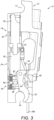
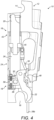
- the first locking member 20 is moveable between a locked position, which is shown in Figure 1 , and an unlocked position, which is shown in Figures 2 to 4 .
- the second locking member 22 is moveable between a locked position, which is shown in Figures 1 to 3 , and an unlocked position, which is shown in Figure 4 .
- a first attachment pin of a working implement (not shown) can be locked in the first recess 14 by first receiving the first attachment pin in the first recess 14 with the first locking member 20 in the unlocked position, then moving the first locking member 20 to the locked position. With the first attachment pin locked in the first recess 14 as described, the first locking pin is prevented from separating from the coupler body 12, and is thus connected to the coupler body 12. The first attachment pin can be unlocked from the first recess 14 by moving the first locking member 20 from the locked position to the unlocked position, enabling the first attachment pin to be removed from the first recess 14.
- a second attachment pin of a working implement can be locked in the second recess 16 by first receiving the second attachment pin in the second recess 16 with the second locking member 22 in the unlocked position, then moving the second locking member 22 to the locked position. With the second attachment pin locked in the second recess 16 as described, the second locking pin is prevented from separating from the coupler body 12, and is thus connected to the coupler body 12. The second attachment pin is then unlocked from the second recess 16 by moving the second locking member 22 from the locked position to the unlocked position, enabling the second attachment pin to be removed from the second recess 16.
- the quick coupler 10 includes an actuator 24 configured to move the first locking member 20 between the locked and unlocked positions.
- the actuator 24 is configured to move the second locking member 22 between the locked and unlocked positions.
- the actuator 24 is located within a cavity 11 in the coupler body 12.
- the actuator 24 is interposed between the first recess 14 and the second recess 16.
- the actuator 24 is a linear hydraulic actuator.
- the actuator 24 includes an actuator body 26, a first piston 28, and a second piston 30 (shown in phantom in Figures 1 to 4 ).
- the actuator 24 is configured to selectively extend and retract the first piston 28 relative to the actuator body 26.
- the actuator 24 is configured to selectively extend and retract the second piston 30 relative to the actuator body 26.
- the actuator 24 may be an electronic or pneumatic actuator.
- the actuator 24 is directly attached to the first locking member 20 (i.e. via the first piston 28). A distal end of the first piston 28 is directly attached to the first locking member 20, e.g. via welding, a fastener or any other suitable means.
- the actuator 24 is indirectly attached to the second locking member 22 (i.e. via the second piston 30).
- the actuator 24 is not directly connected to the coupler body 12. Put another way, the first and second ends of the actuator 24 are moveable relative to the coupler body 12.This enables the actuator 24 to 'float' within the coupler body 12.
- the first locking member 20 has an elongate body extending along a longitudinal axis 34 (represented as a dashed line in Figure 1 ). Put another way, the first locking member 20 may be considered to be a locking rod or pin.
- the first locking member 20 is received in a bore 32 defined in the coupler body 12.
- the first locking member 20 and the bore 32 have corresponding profiles such that movement of the first locking member 20 relative to the coupler body 12 is constrained to the longitudinal axis 34 of the first locking member 20.
- the actuator 24 is configured to move the first locking member 20 from the locked position to the unlocked position by retracting the first piston 28 relative to the actuator body 26 (i.e. along an axis parallel to the longitudinal axis 24). This results in substantially linear movement of the first locking member 20 from the locked position to the unlocked position.
- the first piston 28 i.e. the distal end thereof
- the coupler body 12 i.e. within the bore 32.
- the actuator 24 is configured to move the first locking member 20 from the unlocked position to the locked position by extending the first piston 28 relative to the actuator body 26 (i.e. along an axis parallel to the longitudinal axis 24). This results in substantially linear movement of the first locking member 20 from the unlocked position to the locked position.
- the first piston 28 i.e. the distal end thereof protrudes from the coupler body 12 and delimits the first recess 14.
- the quick coupler 10 includes an indicator arrangement 36, which is configured to indicate when at least one of the first and second locking members is in the unlocked position.
- the indicator arrangement 36 is configured to indicate when the first locking member 20 is in the unlocked position.
- the indicator arrangement 36 includes an indicator member 38.
- the indicator member 38 is attached to the first locking member 20, e.g. via a connector or fastener 40.
- the indicator member 38 is directly connected to the first locking member 20.
- the connector 40 is annular and is fixed, e.g. via an interference fit and/or via welding, around a proximal portion 20a of the first locking member 20 proximate the first piston 28.
- the indicator member 38 may be fixed to the connector 40 via a mechanical fastener.
- the indicator member 38 may be directly attached to the first locking member 20. It will also be appreciated that any suitable configuration of indicator arrangement may be provided, or that the indicator arrangement may be omitted.
- the indicator member 38 is an elongate rod.
- the indicator member 38 has a proximal end 38a attached to the first locking member 38 and a distal end 38b.
- the indicator member 38 extends through a bore (not shown) in the coupler body 12.
- the indicator member 38 is within the coupler body 12.
- the distal end 38b of the indicator member 38 is within the coupler body 12, when the first locking member 20 is in the locked position. Movement of the first locking member 20 moves from the locked to the unlocked position moves the indicator member 38 so as to protrude from the coupler body 12.
- the first locking member 20 is biased into the locked position via a first biasing arrangement 42.
- the first biasing arrangement 42 is configured to move (i.e. bias) the first locking member 20 to the locked position.
- the actuator 24 is required to overcome the first biasing arrangement 42 to move the first locking member 20 from the locked position to the unlocked position.
- the first biasing arrangement 42 may be configured to additionally or alternatively bias the second locking member 22 into the locked position. For example, via a torsion spring. In such embodiments, the actuator 24 would need to overcome the first biasing arrangement 42 to move the second locking member 22 from the locked position to the unlocked position.
- the first biasing arrangement 42 includes a biasing element 44 configured to bias the first locking member 20 in the locked position.
- the biasing element is positioned between the coupler body 12 and the first locking member 20.
- a first end 44a of the biasing element 44 engages the coupler body 12 and a second end 44b of the biasing element 44 engages the first locking member 20.
- the biasing element 44 may be a resilient element such as a spring, but in alternative embodiments any suitable the biasing element or arrangement may be used.
- the first locking member 20 will move from the unlocked position to the locked position under the action of the biasing force.
- the second locking member 22 is pivotally connected to the coupler body 12, e.g. via a first pin 46.
- the second locking member 22 is pivotally mounted to the coupler body 12 such that the locked position defines a rest or default position of the second locking member 22.
- the second locking member 22 is pivotally mounted to the coupler body 12 such that the second locking member 22 is urged under gravity into the locked position.
- the actuator 24 is configured to pivot the second locking member 22 relative to the coupler body 12 from the locked position to the unlocked positions.
- the locking arrangement includes a locking part 48.
- the locking part is moveable between a first position, in which the locking part 48 prevents the second locking member 22 moving from the locked to the unlocked position and a second position, in which movement of the second locking member 22 from the locked position to the unlocked position is permitted.
- the locking part 48 is in the first position.
- Figures 1 and 2 illustrate a first condition of the locking arrangement 18, in which movement of the second locking member 22 from the locked position to the unlocked position is prevented.
- Figures 3 and 4 illustrate a second condition of the locking arrangement 18, in which movement of the second locking member 22 from the locked position to the unlocked position is permitted.
- the locking arrangement 18 may be configured such that in the first condition thereof or in an alternative condition thereof, movement of the first locking member 20 from the locked position to the unlocked position is prevented, and in the second condition thereof, or in an alternative condition thereof, movement of the first locking member 20 from the locked position to the unlocked position is permitted.
- the locking arrangement 18 may include a locking mechanism configured to selectively lock and unlock the first locking member 20 with respect to the connector body 12. Such a locking mechanism may be actuated by the actuator 24 or a separate actuator device.
- the locking part 48 In the first position of the locking part 48, the locking part 48 abuts against an abutment surface 50 of the second locking member 22 to lock the second locking member 22. Abutment between the locking part 48 and the abutment surface 50 prevents the second locking member 22 moving from the locked position to the unlocked position.
- the abutment surface 50 is defined on an angled protrusion 52 formed on the second locking member 22.
- the abutment surface 50 is proximate an apex of the angled protrusion 52.
- the abutment surface 50 may be formed on any suitably shaped portion of the second locking member 22.
- Abutment between a distal portion 49 of the locking part 48 and a proximal portion 51 of the second locking member 22 limits pivoting movement of the second locking member 22 in the locked position.
- the distal portion 49 is in abutment with the proximal portion 51 when the second locking member 22 is in the locked position.
- the locking part 48 In the second position of the locking part 48, which is illustrated in Figure 3 , the locking part 48 is spaced from the abutment surface 50 of the second locking member 22. Hence, the locking part 48 does not abut against the abutment surface 50. As such, movement of the second locking member 22 from the locked position to the unlocked position is permitted.
- the locking part 48 includes a chamfered edge 54. As illustrated in Figure 3 , the chamfered edge 54 is adjacent the apex of the angled protrusion 52 when the locking part 48 is in the second position. It will be appreciated that when pivoting the second locking member 22 anti-clockwise in Figure 3 , the apex of the angled protrusion 52 would abut against the chamfered edge 54 and push the locking part 48 away from the second recess 16 (to the left in Figure 3 ), to permit the second locking member 22 to pivot to the unlocked position.
- the locking arrangement 18 includes an elongate member 56.
- the actuator 24 is configured to move the locking part 48 between the first and the second positions via the elongate member 56.
- a first end of the elongate member 56 is pivotally attached to the coupler body 12, e.g. via a second pin 58.
- a second, distal, end of the elongate member 56 is connected to the locking part 48, e.g. via a third pin 60.
- the actuator 24 is pivotally attached to the elongate member 56, e.g. via a fourth pin 62.
- the actuator 24 is configured to move the locking part 48 from the first to the second position. Retraction of the second piston 30 with respect to the actuator body 26 moves the locking part 48 from the first to the second position. As the second piston 30 retracts, the elongate member 56 pivots about its first end relative to the coupler body (anti-clockwise in the view shown in Figures 1 to 4 ). As the elongate member 56 pivots, the locking part 48 moves substantially linearly from the first position to the second position. The actuator 24 is configured to move the locking part 28 from the second to the first position by reversing the foregoing process.
- the first end of the elongate member 56 is slideably mounted to the coupler body 12. Put another way, the first end of the elongate member 56 can slide, i.e. translate, relative to the coupler body 12 between a first, i.e. rest, position (illustrated in Figures 1 to 3 ) and a second position (illustrated in Figure 4 ).
- the first end of the elongate member 56 is mounted on a guide rail 66, and is slideable along the guide rail 66.
- the guide rail 66 is mounted to the coupler body 12.
- the second pin 58 is biased into the rest position via a second biasing arrangement 68.
- the second biasing arrangement 68 includes a first spring 70a and a second spring 70b, both received on the guide rail 66.
- the second pin 58 is interposed between the two springs 70a, 70b.
- the springs 70a, 70b are arranged such that the spring forces imparted by the springs 70a, 70b are substantially equal when the second pin 58 is in the rest position.
- the actuator 24 is configured to move the second locking member 22 from the locked position (illustrated in Figure 3 ) to the unlocked position (illustrated in Figure 4 ) by moving the locking part 48 from the second position (illustrated in Figure 3 ) to a third position (illustrated in Figure 4 ).
- the actuator 24 is configured to move the locking part 48 from the second position to the third position by retracting the second piston 30 relative to the actuator body 26.
- the elongate member 56 is prevented from pivoting relative to the connector body 12 further due to abutment between the locking part 48 and the constraining surface 64 of the connector body 12.
- the elongate body 56 and the locking part 48 are both constrained to slide relative to the connector body 12 via the second pin 58 and the guide rail 66 in a direction towards the actuator body 26.
- the first spring 70a is compressed.
- the actuator 24 must overcome this spring force to move the locking part 48 from the second position to the third position via the elongate member 56.
- the locking part 48 abuts against of the second locking member 22 (i.e. against an engagement surface 72 of the second locking member 22). In this way, the locking part 48 applies a force to pivot the second locking member 22 from the locked position to the unlocked position.
- the second locking member 22 is in the unlocked position when the locking part 48 reaches the third position.
- the actuator 24 moves the locking part 48 from the third position to the second position by reversing the foregoing process.
- the actuator 24 To retain the locking part 48 in the third position, the actuator 24 must overcome the spring force acting on the second pin 58 via the first spring 70a. As such, when the actuator 24 ceases to apply a force to the elongate member 56 when the locking part 48 is in the third position, for example due to loss of power to the actuator 24 or failure of the actuator 24, the second pin 58 will return to the rest position, which will slide the elongate member 56 away from the actuator body 26, to move the locking part 48 to the second position.
- the locking part 48 will move away from the engagement surface 72 of the second locking member 22 until the locking part 48 applies no force to the engagement surface 72, resulting in the second locking member 22 moving from the unlocked position to the locked position.
- the first locking member 20 and the second locking member 22 are in the locked positions, as illustrated in Figure 1 .
- the locking part 48 is in the first position.
- 'default state' it is meant a state of the quick coupler 10 when the actuator 24 applies no forces to the first locking member 20 and the second locking member 22.
- the actuator 24 is configured to perform the following steps.
- the actuator 24 moves the first locking member 20 from the locked position illustrated in Figure 1 , to the unlocked position shown in Figure 2 . This is effected by retracting the first piston 28 relative to the actuator body 26. During this movement, the locking part 48 remains in the first position such that the second locking member 22 is prevented from moving from the locked position to the unlocked position.
- the actuator 24 moves the locking part 48 from the first position illustrated in Figures 1 and 2 , to the second position illustrated in Figure 3 .
- the second locking member 22 is permitted or enabled to move from the locked position to the unlocked position.
- Further actuation of the actuator 24 moves the second locking member 22 from the locked position, shown in Figures 1 to 3 , to the unlocked position, shown in Figure 4 .
- This movement is effected by moving the locking part 48 from the second position illustrated in Figure 3 to the third position shown in Figure 4 .
- the actuator 24 moves the locking part 48 from the third position illustrated in Figure 4 to the second position illustrated in Figure 3 , to pivot the second locking member 22 from the unlocked position to the locked position.
- the actuator 24 then moves the locking part 48 from the second position illustrated in Figure 3 to the first position illustrated in Figures 1 and 2 , to prevent the second locking member 22 from moving from the locked position to the unlocked position.
- the actuator 24 moves the first locking member 20 from the unlocked position illustrated in Figures 2 to 4 , to the locked position illustrated in Figure 1 .
- a coupling device is illustrated and is indicated generally at 100.
- the coupling device 100 is connectable to a working arm of a working machine (not shown) so as to connect a working implement (not shown) to the working machine.
- the coupling device 100 is configured to tilt and rotate a working implement attached thereto. Put another way, the coupling device 100 is a tiltrotator 100.
- the coupling device 100 includes a first coupler body 102.
- the first coupler body 102 is integrally formed, e.g. integrally cast, as a unitary component. It will be appreciated that in alternative arrangements, the first coupler body 102 may be fabricated, forged, or may be formed from any suitable manufacturing method.
- the first coupler body 102 is pivotally connectable to a working arm so as to be pivotable about a pivot axis X.
- the pivot axis X is a lateral axis or horizontal axis. Put another way, the pivot axis X is a substantially transverse axis of the working machine to which the coupling device 100 is mounted. When the coupling device 100 is connected to a working machine, the pivot axis X is substantially parallel to a rotational axis between the working arm and the body of the working machine.
- the first coupler body 102 includes an arm mounting arrangement 148 for pivotally mounting the first coupler body 102 to a working arm of a working machine.
- the arm mounting arrangement 148 includes first and second arm mounts.
- the first and second arm mounts are provided in the form of two pairs of opposing pivot pin holes configured to receive first and second pivot pins 150, 152, respectively, therethrough to mount the coupling device 100 to a working arm.
- the first pivot pin 150 pivotally mounts the coupling device 100 to the working arm.
- the first pivot pin 150 extends along the pivot axis X.
- the second pivot pin 152 mounts a linkage arm connected to an actuator configured to pivot the coupling device 100 about the pivot axis X.
- the coupling device 100 may not be pivotally mounted to the working arm, and the arm mounting arrangement 148 may fixedly mount the coupling device 100 to the working arm.
- the coupling device 100 includes a second coupler body 104.
- the second coupler body 104 is integrally formed, e.g. integrally cast, as a unitary component. It will be appreciated that in alternative arrangements, the second coupler body 104 may be fabricated, forged, or may be formed from any suitable manufacturing method.
- the second coupler body 104 is pivotally mounted to the first coupler body 102.
- the second coupler body 104 is pivotable relative to first coupler body 102 about a first axis Y. Pivotally mounting the second coupler body 104 to the first coupler body 102 enables the second coupler body 104 to tilt about the first axis Y. Put another way, the first axis Y is a tilt axis.
- the first axis Y is arranged at an angle (i.e. a non-zero angle) relative to the pivot axis X.
- the first axis Y is substantially perpendicular to the pivot axis X.
- the first axis Y is a substantially fore-aft axis.
- the first coupler body 102 and the second coupler body 104 are pivotally connected by two spaced apart tilt pins 106 extending along the first axis Y.
- the coupling device 100 includes the quick coupler 10, which is rotatably mounted to the second coupler body 104 via the slew connector 13.
- the quick coupler 10 is rotatable relative to second coupling body 104 about a second axis Z.
- the second axis Z is arranged at an angle (i.e. a non-zero angle) relative to the first axis Y and to the pivot axis X.
- the second axis Z is arranged substantially perpendicular to the first axis Y and substantially perpendicular to the pivot axis X.
- the second axis Z is a substantially upright axis. Put another way, the second axis Z is a vertical axis.
- the quick coupler 10 is rotatably mounted to the second coupler body 104 via a slewing arrangement.
- the slewing arrangement comprises a worm gear (not shown).
- the coupling device 100 includes a device drive arrangement 120 configured to rotate the quick coupler 10 relative to the second coupler body 104. Put another way, the device drive arrangement 120 drives the slewing arrangement.
- the device drive arrangement 120 is interposed between the first and second tilt pins 106.
- the device drive arrangement 120 is provided in the form of a hydraulic motor 120 configured to drive the slewing arrangement.
- the hydraulic motor 120 is mounted to the second coupler body 104.
- First and second actuators 124 are positioned on an opposing side of the second coupler body 104 to the hydraulic motor 120. Put another way, the first and second actuators 124 are positioned at the first end of the coupling device 100 and the drive arrangement 120 is positioned at the second end of the coupling device 100.
- the coupling device 100 includes a hydraulic manifold 126.
- the hydraulic manifold 126 directs the flow of hydraulic fluid within the coupling device 100.
- the hydraulic manifold 126 selectively provides hydraulic fluid to the drive arrangement 120 to drive the slewing arrangement. Put another way, the hydraulic manifold 126 selectively provides hydraulic fluid to the drive arrangement 120 to rotate the quick coupler 10 relative to the second coupler body 104.
- the first and second spaced apart actuators 124 are configured to tilt the second coupler body 104 relative to the first coupler body 102 about the first axis Y.
- the coupling device 100 includes a first end and a second end, and the first and second actuators 124 are arranged on the first end.
- the first end is arranged distal to the working arm and the second end is arranged proximate to the working arm.
- the first end is a front end of the coupling device 100.
- the first and second actuators 124 are arranged side-by-side on the coupling device 100. Put another way, the first and second actuators 124 are arranged adjacent to each other on the coupling device 100.
- the second coupler body 104 defines a width in a direction perpendicular to an axis extending between the first and second ends.
- the first and second actuators 124 are arranged to be narrower than the width of the second coupling body 104.
- the first and second actuators 124 are arranged so as to be substantially parallel to each other. Put another way, each of the first and second actuators 124 define an elongate axis, and the two elongate axes are substantially parallel. In alternative arrangements, the first and second actuators 124 may be arranged at an angle relative to each other.
- the first and second actuators 124 are arranged so as to be equally spaced apart from a central axis of the coupling device 100. In the embodiment, the first and second actuators 124 are arranged on a side of the coupling device 100 that is remote from the working arm, in use.
- the first and second actuators 124 are pivotally connected to the second coupler body 104 at first 128 and second 130 connection points, respectively.
- the first and second connection points 128, 130 are equally spaced apart from the first axis Y. In the embodiment, the first and second connection points 128, 130 and the first axis Y are arranged so as to define a substantially equilateral triangle.
- the second coupler body 104 includes a projection 134 defining third 136 and fourth 138 recesses on opposing sides thereof.
- the projection 134 is positioned on a side of coupling device 100 remote from a working arm of a working machine, when the coupling device 100 is mounted to a working arm.
- the projection 134 extends in a direction away from a working arm of a working machine, when the coupling device 100 is mounted to a working arm.
- the recesses 136, 138 define the first and second connection points 128, 130.
- the recesses 136, 138 each include a pair of opposing apertures configured to receive a pin (not shown) therein so as to pivotally mount the first and second actuators 124 to the second coupler body 104.
- the pins define the first and second connection points 128, 130.
- the first pivot pin 150 is received in the pair of spaced apart apertures of the first arm mount.
- the first pivot pin 150 i.e. the first arm mount
- the second pivot pin 152 is received in the pair of spaced apart apertures of the second arm mount.
- the spaced apart apertures of the second arm mount define an axis extending therebetween that intersects the second axis Z. Put another way, the second pivot pin 152 extends along an axis that intersects the second axis Z.
- the working machine 200 may be considered to be an excavator.
- the working machine 200 could be any type of working machine such as an excavator having any operating weight, a loader, a telehandler etc.
- Such working machines may be denoted as off-highway vehicles.
- the ground engaging propulsion structure includes a first, or front, axle A1 and a second, or rear, axle A2, each axle being coupled to a pair of wheels 262, 264.
- the ground engaging propulsion structure may include a pair of endless tracks.
- One or both of the axles A1, A2 may be coupled to a drive arrangement (not shown) configured to drive movement of the ground engaging propulsion structure (i.e. the axles A1, A2).
- the drive arrangement causes movement of the working machine 200 over a ground surface.
- the drive arrangement includes a primer mover and a transmission.
- the prime mover may be an internal combustion engine, an electric motor, or may be a hybrid comprising both an internal combustion engine, an electric motor.
- the working machine 200 has a body 266 supported on the ground engaging propulsion arrangement.
- the body 266 of the working machine 200 includes an undercarriage 268 supported on the ground engaging propulsion arrangement.
- a superstructure 270 is connected to the undercarriage 268.
- the superstructure 270 is connected to the undercarriage 268 by a mounting arrangement 272.
- the mounting arrangement 272 is a slewing mechanism in the form of a slewing ring.
- the mounting arrangement 272 permits unrestricted rotation of the superstructure 270 relative to the undercarriage 268 in this embodiment. In alternative arrangements it will be appreciated that the superstructure 270 may not be able to rotate relative to the undercarriage 268.
- a cab 274 from which an operator can operate the working machine 200 is mounted to the superstructure 270.
- the cab 274 includes an operator seat (not shown). It will be appreciated that in some arrangements, the working machine 200 may not include a cab 274 and the operator seat may be directly mounted on the body 266 of the working machine 200.
- the working machine 200 includes a working arm 276.
- the working arm 276 is connected to the body 266 and is provided for performing working operations.
- the working arm 276 is connected to the body 266.
- the working arm 276 is connected to the superstructure 270.
- the working machine 260 includes a counterweight 278 having a mass for counterbalancing the working arm 276.
- the counterweight 278 is provided on the superstructure 270. In alternative arrangements, it will be appreciated that the counterweight may be omitted.
- the coupling device 100 is mounted to the working arm 276.
- the working arm 276 connects to the arm mounting arrangement 148 of the coupling device 100.
- the first pivot pin 150 pivotally mounts the coupling device 100 to the working arm 276.
- the second pivot pin 152 mounts a linkage arm 280 connected to an actuator 282 configured to pivot the coupling device 100 about the pivot axis X.
- the quick coupler 10 may be connected directly to the working arm 276 of the working machine 200.
- the quick coupler 10 may be connected to the working arm 276 via an alternative coupling device.
Landscapes
- Engineering & Computer Science (AREA)
- Mechanical Engineering (AREA)
- Mining & Mineral Resources (AREA)
- Civil Engineering (AREA)
- General Engineering & Computer Science (AREA)
- Structural Engineering (AREA)
- Agricultural Machines (AREA)
- Quick-Acting Or Multi-Walled Pipe Joints (AREA)
Abstract
A quick coupler for connecting a working implement to a working arm of a working machine. The quick coupler comprises: a coupler body comprising first and second recesses configured and arranged for receiving first and second attachment pins of a working implement therein, respectively; a locking arrangement comprising first and second locking members moveable between locked and unlocked positions for locking and unlocking first and second attachment pins in the first and second recesses, respectively; and an actuator configured to move the first and second locking members between the locked and unlocked positions. The quick coupler is configured such that at least one of the first and second locking members are biased into the locked position via a biasing arrangement. The actuator is configured to overcome the biasing arrangement to move the first and/or second locking member from the locked position to the unlocked position.
Description
- The present teachings relate to a quick coupler, a coupling device comprising a quick coupler, and a working machine comprising a quick coupler or a coupling device attached thereto.
- Working machines, also known as off-highway vehicles, typically have a working arm pivotally mounted to the body of the machine, and a working implement, such as a bucket or a grabber, attached to the end of the arm via a coupling device. Attachment of the working implement enables the working machine to perform working operations.
- It is common for such coupling devices to include a quick coupler to connect a variety of working implements to the working arm. Quick couplers tend to include an actuator-operated locking mechanism, which is capable of selectively locking and unlocking two attachment pins of a working implement with respect to the quick coupler, to enable the working implement to be connected to and disconnected from the quick coupler respectively. A problem with such quick couplers is that when the actuator loses power or fails, one or both attachment pins may become unintentionally unlocked from the quick coupler, resulting in potential injury to bystanders if the working implement detaches from the working arm.
- The present teachings seek to overcome or at least mitigate one or more problems associated with the prior art.
- According to a first aspect, there is provided a quick coupler for connecting a working implement to a working arm of a working machine, the quick coupler comprising: a coupler body comprising first and second recesses configured and arranged for receiving first and second attachment pins of a working implement therein, respectively; a locking arrangement comprising first and second locking members moveable between locked and unlocked positions for locking first and second attachment pins in the first and second recesses, respectively; an actuator configured to move the first and second locking members between the locked and unlocked positions; and a first biasing arrangement configured such that at least one of the first and second locking members is biased into the locked position, wherein the actuator is configured to overcome the biasing arrangement to move the first and/or second locking member from the locked position to the unlocked position
- Advantageously, since at least one of the locking members is biased into the locked position, at least one of the locking members defaults to the locked position if the actuator loses power or fails. This may improve safety, for example, by helping to ensure that an attachment pin of a working implement remains locked to the quick coupler in the event that the actuator loses power or fails, such that the working implement cannot detach from the quick coupler in an uncontrolled manner.
- The first biasing arrangement may comprise a biasing element configured to bias the first locking member into the locked position.
- Advantageously, this may help to ensure that the first locking member defaults to the locked position in the event that the actuator loses power or fails.
- The first biasing arrangement may comprise a resilient element such as a spring.
- The second locking member may be pivotally mounted to the coupler body such that the locked position defines a rest or default position of the second locking member, and wherein the actuator may be configured to pivot the second locking member from the locked position to the unlocked position.
- The locking arrangement may comprise a first condition in which movement of the second locking member from the locked position to the unlocked position is prevented and a second condition in which movement of the second locking member from the locked position to the unlocked position is permitted.
- Advantageously, this may prevent unintended unlocking of the locking arrangement.
- The locking arrangement may comprise a locking part moveable between a first position, in which movement of the second locking member from the locked to the unlocked position is prevented, and a second position, in which movement of the second locking member from the locked position to the unlocked position is permitted.
- Advantageously, this may prevent unintended unlocking of the second locking member by controlling movement of a single locking part.
- The actuator may be configured to move the locking part between the first and second positions.
- Advantageously, this enables a single actuator to move the first and second locking members between unlocked and locked positions, and to move the locking member. As such, this helps to minimise the number of actuating components needed to operate the quick coupler.
- The actuator may be configured to move the locking part so as to abut against the second locking member to pivot said second locking member from the locked position to the unlocked position.
- Advantageously, this enables the locking part to both prevent the second locking member from moving away from the locked position, and move the second locking member between unlocked and locked positions. Thus, this may help to minimise the number of movable parts needed in the quick coupler.
- The locking arrangement may comprise an elongate member pivotally attached to the coupler body at a first end thereof, and connected to the locking part at a second, distal, end of the elongate member such that pivoting of the elongate member about the first end moves the locking part between the first and second positions.
- Advantageously, the provision of the elongate member may enable movement of the locking part to be offset from movement of an actuator configured to move the elongate member. This may help to make the quick coupler more compact. Moreover, by pivoting the elongate member, the movement range of the actuator needed to move the locking part between first and second positions may be reduced. This may help to make the quick coupler more compact.
- The first end of the elongate body may be slideably and pivotally mounted to the coupler body.
- This arrangement provides pivotal movement of the elongate body (so as to move the locking part), but also linear sliding movement that enables the locking part to travel substantially linearly between the first and second positions as the elongate member is pivoted.
- The first end of the elongate body may be mounted to the coupler body via a second biasing arrangement.
- This arrangement provides resistance to movement of the first end such that initial movement of the actuator results in pivotal movement of the elongate body (so as to move the locking part), but that above a predetermined force the biasing arrangement (i.e. a spring) is overcome such that the first end of the elongate body is able to move/slide within the coupler body.
- The actuator may be configured to effect substantially linear movement of the first locking member relative to the coupler body between the locked and unlocked positions.
- The quick coupler may comprise an indicator arrangement configured to indicate when at least one of the first and second locking members is in the unlocked position.
- Advantageously, this may indicate to an operator of the working machine or a person standing near the working machine that the first locking member or the second locking member is in the unlocked position, and therefore to be cautious that the work implement coupled to the working machine may imminently detach therefrom.
- The indicator arrangement may comprise an indicator member connected, e.g. directly connected, to the first locking member such that movement of the first locking member moves the indicator member.
- When the first locking member is in the unlocked position, the indicator member may protrude from the coupler body, and wherein, when the first locking member is in the locked position, the indicator member may be within the coupler body
- Advantageously, this helps to ensure that the indicator member is only visible to a person viewing the exterior of the coupler when the first locking member is in the unlocked position.
- The quick coupler may be configured such that, during movement of the first locking member from the locked position to the unlocked position, the second locking member is prevented from moving from the locked to the unlocked position.
- Advantageously, this arrangement may help to ensure that the second attachment pin of the working implement remains locked to the coupler body when detaching the first coupler pin of the working implement from the quick coupler. This may allow the working implement to be detached from the quick coupler in a controlled manner.
- The locking arrangement may comprise a locking part moveable between a first position, in which the locking part prevents the second locking member moving from the locked to the unlocked position and a second position, in which movement of the second locking member from the locked position to the unlocked position is permitted, and wherein during movement of the first locking member from the locked position to the unlocked position, the locking part is in the first position.
- Advantageously, this may prevent unintended unlocking of the second locking member, for example, when detaching the working implement from the quick coupler. As such, this may improve safety by helping to ensure that the working implement can be detached from the quick coupler in a controlled manner.
- The actuator may comprise first and second ends thereof, and wherein said first and second ends are moveable within the coupler body.
- The first end may be directly attached to the first locking member and the second end is indirectly connected to the second locking member.
- Advantageously, this may enable the actuator to float relative to the coupler body.
- The locking arrangement may comprise a locking part moveable between a first position, in which the locking part prevents the second locking member moving from the locked to the unlocked position and a second position, in which movement of the second locking member from the locked position to the unlocked position is permitted, wherein the locking arrangement comprises an elongate member pivotally attached to the coupler body at a first end thereof, and wherein a second, distal, end of the elongate member is connected to the locking part such that pivoting of the elongate member moves the locking part between the first and second positions, and wherein the second end of the actuator is attached to the elongate member between the first and second ends thereof.
- The actuator may be a linear hydraulic actuator.
- Advantageously, this allows a single linear hydraulic actuator to move the first and second locking members between their respective locking and unlocking positions, which removes the need for additional actuators and moving parts.
- The coupler body may comprise a slew connector for rotatably mounting the quick coupler to a body of a coupling device, e.g. a tiltrotator.
- According to a second aspect there is provided a coupling device for coupling a working implement to a working arm of a working machine, the coupling device comprising: a first coupler body comprising an arm mounting arrangement configured to be connectable to a working arm of a working machine; a second coupler body pivotally mounted to the first coupler body so as to be capable of tilting about a first axis; and a quick coupler according to the first aspect rotatably mounted to the second coupler body.
- The coupling device may be a tiltrotator.
- According to a third aspect, there is provided a working machine comprising: a body; a ground engaging propulsion structure supporting the body; and a working arm mounted to the body, wherein a quick coupler of the first aspect, or a coupling device of the second aspect is mounted to a distal end of the working arm.
- The body may comprise an undercarriage supported by the ground engaging propulsion structure and a superstructure, e.g. a rotatable superstructure, connected to the undercarriage, and wherein the working arm may be mounted to the superstructure.
- Embodiments will now be described with reference to the accompanying drawings, in which:
-
Figures 1 to 4 show a cross-sectional side view of a quick coupler according to an embodiment in different configurations; -
Figure 5 is an isometric view of a coupling device including the quick coupler ofFigures 1 to 4 ; and -
Figure 6 is a side view of a working machine including the coupling device ofFigure 5 . - With reference to
Figures 1 to 4 , a quick coupler is illustrated and is indicated generally at 10. Thequick coupler 10 is connectable to a working arm of a working machine (not shown) so as to connect a working implement (not shown) to the working machine. - The
quick coupler 10 includes acoupler body 12. Thecoupler body 12 is integrally formed, e.g. integrally cast, as a unitary component. It will be appreciated that in alternative arrangements, thecoupler body 12 may be fabricated, forged, or may be formed from any suitable manufacturing method. Thecoupler body 12 includes afirst recess 14 and asecond recess 16. Thefirst recess 14 is arranged to receive a first attachment pin (not shown) of a working implement therein, and thesecond recess 16 is arranged to receive a second attachment pin (not shown) of the working implement therein. Aslew connector 13 is secured to thecoupler body 12 for rotatably mounting thequick coupler 10 to a body of a coupling device (not shown), such as a tiltrotator. - The
quick coupler 10 includes a lockingarrangement 18. The lockingarrangement 18 includes afirst locking member 20 and asecond locking member 22. Thefirst locking member 20 is moveable between a locked position, which is shown inFigure 1 , and an unlocked position, which is shown inFigures 2 to 4 . Thesecond locking member 22 is moveable between a locked position, which is shown inFigures 1 to 3 , and an unlocked position, which is shown inFigure 4 . - A first attachment pin of a working implement (not shown) can be locked in the
first recess 14 by first receiving the first attachment pin in thefirst recess 14 with the first lockingmember 20 in the unlocked position, then moving the first lockingmember 20 to the locked position. With the first attachment pin locked in thefirst recess 14 as described, the first locking pin is prevented from separating from thecoupler body 12, and is thus connected to thecoupler body 12. The first attachment pin can be unlocked from thefirst recess 14 by moving the first lockingmember 20 from the locked position to the unlocked position, enabling the first attachment pin to be removed from thefirst recess 14. - A second attachment pin of a working implement (not shown) can be locked in the
second recess 16 by first receiving the second attachment pin in thesecond recess 16 with thesecond locking member 22 in the unlocked position, then moving thesecond locking member 22 to the locked position. With the second attachment pin locked in thesecond recess 16 as described, the second locking pin is prevented from separating from thecoupler body 12, and is thus connected to thecoupler body 12. The second attachment pin is then unlocked from thesecond recess 16 by moving thesecond locking member 22 from the locked position to the unlocked position, enabling the second attachment pin to be removed from thesecond recess 16. - The
quick coupler 10 includes anactuator 24 configured to move the first lockingmember 20 between the locked and unlocked positions. Theactuator 24 is configured to move thesecond locking member 22 between the locked and unlocked positions. Theactuator 24 is located within acavity 11 in thecoupler body 12. Theactuator 24 is interposed between thefirst recess 14 and thesecond recess 16. - In the illustrated embodiment, the
actuator 24 is a linear hydraulic actuator. Theactuator 24 includes anactuator body 26, afirst piston 28, and a second piston 30 (shown in phantom inFigures 1 to 4 ). Theactuator 24 is configured to selectively extend and retract thefirst piston 28 relative to theactuator body 26. Likewise, theactuator 24 is configured to selectively extend and retract thesecond piston 30 relative to theactuator body 26. In alternative embodiments (not shown), theactuator 24 may be an electronic or pneumatic actuator. - The
actuator 24 is directly attached to the first locking member 20 (i.e. via the first piston 28). A distal end of thefirst piston 28 is directly attached to the first lockingmember 20, e.g. via welding, a fastener or any other suitable means. Theactuator 24 is indirectly attached to the second locking member 22 (i.e. via the second piston 30). Theactuator 24 is not directly connected to thecoupler body 12. Put another way, the first and second ends of theactuator 24 are moveable relative to the coupler body 12.This enables theactuator 24 to 'float' within thecoupler body 12. - In the illustrated embodiment, the first locking
member 20 has an elongate body extending along a longitudinal axis 34 (represented as a dashed line inFigure 1 ). Put another way, the first lockingmember 20 may be considered to be a locking rod or pin. Thefirst locking member 20 is received in abore 32 defined in thecoupler body 12. Thefirst locking member 20 and thebore 32 have corresponding profiles such that movement of the first lockingmember 20 relative to thecoupler body 12 is constrained to thelongitudinal axis 34 of the first lockingmember 20. Theactuator 24 is configured to move the first lockingmember 20 from the locked position to the unlocked position by retracting thefirst piston 28 relative to the actuator body 26 (i.e. along an axis parallel to the longitudinal axis 24). This results in substantially linear movement of the first lockingmember 20 from the locked position to the unlocked position. In the unlocked position, the first piston 28 (i.e. the distal end thereof) is positioned within the coupler body 12 (i.e. within the bore 32). - The
actuator 24 is configured to move the first lockingmember 20 from the unlocked position to the locked position by extending thefirst piston 28 relative to the actuator body 26 (i.e. along an axis parallel to the longitudinal axis 24). This results in substantially linear movement of the first lockingmember 20 from the unlocked position to the locked position. In the locked position, the first piston 28 (i.e. the distal end thereof) protrudes from thecoupler body 12 and delimits thefirst recess 14. - The
quick coupler 10 includes anindicator arrangement 36, which is configured to indicate when at least one of the first and second locking members is in the unlocked position. Theindicator arrangement 36 is configured to indicate when the first lockingmember 20 is in the unlocked position. Theindicator arrangement 36 includes anindicator member 38. Theindicator member 38 is attached to the first lockingmember 20, e.g. via a connector orfastener 40. Theindicator member 38 is directly connected to the first lockingmember 20. In the illustrated embodiment, theconnector 40 is annular and is fixed, e.g. via an interference fit and/or via welding, around aproximal portion 20a of the first lockingmember 20 proximate thefirst piston 28. Theindicator member 38 may be fixed to theconnector 40 via a mechanical fastener. Movement of the first lockingmember 20 relative to thecoupler body 12 moves theindicator member 38 relative to thecoupler body 12. It will be appreciated that in alternative arrangements, theindicator member 38 may be directly attached to the first lockingmember 20. It will also be appreciated that any suitable configuration of indicator arrangement may be provided, or that the indicator arrangement may be omitted. - In the illustrated embodiment, the
indicator member 38 is an elongate rod. Theindicator member 38 has aproximal end 38a attached to the first lockingmember 38 and adistal end 38b. Theindicator member 38 extends through a bore (not shown) in thecoupler body 12. When the first lockingmember 20 is in the locked position, theindicator member 38 is within thecoupler body 12. Put another way, thedistal end 38b of theindicator member 38 is within thecoupler body 12, when the first lockingmember 20 is in the locked position. Movement of the first lockingmember 20 moves from the locked to the unlocked position moves theindicator member 38 so as to protrude from thecoupler body 12. - The
first locking member 20 is biased into the locked position via afirst biasing arrangement 42. When theactuator 24 applies no force to the first lockingmember 20, for example when theactuator 24 loses power or fails, thefirst biasing arrangement 42 is configured to move (i.e. bias) the first lockingmember 20 to the locked position. Theactuator 24 is required to overcome thefirst biasing arrangement 42 to move the first lockingmember 20 from the locked position to the unlocked position. In alternative embodiments (not shown), thefirst biasing arrangement 42 may be configured to additionally or alternatively bias thesecond locking member 22 into the locked position. For example, via a torsion spring. In such embodiments, theactuator 24 would need to overcome thefirst biasing arrangement 42 to move thesecond locking member 22 from the locked position to the unlocked position. - The
first biasing arrangement 42 includes a biasing element 44 configured to bias the first lockingmember 20 in the locked position. The biasing element is positioned between thecoupler body 12 and the first lockingmember 20. Afirst end 44a of the biasing element 44 engages thecoupler body 12 and asecond end 44b of the biasing element 44 engages the first lockingmember 20. The biasing element 44 may be a resilient element such as a spring, but in alternative embodiments any suitable the biasing element or arrangement may be used. When theactuator 24 is not actuated, e.g. in the event that theactuator 24 loses power or fails when the first lockingmember 20 is in the unlocked position, such that theactuator 24 applies no force to the first lockingmember 20, the first lockingmember 20 will move from the unlocked position to the locked position under the action of the biasing force. - The
second locking member 22 is pivotally connected to thecoupler body 12, e.g. via afirst pin 46. Thesecond locking member 22 is pivotally mounted to thecoupler body 12 such that the locked position defines a rest or default position of thesecond locking member 22. Put another way, thesecond locking member 22 is pivotally mounted to thecoupler body 12 such that thesecond locking member 22 is urged under gravity into the locked position. Theactuator 24 is configured to pivot thesecond locking member 22 relative to thecoupler body 12 from the locked position to the unlocked positions. - The locking arrangement includes a locking
part 48. The locking part is moveable between a first position, in which the lockingpart 48 prevents thesecond locking member 22 moving from the locked to the unlocked position and a second position, in which movement of thesecond locking member 22 from the locked position to the unlocked position is permitted. During movement of the first lockingmember 20 from the locked position to the unlocked position, the lockingpart 48 is in the first position.Figures 1 and2 illustrate a first condition of the lockingarrangement 18, in which movement of thesecond locking member 22 from the locked position to the unlocked position is prevented.Figures 3 and4 illustrate a second condition of the lockingarrangement 18, in which movement of thesecond locking member 22 from the locked position to the unlocked position is permitted. - In alternative embodiments (not shown), the locking
arrangement 18 may be configured such that in the first condition thereof or in an alternative condition thereof, movement of the first lockingmember 20 from the locked position to the unlocked position is prevented, and in the second condition thereof, or in an alternative condition thereof, movement of the first lockingmember 20 from the locked position to the unlocked position is permitted. In such embodiments, the lockingarrangement 18 may include a locking mechanism configured to selectively lock and unlock the first lockingmember 20 with respect to theconnector body 12. Such a locking mechanism may be actuated by theactuator 24 or a separate actuator device. - In the first position of the locking
part 48, the lockingpart 48 abuts against anabutment surface 50 of thesecond locking member 22 to lock thesecond locking member 22. Abutment between the lockingpart 48 and theabutment surface 50 prevents thesecond locking member 22 moving from the locked position to the unlocked position. Theabutment surface 50 is defined on anangled protrusion 52 formed on thesecond locking member 22. Theabutment surface 50 is proximate an apex of theangled protrusion 52. In alternative embodiments (not shown), theabutment surface 50 may be formed on any suitably shaped portion of thesecond locking member 22. Abutment between adistal portion 49 of the lockingpart 48 and aproximal portion 51 of thesecond locking member 22 limits pivoting movement of thesecond locking member 22 in the locked position. Thedistal portion 49 is in abutment with theproximal portion 51 when thesecond locking member 22 is in the locked position. - In the second position of the locking
part 48, which is illustrated inFigure 3 , the lockingpart 48 is spaced from theabutment surface 50 of thesecond locking member 22. Hence, the lockingpart 48 does not abut against theabutment surface 50. As such, movement of thesecond locking member 22 from the locked position to the unlocked position is permitted. - The locking
part 48 includes a chamferededge 54. As illustrated inFigure 3 , the chamferededge 54 is adjacent the apex of theangled protrusion 52 when the lockingpart 48 is in the second position. It will be appreciated that when pivoting thesecond locking member 22 anti-clockwise inFigure 3 , the apex of theangled protrusion 52 would abut against the chamferededge 54 and push the lockingpart 48 away from the second recess 16 (to the left inFigure 3 ), to permit thesecond locking member 22 to pivot to the unlocked position. - The locking
arrangement 18 includes anelongate member 56. Theactuator 24 is configured to move the lockingpart 48 between the first and the second positions via theelongate member 56. A first end of theelongate member 56 is pivotally attached to thecoupler body 12, e.g. via asecond pin 58. A second, distal, end of theelongate member 56 is connected to the lockingpart 48, e.g. via athird pin 60. Theactuator 24 is pivotally attached to theelongate member 56, e.g. via afourth pin 62. - The
actuator 24 is configured to move the lockingpart 48 from the first to the second position. Retraction of thesecond piston 30 with respect to theactuator body 26 moves the lockingpart 48 from the first to the second position. As thesecond piston 30 retracts, theelongate member 56 pivots about its first end relative to the coupler body (anti-clockwise in the view shown inFigures 1 to 4 ). As theelongate member 56 pivots, the lockingpart 48 moves substantially linearly from the first position to the second position. Theactuator 24 is configured to move the lockingpart 28 from the second to the first position by reversing the foregoing process. - The first end of the
elongate member 56 is slideably mounted to thecoupler body 12. Put another way, the first end of theelongate member 56 can slide, i.e. translate, relative to thecoupler body 12 between a first, i.e. rest, position (illustrated inFigures 1 to 3 ) and a second position (illustrated inFigure 4 ). The first end of theelongate member 56 is mounted on aguide rail 66, and is slideable along theguide rail 66. Theguide rail 66 is mounted to thecoupler body 12. Thesecond pin 58 is biased into the rest position via asecond biasing arrangement 68. In the illustrated embodiment, thesecond biasing arrangement 68 includes afirst spring 70a and asecond spring 70b, both received on theguide rail 66. Thesecond pin 58 is interposed between the twosprings springs springs second pin 58 is in the rest position. - With reference to
Figures 3 and4 , theactuator 24 is configured to move thesecond locking member 22 from the locked position (illustrated inFigure 3 ) to the unlocked position (illustrated inFigure 4 ) by moving the lockingpart 48 from the second position (illustrated inFigure 3 ) to a third position (illustrated inFigure 4 ). Theactuator 24 is configured to move the lockingpart 48 from the second position to the third position by retracting thesecond piston 30 relative to theactuator body 26. As thesecond piston 30 retracts, theelongate member 56 is prevented from pivoting relative to theconnector body 12 further due to abutment between the lockingpart 48 and the constrainingsurface 64 of theconnector body 12. As such, theelongate body 56 and the lockingpart 48 are both constrained to slide relative to theconnector body 12 via thesecond pin 58 and theguide rail 66 in a direction towards theactuator body 26. - As the first end of the
elongate member 56 slides from the first to the second position, thefirst spring 70a is compressed. As such, theactuator 24 must overcome this spring force to move the lockingpart 48 from the second position to the third position via theelongate member 56. As theelongate body 56 slides towards the second position (i.e. actuatorbody 26, the lockingpart 48 abuts against of the second locking member 22 (i.e. against anengagement surface 72 of the second locking member 22). In this way, the lockingpart 48 applies a force to pivot thesecond locking member 22 from the locked position to the unlocked position. Thesecond locking member 22 is in the unlocked position when the lockingpart 48 reaches the third position. - To move the
second locking member 22 from the unlocked position to the locked position, theactuator 24 moves the lockingpart 48 from the third position to the second position by reversing the foregoing process. - To retain the locking
part 48 in the third position, theactuator 24 must overcome the spring force acting on thesecond pin 58 via thefirst spring 70a. As such, when theactuator 24 ceases to apply a force to theelongate member 56 when the lockingpart 48 is in the third position, for example due to loss of power to theactuator 24 or failure of theactuator 24, thesecond pin 58 will return to the rest position, which will slide theelongate member 56 away from theactuator body 26, to move the lockingpart 48 to the second position. In such an event, as the lockingpart 48 moves from the third position to the second position, the lockingpart 48 will move away from theengagement surface 72 of thesecond locking member 22 until the lockingpart 48 applies no force to theengagement surface 72, resulting in thesecond locking member 22 moving from the unlocked position to the locked position. - In the following, operation of the
quick coupler 10 will be described with reference toFigures 1 to 4 . - In a default state of the
quick coupler 10, the first lockingmember 20 and thesecond locking member 22 are in the locked positions, as illustrated inFigure 1 . Moreover, the lockingpart 48 is in the first position. By 'default state', it is meant a state of thequick coupler 10 when theactuator 24 applies no forces to the first lockingmember 20 and thesecond locking member 22. - To connect a working implement to the
quick coupler 10, or to disconnect a working implement from thequick coupler 10, theactuator 24 is configured to perform the following steps. - Initially, the
actuator 24 moves the first lockingmember 20 from the locked position illustrated inFigure 1 , to the unlocked position shown inFigure 2 . This is effected by retracting thefirst piston 28 relative to theactuator body 26. During this movement, the lockingpart 48 remains in the first position such that thesecond locking member 22 is prevented from moving from the locked position to the unlocked position. - Next, the
actuator 24 moves the lockingpart 48 from the first position illustrated inFigures 1 and2 , to the second position illustrated inFigure 3 . As such, thesecond locking member 22 is permitted or enabled to move from the locked position to the unlocked position. Further actuation of theactuator 24 moves thesecond locking member 22 from the locked position, shown inFigures 1 to 3 , to the unlocked position, shown inFigure 4 . This movement is effected by moving the lockingpart 48 from the second position illustrated inFigure 3 to the third position shown inFigure 4 . - When actuation of the
actuator 24 is stopped, theactuator 24 moves the lockingpart 48 from the third position illustrated inFigure 4 to the second position illustrated inFigure 3 , to pivot thesecond locking member 22 from the unlocked position to the locked position. Theactuator 24 then moves the lockingpart 48 from the second position illustrated inFigure 3 to the first position illustrated inFigures 1 and2 , to prevent thesecond locking member 22 from moving from the locked position to the unlocked position. Subsequently, theactuator 24 moves the first lockingmember 20 from the unlocked position illustrated inFigures 2 to 4 , to the locked position illustrated inFigure 1 . - With reference to
Figure 5 , a coupling device is illustrated and is indicated generally at 100. Thecoupling device 100 is connectable to a working arm of a working machine (not shown) so as to connect a working implement (not shown) to the working machine. Thecoupling device 100 is configured to tilt and rotate a working implement attached thereto. Put another way, thecoupling device 100 is atiltrotator 100. - The
coupling device 100 includes afirst coupler body 102. Thefirst coupler body 102 is integrally formed, e.g. integrally cast, as a unitary component. It will be appreciated that in alternative arrangements, thefirst coupler body 102 may be fabricated, forged, or may be formed from any suitable manufacturing method. Thefirst coupler body 102 is pivotally connectable to a working arm so as to be pivotable about a pivot axis X. The pivot axis X is a lateral axis or horizontal axis. Put another way, the pivot axis X is a substantially transverse axis of the working machine to which thecoupling device 100 is mounted. When thecoupling device 100 is connected to a working machine, the pivot axis X is substantially parallel to a rotational axis between the working arm and the body of the working machine. - The
first coupler body 102 includes anarm mounting arrangement 148 for pivotally mounting thefirst coupler body 102 to a working arm of a working machine. Thearm mounting arrangement 148 includes first and second arm mounts. The first and second arm mounts are provided in the form of two pairs of opposing pivot pin holes configured to receive first and second pivot pins 150, 152, respectively, therethrough to mount thecoupling device 100 to a working arm. - The
first pivot pin 150 pivotally mounts thecoupling device 100 to the working arm. Thefirst pivot pin 150 extends along the pivot axis X. In the embodiment, thesecond pivot pin 152 mounts a linkage arm connected to an actuator configured to pivot thecoupling device 100 about the pivot axis X. In some alternative arrangements, however, thecoupling device 100 may not be pivotally mounted to the working arm, and thearm mounting arrangement 148 may fixedly mount thecoupling device 100 to the working arm. - The
coupling device 100 includes asecond coupler body 104. Thesecond coupler body 104 is integrally formed, e.g. integrally cast, as a unitary component. It will be appreciated that in alternative arrangements, thesecond coupler body 104 may be fabricated, forged, or may be formed from any suitable manufacturing method. Thesecond coupler body 104 is pivotally mounted to thefirst coupler body 102. Thesecond coupler body 104 is pivotable relative tofirst coupler body 102 about a first axis Y. Pivotally mounting thesecond coupler body 104 to thefirst coupler body 102 enables thesecond coupler body 104 to tilt about the first axis Y. Put another way, the first axis Y is a tilt axis. - The first axis Y is arranged at an angle (i.e. a non-zero angle) relative to the pivot axis X. In the illustrated arrangement, the first axis Y is substantially perpendicular to the pivot axis X. The first axis Y is a substantially fore-aft axis. The
first coupler body 102 and thesecond coupler body 104 are pivotally connected by two spaced apart tilt pins 106 extending along the first axis Y. - The
coupling device 100 includes thequick coupler 10, which is rotatably mounted to thesecond coupler body 104 via theslew connector 13. Thequick coupler 10 is rotatable relative tosecond coupling body 104 about a second axis Z. The second axis Z is arranged at an angle (i.e. a non-zero angle) relative to the first axis Y and to the pivot axis X. In the arrangement shown, the second axis Z is arranged substantially perpendicular to the first axis Y and substantially perpendicular to the pivot axis X. The second axis Z is a substantially upright axis. Put another way, the second axis Z is a vertical axis. - The
quick coupler 10 is rotatably mounted to thesecond coupler body 104 via a slewing arrangement. In the embodiment, the slewing arrangement comprises a worm gear (not shown). Thecoupling device 100 includes adevice drive arrangement 120 configured to rotate thequick coupler 10 relative to thesecond coupler body 104. Put another way, thedevice drive arrangement 120 drives the slewing arrangement. Thedevice drive arrangement 120 is interposed between the first and second tilt pins 106. Thedevice drive arrangement 120 is provided in the form of ahydraulic motor 120 configured to drive the slewing arrangement. Thehydraulic motor 120 is mounted to thesecond coupler body 104. First andsecond actuators 124 are positioned on an opposing side of thesecond coupler body 104 to thehydraulic motor 120. Put another way, the first andsecond actuators 124 are positioned at the first end of thecoupling device 100 and thedrive arrangement 120 is positioned at the second end of thecoupling device 100. - The
coupling device 100 includes ahydraulic manifold 126. Thehydraulic manifold 126 directs the flow of hydraulic fluid within thecoupling device 100. Thehydraulic manifold 126 selectively provides hydraulic fluid to thedrive arrangement 120 to drive the slewing arrangement. Put another way, thehydraulic manifold 126 selectively provides hydraulic fluid to thedrive arrangement 120 to rotate thequick coupler 10 relative to thesecond coupler body 104. - The first and second spaced apart actuators 124 are configured to tilt the
second coupler body 104 relative to thefirst coupler body 102 about the first axis Y. Thecoupling device 100 includes a first end and a second end, and the first andsecond actuators 124 are arranged on the first end. When thecoupling device 100 is mounted to a working arm of a working machine, the first end is arranged distal to the working arm and the second end is arranged proximate to the working arm. Put another way, when thecoupling device 100 is mounted to a working arm of a working machine, the first end is a front end of thecoupling device 100. - The first and
second actuators 124 are arranged side-by-side on thecoupling device 100. Put another way, the first andsecond actuators 124 are arranged adjacent to each other on thecoupling device 100. Thesecond coupler body 104 defines a width in a direction perpendicular to an axis extending between the first and second ends. The first andsecond actuators 124 are arranged to be narrower than the width of thesecond coupling body 104. - The first and
second actuators 124 are arranged so as to be substantially parallel to each other. Put another way, each of the first andsecond actuators 124 define an elongate axis, and the two elongate axes are substantially parallel. In alternative arrangements, the first andsecond actuators 124 may be arranged at an angle relative to each other. - The first and
second actuators 124 are arranged so as to be equally spaced apart from a central axis of thecoupling device 100. In the embodiment, the first andsecond actuators 124 are arranged on a side of thecoupling device 100 that is remote from the working arm, in use. The first andsecond actuators 124 are pivotally connected to thesecond coupler body 104 at first 128 and second 130 connection points, respectively. The first and second connection points 128, 130 are equally spaced apart from the first axis Y. In the embodiment, the first and second connection points 128, 130 and the first axis Y are arranged so as to define a substantially equilateral triangle. - The
second coupler body 104 includes aprojection 134 defining third 136 and fourth 138 recesses on opposing sides thereof. Theprojection 134 is positioned on a side ofcoupling device 100 remote from a working arm of a working machine, when thecoupling device 100 is mounted to a working arm. Theprojection 134 extends in a direction away from a working arm of a working machine, when thecoupling device 100 is mounted to a working arm. Therecesses recesses second actuators 124 to thesecond coupler body 104. The pins define the first and second connection points 128, 130. - The
first pivot pin 150 is received in the pair of spaced apart apertures of the first arm mount. The first pivot pin 150 (i.e. the first arm mount) is positioned on an opposing side ofcoupling device 100 to the first andsecond actuators 124. Thesecond pivot pin 152 is received in the pair of spaced apart apertures of the second arm mount. The spaced apart apertures of the second arm mount define an axis extending therebetween that intersects the second axis Z. Put another way, thesecond pivot pin 152 extends along an axis that intersects the second axis Z. - Referring to
Figure 6 , there is illustrated a workingmachine 200. In the present embodiment, the workingmachine 200 may be considered to be an excavator. The workingmachine 200 could be any type of working machine such as an excavator having any operating weight, a loader, a telehandler etc. Such working machines may be denoted as off-highway vehicles. - The ground engaging propulsion structure includes a first, or front, axle A1 and a second, or rear, axle A2, each axle being coupled to a pair of
wheels machine 200 over a ground surface. The drive arrangement includes a primer mover and a transmission. The prime mover may be an internal combustion engine, an electric motor, or may be a hybrid comprising both an internal combustion engine, an electric motor. - The working
machine 200 has a body 266 supported on the ground engaging propulsion arrangement. The body 266 of the workingmachine 200 includes anundercarriage 268 supported on the ground engaging propulsion arrangement. Asuperstructure 270 is connected to theundercarriage 268. Thesuperstructure 270 is connected to theundercarriage 268 by a mountingarrangement 272. - In the arrangement shown, the mounting
arrangement 272 is a slewing mechanism in the form of a slewing ring. The mountingarrangement 272 permits unrestricted rotation of thesuperstructure 270 relative to theundercarriage 268 in this embodiment. In alternative arrangements it will be appreciated that thesuperstructure 270 may not be able to rotate relative to theundercarriage 268. - A
cab 274 from which an operator can operate the workingmachine 200 is mounted to thesuperstructure 270. Thecab 274 includes an operator seat (not shown). It will be appreciated that in some arrangements, the workingmachine 200 may not include acab 274 and the operator seat may be directly mounted on the body 266 of the workingmachine 200. - The working
machine 200 includes a workingarm 276. The workingarm 276 is connected to the body 266 and is provided for performing working operations. The workingarm 276 is connected to the body 266. In the arrangement shown, the workingarm 276 is connected to thesuperstructure 270. The workingmachine 260 includes acounterweight 278 having a mass for counterbalancing the workingarm 276. Thecounterweight 278 is provided on thesuperstructure 270. In alternative arrangements, it will be appreciated that the counterweight may be omitted. - The
coupling device 100 is mounted to the workingarm 276. The workingarm 276 connects to thearm mounting arrangement 148 of thecoupling device 100. Thefirst pivot pin 150 pivotally mounts thecoupling device 100 to the workingarm 276. Thesecond pivot pin 152 mounts alinkage arm 280 connected to anactuator 282 configured to pivot thecoupling device 100 about the pivot axis X. - In alternative embodiments (not shown), the
quick coupler 10 may be connected directly to the workingarm 276 of the workingmachine 200. Alternatively, thequick coupler 10 may be connected to the workingarm 276 via an alternative coupling device. - Although the teachings have been described above with reference to one or more preferred embodiments, it will be appreciated that various changes or modifications may be made without departing from the scope as defined in the appended claims.
Claims (15)
- A quick coupler for connecting a working implement to a working arm of a working machine, the quick coupler comprising:a coupler body comprising first and second recesses configured and arranged for receiving first and second attachment pins of a working implement therein, respectively;a locking arrangement comprising first and second locking members moveable between locked and unlocked positions for locking first and second attachment pins in the first and second recesses, respectively;an actuator configured to move the first and second locking members between the locked and unlocked positions; anda first biasing arrangement configured such that at least one of the first and second locking members is biased into the locked position,wherein the actuator is configured to overcome the biasing arrangement to move the first and/or second locking member from the locked position to the unlocked position.
- The quick coupler of claim 1, wherein the first biasing arrangement comprises a biasing element, e.g. a resilient element such as a spring, configured to bias the first locking member into the locked position.
- The quick coupler of claim 1 or claim 2, wherein the locking arrangement comprises a first condition in which movement of the second locking member from the locked position to the unlocked position is prevented and a second condition in which movement of the second locking member from the locked position to the unlocked position is permitted.
- The quick coupler of claim 3, wherein the locking arrangement comprises a locking part moveable between a first position, in which movement of the second locking member from the locked to the unlocked position is prevented, and a second position, in which movement of the second locking member from the locked position to the unlocked position is permitted.
- The quick coupler of claim 4, wherein the locking arrangement comprises an elongate member pivotally attached to the coupler body at a first end thereof, and connected to the locking part at a second, distal, end of the elongate member such that pivoting of the elongate member about the first end moves the locking part between the first and second positions.
- The quick coupler of claim 5, wherein the first end of the elongate body is slideably and pivotally mounted to the coupler body.
- The quick coupler of claim 6, wherein the first end of the elongate body is mounted to the coupler body via a second biasing arrangement.
- The quick coupler of any preceding claim, wherein the actuator is configured to effect substantially linear movement of the first locking member relative to the coupler body between the locked and unlocked positions.
- The quick coupler of any preceding claim, comprising an indicator arrangement configured to indicate when at least one of the first and second locking members is in the unlocked position.
- The quick coupler of any preceding claim, configured such that, during movement of the first locking member from the locked position to the unlocked position, the second locking member is prevented from moving from the locked to the unlocked position.
- The quick coupler of claim 10, wherein the locking arrangement comprises a locking part moveable between a first position, in which the locking part prevents the second locking member moving from the locked to the unlocked position and a second position, in which movement of the second locking member from the locked position to the unlocked position is permitted, and wherein during movement of the first locking member from the locked position to the unlocked position, the locking part is in the first position.
- The quick coupler of any preceding claim, wherein the actuator comprises first and second ends thereof, and wherein said first and second ends are moveable within the coupler body, optionally wherein the first end is directly attached to the first locking member and the second end is indirectly connected to the second locking member.
- The quick coupler of any preceding claim, wherein the coupler body comprises a slew connector for rotatably mounting the quick coupler to a body of a coupling device, e.g. a tiltrotator.
- A coupling device, optionally a tiltrotator, for coupling a working implement to a working arm of a working machine, the coupling device comprising:a first coupler body comprising an arm mounting arrangement configured to be connectable to a working arm of a working machine;a second coupler body pivotally mounted to the first coupler body so as to be capable of tilting about a first axis; anda quick coupler according to any preceding claim rotatably mounted to the second coupler body.
- A working machine comprising:a body;a ground engaging propulsion structure supporting the body; anda working arm mounted to the body,wherein a quick coupler of any one of claims 1 to 13, or a coupling device of claim 14 is mounted to a distal end of the working arm.
Applications Claiming Priority (1)
| Application Number | Priority Date | Filing Date | Title |
|---|---|---|---|
| GB2203506.7A GB2616614A (en) | 2022-03-14 | 2022-03-14 | A quick coupler |
Publications (1)
| Publication Number | Publication Date |
|---|---|
| EP4245925A1 true EP4245925A1 (en) | 2023-09-20 |
Family
ID=81254845
Family Applications (1)
| Application Number | Title | Priority Date | Filing Date |
|---|---|---|---|
| EP23160495.0A Pending EP4245925A1 (en) | 2022-03-14 | 2023-03-07 | A quick coupler |
Country Status (2)
| Country | Link |
|---|---|
| EP (1) | EP4245925A1 (en) |
| GB (1) | GB2616614A (en) |
Cited By (1)
| Publication number | Priority date | Publication date | Assignee | Title |
|---|---|---|---|---|
| EP4653619A1 (en) * | 2024-05-22 | 2025-11-26 | TM BENNE S.r.l. | Coupling device for construction machinery and its saddle |
Citations (3)
| Publication number | Priority date | Publication date | Assignee | Title |
|---|---|---|---|---|
| GB2479221A (en) * | 2010-03-31 | 2011-10-05 | Ian Hill | Coupler with an actuated latch and a blocking member operated indirectly by the actuators operation |
| US9562346B2 (en) * | 2012-10-08 | 2017-02-07 | Rototilt Group Ab | Apparatus for connecting an appliance/tool and a method therefor |
| WO2018056841A1 (en) * | 2016-09-20 | 2018-03-29 | Bruce Archibald Short | Quick hitch coupler |
Family Cites Families (2)
| Publication number | Priority date | Publication date | Assignee | Title |
|---|---|---|---|---|
| KR101651856B1 (en) * | 2015-03-31 | 2016-09-05 | (주)정우엠텍 | Triple safety device of quick coupler |
| GB2580109A (en) * | 2018-12-21 | 2020-07-15 | Geith International Ltd | A coupler for coupling an attachment to a dipper arm |
-
2022
- 2022-03-14 GB GB2203506.7A patent/GB2616614A/en active Pending
-
2023
- 2023-03-07 EP EP23160495.0A patent/EP4245925A1/en active Pending
Patent Citations (3)
| Publication number | Priority date | Publication date | Assignee | Title |
|---|---|---|---|---|
| GB2479221A (en) * | 2010-03-31 | 2011-10-05 | Ian Hill | Coupler with an actuated latch and a blocking member operated indirectly by the actuators operation |
| US9562346B2 (en) * | 2012-10-08 | 2017-02-07 | Rototilt Group Ab | Apparatus for connecting an appliance/tool and a method therefor |
| WO2018056841A1 (en) * | 2016-09-20 | 2018-03-29 | Bruce Archibald Short | Quick hitch coupler |
Cited By (1)
| Publication number | Priority date | Publication date | Assignee | Title |
|---|---|---|---|---|
| EP4653619A1 (en) * | 2024-05-22 | 2025-11-26 | TM BENNE S.r.l. | Coupling device for construction machinery and its saddle |
Also Published As
| Publication number | Publication date |
|---|---|
| GB202203506D0 (en) | 2022-04-27 |
| GB2616614A (en) | 2023-09-20 |
Similar Documents
| Publication | Publication Date | Title |
|---|---|---|
| CA2927974C (en) | Implement interface | |
| EP1997964B1 (en) | Working machine with a rotatable cab | |
| US20240344293A1 (en) | Loader lift arm | |
| CN107075835B (en) | work vehicle | |
| US9243382B2 (en) | Ripper device for motor grader, and motor grader equipped with this device | |
| US11661720B2 (en) | Attachment system for a work vehicle implement | |
| US12222743B2 (en) | Lever device and working machine | |
| CA2469710C (en) | Tool coupler | |
| GB2616614A (en) | A quick coupler | |
| US6332748B1 (en) | Rotating pawl tool latch | |
| US7937858B2 (en) | Hitch assembly and tractor scraper using same | |
| US8468905B2 (en) | Operating device for control valve | |
| EP3971000B1 (en) | Pick-up hitch assembly | |
| EP3927572B1 (en) | Traction control for steering articulated power machine | |
| IES86256B2 (en) | A safety mechanism for a coupler for coupling an accessory to a dipper arm. | |
| CN112639209A (en) | Lift arm leveling system | |
| EP4053344B1 (en) | A coupling device for a work machine | |
| GB2582595A (en) | Quick coupler for attaching a tool to a hydraulic excavator or other work machine | |
| GB2627790A (en) | A quick coupler | |
| EP4107047A1 (en) | Joystick anti-hitting seat steering mechanism for work machines | |
| US20170191240A1 (en) | Work Tool Coupler Engagement System | |
| CN119122895B (en) | Quick connection device and engineering machinery | |
| KR102572963B1 (en) | mechanically controlled linkages | |
| KR102875532B1 (en) | Loader work apparatus comprising self leveling kit | |
| EP1264938A1 (en) | Earthmoving machine and actuating device for controlling lateral movement of a loading shovel |
Legal Events
| Date | Code | Title | Description |
|---|---|---|---|
| PUAI | Public reference made under article 153(3) epc to a published international application that has entered the european phase |
Free format text: ORIGINAL CODE: 0009012 |
|
| STAA | Information on the status of an ep patent application or granted ep patent |
Free format text: STATUS: REQUEST FOR EXAMINATION WAS MADE |
|
| 17P | Request for examination filed |
Effective date: 20230307 |
|
| AK | Designated contracting states |
Kind code of ref document: A1 Designated state(s): AL AT BE BG CH CY CZ DE DK EE ES FI FR GB GR HR HU IE IS IT LI LT LU LV MC ME MK MT NL NO PL PT RO RS SE SI SK SM TR |
|
| P01 | Opt-out of the competence of the unified patent court (upc) registered |
Free format text: CASE NUMBER: APP_53/2025 Effective date: 20250102 |