EP4245912A2 - Bracket for a pivot rod in a doctor arrangement and doctor arrangement for a fiber web machine - Google Patents
Bracket for a pivot rod in a doctor arrangement and doctor arrangement for a fiber web machine Download PDFInfo
- Publication number
- EP4245912A2 EP4245912A2 EP23160877.9A EP23160877A EP4245912A2 EP 4245912 A2 EP4245912 A2 EP 4245912A2 EP 23160877 A EP23160877 A EP 23160877A EP 4245912 A2 EP4245912 A2 EP 4245912A2
- Authority
- EP
- European Patent Office
- Prior art keywords
- bracket
- doctor
- base
- doctor arrangement
- pivot rod
- Prior art date
- Legal status (The legal status is an assumption and is not a legal conclusion. Google has not performed a legal analysis and makes no representation as to the accuracy of the status listed.)
- Pending
Links
- 239000000835 fiber Substances 0.000 title claims abstract description 11
- 210000005069 ears Anatomy 0.000 claims abstract description 20
- 230000008719 thickening Effects 0.000 claims description 2
- 239000002184 metal Substances 0.000 description 5
- 238000009434 installation Methods 0.000 description 3
- 238000004519 manufacturing process Methods 0.000 description 3
- XLYOFNOQVPJJNP-UHFFFAOYSA-N water Substances O XLYOFNOQVPJJNP-UHFFFAOYSA-N 0.000 description 3
- 230000000694 effects Effects 0.000 description 2
- 239000000463 material Substances 0.000 description 2
- 230000004048 modification Effects 0.000 description 2
- 238000012986 modification Methods 0.000 description 2
- 238000012546 transfer Methods 0.000 description 2
- 239000011800 void material Substances 0.000 description 2
- 238000005452 bending Methods 0.000 description 1
- 238000004140 cleaning Methods 0.000 description 1
- 238000000576 coating method Methods 0.000 description 1
- 230000007797 corrosion Effects 0.000 description 1
- 238000005260 corrosion Methods 0.000 description 1
- 238000005336 cracking Methods 0.000 description 1
- 230000007423 decrease Effects 0.000 description 1
- 238000013461 design Methods 0.000 description 1
- 238000001035 drying Methods 0.000 description 1
- 238000005516 engineering process Methods 0.000 description 1
- 239000011888 foil Substances 0.000 description 1
- 239000012535 impurity Substances 0.000 description 1
- 230000005923 long-lasting effect Effects 0.000 description 1
- 238000012423 maintenance Methods 0.000 description 1
- 229920000642 polymer Polymers 0.000 description 1
- 230000002035 prolonged effect Effects 0.000 description 1
- 230000008439 repair process Effects 0.000 description 1
Images



Classifications
-
- D—TEXTILES; PAPER
- D21—PAPER-MAKING; PRODUCTION OF CELLULOSE
- D21G—CALENDERS; ACCESSORIES FOR PAPER-MAKING MACHINES
- D21G3/00—Doctors
- D21G3/005—Doctor knifes
Definitions
- the invention relates to a bracket for a pivot rod in a doctor arrangement, which bracket has a base with a mounting aperture and adjacent ears with a hole for a pivot rod arranged perpendicular to the base.
- the invention also relates to a doctor arrangement for a fiber web machine.
- US-patent number 5279710 discloses a doctor blade supporting structure for paper making rolls.
- the doctor blade is for cleaning the roll surface of a roll in a fiber web machine. Depending on the position, the doctor blade also removes water or the fiber web itself.
- the roll surface may be smooth, grooved or drilled, for example.
- the supporting structure includes a blade holder which is pivotally fixed to a doctor beam, for example.
- the blade holder includes several parallel loading fingers which are screwed to a top plate.
- the bracket has a base with a mounting aperture and adjacent ears with a hole. While the fingers and brackets are targeted to each other a pivot rod is led though the holes and the loading fingers.
- the blade holder can be pivoted in relation to the doctor beam.
- For pivoting there are loading tubes in connection with the top plate.
- the blade holders position the doctor blade firmly against the roll, accommodate roll surface irregularities, facilitate rapid blade changes, and, within limits, compensate for thermal expansion. Proper doctoring is critical to many industrial processes like fiber web production.
- the known brackets are manufactured from sheet metal. A strip of sheet metal is first stamped and then bent as a U-shape bracket.
- the bracket has also a base with a mounting aperture.
- one mounting bolt supports the bracket.
- one or more brackets will break in the corners, i.e. at the point where the base changes to the ears.
- the stress from the bending of the sheet metal weakens the structural integrity .
- the highest stress points locate at the corners.
- the sheet metal is also too thin and is prone to stress corrosion cracking.
- the brackets hold the whole blade holder. If the brackets break, the blade holder will loosen. Also the corners and edges of the bracket are sharp and will easily damage the loading tubes.
- the brackets do not support or help the loading tubes maintain their shape on the sides. This reduces the amount of travel the loading tube can move up and down to load and unload the doctor blade.
- one mounting bolt and two ears provide improper support to the top plate for uniform loading across a 150 mm span. Thus the top plate and the pivot rod may bend which further increases the stress to the brackets.
- Another object of the invention is to provide a novel doctor arrangement for a fiber web machine which arrangement is simple and compact but has rigid support for the blade holder and can be utilized in various positions and with different doctor blades. The arrangement can be made lower and to contour adjacent loading tubes which enhances loading actions.
- the characteristic features of the bracket and the doctor arrangement according to this invention are stated in the accompanying Claims.
- the bracket is manufactured in a new way, and it has unique properties. In this way, the doctor arrangement functions accurately and is long lasting. With a new kind of bracket, the doctor arrangement remains simple, and it is easy to place even in tight or in other ways demanding positions.
- Figure 1 shows the doctor arrangement according to the invention adapted to the vicinity of a surface 10 to be doctored.
- the doctor arrangement is especially for a fiber web machines such as paper, board, and tissue machines.
- one doctor blade 11 is fixed to a doctor beam 15.
- other kinds of support structures for the doctor blade holder may be used.
- the surface 10 rotates counterclockwise.
- the surface can be, for example, the surface of a drying cylinder. Then the doctor blade keeps the surface clean.
- the doctor arrangement is also suitable for doctoring polymer coated rolls, belts, and transfer belts as well as open-surfaced rolls. In a fiber web machine, such as a paper or board or tissue machine, open-surfaced rolls are used for several varied reasons .
- the shell is perforated for leading a vacuum effect from the inside of the roll to the outside of it.
- the doctored rolls have some void volume for water to escape.
- the void volume can be grooves, blind holes and/or through holes .
- the shell surface is grooved mainly for improving dewatering.
- a suction roll with a grooved surface also exists, the shell of which is provided with both holes and grooves.
- blind bores for example, can be used.
- Soft coatings are also used in the rolls while belts and transfer belts are soft surfaced by their nature.
- the surface of a belt for example, can be grooved.
- the doctor blade removes water and impurities from the surface. Also, the doctor blade may remove the fiber web off the surface. In practice, in the center roll doctoring is crucial. So, there are even two consequent doctor blade at one roll.
- the modern doctor arrangement includes a blade holder 12 arranged pivotably by a pivot rod 13 supported to brackets 14. In this way, only the blade holder pivots with the doctor blade .
- the doctor beam 15 is a rigid structure.
- the doctor beam 15 is supported at its ends and there are setting means for adjusting the angle of the doctor beam 15 (not shown) .
- the actual loading of the doctor blade is done by pivoting the blade holder.
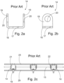
- FIGs 2a and 2b show a known bracket for a pivot rod in a doctor arrangement.
- This bracket is made of sheet metal, and it has disadvantages as previously stated.
- the bracket 14 has a base 16 with a mounting aperture 17. By using a bolt 18 the bracket 14 is fixed to a doctor beam 15 or other suitable support structure.
- the bracket has also adjacent ears 19 with a hole 20 arranged perpendicular to the base 16.
- a pivot rod 13 is led though the holes 20.
- On the left one loading finger 21 is shown, and the pivot rod 13 goes through the loading finger 21, which is fixed to a top plate 23.
- These top brackets are like the bracket 14 as a base bracket bolted to the doctor beam.
- the top plate and the doctor blade installed thereto can pivot.
- the bracket 14 is a cast or 3D-printed piece.
- the bracket is extremely rigid. This makes the whole blade holder stiffer than before. Then the bracket can be designed more freely.
- the ears, holes and apertures may be designed independently.
- the base can also be a bit wider than the ears giving extra support for the loading tubes and add rigidity too.
- the base can wider and/or longer than the ears. This enables many advantageous features, i.e. rigidity by adding material in the strategic points, material also let you have openings for the opposite ears to lower the structure and reach below the corners of the loading tubes to support those.
- the brackets according to the invention are shown in Figure 3a in 3D.
- the bracket may be used as a base bracket or top bracket, and they have same basic properties.
- the bracket means either one of shown bracket unless otherwise stated.
- the base bracket functions also with the loading finger and other kind of supports fixed to the top plate.
- the bracket 14 has 3 - 8, preferably 4 - 6 ears 19.
- the bracket 14 has more than one mounting aperture 17.
- the base bracket 35 has three mounting apertures 17 one of which is in the middle.
- the base bracket 35 is also here such dimensioned that the middle mounting aperture 17 hits the threads in the doctor beam in 150 mm interval.
- this new kind of bracket may be installed without changes to the doctor beams. If necessary, more threads may be machined and use more than one bolt with one bracket.
- the bracket 14 has two or three mounting aperture 17.
- the bracket 14 has round corners . Also other shapes are round. In this way, the installation is safe. Also, the loading tubes avoid damages being in contact with the brackets. Actually, since there are more ears, the brackets support and contour to the shape of the loading tubes. In other words, the bracket has a curved shape contouring loading tubes included in the doctor arrangement. This fact significantly reduces the wear of the loading tubes and extends the service life of loading tubes, resulting in a prolonged maintenance interval.
- the base 16 has a recess 25 for an opposite bracket.
- the recess 25 is a through hole.
- the recess is so dimensioned and positioned, that a part of the opposite ear may enter the recess .
- the opposite bracket may be installed closer than before and thereby lower the whole doctor assembly. Simultaneously, the stress to the brackets decreases, so that the brackets will not get broken that soon as in the prior art. At the same time, the loading of the lowered and compact structure also works better.
- the mounting aperture 17 has a counterbore 26 for the bolt.
- the mounting aperture 17 may be arranged with an offset to the hole 20.
- the top bracket having two mounting apertures 17 arranged on a line 27 perpendicular to another line 28 extending through the holes 20.
- the pivot rod goes between the mounting apertures 17.
- the mounting aperture 17 has an internal thread. Again, this is realized in the top bracket. In this way, the brackets are easy to screw to the top plate. Internal threads may be arranged to the base bracket also, but then the bolt should go through the doctor beam or other doctor blade holder support structure in question.
- Figure 4a shows the doctor arrangement according to the invention from above. Also two embodiments are shown simultaneously. These embodiments are shown separately in Figures 4b and 4c .
- the doctor arrangement is fixed to the doctor beam 15 with several bolts 18.
- a base plate 29 forming support to loading tubes 30.
- the base plate 29 may consist of several parts arranged end to end, like in Figure 5a .
- the base plate 29 has elongated holes 31 for bolts with 150 mm interval.
- top plate 23 with top brackets 22 and a jaw part 32 also screwed to the top plate 23.
- the doctor blade 11 is supported by a blade holder 12, which includes a top plate 23 and a jaw part 32.
- the jaw part 32 is a separate piece screwed to the top plate 23.
- loading fingers are redundant.
- the bracket according to the invention can be use with various kinds of blade holder.
- a loading tube 30 on both side of the pivot rod 13.
- the loading tubes are usually positioned after installing the base plate. Then the blade holder is positioned, and the pivot rod is installed and locked in place ( Figure 5d ).
- the doctor blade 11 as well as the doctor arrangement has a length of several meters, from 1 to 11 meter extending in cross-machine direction.
- the doctor blade has a width from 5 to 20 centimeters extending in machine direction.
- Figures 4b - 4e show different types of form locking for the doctor blades.
- other kind of doctor blades may be used, like foil blades (not shown).
- stiffening fingers 33 on top of the top plate 23 is stiff in the loading direction but can still adapt to the roll surface. Also the heads of the screws are hidden avoiding thereby the wearing of said heads.
- the loading tubes 30 are provided between the top plate 23 and the base plate 29.
- the doctor blade 11 is loaded by pressurizing the hindmost loading tube 30.
- the doctor blade can be detached from the surface to be doctored by simultaneously depressurizing the hindmost tube 30 and pressurizing the anterior tube 30 for a doctor blade replacement, for example.
- the doctor blade may be pull sideways from the blade holder and push back the new one.
- the elongated holes 31 are in 150 mm interval.
- the base plate with the brackets may be installed in the existing threads.
- Figure 5a shows three base brackets 35. One has six ears, and it will be fixed with one bolt. The other two brackets are shorter, but surprisingly cut out of a long bracket thereby including four and two ears, respectively. In this way, one mold is sufficient to manufacture the bracket and different length of doctor arrangements can be covered with one kind of bracket.
- Figure 5b - 5d the rightmost base bracket 35 is cut-out just like in Figure 5a .
- the outermost base bracket 35 is cut-out, but the next is a uniform base bracket 35 with six ears.
- stiffening fingers 33 are screwed on top of the top plate 23.
- the pivot rod 13 has conical tip for facilitating the installation of the pivot rod. At the end, the pivot rod 13 is secured with a lock piece 34.
- the novel doctor arrangement can be taken into use without major equipment changes or investments. Also, the doctor arrangement can be installed even in tight positions. In most cases, it is sufficient to changes only the base brackets to repair the doctor assembly.
- the shown top brackets are used. With the new brackets, there are brackets side by side, not only in 150 mm interval. This stiffens the doctor assembly further. Also, the pivot rod may be more flexible since the distance between two ears is short.
Landscapes
- Paper (AREA)
Abstract
Description
- The invention relates to a bracket for a pivot rod in a doctor arrangement, which bracket has a base with a mounting aperture and adjacent ears with a hole for a pivot rod arranged perpendicular to the base. The invention also relates to a doctor arrangement for a fiber web machine.
-
US-patent number 5279710 discloses a doctor blade supporting structure for paper making rolls. Generally, the doctor blade is for cleaning the roll surface of a roll in a fiber web machine. Depending on the position, the doctor blade also removes water or the fiber web itself. The roll surface may be smooth, grooved or drilled, for example. The supporting structure includes a blade holder which is pivotally fixed to a doctor beam, for example. Here, the blade holder includes several parallel loading fingers which are screwed to a top plate. Then there are brackets fixed to the doctor beam at the point of each loading finger. The bracket has a base with a mounting aperture and adjacent ears with a hole. While the fingers and brackets are targeted to each other a pivot rod is led though the holes and the loading fingers. Thus the blade holder can be pivoted in relation to the doctor beam. For pivoting, there are loading tubes in connection with the top plate. - The blade holders position the doctor blade firmly against the roll, accommodate roll surface irregularities, facilitate rapid blade changes, and, within limits, compensate for thermal expansion. Proper doctoring is critical to many industrial processes like fiber web production.
- The known brackets are manufactured from sheet metal. A strip of sheet metal is first stamped and then bent as a U-shape bracket.
- Thereby there are two ears per bracket for supporting the pivot rod. The bracket has also a base with a mounting aperture. Thus one mounting bolt supports the bracket. Usually, there are mounting bolts in 150 mm intervals.
- In practice, one or more brackets will break in the corners, i.e. at the point where the base changes to the ears. First, the stress from the bending of the sheet metal weakens the structural integrity . At the same time, the highest stress points locate at the corners. The sheet metal is also too thin and is prone to stress corrosion cracking. The brackets hold the whole blade holder. If the brackets break, the blade holder will loosen. Also the corners and edges of the bracket are sharp and will easily damage the loading tubes. At the same time, the brackets do not support or help the loading tubes maintain their shape on the sides. This reduces the amount of travel the loading tube can move up and down to load and unload the doctor blade. In practice, one mounting bolt and two ears provide improper support to the top plate for uniform loading across a 150 mm span. Thus the top plate and the pivot rod may bend which further increases the stress to the brackets.
- It is an object of the invention to provide a novel bracket for a pivot rod in a doctor arrangement with proper durability and load capacity. Another object of the invention is to provide a novel doctor arrangement for a fiber web machine which arrangement is simple and compact but has rigid support for the blade holder and can be utilized in various positions and with different doctor blades. The arrangement can be made lower and to contour adjacent loading tubes which enhances loading actions. The characteristic features of the bracket and the doctor arrangement according to this invention are stated in the accompanying Claims. The bracket is manufactured in a new way, and it has unique properties. In this way, the doctor arrangement functions accurately and is long lasting. With a new kind of bracket, the doctor arrangement remains simple, and it is easy to place even in tight or in other ways demanding positions.
- The invention is described below in detail by referring to the enclosed drawings which illustrate some of the embodiments of the invention, in which
- Figure 1
- shows a doctor arrangement according to the invention adapted to the vicinity of a surface to be doctored,
- Figure 2a
- shows a cross section of one known bracket seen from the front,
- Figure 2b
- shows a cross section of the bracket of
Figure 2a seen from the side, - Figure 2c
- shows a cross section of one known doctor arrangement seen in the machine direction,
- Figure 3a
- shows the brackets according to the invention in 3D,
- Figure 3b
- shows a side view of the brackets of
Figure 3a , - Figure 4a
- shows a top view of the doctor arrangement according to the invention including two embodiments,
- Figure 4b
- shows a cross section from line A - A of
Figure 4a , - Figure 4c
- shows a cross section from line B - B of
Figure 4a , - Figure 4d
- shows a modification of
Figure 4b , - Figure 4e
- shows a modification of
Figure 4c , - Figure 5a
- shows a bottom view of the doctor arrangement according to the invention,
- Figure 5b
- shows a cross section of the doctor arrangement seen in the machine direction before the brackets are targeted,
- Figure 5c
- shows the doctor arrangement of
Figure 5a after the brackets are targeted without any pivot rod, - Figure 5d
- shows another embodiment like in
Figure 5c fully installed. -
Figure 1 shows the doctor arrangement according to the invention adapted to the vicinity of asurface 10 to be doctored. The doctor arrangement is especially for a fiber web machines such as paper, board, and tissue machines. Here onedoctor blade 11 is fixed to adoctor beam 15. Also other kinds of support structures for the doctor blade holder may be used. Here thesurface 10 rotates counterclockwise. The surface can be, for example, the surface of a drying cylinder. Then the doctor blade keeps the surface clean. The doctor arrangement is also suitable for doctoring polymer coated rolls, belts, and transfer belts as well as open-surfaced rolls. In a fiber web machine, such as a paper or board or tissue machine, open-surfaced rolls are used for several varied reasons . In a suction roll, for example, the shell is perforated for leading a vacuum effect from the inside of the roll to the outside of it. In other words, in the wet end of the machine, the doctored rolls have some void volume for water to escape. The void volume can be grooves, blind holes and/or through holes . Whereas in the dry end and finishing part of the machine most of the doctored rolls have a smooth surface. The holes make the shell open-surfaced. On the other hand, grooved rolls are also used, in which the shell surface is grooved mainly for improving dewatering. A suction roll with a grooved surface also exists, the shell of which is provided with both holes and grooves. In addition to or instead of grooves, blind bores, for example, can be used. Soft coatings are also used in the rolls while belts and transfer belts are soft surfaced by their nature. In addition, the surface of a belt, for example, can be grooved. The doctor blade removes water and impurities from the surface. Also, the doctor blade may remove the fiber web off the surface. In practice, in the center roll doctoring is crucial. So, there are even two consequent doctor blade at one roll. - The modern doctor arrangement includes a
blade holder 12 arranged pivotably by apivot rod 13 supported tobrackets 14. In this way, only the blade holder pivots with the doctor blade . In the embodiment ofFigure 1 , thedoctor beam 15 is a rigid structure. Thedoctor beam 15 is supported at its ends and there are setting means for adjusting the angle of the doctor beam 15 (not shown) . The actual loading of the doctor blade is done by pivoting the blade holder. -
Figures 2a and 2b show a known bracket for a pivot rod in a doctor arrangement. This bracket is made of sheet metal, and it has disadvantages as previously stated. Thebracket 14 has a base 16 with a mountingaperture 17. By using abolt 18 thebracket 14 is fixed to adoctor beam 15 or other suitable support structure. The bracket has alsoadjacent ears 19 with ahole 20 arranged perpendicular to thebase 16. InFigure 2c , apivot rod 13 is led though theholes 20. On the left, oneloading finger 21 is shown, and thepivot rod 13 goes through theloading finger 21, which is fixed to atop plate 23. Then there are twotop brackets 22 also fixed to thetop plate 23. These top brackets are like thebracket 14 as a base bracket bolted to the doctor beam. Thus the top plate and the doctor blade installed thereto can pivot. - According to the invention, the
bracket 14 is a cast or 3D-printed piece. In this way many advantages are achieved. First, the bracket is extremely rigid. This makes the whole blade holder stiffer than before. Then the bracket can be designed more freely. Advantageously, there is a thickening 24 in connection with thebase 16 and theear 19. In other words, the corners are stiff, and they have good load capacity. Simultaneously, the ears, holes and apertures may be designed independently. The base can also be a bit wider than the ears giving extra support for the loading tubes and add rigidity too. The base can wider and/or longer than the ears. This enables many advantageous features, i.e. rigidity by adding material in the strategic points, material also let you have openings for the opposite ears to lower the structure and reach below the corners of the loading tubes to support those. - The brackets according to the invention are shown in
Figure 3a in 3D. The bracket may be used as a base bracket or top bracket, and they have same basic properties. Thus the bracket means either one of shown bracket unless otherwise stated. However, the base bracket functions also with the loading finger and other kind of supports fixed to the top plate. Preferably, thebracket 14 has 3 - 8, preferably 4 - 6ears 19. Thus there are much more ears compared to the known technology, which increases the rigidity. And more, thebracket 14 has more than one mountingaperture 17. Thus the bracket can be fixed more firmly. Here thebase bracket 35 has three mountingapertures 17 one of which is in the middle. Thebase bracket 35 is also here such dimensioned that themiddle mounting aperture 17 hits the threads in the doctor beam in 150 mm interval. Thus this new kind of bracket may be installed without changes to the doctor beams. If necessary, more threads may be machined and use more than one bolt with one bracket. Thus, thebracket 14 has two or three mountingaperture 17. - Advantageously, the
bracket 14 has round corners . Also other shapes are round. In this way, the installation is safe. Also, the loading tubes avoid damages being in contact with the brackets. Actually, since there are more ears, the brackets support and contour to the shape of the loading tubes. In other words, the bracket has a curved shape contouring loading tubes included in the doctor arrangement. This fact significantly reduces the wear of the loading tubes and extends the service life of loading tubes, resulting in a prolonged maintenance interval. - Further, the
base 16 has arecess 25 for an opposite bracket. In the embodiment ofFigure 3a , therecess 25 is a through hole. The recess is so dimensioned and positioned, that a part of the opposite ear may enter the recess . Thus the opposite bracket may be installed closer than before and thereby lower the whole doctor assembly. Simultaneously, the stress to the brackets decreases, so that the brackets will not get broken that soon as in the prior art. At the same time, the loading of the lowered and compact structure also works better. - In the shown
base bracket 35 the mountingaperture 17 has acounterbore 26 for the bolt. Thus there is room for the bolt even the bolt is in line of the pivot rod, like inFigure 4b and 4c . On contrary, the mountingaperture 17 may be arranged with an offset to thehole 20. This is realized in the top bracket having two mountingapertures 17 arranged on aline 27 perpendicular to anotherline 28 extending through theholes 20. In this way, the pivot rod goes between the mountingapertures 17. Advantageously, the mountingaperture 17 has an internal thread. Again, this is realized in the top bracket. In this way, the brackets are easy to screw to the top plate. Internal threads may be arranged to the base bracket also, but then the bolt should go through the doctor beam or other doctor blade holder support structure in question. -
Figure 4a shows the doctor arrangement according to the invention from above. Also two embodiments are shown simultaneously. These embodiments are shown separately inFigures 4b and 4c . Apart from the embodiment in question, the doctor arrangement is fixed to thedoctor beam 15 withseveral bolts 18. Here there is also abase plate 29 forming support toloading tubes 30. During installation, the base plate is first attached with bolts through aperture of the brackets. Thebase plate 29 may consist of several parts arranged end to end, like inFigure 5a . Here thebase plate 29 has elongatedholes 31 for bolts with 150 mm interval. Thus this new kind of doctor assembly can be easily installed to the existing doctor beams. - Then there is a
top plate 23 withtop brackets 22 and ajaw part 32 also screwed to thetop plate 23. Thedoctor blade 11 is supported by ablade holder 12, which includes atop plate 23 and ajaw part 32. Here thejaw part 32 is a separate piece screwed to thetop plate 23. In other words, loading fingers are redundant. However, the bracket according to the invention can be use with various kinds of blade holder. Between the base plate and top plate there is aloading tube 30 on both side of thepivot rod 13. Thus theblade holder 12 may be pivoted back and forth, and thereby load and unload the doctor blade against the surface. The loading tubes are usually positioned after installing the base plate. Then the blade holder is positioned, and the pivot rod is installed and locked in place (Figure 5d ). - The
doctor blade 11 as well as the doctor arrangement has a length of several meters, from 1 to 11 meter extending in cross-machine direction. The doctor blade has a width from 5 to 20 centimeters extending in machine direction.Figures 4b - 4e show different types of form locking for the doctor blades. Also other kind of doctor blades may be used, like foil blades (not shown). There can also be stiffeningfingers 33 on top of thetop plate 23. Then the top plate is stiff in the loading direction but can still adapt to the roll surface. Also the heads of the screws are hidden avoiding thereby the wearing of said heads. - The
loading tubes 30 are provided between thetop plate 23 and thebase plate 29. Here thedoctor blade 11 is loaded by pressurizing thehindmost loading tube 30. Correspondingly, the doctor blade can be detached from the surface to be doctored by simultaneously depressurizing thehindmost tube 30 and pressurizing theanterior tube 30 for a doctor blade replacement, for example. The doctor blade may be pull sideways from the blade holder and push back the new one. With a blade holder design ofFigures 4b and 4c utilizing thetop plate 23, the supporting and loading effect of theblade holder 12 can be extended sufficiently far. - In
Figure 5a , theelongated holes 31 are in 150 mm interval. In this way the base plate with the brackets may be installed in the existing threads.Figure 5a shows threebase brackets 35. One has six ears, and it will be fixed with one bolt. The other two brackets are shorter, but surprisingly cut out of a long bracket thereby including four and two ears, respectively. In this way, one mold is sufficient to manufacture the bracket and different length of doctor arrangements can be covered with one kind of bracket. InFigure 5b - 5d therightmost base bracket 35 is cut-out just like inFigure 5a . - In
Figure 5d , theoutermost base bracket 35 is cut-out, but the next is auniform base bracket 35 with six ears. Here, also stiffeningfingers 33 are screwed on top of thetop plate 23. Thepivot rod 13 has conical tip for facilitating the installation of the pivot rod. At the end, thepivot rod 13 is secured with alock piece 34. - The novel doctor arrangement can be taken into use without major equipment changes or investments. Also, the doctor arrangement can be installed even in tight positions. In most cases, it is sufficient to changes only the base brackets to repair the doctor assembly. Advantageously, also the shown top brackets are used. With the new brackets, there are brackets side by side, not only in 150 mm interval. This stiffens the doctor assembly further. Also, the pivot rod may be more flexible since the distance between two ears is short.
Claims (15)
- Bracket for a pivot rod in a doctor arrangement, which bracket (14) has a base (16) with a mounting aperture (17) and adjacent ears (19) with a hole (20) for a pivot rod (13) arranged perpendicular to the base (16), characterized in that the bracket (14) is a cast or 3D-printed piece.
- Bracket according to claim 1, characterized in that the bracket (14) has 3 - 8, preferably 4 - 6 ears (19).
- Bracket according to claim 1 or 2, characterized in that the bracket (14) has more than one mounting aperture (17).
- Bracket according to any of claims 1 - 3, characterized in that the bracket (14) has round corners.
- Bracket according to any of claims 1 - 4, characterized in that the base (16) has a recess (25) for an opposite bracket.
- Bracket according to claim 5, characterized in that the recess (25) is a through hole.
- Bracket according to any of claims 1 - 6, characterized in that the mounting aperture (17) is arranged with an offset to the hole (20).
- Bracket according to any of claims 1 - 7, characterized in that there is a thickening (24) in connection with the base (16) and the ear (19).
- Bracket according to any of claims 1 - 8, characterized in that the mounting aperture (17) has an internal thread.
- Bracket according to any of claims 1 - 9, characterized in that the base (16) has two mounting apertures (17).
- Bracket according to claim 10, characterized in that said two mounting apertures (17) are arranged on a line (27) perpendicular to another line (LI) extending through the holes (20).
- Doctor arrangement for a fiber web machine, which doctor arrangement includes a blade holder (12) arranged pivotably by a pivot rod (13) supported to brackets (14), characterized in that each bracket (14) is a bracket according to any of claims 1 - 11.
- Doctor arrangement according to claim 12, characterized in that there are brackets (14) side by side.
- Doctor arrangement according to claim 12 or 13, characterized in that the bracket (14) is screwed directly on the top plate (23).
- Doctor arrangement according to any of claims 12 - 14, characterized in that the bracket (14) has a curved shape contouring loading tubes (30) included in the doctor arrangement.
Applications Claiming Priority (2)
| Application Number | Priority Date | Filing Date | Title |
|---|---|---|---|
| US202263320493P | 2022-03-16 | 2022-03-16 | |
| FI20225242A FI131487B1 (en) | 2022-03-18 | 2022-03-18 | Bracket for a pivot rod in a doctor arrangement and doctor arrangement for a fiber web machine |
Publications (2)
| Publication Number | Publication Date |
|---|---|
| EP4245912A2 true EP4245912A2 (en) | 2023-09-20 |
| EP4245912A3 EP4245912A3 (en) | 2023-12-20 |
Family
ID=85556675
Family Applications (1)
| Application Number | Title | Priority Date | Filing Date |
|---|---|---|---|
| EP23160877.9A Pending EP4245912A3 (en) | 2022-03-16 | 2023-03-09 | Bracket for a pivot rod in a doctor arrangement and doctor arrangement for a fiber web machine |
Country Status (2)
| Country | Link |
|---|---|
| US (1) | US12312744B2 (en) |
| EP (1) | EP4245912A3 (en) |
Citations (1)
| Publication number | Priority date | Publication date | Assignee | Title |
|---|---|---|---|---|
| US5279710A (en) | 1988-11-16 | 1994-01-18 | Aikawa Iron Works, Co., Ltd. | Doctor blade supporting structure |
Family Cites Families (10)
| Publication number | Priority date | Publication date | Assignee | Title |
|---|---|---|---|---|
| US3859690A (en) * | 1972-10-02 | 1975-01-14 | Ross Ltd James | Doctor blade assembly |
| US4665859A (en) * | 1985-12-11 | 1987-05-19 | Thermo Electron-Web Systems, Inc. | Finger-type doctor blade holder |
| US5103732A (en) * | 1991-02-14 | 1992-04-14 | Ward Holding Company, Inc. | Doctor blade head assembly and printing apparatus therewith |
| US6119595A (en) * | 1997-10-06 | 2000-09-19 | R. J. Reynolds Tobacco Company | Gravure printing press with encapsulated ink applicator and method |
| US7867364B2 (en) * | 2006-08-16 | 2011-01-11 | Kadant Inc. | Doctor blade holder permitting efficient assembly of doctor assemblies and replacement of doctor blades |
| FI124219B (en) | 2007-11-14 | 2014-05-15 | Valmet Technologies Inc | Creator device for detaching the web from a moving surface in a fiber web machine |
| EP2235258B1 (en) * | 2007-12-06 | 2011-08-24 | Kadant Inc. | Doctor blade holder |
| ES2856212T3 (en) * | 2013-04-26 | 2021-09-27 | Kadant Inc | Scraper holder with vibration mitigation |
| FI131234B1 (en) * | 2022-09-23 | 2024-12-19 | Valmet Technologies Oy | Stud for a doctor blade holder in a fiber web machine and doctor blade holder assembly for a fiber web machine |
| EP4343060A3 (en) * | 2022-09-23 | 2024-05-01 | Valmet Technologies Oy | Stud for a doctor blade holder in a fiber web machine and doctor blade holder assembly for a fiber web machine |
-
2023
- 2023-03-03 US US18/178,133 patent/US12312744B2/en active Active
- 2023-03-09 EP EP23160877.9A patent/EP4245912A3/en active Pending
Patent Citations (1)
| Publication number | Priority date | Publication date | Assignee | Title |
|---|---|---|---|---|
| US5279710A (en) | 1988-11-16 | 1994-01-18 | Aikawa Iron Works, Co., Ltd. | Doctor blade supporting structure |
Also Published As
| Publication number | Publication date |
|---|---|
| US12312744B2 (en) | 2025-05-27 |
| EP4245912A3 (en) | 2023-12-20 |
| US20240084510A1 (en) | 2024-03-14 |
Similar Documents
| Publication | Publication Date | Title |
|---|---|---|
| US6942734B2 (en) | Treatment equipment | |
| EP2510152B1 (en) | Doctor blade for a fiber web machine and doctor arrangement in a fiber web machine | |
| EP4245912A2 (en) | Bracket for a pivot rod in a doctor arrangement and doctor arrangement for a fiber web machine | |
| EP4343060A2 (en) | Stud for a doctor blade holder in a fiber web machine and doctor blade holder assembly for a fiber web machine | |
| EP0479748A1 (en) | Method and device in the drying section of a paper machine in the threading of the web | |
| FI20225242A1 (en) | Bracket for a twist bar in a scraper arrangement and scraper arrangement for a fiber web machine | |
| CN116770623A (en) | Doctor device and carrier for a pivot shaft of a doctor device | |
| CA2793160C (en) | Vacuum equipment for a fiber web machine and a fiber web machine provided with vacuum equipment | |
| JP2977282B2 (en) | Tissue paper web forming method | |
| FI131234B1 (en) | Stud for a doctor blade holder in a fiber web machine and doctor blade holder assembly for a fiber web machine | |
| JP5444362B2 (en) | Twin fabric forming part with multiple drain shoes | |
| US8771473B2 (en) | Doctor blade for a fiber web machine and doctor arrangement in a fiber web machine | |
| WO2010139857A1 (en) | Device for transferring a web-like material in a fiber web machine and a fiber web machine | |
| EP2927369A1 (en) | Doctor device for a fiber web machine and doctor arrangement in a fiber web machine | |
| US11643780B2 (en) | Blowing equipment for doctor equipment of a fiber web machine and fiber web machine doctor equipment equipped with blowing equipment | |
| EP1851378A1 (en) | Arrangement in the press section of a web- forming machine and a doctor blade | |
| US6736938B2 (en) | Headbox and arrangement and method for mounting a vane thereof | |
| US20220090320A1 (en) | Paper web air foil of a papermaking machine | |
| WO2011012772A1 (en) | Doctoring device for a fiber web machine and a doctor arrangement in a fiber web machine | |
| CN115142290A (en) | Doctor blade for a fiber web machine and doctor arrangement in a fiber web machine | |
| CN1714036A (en) | Cutting device | |
| WO2005073460A1 (en) | Dewatering device for a paper machine | |
| MXPA01003275A (en) | Bridge device for paper forming equipment and method |
Legal Events
| Date | Code | Title | Description |
|---|---|---|---|
| PUAI | Public reference made under article 153(3) epc to a published international application that has entered the european phase |
Free format text: ORIGINAL CODE: 0009012 |
|
| STAA | Information on the status of an ep patent application or granted ep patent |
Free format text: STATUS: THE APPLICATION HAS BEEN PUBLISHED |
|
| AK | Designated contracting states |
Kind code of ref document: A2 Designated state(s): AL AT BE BG CH CY CZ DE DK EE ES FI FR GB GR HR HU IE IS IT LI LT LU LV MC ME MK MT NL NO PL PT RO RS SE SI SK SM TR |
|
| PUAL | Search report despatched |
Free format text: ORIGINAL CODE: 0009013 |
|
| AK | Designated contracting states |
Kind code of ref document: A3 Designated state(s): AL AT BE BG CH CY CZ DE DK EE ES FI FR GB GR HR HU IE IS IT LI LT LU LV MC ME MK MT NL NO PL PT RO RS SE SI SK SM TR |
|
| RIC1 | Information provided on ipc code assigned before grant |
Ipc: D21G 3/00 20060101AFI20231113BHEP |
|
| STAA | Information on the status of an ep patent application or granted ep patent |
Free format text: STATUS: REQUEST FOR EXAMINATION WAS MADE |
|
| 17P | Request for examination filed |
Effective date: 20240619 |
|
| RBV | Designated contracting states (corrected) |
Designated state(s): AL AT BE BG CH CY CZ DE DK EE ES FI FR GB GR HR HU IE IS IT LI LT LU LV MC ME MK MT NL NO PL PT RO RS SE SI SK SM TR |