EP4245891A1 - Anode for anion exchange membrane water electrolysis - Google Patents
Anode for anion exchange membrane water electrolysis Download PDFInfo
- Publication number
- EP4245891A1 EP4245891A1 EP21892325.8A EP21892325A EP4245891A1 EP 4245891 A1 EP4245891 A1 EP 4245891A1 EP 21892325 A EP21892325 A EP 21892325A EP 4245891 A1 EP4245891 A1 EP 4245891A1
- Authority
- EP
- European Patent Office
- Prior art keywords
- exchange membrane
- anion exchange
- water electrolysis
- electrode
- membrane water
- Prior art date
- Legal status (The legal status is an assumption and is not a legal conclusion. Google has not performed a legal analysis and makes no representation as to the accuracy of the status listed.)
- Pending
Links
Images










Classifications
-
- C—CHEMISTRY; METALLURGY
- C25—ELECTROLYTIC OR ELECTROPHORETIC PROCESSES; APPARATUS THEREFOR
- C25B—ELECTROLYTIC OR ELECTROPHORETIC PROCESSES FOR THE PRODUCTION OF COMPOUNDS OR NON-METALS; APPARATUS THEREFOR
- C25B11/00—Electrodes; Manufacture thereof not otherwise provided for
- C25B11/04—Electrodes; Manufacture thereof not otherwise provided for characterised by the material
- C25B11/051—Electrodes formed of electrocatalysts on a substrate or carrier
- C25B11/073—Electrodes formed of electrocatalysts on a substrate or carrier characterised by the electrocatalyst material
- C25B11/091—Electrodes formed of electrocatalysts on a substrate or carrier characterised by the electrocatalyst material consisting of at least one catalytic element and at least one catalytic compound; consisting of two or more catalytic elements or catalytic compounds
-
- C—CHEMISTRY; METALLURGY
- C25—ELECTROLYTIC OR ELECTROPHORETIC PROCESSES; APPARATUS THEREFOR
- C25B—ELECTROLYTIC OR ELECTROPHORETIC PROCESSES FOR THE PRODUCTION OF COMPOUNDS OR NON-METALS; APPARATUS THEREFOR
- C25B1/00—Electrolytic production of inorganic compounds or non-metals
- C25B1/01—Products
- C25B1/02—Hydrogen or oxygen
- C25B1/04—Hydrogen or oxygen by electrolysis of water
-
- C—CHEMISTRY; METALLURGY
- C25—ELECTROLYTIC OR ELECTROPHORETIC PROCESSES; APPARATUS THEREFOR
- C25B—ELECTROLYTIC OR ELECTROPHORETIC PROCESSES FOR THE PRODUCTION OF COMPOUNDS OR NON-METALS; APPARATUS THEREFOR
- C25B11/00—Electrodes; Manufacture thereof not otherwise provided for
- C25B11/04—Electrodes; Manufacture thereof not otherwise provided for characterised by the material
- C25B11/051—Electrodes formed of electrocatalysts on a substrate or carrier
- C25B11/052—Electrodes comprising one or more electrocatalytic coatings on a substrate
-
- C—CHEMISTRY; METALLURGY
- C25—ELECTROLYTIC OR ELECTROPHORETIC PROCESSES; APPARATUS THEREFOR
- C25B—ELECTROLYTIC OR ELECTROPHORETIC PROCESSES FOR THE PRODUCTION OF COMPOUNDS OR NON-METALS; APPARATUS THEREFOR
- C25B11/00—Electrodes; Manufacture thereof not otherwise provided for
- C25B11/04—Electrodes; Manufacture thereof not otherwise provided for characterised by the material
- C25B11/051—Electrodes formed of electrocatalysts on a substrate or carrier
- C25B11/055—Electrodes formed of electrocatalysts on a substrate or carrier characterised by the substrate or carrier material
- C25B11/057—Electrodes formed of electrocatalysts on a substrate or carrier characterised by the substrate or carrier material consisting of a single element or compound
- C25B11/061—Metal or alloy
-
- C—CHEMISTRY; METALLURGY
- C25—ELECTROLYTIC OR ELECTROPHORETIC PROCESSES; APPARATUS THEREFOR
- C25B—ELECTROLYTIC OR ELECTROPHORETIC PROCESSES FOR THE PRODUCTION OF COMPOUNDS OR NON-METALS; APPARATUS THEREFOR
- C25B11/00—Electrodes; Manufacture thereof not otherwise provided for
- C25B11/04—Electrodes; Manufacture thereof not otherwise provided for characterised by the material
- C25B11/051—Electrodes formed of electrocatalysts on a substrate or carrier
- C25B11/073—Electrodes formed of electrocatalysts on a substrate or carrier characterised by the electrocatalyst material
- C25B11/075—Electrodes formed of electrocatalysts on a substrate or carrier characterised by the electrocatalyst material consisting of a single catalytic element or catalytic compound
- C25B11/077—Electrodes formed of electrocatalysts on a substrate or carrier characterised by the electrocatalyst material consisting of a single catalytic element or catalytic compound the compound being a non-noble metal oxide
-
- C—CHEMISTRY; METALLURGY
- C25—ELECTROLYTIC OR ELECTROPHORETIC PROCESSES; APPARATUS THEREFOR
- C25B—ELECTROLYTIC OR ELECTROPHORETIC PROCESSES FOR THE PRODUCTION OF COMPOUNDS OR NON-METALS; APPARATUS THEREFOR
- C25B9/00—Cells or assemblies of cells; Constructional parts of cells; Assemblies of constructional parts, e.g. electrode-diaphragm assemblies; Process-related cell features
- C25B9/17—Cells comprising dimensionally-stable non-movable electrodes; Assemblies of constructional parts thereof
- C25B9/19—Cells comprising dimensionally-stable non-movable electrodes; Assemblies of constructional parts thereof with diaphragms
- C25B9/23—Cells comprising dimensionally-stable non-movable electrodes; Assemblies of constructional parts thereof with diaphragms comprising ion-exchange membranes in or on which electrode material is embedded
-
- Y—GENERAL TAGGING OF NEW TECHNOLOGICAL DEVELOPMENTS; GENERAL TAGGING OF CROSS-SECTIONAL TECHNOLOGIES SPANNING OVER SEVERAL SECTIONS OF THE IPC; TECHNICAL SUBJECTS COVERED BY FORMER USPC CROSS-REFERENCE ART COLLECTIONS [XRACs] AND DIGESTS
- Y02—TECHNOLOGIES OR APPLICATIONS FOR MITIGATION OR ADAPTATION AGAINST CLIMATE CHANGE
- Y02E—REDUCTION OF GREENHOUSE GAS [GHG] EMISSIONS, RELATED TO ENERGY GENERATION, TRANSMISSION OR DISTRIBUTION
- Y02E60/00—Enabling technologies; Technologies with a potential or indirect contribution to GHG emissions mitigation
- Y02E60/30—Hydrogen technology
- Y02E60/36—Hydrogen production from non-carbon containing sources, e.g. by water electrolysis
Definitions
- the present disclosure relates to an oxidization electrode for anion exchange membrane water electrolysis.
- PEMWE proton exchange membrane water electrolysis
- AWE alkaline water electrolysis
- alkaline water electrolysis uses an alkaline aqueous solution as a reactant, and requires an electrode material having strong corrosion resistance in alkaline aqueous solution.
- an electrode material candidate a non-platinum-based metal such as nickel, iron, or cobalt, especially, a relatively low cost electrode material can be used. Since the electrode accounts for a significant portion of water electrolysis costs, it has the advantage of lowering hydrogen production costs when using non-platinum based metals.
- the alkaline water electrolysis system has disadvantages in that it requires a large space, has a low current per electrode area, and reduces efficiency due to the high overpotential required during hydrogen production.
- cation exchange membrane water electrolysis has the advantage of allowing a compact system design and having a high energy density.
- this requires a platinum-based metal capable of withstanding the acidic atmosphere of the cation exchange membrane, and thus has the disadvantage of increasing hydrogen production costs.
- anion exchange membrane water electrolysis is a system that can overcome the disadvantages while utilizing the advantages of existing systems. Since it is an alkaline environment, non-platinum metals can be used as electrode materials, and a prominent energy density can be achieved with a compact system design.
- anion exchange membrane water electrolysis has not been studied much compared to existing systems, and exchange membranes and electrode materials that serve as standards for this are not known.
- an oxidization electrode for anion exchange membrane water electrolysis comprising: a nickel metal; and a layered double hydroxide (LDH) with a monolayer structure containing nickel and iron and disposed on one surface or both surfaces of the nickel metal.
- LDH layered double hydroxide
- a method for manufacturing an oxidization electrode for anion exchange membrane water electrolysis comprising a series of processes that use a bottom-up method to synthesize layered double hydroxide (LDH) containing nickel and iron into a monolayer structure, followed by vapor deposition on one surface or both surfaces of the nickel metal.
- LDH layered double hydroxide
- an anion exchange membrane water electrolysis cell comprising: an anion exchange membrane; and a reduction electrode and an oxidation electrode respectively disposed on both sides of the anion exchange membrane, wherein the oxidation electrode is the oxidation electrode of one embodiment described above.
- the oxidization electrode of the one embodiment includes nickel and iron, which are non-precious metals, it can be efficiently produced at low cost within a short time.
- LDH layered double hydroxide
- a layer or an element in case a layer or an element is mentioned to be formed "on" layers or elements, it means that the layer or element is directly formed on the layers or elements, or it means that other layers or elements may be additionally formed between the layers, on a subject, or on a substrate.
- an oxidization electrode for anion exchange membrane water electrolysis comprising: a nickel metal; and a layered double hydroxide (LDH) with a monolayer structure containing nickel and iron and disposed on one surface of the nickel metal.
- LDH layered double hydroxide
- LDH layered double hydroxide
- the oxidation electrode of the one embodiment includes a monolayer-structured catalyst layer, and this monolayer-structured catalyst layer is actually a layered double hydroxide containing nickel and iron.
- the layered double hydroxide (LDH) is a type of ionic solids having a two-dimensional structure.
- n has a multilayer structure of [(AcB)-Z-(AcB)] n , where c represents a metal cation layer, A and B each represent hydroxide ion (OH) layers, Z means a layer containing other anions and neutral molecules (e.g., water), and n means the number of repetitions.
- the inserted anion or neutral molecule (Z) is weakly bound and exchangeable with other anions or neutral molecules. Further, the AcB interlayer distance with an anion or neutral molecule (Z) interposed therebetween is referred to as interlayer basal spacing. 2)
- nickel-iron layered double hydroxide in a bulk state is known to exhibit high catalytic performance.
- NiFe-LDH bulk layered double hydroxide
- B-NiFe-LDH bulk layered double hydroxide
- the B-NiFe-LDH has a monolayer structure as one unit (AcB) comprising a first hydroxide ion (OH-) layer (A), a metal layer (c) containing nickel and iron, and a second hydroxide ion (OH-) layer (B); and includes water or the like as neutral molecules along with other anions such as CO 3 2- and OH - between the two units (AcB) (Z) to form a structure [(AcB)-Z-(AcB)] n in which a plurality of units are stacked.
- AcB monolayer structure as one unit
- Such a B-NiFe-LDH has a great disadvantage when used as an anion exchange membrane water electrolysis catalyst, and a typical reason therefor is low electrical conductivity and low stability.
- the B-NiFe-LDH has drawbacks that while the basal plane serves as a reaction site for the oxygen generation reaction, OH- used as a reactant cannot quickly diffuse into a multilayer structure, and the catalyst is dissolved while having a partially acidic environment between the catalyst layers. This will appear as a major problem in anion exchange membrane water electrolysis, which operates at a higher temperature and higher current than alkaline water electrolysis.
- M-NiFe-LDH has a structure in which all basal planes are exposed to the reactant (OH-). Due to this structure, while OR is consumed, the problem that the catalyst dissolves without generating a partially acidic environment can be solved. In other words, M-NiFe-LDH can solve the problem of low stability caused by B-NiFe-LDH.
- the oxidization electrode of the one embodiment includes a layered double hydroxide (LDH) with a monolayer structure containing nickel and iron.
- LDH layered double hydroxide
- M-NiFe-LDH the nickel-iron layered double hydroxide having a monolayer structure
- M-NiFe-LDH contains only one unit (AcB) and can solve the problems of low electrical conductivity and low stability of B-NiFe-LDH. Specifically, M-NiFe-LDH has a higher intrinsic OER activity than B-NiFe-LDH due to its monolayer structure, and can improve anion exchange membrane water electrolysis performance.
- the M-NiFe-LDH may be produced using a bottom-up method or a top-down method.
- the bottom-up method simplifies a production process and enables more efficient electrode production as compared to the top-down method.
- the electric conductivity can be further complemented by using nickel metal as a substrate.
- the M-NiFe-LDH is more affected by the substrate due to its small thickness relative to the B-NiFe-LDH.
- the electrical conductivity of the oxidization electrode can be further supplemented.
- the oxidation electrode of the one embodiment includes M-NiFe-LDH produced by a bottom-up method as a catalyst layer, and includes nickel metal as a substrate, thereby improving both the stability and the electrical conductivity.
- a weight ratio of nickel/iron in the layered double hydroxide (M-NiFe-LDH) may be 15/85 to 85/15.
- the weight ratio of nickel/iron is closer to 25/75, overpotential during the oxygen generation reaction can decrease and catalyst performance can increase. As the ratio becomes larger or smaller than this ratio, overpotential during the oxygen generation reaction increases and the catalyst performance deteriorates. Taking this into consideration, the nickel/iron weight ratio can be controlled.
- the weight ratio of nickel/iron in the layered double hydroxide may be controlled within the range of 25/85 to 85/25.
- a loading amount of the layered double hydroxide (M-NiFe-LDH) per one surface of the nickel metal may be 0.1 to 5 mg/cm 2 .
- the performance of the anion exchange membrane water electrolysis cell is improved, so that the highest performance appears at 3 mg/cm 2 , and performance can decrease in the range of greater than 3 mg/cm 2 .
- the loading amount of the layered double hydroxide (M-NiFe-LDH) per one surface of the nickel metal may be controlled within the range of 0.1 mg/cm 2 or more, 0.3 mg/cm 2 or more, 0.6 mg/cm 2 or more, or 1 mg/cm 2 or more, and 5 mg/cm 2 or less, 4.5. mg/cm 2 or less, or 4 mg/cm 2 or less.
- the thickness of the layered double hydroxide (M-NiFe-LDH) may increase in proportion to its loading amount.
- the nickel metal may be a nickel foam (Ni foam) containing a large number of pores therein.
- the porosity of the nickel metal may be 50 to 200 PPI (pores per inch), specifically 70 to 170 PPI, for example 110 PPI.
- the thickness of the nickel metal may be 150 to 350 ⁇ m, specifically 200 to 300 ⁇ m, for example 250 ⁇ m.
- a method for manufacturing an oxidization electrode for anion exchange membrane water electrolysis comprising a series of processes that use a bottom-up method to synthesize layered double hydroxide (LDH) containing nickel and iron into a monolayer structure, followed by vapor deposition on one surface or both surfaces of the nickel metal.
- LDH layered double hydroxide
- a top-down method and a bottom-up method can be considered.
- the one embodiment uses a bottom-up method which simplifies a production process and enables more efficient electrode production as compared with the top-down method.
- the method for manufacturing an oxidization electrode of the one embodiment comprises a step of injecting an alkaline aqueous solution and an aqueous metal solution containing a nickel source and an iron source into an aqueous formamide solution to produce a raw material mixture solution; a step of reacting the raw material mixture solution to produce a layered double hydroxide (LDH) with a monolayer structure containing nickel and iron; and a step of applying the layered double hydroxide onto one surface or both surfaces of nickel metal.
- LDH layered double hydroxide
- NiFe-LDH with a monolayer structure can be produced from B-NiFe-LDH.
- This is a method of increasing the interlayer basal spacing of B-NiFe-LDH through intercalated anion exchange, dispersing it in a formamide solvent, and then then exfoliating each layer by sonication, which requires a long time of about 1-2 weeks.
- the finally obtained M-NiFe-LDH is in a state of being dispersed in a formamide solvent, which may cause problems in the solvent removal step. Since formamide is a liquid with low volatility, rapid drying is impossible. Therefore, when using the top-down method, there is a fatal problem that efficient electrode production is impossible.
- the bottom-up method can produce M-NiFe-LDH through a one-step reaction, which simplifies the production process and enables synthesis within about 1 hour, thus greatly shortening the production time.
- the finally obtained M-NiFe-LDH is in a state of being dispersed in distilled water, and can be quickly dried as compared to the formamide solvent by the top-down method, thus enabling efficient electrode production.
- the aqueous metal solution may include 0.5 to 1.5 wt.%, e.g., 0.7 to 1.3 wt.% of a nickel source; 0.1 to 1.0 wt.%, e.g., 0.2 to 0.7 wt.% of an iron source; and the balance of water relative to the total amount (100 wt.%).
- the nickel and iron contents in the final product i.e., M-NiFe-LDH
- the nickel and iron contents in the final product i.e., M-NiFe-LDH
- the nickel source may be nickel nitrate (Ni(NO 3 ) 2 ) or its hydrate (Ni(NO 3 ) 2 ⁇ 6H 2 O), and the iron source may be iron nitrate (Fe(NO 3 ) 3 ) or its hydrate (Fe(NO 3 ) 3 ⁇ 9H 2 O).
- the alkaline aqueous solution may be an aqueous sodium hydroxide solution.
- the molar concentration of the aqueous sodium hydroxide solution may include 0.05 to 5 M, e.g., 0.1 to 3 M; and the balance of water.
- the aqueous sodium hydroxide solution can serve to provide the OH - required for catalyst synthesis and adjust the pH to 9 ⁇ 11.
- the sodium hydroxide content in the aqueous sodium hydroxide solution satisfies the above range, the desired shape, size, etc. of the catalyst can be obtained.
- the aqueous formamide solution may contain 15 to 40 vol.%, e.g., 20 to 30 vol.% of formamide, and the balance water relative to the total amount (100 vol.%).
- the aqueous formamide solution may serve to interact with hydroxide during catalyst synthesis and suppress growth in the z-axis (layered structure). Therefore, when the formamide content in the aqueous formamide solution satisfies the above range, the layered double hydroxide (M-NiFe-LDH) can be obtained.
- 50 to 200 parts by weight e.g., 70 to 130 parts by weight of the alkaline aqueous solution
- 50 to 200 parts by weight, e.g., 70 to 130 parts by weight of the aqueous metal solution may be mixed based on 100 parts by weight of the aqueous formamide solution.
- the pH of the raw material mixture solution may be controlled within the range of 9 to 11, for example, 9.5 to 10.5 using the alkaline aqueous solution.
- the layered double hydroxide (M-NiFe-LDH) can be satisfactorily synthesized as long as the pH is maintained within the above range.
- the reaction of the raw material mixture solution may be carried out within a temperature range of 70 to 90°C, for example, 75 to 85°C.
- the temperature may affect the rate at which the catalyst is synthesized, thereby affecting the shape, size, and the like of the catalyst.
- the reaction of the raw material mixture solution may be carried out for 1 to 20 minutes, for example, 5 to 15 minutes.
- the reaction time may affect the crystallinity of the catalyst.
- the reaction of the raw material mixture solution may further comprise a step of washing the layered double hydroxide (M-NiFe-LDH) using a washing solvent; and a step of dispersing the washed layered double hydroxide (M-NiFe-LDH) in water.
- the layered double hydroxide (M-NiFe-LDH) is washed with a washing solvent (e.g., a mixed solution of water and ethanol), impurities remaining in the layered double hydroxide (M-NiFe-LDH) are dissolved in the solvent, and then centrifuged to remove a solvent in which the impurities are dissolved
- a washing solvent e.g., a mixed solution of water and ethanol
- the layered double hydroxide (M-NiFe-LDH) thus washed is dispersed in water, so that an aqueous solution containing layered double hydroxide (M-NiFe-LDH) and water can finally be obtained.
- an aqueous solution containing the layered double hydroxide and water can be applied.
- a Nafion solution can be added to the layered double hydroxide and then applied.
- Nafion since Nafion is dispersed and applied together with the catalyst, it can function as a binder to prevent detachment of the catalyst during the reaction.
- the Nafion solution one having a Nafion content of 5 to 10 wt.% relative to the total amount (100 wt.%) can be used.
- a spray drying method When applying the layered double hydroxide, a spray drying method can be used.
- the nickel metal when applying the layered double hydroxide, may be disposed on a hot plate at 70 to 90°C.
- the spray drying it may be advantageous for evenly applying the catalyst.
- the temperature of the nickel metal is within the above range, the evaporation rate of the solvent can be well controlled so that the catalyst can be evenly applied.
- an anion exchange membrane water electrolysis cell comprising: an anion exchange membrane; and a reduction electrode and an oxidation electrode respectively disposed on both sides of the anion exchange membrane, wherein the oxidation electrode is the oxidation electrode of one embodiment described above.
- This may have improved water electrolysis performance by including the oxidation electrode of one embodiment described above.
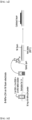
- FIG. 1 shows a water electrolysis cell of one embodiment.
- the water electrolysis cell of the one embodiment may include a potentiostat connected to a reduction electrode and an oxidation electrode, respectively.
- the oxidization electrode As the oxidization electrode, the oxidization electrode of one embodiment described above may be used, and as the reduction electrode, composite coatings of platinum (Pt) and carbon (C) on carbon paper may be used.
- FIG. 1 Although only one water electrolysis cell is shown in FIG. 1 , one water electrolysis cell is used as a unit cell, and a plurality of unit cells may be stacked in series to configure a water electrolysis stack.
- the water electrolyte stack may include an electrolyte tank (not shown), and the electrolyte tank stores an alkaline aqueous solution such as potassium hydroxide (KOH) and sodium hydroxide (NaOH), and may serve to supply this to the anion exchange membrane.
- KOH potassium hydroxide
- NaOH sodium hydroxide
- hydroxide ion (OH - ) which is a decomposition product of the alkaline aqueous solution in the anion exchange membrane, may catalytically react on the surface of the oxidation electrode to generate oxygen, water, and electrons, and electrons can move to the reduction electrode along an external wire.
- electrons and water may catalytically react to generate hydrogen and hydroxide ions (OH - ).
- Oxygen generated at the oxidation electrode and hydrogen generated at the reduction electrode may be moved to and stored in a storage tank (not shown) outside the unit cell.
- Solution A aqueous metal solution
- the metal weight ratio of Ni:Fe is 3:1.
- Solution B alkaline aqueous solution
- the internal temperature of a constant-temperature water bath was prepared to be 80°C.
- the washing process After the washing process is completed, it is dispersed in water and stored. At this time, the concentration can be confirmed through ICP.
- M-NiFe-LDH aqueous solution of Preparation Example 1 an aqueous solution containing M-NiFe-LDH and water (hereinafter, referred to as "M-NiFe-LDH aqueous solution of Preparation Example 1") was obtained.
- the solid content in the M-NiFe-LDH aqueous solution of Preparation Example 1 is about 88.33 wt.% based on 100 wt.% of the total aqueous solution.
- NiCl 2 ⁇ 6H 2 O and 10.7 mg of FeCl 3 were added to 40 ml of deionized water, and sufficiently dispersed by bath sonication to prepare Solution C.
- the metal weight ratio of Ni:Fe is 3:1.
- a nickel foam having a porosity of 110 PPI and a thickness of 250 ⁇ m was disposed on a hot plate at 80°C.
- the sonicated aqueous solution was evenly sprayed on the Ni foam to form a catalyst layer.
- spraying was performed at a spray speed of 2 l/min using a spray drying device (product name: INFINITY CR plus 0,4 [v2.0], manufacturer: INFINITY) to manufacture the oxidation electrode of Example 1 in which the loading amount of the catalyst layer per one surface of the nickel foam was 1.0 mg/cm 2 .
- a spray drying device product name: INFINITY CR plus 0,4 [v2.0], manufacturer: INFINITY
- Each water electrolysis cell was manufactured using the oxidization electrode of Example 1.
- a reduction electrode an electrode in which carbon carried with platinum catalyst (40 wt.% Pt/C) was spray-coated on a carbon paper was used, and an anion exchange membrane (Sustainion TM , Dioxide Materials) was used.
- the oxidation electrode and the reduction electrode were disposed on both sides to manufacture a laminate in which the oxidization electrode/anion exchange membrane/reduction electrode were stacked in this order, and then a gasket was placed and pressurized with a torque of 100 kg f cm to complete the anion exchange membrane electrolysis cell of Example 1.
- the cell has a reaction area of 5 cm 2 , and a titanium block with single serpentine flow-pattern was used as a passage for delivering reactants (1M KOH) and products (oxygen) to the oxidization electrode, and a graphite block with a single serpentine flow-pattern was used as a passage for delivering reactants (1M KOH) and products (hydrogen) to the reduction electrode.
- This block abuts on the gold plated current collector, which is connected to Potentiostat.
- Other details were in accordance with a method for manufacturing an anion exchange membrane water electrolysis cell generally known in the art.
- Example 2 An oxidation electrode and an anion exchange membrane water electrolysis cell of Example 2 were manufactured in the same manner as in Example 1, except that the loading amount of the catalyst layer per one surface of the Ni foam was changed to 2.0 mg/cm 2 .
- Example 3 An oxidation electrode and an anion exchange membrane water electrolysis cell of Example 3 were manufactured in the same manner as in Example 1, except that the loading amount of the catalyst layer per one surface of the Ni foam was changed to 3.0 mg/cm 2 .
- Example 4 An oxidation electrode and an anion exchange membrane water electrolysis cell of Example 4 were manufactured in the same manner as in Example 1, except that the loading amount of the catalyst layer per one surface of the Ni foam was changed to 4.0 mg/cm 2 .
- a nickel foam having a porosity of 110 PPI and a thickness of 250 ⁇ m was disposed on a hot plate at 80°C.
- the sonicated aqueous solution was evenly sprayed on the Ni foam to form a catalyst layer.
- spraying was performed at a spray speed of 2 l/min using a spray drying device (product name: INFINITY CR plus 0,4 [v2.0], manufacturer: INFINITY) to manufacture the oxidation electrode of Comparative Example 1 in which the loading amount of the catalyst layer per one surface of the nickel foam was 1.0 mg/cm 2 .
- a water electrolysis cell of Comparative Example 1 was manufactured in the same manner as in Example 1, except that the oxidization electrode of Comparative Example 1 was used instead of the oxidization electrode of Example 1.
- An oxidation electrode and an anion exchange membrane water electrolysis cell of Comparative Example 2 were manufactured in the same manner as in Comparative Example 1, except that the loading amount of the catalyst layer per one surface of the Ni foam was changed to 1.5 mg/cm 2 .
- An oxidation electrode and an anion exchange membrane water electrolysis cell of Comparative Example 3 were manufactured in the same manner as in Comparative Example 1, except that the loading amount of the catalyst layer per one surface of the Ni foam was changed to 2.0 mg/cm 2 .
- An oxidation electrode and an anion exchange membrane water electrolysis cell of Comparative Example 4 were manufactured in the same manner as in Comparative Example 1, except that the loading amount of the catalyst layer per one surface of the Ni foam was changed to 3.0 mg/cm 2 .
- An oxidation electrode and an anion exchange membrane water electrolysis cell of Comparative Example 5 were manufactured in the same manner as in Comparative Example 1, except that Nickel foam itself was used as an oxidization electrode.
- An oxidation electrode and an anion exchange membrane water electrolysis cell of Comparative Example 6 were manufactured in the same manner as in Comparative Example 1, except that commercially available iridium oxide (IrOx) was used instead of the M-NiFe-LDH powder of Comparative Example 1.
- IrOx commercially available iridium oxide
- FIGS. 4a and 4b are TEM images of Preparation Example 2 (B-NiFe-LDH), and FIG. 4c evaluates the elemental distribution on the same scale.
- FIGS. 4d and 4e are TEM images of Preparation Example 1 (M-NiFe-LDH), and FIG. 4f evaluates the elemental distribution on the same scale.
- FIG. 5 is a diagram showing each XRD pattern of the catalyst (B-NiFe-LDH) of Comparative Example 1 in powder form, the catalyst (M-NiFe-LDH) of Example 1 dispersed in water to form a colloidal phase, and the catalyst (M-NiFe-LDH) of Example 1 dried in an oven into a powder.
- the catalyst (M-NiFe-LDH) of Example 1 is applied in a colloidal phase in the oxidation electrode manufacturing process, but the catalyst (M-NiFe-LDH) of Example 1 exists in a dry state on the oxidation electrode that has been dried after manufacture.
- the catalyst (B-NiFe-LDH) of Comparative Example 1 shows a distinct (003) peak, whereas the (003) peak does not appear when the catalyst (M-NiFe-LDH) of Example 1 is in the colloidal phase. This demonstrates that during the synthesis of the catalyst (M-NiFe-LDH) of Example 1, the growth of NiFe-LDH along the z-axis is suppressed by formamide, and synthesized into a monolayer.
- FIGS. 6a to 6c are SEM images of the oxidation electrode (B-NiFe-LDH on Ni foam) of Comparative Example 1, which confirms that nanoparticles in a bulk state exist in an aggregated state.
- FIGS. 6d to 6f are SEM images of the oxidization electrode (M-NiFe-LDH on Ni foam) of Example 1, which confirms that the monolayer NiFe-LDHs densely adheres and exhibits a smooth surface.
- M-NiFe-LDH when M-NiFe-LDH is used, it has excellent contact characteristics with nickel metal (specifically, Ni foam) and excellent contact characteristics with anion exchange membrane, which can improve the performance of the anion exchange membrane water electrolysis cell.
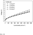
- FIG. 7A A current-voltage graph of each anion exchange membrane water electrolysis cell of Comparative Examples 1 to 5 is shown in FIG. 7A ; a current-voltage graph of each anion exchange membrane water electrolysis cell of Examples 1 to 4 is shown in FIG. 7b ; and a current-voltage graph of each anion exchange membrane water electrolysis cell of Example 3 having the highest efficiency among Examples, and Comparative Example 5 together with Comparative Example 3 having the highest efficiency among Comparative Examples is shown in FIG. 7C .
- Driving conditions are 50°C and 1 A/cm 2 , respectively.
- IrOx lithium oxide
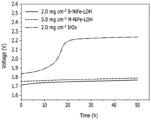
- each anion exchange membrane water electrolysis cell was subjected to a galvanostatic experiment under the conditions of 50°C and 1 A/cm 2 to measure a change in overpotential. The results are shown in FIG. 8 .
- Example 3 in the case of Example 3 and Comparative Example 3, stable driving progressed compared to Comparative Example 6. Among them, it can be seen that the driving of Example 3 is more stable.
Landscapes
- Chemical & Material Sciences (AREA)
- Engineering & Computer Science (AREA)
- Chemical Kinetics & Catalysis (AREA)
- Electrochemistry (AREA)
- Materials Engineering (AREA)
- Metallurgy (AREA)
- Organic Chemistry (AREA)
- Inorganic Chemistry (AREA)
- Electrolytic Production Of Non-Metals, Compounds, Apparatuses Therefor (AREA)
- Electrodes For Compound Or Non-Metal Manufacture (AREA)
- Catalysts (AREA)
- Manufacture Of Macromolecular Shaped Articles (AREA)
Abstract
Specifically, an embodiment of the present disclosure provides an oxidization electrode for anion exchange membrane water electrolysis, comprising: a nickel metal; and a layered double hydroxide (LDH) with a monolayer structure containing nickel and iron and disposed on one surface or both surfaces of the nickel metal.
Description
- This application claims the benefit of
Korean Patent Application No. 10-2020-0150363 filed on November 11, 2020 - The present disclosure relates to an oxidization electrode for anion exchange membrane water electrolysis.
- The importance of technologies capable of environmentally friendly production of hydrogen, which is a next-generation energy source that can solve deletion of fossil fuels and environmental pollution, is being emphasized.
- According to the hydrogen economy revitalization roadmap recently announced by the Ministry of Trade, Industry and Energy of Korea, since a major portion of the hydrogen production is planned to be made by an environmentally friendly method, the development of water electrolysis, which is a representative technology for eco-friendly hydrogen production, is increasingly required.
- In this regard, research on water electrolysis technology using an electrolysis method is being actively conducted, and as typical low-temperature water electrolysis technologies, proton exchange membrane water electrolysis (PEMWE) and alkaline water electrolysis (AWE) are known.
- Among them, alkaline water electrolysis uses an alkaline aqueous solution as a reactant, and requires an electrode material having strong corrosion resistance in alkaline aqueous solution. As an electrode material candidate, a non-platinum-based metal such as nickel, iron, or cobalt, especially, a relatively low cost electrode material can be used. Since the electrode accounts for a significant portion of water electrolysis costs, it has the advantage of lowering hydrogen production costs when using non-platinum based metals. However, the alkaline water electrolysis system has disadvantages in that it requires a large space, has a low current per electrode area, and reduces efficiency due to the high overpotential required during hydrogen production.
- Meanwhile, cation exchange membrane water electrolysis has the advantage of allowing a compact system design and having a high energy density. However, this requires a platinum-based metal capable of withstanding the acidic atmosphere of the cation exchange membrane, and thus has the disadvantage of increasing hydrogen production costs.
- On the other hand, anion exchange membrane water electrolysis (AEMWE) is a system that can overcome the disadvantages while utilizing the advantages of existing systems. Since it is an alkaline environment, non-platinum metals can be used as electrode materials, and a prominent energy density can be achieved with a compact system design.
- However, anion exchange membrane water electrolysis has not been studied much compared to existing systems, and exchange membranes and electrode materials that serve as standards for this are not known.
- It is an object of the present disclosure to provide an oxidization electrode for anion exchange membrane water electrolysis having low cost, high performance and high stability.
- Specifically, in one embodiment of the present disclosure, there is provided an oxidization electrode for anion exchange membrane water electrolysis, comprising: a nickel metal; and a layered double hydroxide (LDH) with a monolayer structure containing nickel and iron and disposed on one surface or both surfaces of the nickel metal.
- In another embodiment of the present disclosure, there is provided a method for manufacturing an oxidization electrode for anion exchange membrane water electrolysis, the method comprising a series of processes that use a bottom-up method to synthesize layered double hydroxide (LDH) containing nickel and iron into a monolayer structure, followed by vapor deposition on one surface or both surfaces of the nickel metal.
- In yet another embodiment of the present disclosure, there is provided an anion exchange membrane water electrolysis cell comprising: an anion exchange membrane; and a reduction electrode and an oxidation electrode respectively disposed on both sides of the anion exchange membrane, wherein the oxidation electrode is the oxidation electrode of one embodiment described above.
- Since the oxidization electrode of the one embodiment includes nickel and iron, which are non-precious metals, it can be efficiently produced at low cost within a short time. By including the layered double hydroxide (LDH) with a monolayer structure containing nickel and iron, it is possible to secure high performance and high stability relative to the multilayer structure.
-
-
FIG. 1 shows the principle of an anion exchange membrane water electrolysis device. -
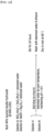
FIG. 2a shows the B-NiFe-LDH synthesis method, andFIG. 2b shows the M-NiFe-LDH synthesis method. -
FIG. 3a shows a method for manufacturing an oxidization electrode using B-NiFe-LDH, andFIG. 3b shows a method for manufacturing an oxidization electrode using M-NiFe-LDH. -
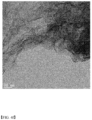
FIGS. 4a and 4b are TEM images of Preparation Example 2 (B-NiFe-LDH), andFIG. 4c is an EDS mapping image at the same scale. -
FIGS. 4d and4e are TEM images of Preparation Example 1 (M-NiFe-LDH), andFIG. 4f is an EDS mapping image at the same scale. -
FIG. 5 is a diagram showing each XRD pattern of the catalyst (B-NiFe-LDH) of Comparative Example 1 in powder form, the catalyst (M-NiFe-LDH) of Example 1 dispersed in water to form a colloidal phase, and the catalyst (M-NiFe-LDH) of Example 1 dried in an oven into a powder. -
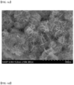
FIGS. 6a to 6c are SEM images of the oxidization electrode (B-NiFe-LDH on Ni foam) of Comparative Example 1, andFIGS. 6d to 6f are SEM images of the oxidization electrode (M-NiFe-LDH on Ni foam) of Example 1. -
FIG. 7a is a current-voltage graph of each anion exchange membrane water electrolysis cell of Comparative Examples 1 to 5;FIG. 7b is a current-voltage graph of each anion exchange membrane water electrolysis cell of Examples 1 to 4; andFIG. 7c is a current-voltage graph of anion exchange membrane water electrolysis cells of Example 3 and Comparative Examples 3 and 5, respectively. -
FIG. 8 is a stability evaluation graph of each anion exchange membrane water electrolysis cell of Example 3, Comparative Example 3, and Comparative Example 6. - The terms "first," "second," etc. are used to explain various elements, and these terms are only used to distinguish one constitutional element from the other constitutional elements.
- Further, the technical terms used herein is for the purpose of describing exemplary embodiments only and is not intended to limit the scope of the invention. The singular forms "a," "an" and "the" are intended to include plural forms, unless the context clearly indicates otherwise. It should be understood that the terms "comprise," "include", "have", etc. are used herein to specify the presence of stated features, integers, steps, components or combinations thereof, but do not preclude the presence or addition of one or more other features, integers, steps, components, or combinations thereof.
- Further, as used herein, in case a layer or an element is mentioned to be formed "on" layers or elements, it means that the layer or element is directly formed on the layers or elements, or it means that other layers or elements may be additionally formed between the layers, on a subject, or on a substrate.
- Although the present disclosure may have various forms and various modifications can be made thereto, specific examples will be exemplified and explained in detail. However, it is not intended to limit the present disclosure to any specific disclosed form, and it should be understood that all the modifications, equivalents or substitutions within the idea and technical scope of the present disclosure are included in the present disclosure.
- In one embodiment of the present disclosure, there is provided an oxidization electrode for anion exchange membrane water electrolysis, comprising: a nickel metal; and a layered double hydroxide (LDH) with a monolayer structure containing nickel and iron and disposed on one surface of the nickel metal.
- This contains nickel and iron, which are non-precious metals, and thus, can be produced at low cost. By including such a layered double hydroxide (LDH) with a monolayer structure containing nickel and iron, it is possible to secure high performance and high stability relative to the multilayer structure.
- 1) In the oxidization electrode of the one embodiment, a layered double hydroxide (LDH) with a monolayer structure containing nickel and iron and located on one surface or both surfaces of the nickel metal functions as an oxygen generation catalyst.
- In other words, the oxidation electrode of the one embodiment includes a monolayer-structured catalyst layer, and this monolayer-structured catalyst layer is actually a layered double hydroxide containing nickel and iron.
- Generally, the layered double hydroxide (LDH) is a type of ionic solids having a two-dimensional structure.
- Specifically, it has a multilayer structure of [(AcB)-Z-(AcB)]n, where c represents a metal cation layer, A and B each represent hydroxide ion (OH) layers, Z means a layer containing other anions and neutral molecules (e.g., water), and n means the number of repetitions.
- In the [AcB-Z-AcB] unit, the inserted anion or neutral molecule (Z) is weakly bound and exchangeable with other anions or neutral molecules. Further, the AcB interlayer distance with an anion or neutral molecule (Z) interposed therebetween is referred to as interlayer basal spacing.
2) In the field of general catalysts, nickel-iron layered double hydroxide in a bulk state is known to exhibit high catalytic performance. - Here, it may be a bulk layered double hydroxide (NiFe-LDH) containing nickel and iron, that is, a layered double hydroxide with a multilayer structure containing nickel and iron. Hereinafter, the bulk layered double hydroxide containing nickel and iron may be referred to as "B-NiFe-LDH".
- Specifically, the B-NiFe-LDH has a monolayer structure as one unit (AcB) comprising a first hydroxide ion (OH-) layer (A), a metal layer (c) containing nickel and iron, and a second hydroxide ion (OH-) layer (B); and includes water or the like as neutral molecules along with other anions such as CO3 2- and OH- between the two units (AcB) (Z) to form a structure [(AcB)-Z-(AcB)]n in which a plurality of units are stacked.
- Such a B-NiFe-LDH has a great disadvantage when used as an anion exchange membrane water electrolysis catalyst, and a typical reason therefor is low electrical conductivity and low stability.
- Specifically, the B-NiFe-LDH has drawbacks that while the basal plane serves as a reaction site for the oxygen generation reaction, OH- used as a reactant cannot quickly diffuse into a multilayer structure, and the catalyst is dissolved while having a partially acidic environment between the catalyst layers. This will appear as a major problem in anion exchange membrane water electrolysis, which operates at a higher temperature and higher current than alkaline water electrolysis.
- On the other hand, unlike B-NiFe-LDH, M-NiFe-LDH has a structure in which all basal planes are exposed to the reactant (OH-). Due to this structure, while OR is consumed, the problem that the catalyst dissolves without generating a partially acidic environment can be solved. In other words, M-NiFe-LDH can solve the problem of low stability caused by B-NiFe-LDH.
- The oxidization electrode of the one embodiment includes a layered double hydroxide (LDH) with a monolayer structure containing nickel and iron. Hereinafter, the nickel-iron layered double hydroxide having a monolayer structure may be referred to as "M-NiFe-LDH".
- M-NiFe-LDH contains only one unit (AcB) and can solve the problems of low electrical conductivity and low stability of B-NiFe-LDH. Specifically, M-NiFe-LDH has a higher intrinsic OER activity than B-NiFe-LDH due to its monolayer structure, and can improve anion exchange membrane water electrolysis performance.
- Meanwhile, in the oxidization electrode of the one embodiment, the M-NiFe-LDH may be produced using a bottom-up method or a top-down method.
- Among them, the bottom-up method simplifies a production process and enables more efficient electrode production as compared to the top-down method.
- A method for producing the M-NiFe-LDH will be described later.
3) Furthermore, the electric conductivity can be further complemented by using nickel metal as a substrate. - Specifically, the M-NiFe-LDH is more affected by the substrate due to its small thickness relative to the B-NiFe-LDH. In this regard, by using a material with high electrical conductivity such as nickel metal (e.g., nickel foam, Ni foam) as a substrate, the electrical conductivity of the oxidization electrode can be further supplemented.
4) Therefore, the oxidation electrode of the one embodiment includes M-NiFe-LDH produced by a bottom-up method as a catalyst layer, and includes nickel metal as a substrate, thereby improving both the stability and the electrical conductivity. - Therefore, it is possible to increase the optimal catalyst amount and improve the performance of the water electrolysis cell as compared with an oxidation electrode that does not contain any catalyst layer; an oxidation electrode comprising B-NiFe-LDH as a catalyst layer; an oxidation electrode comprising M-NiFe-LDH as a catalyst layer produced by a top-down method; and the like.
- The oxidation electrode of the above embodiment will be described in more detail below.
- A weight ratio of nickel/iron in the layered double hydroxide (M-NiFe-LDH) may be 15/85 to 85/15.
- Within this range, as the weight ratio of nickel/iron is closer to 25/75, overpotential during the oxygen generation reaction can decrease and catalyst performance can increase. As the ratio becomes larger or smaller than this ratio, overpotential during the oxygen generation reaction increases and the catalyst performance deteriorates. Taking this into consideration, the nickel/iron weight ratio can be controlled.
- For example, the weight ratio of nickel/iron in the layered double hydroxide (M-NiFe-LDH) may be controlled within the range of 25/85 to 85/25.
- A loading amount of the layered double hydroxide (M-NiFe-LDH) per one surface of the nickel metal may be 0.1 to 5 mg/cm2.
- Within the above range, as the loading amount of the layered double hydroxide (M-NiFe-LDH) increases, the performance of the anion exchange membrane water electrolysis cell is improved, so that the highest performance appears at 3 mg/cm2, and performance can decrease in the range of greater than 3 mg/cm2.
- Considering this tendency, the loading amount of the layered double hydroxide (M-NiFe-LDH) per one surface of the nickel metal may be controlled within the range of 0.1 mg/cm2 or more, 0.3 mg/cm2 or more, 0.6 mg/cm2 or more, or 1 mg/cm2 or more, and 5 mg/cm2 or less, 4.5. mg/cm2 or less, or 4 mg/cm2 or less.
- The thickness of the layered double hydroxide (M-NiFe-LDH) may increase in proportion to its loading amount.
- The nickel metal may be a nickel foam (Ni foam) containing a large number of pores therein. For example, the porosity of the nickel metal may be 50 to 200 PPI (pores per inch), specifically 70 to 170 PPI, for example 110 PPI.
- Further, the thickness of the nickel metal may be 150 to 350 µm, specifically 200 to 300 µm, for example 250 µm.
- In another embodiment of the present disclosure, there is provided a method for manufacturing an oxidization electrode for anion exchange membrane water electrolysis, the method comprising a series of processes that use a bottom-up method to synthesize layered double hydroxide (LDH) containing nickel and iron into a monolayer structure, followed by vapor deposition on one surface or both surfaces of the nickel metal.
- As a method of synthesizing M-NiFe-LDH, a top-down method and a bottom-up method can be considered. Among these, the one embodiment uses a bottom-up method which simplifies a production process and enables more efficient electrode production as compared with the top-down method.
- Specifically, the method for manufacturing an oxidization electrode of the one embodiment comprises a step of injecting an alkaline aqueous solution and an aqueous metal solution containing a nickel source and an iron source into an aqueous formamide solution to produce a raw material mixture solution; a step of reacting the raw material mixture solution to produce a layered double hydroxide (LDH) with a monolayer structure containing nickel and iron; and a step of applying the layered double hydroxide onto one surface or both surfaces of nickel metal.
- In the case of the top-down method, NiFe-LDH with a monolayer structure can be produced from B-NiFe-LDH. This is a method of increasing the interlayer basal spacing of B-NiFe-LDH through intercalated anion exchange, dispersing it in a formamide solvent, and then then exfoliating each layer by sonication, which requires a long time of about 1-2 weeks.
- When using such a top-down method, the finally obtained M-NiFe-LDH is in a state of being dispersed in a formamide solvent, which may cause problems in the solvent removal step. Since formamide is a liquid with low volatility, rapid drying is impossible. Therefore, when using the top-down method, there is a fatal problem that efficient electrode production is impossible.
- Meanwhile, the bottom-up method can produce M-NiFe-LDH through a one-step reaction, which simplifies the production process and enables synthesis within about 1 hour, thus greatly shortening the production time.
- Further, when synthesized by the bottom-up method, the finally obtained M-NiFe-LDH is in a state of being dispersed in distilled water, and can be quickly dried as compared to the formamide solvent by the top-down method, thus enabling efficient electrode production.
- The aqueous metal solution may include 0.5 to 1.5 wt.%, e.g., 0.7 to 1.3 wt.% of a nickel source; 0.1 to 1.0 wt.%, e.g., 0.2 to 0.7 wt.% of an iron source; and the balance of water relative to the total amount (100 wt.%).
- By adjusting the contents of the nickel source and the iron source, the nickel and iron contents in the final product (i.e., M-NiFe-LDH) can be controlled.
- The nickel source may be nickel nitrate (Ni(NO3)2) or its hydrate (Ni(NO3)2·6H2O), and the iron source may be iron nitrate (Fe(NO3)3) or its hydrate (Fe(NO3)3·9H2O).
- The alkaline aqueous solution may be an aqueous sodium hydroxide solution.
- Specifically, the molar concentration of the aqueous sodium hydroxide solution may include 0.05 to 5 M, e.g., 0.1 to 3 M; and the balance of water.
- The aqueous sodium hydroxide solution can serve to provide the OH- required for catalyst synthesis and adjust the pH to 9~11. When the sodium hydroxide content in the aqueous sodium hydroxide solution satisfies the above range, the desired shape, size, etc. of the catalyst can be obtained.
- The aqueous formamide solution may contain 15 to 40 vol.%, e.g., 20 to 30 vol.% of formamide, and the balance water relative to the total amount (100 vol.%).
- The aqueous formamide solution may serve to interact with hydroxide during catalyst synthesis and suppress growth in the z-axis (layered structure). Therefore, when the formamide content in the aqueous formamide solution satisfies the above range, the layered double hydroxide (M-NiFe-LDH) can be obtained.
- During the preparation of the raw material mixture solution, 50 to 200 parts by weight, e.g., 70 to 130 parts by weight of the alkaline aqueous solution; and 50 to 200 parts by weight, e.g., 70 to 130 parts by weight of the aqueous metal solution may be mixed based on 100 parts by weight of the aqueous formamide solution.
- During the reaction of the raw material mixture solution, the pH of the raw material mixture solution may be controlled within the range of 9 to 11, for example, 9.5 to 10.5 using the alkaline aqueous solution.
- During the reaction of the raw material mixture solution, the pH may affect the final form of the catalyst. The layered double hydroxide (M-NiFe-LDH) can be satisfactorily synthesized as long as the pH is maintained within the above range.
- The reaction of the raw material mixture solution may be carried out within a temperature range of 70 to 90°C, for example, 75 to 85°C.
- During the reaction of the raw material mixture solution, the temperature may affect the rate at which the catalyst is synthesized, thereby affecting the shape, size, and the like of the catalyst.
- The reaction of the raw material mixture solution may be carried out for 1 to 20 minutes, for example, 5 to 15 minutes.
- During the reaction of the raw material mixture solution, the reaction time may affect the crystallinity of the catalyst.
- After the reaction of the raw material mixture solution, it may further comprise a step of washing the layered double hydroxide (M-NiFe-LDH) using a washing solvent; and a step of dispersing the washed layered double hydroxide (M-NiFe-LDH) in water.
- Specifically, the layered double hydroxide (M-NiFe-LDH) is washed with a washing solvent (e.g., a mixed solution of water and ethanol), impurities remaining in the layered double hydroxide (M-NiFe-LDH) are dissolved in the solvent, and then centrifuged to remove a solvent in which the impurities are dissolved
- The layered double hydroxide (M-NiFe-LDH) thus washed is dispersed in water, so that an aqueous solution containing layered double hydroxide (M-NiFe-LDH) and water can finally be obtained.
- When applying the layered double hydroxide to one surface of the nickel metal, an aqueous solution containing the layered double hydroxide and water can be applied.
- Further, a Nafion solution can be added to the layered double hydroxide and then applied.
- Here, since Nafion is dispersed and applied together with the catalyst, it can function as a binder to prevent detachment of the catalyst during the reaction. As the Nafion solution, one having a Nafion content of 5 to 10 wt.% relative to the total amount (100 wt.%) can be used.
- When applying the layered double hydroxide, a spray drying method can be used.
- Further, when applying the layered double hydroxide, the nickel metal may be disposed on a hot plate at 70 to 90°C.
- When using the spray drying, it may be advantageous for evenly applying the catalyst. At this time, when the temperature of the nickel metal is within the above range, the evaporation rate of the solvent can be well controlled so that the catalyst can be evenly applied.
- In yet another embodiment of the present disclosure, there is provided an anion exchange membrane water electrolysis cell comprising: an anion exchange membrane; and a reduction electrode and an oxidation electrode respectively disposed on both sides of the anion exchange membrane, wherein the oxidation electrode is the oxidation electrode of one embodiment described above.
- This may have improved water electrolysis performance by including the oxidation electrode of one embodiment described above.
- Hereinafter, description of the oxidation electrode of the one embodiment will be omitted, and other components will be described in detail.
-
FIG. 1 shows a water electrolysis cell of one embodiment. - The water electrolysis cell of the one embodiment may include a potentiostat connected to a reduction electrode and an oxidation electrode, respectively.
- As the oxidization electrode, the oxidization electrode of one embodiment described above may be used, and as the reduction electrode, composite coatings of platinum (Pt) and carbon (C) on carbon paper may be used.
- Although only one water electrolysis cell is shown in
FIG. 1 , one water electrolysis cell is used as a unit cell, and a plurality of unit cells may be stacked in series to configure a water electrolysis stack. - The water electrolyte stack may include an electrolyte tank (not shown), and the electrolyte tank stores an alkaline aqueous solution such as potassium hydroxide (KOH) and sodium hydroxide (NaOH), and may serve to supply this to the anion exchange membrane.
- When an alkaline aqueous solution is supplied from the electrolyte tank to the anion exchange membrane and DC power source is applied to the oxidation electrode and the reduction electrode, hydroxide ion (OH-), which is a decomposition product of the alkaline aqueous solution in the anion exchange membrane, may catalytically react on the surface of the oxidation electrode to generate oxygen, water, and electrons, and electrons can move to the reduction electrode along an external wire. On the surface of the reduction electrode, electrons and water may catalytically react to generate hydrogen and hydroxide ions (OH-). Oxygen generated at the oxidation electrode and hydrogen generated at the reduction electrode may be moved to and stored in a storage tank (not shown) outside the unit cell.
- Other matters may be implemented with reference to a water electrolysis cell and a water electrolysis stack, which are widely known in the art.
- Preferred embodiments are presented below to aid understanding of the invention. However, the following examples are for illustrative purposes only and are not intended to limit the invention only thereto.
- 218.1 mg of Ni(NO3)2·6H2O and 101.0 mg of Fe(NO3)3·9H2O were dissolved in 20 ml of deionized water to prepare Solution A (aqueous metal solution). Here, the metal weight ratio of Ni:Fe is 3:1.
- Independently of this, NaOH was dissolved in 20 ml of deionized water to prepare Solution B (alkaline aqueous solution) at a concentration of 0.25M.
- The internal temperature of a constant-temperature water bath was prepared to be 80°C.
- 15 ml of deionized water and 5 ml of formamide were added to a round bottom flask with a capacity of 100 ml, the round bottom flask was immersed in a constant-temperature water bath in which the internal temperature was maintained at 80°C, and then the mixture was stirred at a speed of 600 rpm to prepare an aqueous formamide solution. Then, the resulting aqueous solution was allowed to stand for about 5 minutes.
- Under an air atmosphere at room temperature, pH=10 was maintained while adding the Solution A and the Solution B to the round bottom flask at the same time. The addition of each solution was carried out in a drop-by-drop manner, and the addition was completed within 10 minutes.
- When the addition of each solution was completed, the mixture was stirred at a speed of 600 rpm for 10 minutes.
- Then, it was cooled down at room temperature for 30 minutes, washed three times with deionized water and once with ethanol through a centrifuge.
- If gel precipitates during washing with the centrifuge, it can be sufficiently dispersed through bath sonication, and then the washing process can proceed again.
- After the washing process is completed, it is dispersed in water and stored. At this time, the concentration can be confirmed through ICP.
- Thus, an aqueous solution containing M-NiFe-LDH and water (hereinafter, referred to as "M-NiFe-LDH aqueous solution of Preparation Example 1") was obtained. The solid content in the M-NiFe-LDH aqueous solution of Preparation Example 1 is about 88.33 wt.% based on 100 wt.% of the total aqueous solution.
- 32 mg of NiCl2·6H2O and 10.7 mg of FeCl3 were added to 40 ml of deionized water, and sufficiently dispersed by bath sonication to prepare Solution C. Here, the metal weight ratio of Ni:Fe is 3:1.
- Independently of this, 68.3 mmol of NaOH and 21.3 mmol of Na2CO3 were dissolved in 40 ml of deionized water to prepare Solution D.
- 80 ml of deionized water was added to a round bottom flask with a capacity of 250 ml, and stirred at a speed of 600 rpm.
- Under an air atmosphere at room temperature, pH=8.5 was maintained while adding the Solution C and the Solution D to the round bottom flask at the same time.
- When the addition of each solution was completed, the mixture was stirred at a speed of 600 rpm for 24 hours.
- Then, it was washed three times with deionized water and once with ethanol through a centrifuge.
- After washing with the centrifuge, it was dried for 24 hours in a 60°C convention oven.
- Thereafter, it was finely ground into a powder form using a mortar and pestle, and then stored under vacuum conditions.
- 10 mL of the M-NiFe-LDH aqueous solution of Preparation Example 1 and 158.730 mL of the Nafion aqueous solution containing 10 wt.% of Nafion was placed into a vial, and sonicated at 20 Hz for 1 hour.
- A nickel foam having a porosity of 110 PPI and a thickness of 250 µm was disposed on a hot plate at 80°C. The sonicated aqueous solution was evenly sprayed on the Ni foam to form a catalyst layer.
- At this time, spraying was performed at a spray speed of 2 l/min using a spray drying device (product name: INFINITY CR plus 0,4 [v2.0], manufacturer: INFINITY) to manufacture the oxidation electrode of Example 1 in which the loading amount of the catalyst layer per one surface of the nickel foam was 1.0 mg/cm2.
- Each water electrolysis cell was manufactured using the oxidization electrode of Example 1.
- Specifically, as a reduction electrode, an electrode in which carbon carried with platinum catalyst (40 wt.% Pt/C) was spray-coated on a carbon paper was used, and an anion exchange membrane (Sustainion™, Dioxide Materials) was used.
- With the anion exchange membrane interposed therebetween, the oxidation electrode and the reduction electrode were disposed on both sides to manufacture a laminate in which the oxidization electrode/anion exchange membrane/reduction electrode were stacked in this order, and then a gasket was placed and pressurized with a torque of 100 kg f cm to complete the anion exchange membrane electrolysis cell of Example 1.
- The cell has a reaction area of 5 cm2, and a titanium block with single serpentine flow-pattern was used as a passage for delivering reactants (1M KOH) and products (oxygen) to the oxidization electrode, and a graphite block with a single serpentine flow-pattern was used as a passage for delivering reactants (1M KOH) and products (hydrogen) to the reduction electrode. This block abuts on the gold plated current collector, which is connected to Potentiostat. Other details were in accordance with a method for manufacturing an anion exchange membrane water electrolysis cell generally known in the art.
- An oxidation electrode and an anion exchange membrane water electrolysis cell of Example 2 were manufactured in the same manner as in Example 1, except that the loading amount of the catalyst layer per one surface of the Ni foam was changed to 2.0 mg/cm2.
- An oxidation electrode and an anion exchange membrane water electrolysis cell of Example 3 were manufactured in the same manner as in Example 1, except that the loading amount of the catalyst layer per one surface of the Ni foam was changed to 3.0 mg/cm2.
- An oxidation electrode and an anion exchange membrane water electrolysis cell of Example 4 were manufactured in the same manner as in Example 1, except that the loading amount of the catalyst layer per one surface of the Ni foam was changed to 4.0 mg/cm2.
- 50 mg of the B-NiFe-LDH powder of Preparation Example 2, and 158.730 mL of a Nafion aqueous solution containing 10 wt.% of Nafion was placed into a vial, and sonicated at 20 Hz for 1 hour.
- A nickel foam having a porosity of 110 PPI and a thickness of 250 µm was disposed on a hot plate at 80°C. The sonicated aqueous solution was evenly sprayed on the Ni foam to form a catalyst layer.
- At this time, spraying was performed at a spray speed of 2 l/min using a spray drying device (product name: INFINITY CR plus 0,4 [v2.0], manufacturer: INFINITY) to manufacture the oxidation electrode of Comparative Example 1 in which the loading amount of the catalyst layer per one surface of the nickel foam was 1.0 mg/cm2.
- A water electrolysis cell of Comparative Example 1 was manufactured in the same manner as in Example 1, except that the oxidization electrode of Comparative Example 1 was used instead of the oxidization electrode of Example 1.
- An oxidation electrode and an anion exchange membrane water electrolysis cell of Comparative Example 2 were manufactured in the same manner as in Comparative Example 1, except that the loading amount of the catalyst layer per one surface of the Ni foam was changed to 1.5 mg/cm2.
- An oxidation electrode and an anion exchange membrane water electrolysis cell of Comparative Example 3 were manufactured in the same manner as in Comparative Example 1, except that the loading amount of the catalyst layer per one surface of the Ni foam was changed to 2.0 mg/cm2.
- An oxidation electrode and an anion exchange membrane water electrolysis cell of Comparative Example 4 were manufactured in the same manner as in Comparative Example 1, except that the loading amount of the catalyst layer per one surface of the Ni foam was changed to 3.0 mg/cm2.
- An oxidation electrode and an anion exchange membrane water electrolysis cell of Comparative Example 5 were manufactured in the same manner as in Comparative Example 1, except that Nickel foam itself was used as an oxidization electrode.
- An oxidation electrode and an anion exchange membrane water electrolysis cell of Comparative Example 6 were manufactured in the same manner as in Comparative Example 1, except that commercially available iridium oxide (IrOx) was used instead of the M-NiFe-LDH powder of Comparative Example 1.
- TEM (Transmission Electron Microscope) images and elemental distribution images of Preparation Example 1 (M-NiFe-LDH) and Preparation Example 2 (B-NiFe-LDH) were obtained, and shown in
FIGS. 4a to 4f . - Specifically,
FIGS. 4a and 4b are TEM images of Preparation Example 2 (B-NiFe-LDH), andFIG. 4c evaluates the elemental distribution on the same scale. Further,FIGS. 4d and4e are TEM images of Preparation Example 1 (M-NiFe-LDH), andFIG. 4f evaluates the elemental distribution on the same scale. - In
FIGS. 4a and 4b , it is confirmed that the thickness of Preparation Example 2 (B-NiFe-LDH) is relatively thick, which indicates that it exists as a layered structure. On the other hand, inFIGS. 4d and4e , it is confirmed that Preparation Example 1 (M-NiFe-LDH) has a relatively thin thickness (~1 nm), which indicates that it exists as a monolayer structure. -
FIG. 5 is a diagram showing each XRD pattern of the catalyst (B-NiFe-LDH) of Comparative Example 1 in powder form, the catalyst (M-NiFe-LDH) of Example 1 dispersed in water to form a colloidal phase, and the catalyst (M-NiFe-LDH) of Example 1 dried in an oven into a powder. - For reference, the catalyst (M-NiFe-LDH) of Example 1 is applied in a colloidal phase in the oxidation electrode manufacturing process, but the catalyst (M-NiFe-LDH) of Example 1 exists in a dry state on the oxidation electrode that has been dried after manufacture.
- On the XRD pattern, the catalyst (B-NiFe-LDH) of Comparative Example 1 shows a distinct (003) peak, whereas the (003) peak does not appear when the catalyst (M-NiFe-LDH) of Example 1 is in the colloidal phase. This demonstrates that during the synthesis of the catalyst (M-NiFe-LDH) of Example 1, the growth of NiFe-LDH along the z-axis is suppressed by formamide, and synthesized into a monolayer.
- On the other hand, when the catalyst (M-NiFe-LDH) of Example 1, which is the colloidal phase, is dried, it was confirmed that the monolayer structures are laminated and changed to a layer structure, and a (003) peak similar to that of the catalyst (B-NiFe-LDH) of Comparative Example 1 was generated. However, the peak intensity is lower than that of the catalyst (B-NiFe-LDH) of Comparative Example 1, which may cause a difference in performance when applied to an anion exchange membrane water electrolysis cell.
- For each oxidation electrode of Example 1 and Comparative Example 1, SEM (Scanning Electron Microscope) images were obtained, and shown in
FIGS. 6a and6f . - Through SEM, the distribution form of the catalyst on the electrode surface can be confirmed.
- Specifically,
FIGS. 6a to 6c are SEM images of the oxidation electrode (B-NiFe-LDH on Ni foam) of Comparative Example 1, which confirms that nanoparticles in a bulk state exist in an aggregated state. - On the other hand,
FIGS. 6d to 6f are SEM images of the oxidization electrode (M-NiFe-LDH on Ni foam) of Example 1, which confirms that the monolayer NiFe-LDHs densely adheres and exhibits a smooth surface. - In this regard, when M-NiFe-LDH is used, it has excellent contact characteristics with nickel metal (specifically, Ni foam) and excellent contact characteristics with anion exchange membrane, which can improve the performance of the anion exchange membrane water electrolysis cell.
- More specifically, the performance of the anion exchange membrane water electrolysis cell was evaluated in Experimental Example 3 below.
- A current-voltage graph of each anion exchange membrane water electrolysis cell of Comparative Examples 1 to 5 is shown in
FIG. 7A ; a current-voltage graph of each anion exchange membrane water electrolysis cell of Examples 1 to 4 is shown inFIG. 7b ; and a current-voltage graph of each anion exchange membrane water electrolysis cell of Example 3 having the highest efficiency among Examples, and Comparative Example 5 together with Comparative Example 3 having the highest efficiency among Comparative Examples is shown inFIG. 7C . Driving conditions are 50°C and 1 A/cm2, respectively. - Here, when "energy conversion efficiency" was calculated with the following Equation,


- wherein, in
Equations 1 to 3, - η is the energy conversion efficiency,
- E0 is the voltage thermodynamically required for water electrolysis (H2O → H2 + ½ O2),
- V is the measured voltage,
- ΔG is the free energy that changes after the water electrolysis reaction,
- n is the number of participating electrons (2), and
- F is the faradaic constant (96485 C/mol).
- When calculated using
Equations 1 to 3, it can be seen that the highest efficiency of B-NiFe-LDH at 50°C and 1 A/cm2 is 69.5%, the highest efficiency of M-NiFe-LDH is 71.3%, and the efficiency of Ni foam is 53.2% under the same conditions. - Example 3 having the highest efficiency among Examples, Comparative Example 3 having the highest efficiency among Comparative Examples, and Comparative Example 6 using a commercially available lithium oxide (IrOx) catalyst, were evaluated for the stability of each anion exchange membrane water electrolysis cell.
- Specifically, each anion exchange membrane water electrolysis cell was subjected to a galvanostatic experiment under the conditions of 50°C and 1 A/cm2 to measure a change in overpotential. The results are shown in
FIG. 8 . - It can be confirmed from
FIG. 8 that in Comparative Example 6 using a commercially available Iridium oxide (IrOx) catalyst, the overvoltage increased rapidly and the performance rapidly deteriorated. - On the other hand, in the case of Example 3 and Comparative Example 3, stable driving progressed compared to Comparative Example 6. Among them, it can be seen that the driving of Example 3 is more stable.
Claims (19)
- An oxidization electrode for anion exchange membrane water electrolysis, comprising:a nickel metal; anda layered double hydroxide (LDH) with a monolayer structure containing nickel and iron and disposed on one surface of the nickel metal.
- The oxidization electrode for anion exchange membrane water electrolysis according to claim 1, wherein:
a weight ratio of nickel/iron in the layered double hydroxide is 15/85 to 85/15. - The oxidization electrode for anion exchange membrane water electrolysis according to claim 1, wherein:
a loading amount of the layered double hydroxide per one surface of the nickel metal is 0.1 to 5 mg/cm2. - The oxidization electrode for anion exchange membrane water electrolysis according to claim 1, wherein:
a thickness of the nickel metal is 150 to 350 µm. - The oxidization electrode for anion exchange membrane water electrolysis according to claim 1, wherein:
the nickel metal has a porosity of 50 to 200 PPI. - A method for manufacturing an oxidization electrode for anion exchange membrane water electrolysis, the method comprising the steps of:injecting an alkaline aqueous solution and an aqueous metal solution containing a nickel source and an iron source into an aqueous formamide solution to produce a raw material mixture solution;reacting the raw material mixture solution to produce a layered double hydroxide (LDH) with a monolayer structure containing nickel and iron; andapplying the layered double hydroxide onto one surface or both surfaces of nickel metal.
- The method for manufacturing an oxidization electrode for anion exchange membrane water electrolysis according to claim 6, wherein:
the aqueous metal solution contains 0.5 to 1.5 wt.% of a nickel source, 0.1 to 1.0 wt.% of an iron source, and the balance water relative to the total amount (100 wt.%). - The method for manufacturing an oxidization electrode for anion exchange membrane water electrolysis according to claim 6, wherein:
the alkaline aqueous solution is an aqueous sodium hydroxide solution. - The method for manufacturing an oxidization electrode for anion exchange membrane water electrolysis according to claim 8, wherein:
a molar concentration of the aqueous sodium hydroxide solution is 0.05 to 5 M. - The method for manufacturing an oxidization electrode for anion exchange membrane water electrolysis according to claim 6, wherein:
the aqueous formamide solution contains 15 to 40 vol.% of formamide and the balance water relative to the total amount (100 vol.%). - The method for manufacturing an oxidization electrode for anion exchange membrane water electrolysis according to claim 6, wherein:during the production of the raw material mixture solution,50 to 200 parts by weight of the alkaline aqueous solution and 50 to 200 parts by weight of the aqueous metal solution are mixed based on 100 parts by weight of the aqueous formamide solution.
- The method for manufacturing an oxidization electrode for anion exchange membrane water electrolysis according to claim 6, wherein:
the reaction of the raw material mixture solution is carried out within the range of pH 9 to 11. - The method for manufacturing an oxidization electrode for anion exchange membrane water electrolysis according to claim 6, wherein:
the reaction of the raw material mixture solution is carried out within the temperature range of 70 to 90°C. - The method for manufacturing an oxidization electrode for anion exchange membrane water electrolysis according to claim 6, wherein:
the reaction of the raw material mixture solution is carried out for 1 to 20 minutes. - The method for manufacturing an oxidization electrode for anion exchange membrane water electrolysis according to claim 6, further comprising,after the reaction of the raw material mixture solution,washing the layered double hydroxide using a washing solvent; anddispersing the washed layered double hydroxide in water.
- The method for manufacturing an oxidization electrode for anion exchange membrane water electrolysis according to claim 6, wherein:
when applying the layered double hydroxide, a Nafion solution is added to the layered double hydroxide and then applied. - The method for manufacturing an oxidization electrode for anion exchange membrane water electrolysis according to claim 6, wherein:
when applying the layered double hydroxide, a spray drying method is used. - The method for manufacturing an oxidization electrode for anion exchange membrane water electrolysis according to claim 6, wherein:when applying the layered double hydroxide,the nickel metal is disposed on a hot plate at 70 to 90°C.
- An anion exchange membrane water electrolysis cell comprising:an anion exchange membrane; anda reduction electrode and an oxidation electrode respectively disposed on both sides of the anion exchange membrane,wherein the oxidation electrode is the oxidation electrode of claim 1.
Applications Claiming Priority (2)
| Application Number | Priority Date | Filing Date | Title |
|---|---|---|---|
| KR1020200150363A KR102738365B1 (en) | 2020-11-11 | 2020-11-11 | Anode for anion exchange membrane water electrolysis |
| PCT/KR2021/016363 WO2022103158A1 (en) | 2020-11-11 | 2021-11-10 | Anode for anion exchange membrane water electrolysis |
Publications (2)
| Publication Number | Publication Date |
|---|---|
| EP4245891A1 true EP4245891A1 (en) | 2023-09-20 |
| EP4245891A4 EP4245891A4 (en) | 2025-06-11 |
Family
ID=81601558
Family Applications (1)
| Application Number | Title | Priority Date | Filing Date |
|---|---|---|---|
| EP21892325.8A Pending EP4245891A4 (en) | 2020-11-11 | 2021-11-10 | Anode for anion exchange membrane water electrolysis |
Country Status (7)
| Country | Link |
|---|---|
| US (1) | US20230313395A1 (en) |
| EP (1) | EP4245891A4 (en) |
| JP (1) | JP7723391B2 (en) |
| KR (1) | KR102738365B1 (en) |
| CN (1) | CN116490644A (en) |
| AU (1) | AU2021379496B2 (en) |
| WO (1) | WO2022103158A1 (en) |
Families Citing this family (6)
| Publication number | Priority date | Publication date | Assignee | Title |
|---|---|---|---|---|
| EP4733451A1 (en) * | 2023-06-23 | 2026-04-29 | Panasonic Intellectual Property Management Co., Ltd. | Electrode for water electrolysis, anode for water electrolysis, cathode for water electrolysis, water electrolysis cell, and water electrolysis device |
| CN116926610B (en) * | 2023-07-28 | 2025-11-07 | 中国科学技术大学 | Nano gold doped ferronickel bimetal layered hydroxide nano sheet catalyst and preparation method and application thereof |
| KR20250022487A (en) * | 2023-08-08 | 2025-02-17 | 한화솔루션 주식회사 | An electrode and the method for preparing the same |
| US20250066934A1 (en) * | 2023-08-21 | 2025-02-27 | Alchemr, Inc. | Methods of Operating a Water Electrolyzer |
| CN117467986A (en) * | 2023-11-03 | 2024-01-30 | 广西大学 | A method for dissolving layered double metal hydroxides on metal substrates |
| CN117904651A (en) * | 2024-03-15 | 2024-04-19 | 西湖大学 | MEA water decomposition device applied to water decomposition catalysis and electrodeposition preparation method |
Family Cites Families (7)
| Publication number | Priority date | Publication date | Assignee | Title |
|---|---|---|---|---|
| KR100481591B1 (en) * | 2002-11-13 | 2005-04-08 | 주식회사 협진아이엔씨 | Polyelectrolyte nanocomposite membrane and the preparation method thereof and the fuel cell using the prepared polyelectrolyte nanocomposite membrane |
| BR112017000721A2 (en) | 2014-07-17 | 2018-01-16 | The Board Of Trustees Of The Leland Stanford Junior University | electrode for the production of water division, water electrolyzer, alkaline chlorine cell and its manufacturing method |
| EP3015429A1 (en) * | 2014-10-30 | 2016-05-04 | Wintershall Holding GmbH | Monolayer from at least one layered double hydroxide (LDH) |
| KR101745335B1 (en) | 2016-10-21 | 2017-06-13 | 한국에너지기술연구원 | Electrode for Electrolysis and the Fabrication Method Thereof |
| CN109371420B (en) * | 2018-12-19 | 2020-08-25 | 中国科学院理化技术研究所 | A single-layer porous nickel-iron hydrotalcite-based electrocatalytic oxygen evolution electrode and its preparation method and application |
| KR102200474B1 (en) * | 2019-04-09 | 2021-01-08 | 한국과학기술연구원 | Bifunctional electrocatalyst for water electrolysis with high oxygen vacancy and nanoporous structure, a manufacturing method thereof, and battery for water electrolysis including the electrocatalyst |
| CN110433810B (en) * | 2019-08-15 | 2021-09-10 | 青岛科技大学 | Preparation method of copper oxide doped nickel-iron hydrotalcite nanosheet/graphene bifunctional water decomposition catalyst |
-
2020
- 2020-11-11 KR KR1020200150363A patent/KR102738365B1/en active Active
-
2021
- 2021-11-10 JP JP2023528317A patent/JP7723391B2/en active Active
- 2021-11-10 AU AU2021379496A patent/AU2021379496B2/en active Active
- 2021-11-10 EP EP21892325.8A patent/EP4245891A4/en active Pending
- 2021-11-10 WO PCT/KR2021/016363 patent/WO2022103158A1/en not_active Ceased
- 2021-11-10 US US18/036,319 patent/US20230313395A1/en active Pending
- 2021-11-10 CN CN202180076297.8A patent/CN116490644A/en active Pending
Also Published As
| Publication number | Publication date |
|---|---|
| AU2021379496B2 (en) | 2025-04-03 |
| JP2023549368A (en) | 2023-11-24 |
| JP7723391B2 (en) | 2025-08-14 |
| AU2021379496A1 (en) | 2023-06-15 |
| US20230313395A1 (en) | 2023-10-05 |
| KR20220064161A (en) | 2022-05-18 |
| CN116490644A (en) | 2023-07-25 |
| EP4245891A4 (en) | 2025-06-11 |
| WO2022103158A1 (en) | 2022-05-19 |
| KR102738365B1 (en) | 2024-12-03 |
Similar Documents
| Publication | Publication Date | Title |
|---|---|---|
| Li et al. | IrO2 nanoparticle-decorated single-layer NiFe LDHs nanosheets with oxygen vacancies for the oxygen evolution reaction | |
| Gautam et al. | Heterostructure of polyoxometalate/zinc-iron-oxide nanoplates as an outstanding bifunctional electrocatalyst for the hydrogen and oxygen evolution reaction | |
| AU2021379496B2 (en) | Anode for anion exchange membrane water electrolysis | |
| Cao et al. | One-step synthesis of amorphous NiCoP nanoparticles by electrodeposition as highly efficient electrocatalyst for hydrogen evolution reaction in alkaline solution | |
| Zhang et al. | Hierarchical iridium-based multimetallic alloy with double-core-shell architecture for efficient overall water splitting | |
| Yu et al. | An Mn-doped NiCoP flower-like structure as a highly efficient electrocatalyst for hydrogen evolution reaction in acidic and alkaline solutions with long duration | |
| Li et al. | Ternary NiCoP nanosheet arrays: An excellent bifunctional catalyst for alkaline overall water splitting | |
| Wang et al. | Towards superior oxygen evolution through graphene barriers between metal substrates and hydroxide catalysts | |
| Li et al. | Building CoP/Co-MOF heterostructure in 2D nanosheets for improving electrocatalytic hydrogen evolution over a wide pH range | |
| Kumar et al. | Experimental and computational insights into the overall water splitting reaction by the Fe–Co–Ni–P electrocatalyst | |
| Peng et al. | Hierarchical nanostructure with ultrafine MoO3 particles-decorated Co (OH) 2 nanosheet array on Ag nanowires for promoted hydrogen evolution reaction | |
| Hojjati-Najafabadi et al. | Dual-functional hierarchical NiFe hydroxylphosphate electrocatalyst on copper dendrites for hydrogen and oxygen evolution | |
| Kim et al. | Leveraging metal alloy-hybrid support interaction to enhance oxygen evolution kinetics and stability in proton exchange membrane water electrolyzers | |
| Bayati et al. | Synergistic coupling of a molybdenum carbide nanosphere with Pt nanoparticles for enhanced ammonia electro-oxidation activity in alkaline media | |
| Kim et al. | Self-assembly of Ni–Fe layered double hydroxide at room temperature for oxygen evolution reaction | |
| Elbakkay et al. | Highly active atomic Cu catalyst anchored on superlattice CoFe layered double hydroxide for efficient oxygen evolution electrocatalysis | |
| Zhang et al. | CoNi alloy nanoparticles confined by N-doped carbon matrix with tailored d-Band center for electrocatalytic hydrogen evolution | |
| Ge et al. | NiFeCu phosphides with surface reconstruction via the topotactic transformation of layered double hydroxides for overall water splitting | |
| Babar et al. | Electrocatalytic investigations into a PdNi nanostructured alloy supported over a graphite sheet toward Pt-like hydrogen evolution activity | |
| Jeong et al. | Selective surface deposition of trace amount of ruthenium onto a freestanding, fibrous carbon monolith for pH-universal hydrogen evolution reaction | |
| Li et al. | Boosting CeO2/Co3O4 heterojunctions acidic oxygen evolution via promoting OH coverage | |
| Chen et al. | Improving ammonia oxidation to nitrogen across wide potential range via synergistic effect over Cu and Ni anchored Metal‐Organic Frameworks | |
| Kavinkumar et al. | Construction of structurally engineered NiCo2O4 nanostructures as a bifunctional electrocatalyst for high-performance overall water splitting | |
| Wu et al. | Synergistic effect of Co II, Ni II and Fe II/Fe III in trimetallic MOFs for enhancing electrocatalytic water oxidation | |
| Christi et al. | Nanocrystalline (NixCo (1-x)) 3 (PO4) 2@ FeSe2/NF as a promising OER electrocatalyst for alkaline water electrolysis |
Legal Events
| Date | Code | Title | Description |
|---|---|---|---|
| STAA | Information on the status of an ep patent application or granted ep patent |
Free format text: STATUS: THE INTERNATIONAL PUBLICATION HAS BEEN MADE |
|
| PUAI | Public reference made under article 153(3) epc to a published international application that has entered the european phase |
Free format text: ORIGINAL CODE: 0009012 |
|
| STAA | Information on the status of an ep patent application or granted ep patent |
Free format text: STATUS: REQUEST FOR EXAMINATION WAS MADE |
|
| 17P | Request for examination filed |
Effective date: 20230511 |
|
| AK | Designated contracting states |
Kind code of ref document: A1 Designated state(s): AL AT BE BG CH CY CZ DE DK EE ES FI FR GB GR HR HU IE IS IT LI LT LU LV MC MK MT NL NO PL PT RO RS SE SI SK SM TR |
|
| DAV | Request for validation of the european patent (deleted) | ||
| DAX | Request for extension of the european patent (deleted) | ||
| REG | Reference to a national code |
Ref country code: DE Ref legal event code: R079 Free format text: PREVIOUS MAIN CLASS: C25B0011091000 Ipc: C25B0001040000 |
|
| A4 | Supplementary search report drawn up and despatched |
Effective date: 20250512 |
|
| RIC1 | Information provided on ipc code assigned before grant |
Ipc: C25B 9/23 20210101ALN20250506BHEP Ipc: C25B 11/077 20210101ALI20250506BHEP Ipc: C25B 11/061 20210101ALI20250506BHEP Ipc: C25B 11/052 20210101ALI20250506BHEP Ipc: C25B 1/04 20210101AFI20250506BHEP |