EP4245732A1 - Flexible sealing assembly for optical fiber draw furnace and optical fiber - Google Patents
Flexible sealing assembly for optical fiber draw furnace and optical fiber Download PDFInfo
- Publication number
- EP4245732A1 EP4245732A1 EP23000038.2A EP23000038A EP4245732A1 EP 4245732 A1 EP4245732 A1 EP 4245732A1 EP 23000038 A EP23000038 A EP 23000038A EP 4245732 A1 EP4245732 A1 EP 4245732A1
- Authority
- EP
- European Patent Office
- Prior art keywords
- optical fiber
- curved ring
- ring sections
- glass preform
- draw furnace
- Prior art date
- Legal status (The legal status is an assumption and is not a legal conclusion. Google has not performed a legal analysis and makes no representation as to the accuracy of the status listed.)
- Pending
Links
Images



Classifications
-
- C—CHEMISTRY; METALLURGY
- C03—GLASS; MINERAL OR SLAG WOOL
- C03B—MANUFACTURE, SHAPING, OR SUPPLEMENTARY PROCESSES
- C03B37/00—Manufacture or treatment of flakes, fibres, or filaments from softened glass, minerals, or slags
- C03B37/01—Manufacture of glass fibres or filaments
- C03B37/02—Manufacture of glass fibres or filaments by drawing or extruding, e.g. direct drawing of molten glass from nozzles; Cooling fins therefor
- C03B37/025—Manufacture of glass fibres or filaments by drawing or extruding, e.g. direct drawing of molten glass from nozzles; Cooling fins therefor from reheated softened tubes, rods, fibres or filaments, e.g. drawing fibres from preforms
- C03B37/029—Furnaces therefor
-
- C—CHEMISTRY; METALLURGY
- C03—GLASS; MINERAL OR SLAG WOOL
- C03B—MANUFACTURE, SHAPING, OR SUPPLEMENTARY PROCESSES
- C03B37/00—Manufacture or treatment of flakes, fibres, or filaments from softened glass, minerals, or slags
- C03B37/01—Manufacture of glass fibres or filaments
- C03B37/02—Manufacture of glass fibres or filaments by drawing or extruding, e.g. direct drawing of molten glass from nozzles; Cooling fins therefor
- C03B37/03—Drawing means, e.g. drawing drums ; Traction or tensioning devices
- C03B37/032—Drawing means, e.g. drawing drums ; Traction or tensioning devices for glass optical fibres
-
- C—CHEMISTRY; METALLURGY
- C03—GLASS; MINERAL OR SLAG WOOL
- C03B—MANUFACTURE, SHAPING, OR SUPPLEMENTARY PROCESSES
- C03B2205/00—Fibre drawing or extruding details
- C03B2205/60—Optical fibre draw furnaces
- C03B2205/80—Means for sealing the preform entry or upper end of the furnace
-
- C—CHEMISTRY; METALLURGY
- C03—GLASS; MINERAL OR SLAG WOOL
- C03B—MANUFACTURE, SHAPING, OR SUPPLEMENTARY PROCESSES
- C03B37/00—Manufacture or treatment of flakes, fibres, or filaments from softened glass, minerals, or slags
- C03B37/01—Manufacture of glass fibres or filaments
- C03B37/02—Manufacture of glass fibres or filaments by drawing or extruding, e.g. direct drawing of molten glass from nozzles; Cooling fins therefor
- C03B37/025—Manufacture of glass fibres or filaments by drawing or extruding, e.g. direct drawing of molten glass from nozzles; Cooling fins therefor from reheated softened tubes, rods, fibres or filaments, e.g. drawing fibres from preforms
Definitions
- Embodiments of the present disclosure relate to the field optical fiber draw furnace and more particularly, relates to a flexible sealing assembly for an optical fiber draw furnace and a method of manufacturing thereof.
- Optical fibers are strands of glass fiber processed so that light beams transmitted through the glass fiber are subject to total internal reflection wherein a large fraction of the incident intensity of light directed into the fiber is received at the other end of the fiber.
- Deposition techniques inside a substrate tube include MCVD (Modified Chemical Vapor Deposition), FCVD (Furnace Chemical Vapor Deposition) or PCVD (Plasma Chemical Vapor Deposition).
- optical fibers typically are manufactured in a draw tower by vertically suspending an optical fiber preform and moving it into a draw furnace at a controlled rate. The preform softens in the furnace and optical fiber is drawn from the softened end of the preform rod by a capstan or other appropriate device located at the base of the fiber draw tower.
- the primary preform may consist of a rod fabricated by outside deposition techniques, such as OVD (Outside Vapor Deposition) or VAD (Vapour Axial Deposition).
- OTD Outside Vapor Deposition
- VAD Vapour Axial Deposition
- a glass preform produced by an Outside Vapor Deposition (OVD) process has a diameter variation along its length, meaning higher the diameter of the glass preform, more is the diameter variation.
- ODD Outside Vapor Deposition
- the present disclosure provides an optical fiber cable with improved binding technique.
- Embodiments of the present disclosure provide an optical fiber draw furnace (500), comprising a vertical hollow body (506) having a top end (508) and a bottom end (510), a glass preform (504) is hung near the top end (508) and the glass preform (504) is melted to form an optical fiber (502), wherein the optical fiber (502) exits the vertical hollow body (506) from the bottom end (510); and a flexible sealing assembly (100) placed near the top end (508).
- the flexible sealing assembly (100) further includes a first plurality of curved ring sections (110) arranged in a circular arrangement and a plurality of tension loaders (114) exerting continuous radially inward force on at least one curved ring section.
- Each curved ring section of the first plurality of curved ring sections (110) is separated from each other.
- the first plurality of curved ring sections (110) is radially movable such that the first plurality of curved ring sections (110) creates a seal between the glass preform (504) and the vertical hollow body (506) while axial movement of the glass preform (504).
- diameter of the glass preform (504) varies.
- the plurality of flexible dielectric ring sections (120) are attached to the first plurality of curved ring sections (110) such that the plurality of flexible dielectric ring sections (120) presses against the glass preform (504) for sealing.
- the first plurality of curved ring sections (110) is arranged such that a central passage (122) is formed to enable entry of the glass preform (504).
- each curved ring section is placed such that a first gap (124) exists between adjacent curved ring sections.
- the second plurality of curved ring sections (112) is an offset between a first gap (124) between each curved ring section of the first plurality of curved ring sections (110) and a second gap (126) between each curved ring section of the second plurality of curved ring sections (112).
- the offset is between 30 to 70 degrees.
- a method of manufacturing an optical fiber comprising steps of holding a glass preform (504) near a top end (508) of an optical fiber draw furnace (500), melting the glass preform (504) of a diameter greater than 80mm to form the optical fiber (502) having a diameter less than 260 microns; and feeding the glass preform (504) into the optical fiber draw furnace (500).
- step of feed further comprises periodically or continuously pushing the glass preform (504) into the optical fiber draw furnace (500) as lower end of the glass preform (504) is melted into the optical fiber (502), exerting continuous radially inward force by a first plurality of curved ring sections (110),creating a seal between the glass preform (504) and a vertical hollow body (506).
- the first plurality of curved ring sections (110) is radially movable and each curved ring section is defined by the same radius of curvature.
- the method further comprises cooling the optical fiber (502) and/or applying one or more coatings on the optical fiber (502).
- optical fiber is illustrated in the accompanying drawings, which like reference letters indicate corresponding parts in the various figures. It should be noted that the accompanying figure is intended to present illustrations of exemplary embodiments of the present disclosure. This figure is not intended to limit the scope of the present disclosure. It should also be noted that the accompanying figure is not necessarily drawn to scale.
- Optical fiber refers to a medium associated with transmission of information over long distances in the form of light pulses.
- the optical fiber uses light to transmit voice and data communications over long distances when encapsulated in a jacket/sheath.
- the optical fiber may be of ITU.T G.657.A2 category.
- the optical fiber may be of ITU.T G.657.A1 or G.657.B3 or G.652.D or a multi-core or other suitable category.
- the optical fiber may be a bend insensitive fiber that has less degradation in optical properties or less increment in optical attenuation during multiple winding/unwinding operations of an optical fiber cable.
- ITU.T stands for International Telecommunication Union-Telecommunication Standardization Sector
- the ITU is the United Nations specialized agency in the field of telecommunications and is responsible for studying technical, operating and tariff questions and issuing recommendations on them with a view to standardizing telecommunications on a worldwide basis.
- FIG. 1 illustrating a perspective view of a flexible sealing assembly for an optical fiber draw furnace
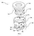
- Fig. 2 illustrating an exploded view of the flexible sealing assembly for the optical fiber draw furnace
- Fig. 3 illustrating curved ring sections and flexible dielectric ring sections for the flexible sealing assembly
- Fig. 4 illustrating movement of the curved ring sections and the flexible dielectric ring sections in the flexible sealing assembly
- Fig. 5 illustrating an example optical fiber draw furnace.
- the furnace sealing assembly 100 and its components may be composed of graphite, aluminium, steel or other suitable material or combination of materials.
- the furnace sealing assembly 100 comprises a cooling section 102, a felt holding section 104, an inlet 106, an outlet 108, a first plurality of curved ring sections 110, a second plurality of curved ring sections 112, a plurality of tension loaders 114, a plurality of apertures 116, a seal cover 118 and a plurality of flexible dielectric ring sections 120.
- the cooling section 102 may have a three-cylinder structure having a top cylindrical element 128, a middle cylindrical element 130 and a bottom cylindrical element 132.
- the top cylindrical element 128, the middle cylindrical element 130 and the bottom cylindrical element 132 are stacked and joined to form the cooling section 102.
- the cooling section 102 may comprise the inlet 106 and the outlet 108, on the top cylindrical element 128, configured for water which help in preventing heat transfer to the plurality of flexible dielectric ring sections 120.
- the top cylindrical element 128 may have an inner diameter of about 115 ⁇ 0.5mm and a height of about 64+0.5mm.
- the middle cylindrical element 130 may have an inner diameter of about 115+0.5mm, an outer diameter of 190 ⁇ 0.5mm and a height of about 23+0.5mm.
- the bottom cylindrical element 132 may have similar dimensions as the top cylindrical element 128. However, the present disclosure is not limited to these dimensions.
- the cooling section 102 may be configured for cooling a glass preform 504.
- the felt holding section 104 may be placed at a top portion of the cooling section 102.
- the felt holding section 104 may be configured to hold the plurality of flexible dielectric ring sections 120 which is further attached to the first plurality of curved ring sections 110 and the second plurality of curved ring sections 112.
- the plurality of flexible dielectric ring sections 120 is attached to the first plurality of curved ring sections 110 and the second plurality of curved ring sections 112 such that the plurality of flexible dielectric ring sections 120 presses against the glass preform 504 for sealing.
- the felt holding section 104 may have an inner diameter of about 190 ⁇ 0.5mm, an outer diameter of about 222 ⁇ 0.5mm and a height of about 78+0.5mm.
- the felt holding section 104 comprises the first plurality of curved ring sections 110 and the second plurality of curved ring sections 112 which is covered using the seal cover 118.
- the seal cover 118 may have an inner diameter of 115 ⁇ 0.5mm, an outer diameter of 222 ⁇ 0.5mm and a height of about 30 ⁇ 0.5mm.
- the first plurality of curved ring sections 110 is arranged in a circular arrangement. Further, the first plurality of curved ring sections 110 is arranged such that a central passage 122 is formed to enable entry of the glass preform 504.
- Each curved ring section 110 is defined by same radius of curvature and is placed such that a first gap 124 exists between adjacent curved ring sections (as shown in Fig. 3 ).
- the second plurality of curved ring sections 112 is arranged in a circular arrangement.
- the second plurality of curved ring sections 112 is arranged such that the central passage 122 is formed to enable entry of the glass preform 504.
- Each curved ring section 112 is defined by same radius of curvature and is placed such that a second gap 126 exists between adjacent curved ring sections .
- the second plurality of curved ring sections 112 is placed coaxially to the first plurality of curved ring sections 110 (as shown in Fig. 1 and Fig. 2 ).
- the second plurality of curved ring sections 112 is placed such that there is an offset between the first gap 124 between each curved ring section of the first plurality of curved ring sections 110 and the second gap 126 between each curved ring section of the second plurality of curved ring sections 112.
- the first plurality of curved ring sections 110 and the second plurality of curved ring sections 112 form a circular seal unit which are placed co-axially such that separating slits of the first plurality of curved ring sections 110 is placed at 30 to 70 degree offset with respect to separating slits of the second plurality of curved ring sections 112.
- each of the first plurality of curved ring sections 110 and the second plurality of curved ring sections 112 may have an inner diameter of about 140 ⁇ 0.5mm, an outer diameter of about 170+0.5mm and a height of about 25 ⁇ 0.5mm.
- each of the first plurality of curved ring sections 110 and the second plurality of curved ring sections 112 is a three-part curved ring section, which when placed offset to each other as mentioned above, provides flexibility in movement to the furnace sealing assembly 100 depending on the diameter variations.
- the offset arrangement provides flexibility in movement of the first plurality of curved ring sections 110, the second plurality of curved ring sections 112 and the plurality of flexible dielectric ring sections 120 as per the diameter variations (or preform diameter variations) at various location present along a preform length. Such movement is shown in Fig.
- each curved ring section of the first plurality of curved ring sections 110 and the second plurality of curved ring sections 112 moves between the two dashed circles (i.e., inner dashed circle and outer dashed circle).
- Each curved ring section of the first plurality of curved ring sections 110 and the second plurality of curved ring sections 112 gets adjusted by spring tension mechanism depending upon preform size variations.
- each curved ring section of the first plurality of curved ring sections 110 and the second plurality of curved ring sections 112 helps to detect the diameter variations at small intervals.
- the plurality of tension loaders 114 is secured in the plurality of apertures 116 present on the felt holding section 104 using a plurality of connecting means, such as but not limited to nut-spring, to apply spring tension mechanism.
- a plurality of connecting means such as but not limited to nut-spring
- other connecting means are known, foreseeable, and unforeseeable, and each of these is readily apparent to those of skill in the art upon reading the present disclosure.
- the plurality of tension loaders 114 is configured to exert continuous radially inward force on at least one curved ring section.
- the first plurality of curved ring sections 110 and the second plurality of curved ring sections 112, in which each curved ring is separated from each other, is radially movable such that the first plurality of curved ring sections 110 and the second plurality of curved ring sections 112 create a seal between the glass preform 504 and a vertical hollow body 506 (as shown in FIG. 5 ) in the optical fiber draw furnace 500 (as shown in FIG. 5 ) while axial movement of the glass preform 504, where diameter of the glass preform 504 may vary.
- the vertical hollow body 506 is a cylindrical hollow body that has a top end 508 and a bottom end 510, wherein the glass preform 504 is hung near the top end 508 and then is melted to form an optical fiber 502.
- the optical fiber 502 exits the vertical hollow body 506 from the bottom end 510.
- the flexible sealing assembly 100 is placed near the top end 508.
- the flexible sealing assembly 100 enables drawing of preforms having up to 18 ⁇ 10mm diameter variations due to flexibility in the movement of the plurality of flexible dielectric ring sections 120 attached to the first plurality of curved ring sections 110 and the second plurality of curved ring sections 112.
- the flexible sealing assembly 100 allows drawing of triple joint preforms without affecting furnace health due to separation of the flexible sealing assembly 100 from heat zone and thus an optical fiber with better mechanical and optical parameters can be produced.
- the flexible sealing assembly 100 incorporates easy to use spring tension mechanism, which provides required flexibility in the movement of the plurality of flexible dielectric ring sections 120 as per preform diameter variations.
- Fig. 6 is a flowchart illustrating a method of manufacturing an optical fiber in accordance with an embodiment of the present disclosure.
- the glass preform (aka “cylindrical glass preform") 504 is held near the top end 508 of the optical fiber draw furnace 500.
- the glass preform 504 is melted.
- the glass preform 504 may have a diameter greater than 80mm to form the optical fiber 502 having a diameter less than 260 microns.
- the glass preform 504 is fed into the optical fiber draw furnace 500.
- the glass preform 504 is periodically or continuously pushed into the optical fiber draw furnace 500 as lower end of the glass preform 504 is melted into the optical fiber 502 and a continuous radially inward force is exerted by the first plurality of curved ring sections 110 and the second plurality of curved ring sections 112 that create a seal between the glass preform 504 and the vertical hollow body 506.
- the first plurality of curved ring sections 110 and the second plurality of curved ring sections 112 are radially movable and each curved ring section is defined by same radius of curvature.
- Fig. 7 is a flowchart illustrating a method of manufacturing the optical fiber in accordance with another embodiment of the present disclosure.
- the glass preform (aka “cylindrical glass preform") 504 is held near the top end 508 of the optical fiber draw furnace 500.
- the glass preform 504 is melted.
- the glass preform 504 may have a diameter greater than 80mm to form the optical fiber 502 having a diameter less than 260 microns.
- the glass preform 504 is fed into the optical fiber draw furnace 500.
- the glass preform 504 is periodically or continuously pushed into the optical fiber draw furnace 500 as lower end of the glass preform 504 is melted into the optical fiber 502 and a continuous radially inward force is exerted by the first plurality of curved ring sections 110 and the second plurality of curved ring sections 112 that create a seal between the glass preform 504 and the vertical hollow body 506.
- the first plurality of curved ring sections 110 and the second plurality of curved ring sections 112 are radially movable and each curved ring section is defined by same radius of curvature.
- the optical fiber 502 is cooled.
- one or more coatings are applied on the optical fiber 502.
- the flexible sealing assembly for an optical fiber draw furnace provides a sealing assembly that can keep adjusting as per a preform diameter.
- the multiple curved ring sections help to eliminate diameter variations placed at smaller intervals along a preform length.
- the three-part curved ring section provides flexibility in movement to the furnace sealing assembly 100 depending on the diameter variations.
- the arrangement of the flexible sealing assembly 100 prevents unwanted dissipation of heat from the optical fiber draw furnace 500 which further prevents furnace health deterioration and oxidization of the plurality of flexible dielectric ring sections 120, thereby preventing preform deformities like optical fiber with uneven geometric properties.
- Disjunctive language such as the phrase "at least one of X, Y, Z," unless specifically stated otherwise, is otherwise understood with the context as used in general to present that an item, term, etc., may be either X, Y, or Z, or any combination thereof (e.g., X, Y, and/or Z). Thus, such disjunctive language is not generally intended to, and should not, imply that certain embodiments require at least one of X, at least one of Y, or at least one of Z to each be present.
Landscapes
- Engineering & Computer Science (AREA)
- Chemical & Material Sciences (AREA)
- Life Sciences & Earth Sciences (AREA)
- General Life Sciences & Earth Sciences (AREA)
- Geochemistry & Mineralogy (AREA)
- Manufacturing & Machinery (AREA)
- Materials Engineering (AREA)
- Organic Chemistry (AREA)
- Manufacture, Treatment Of Glass Fibers (AREA)
Abstract
Description
- Embodiments of the present disclosure relate to the field optical fiber draw furnace and more particularly, relates to a flexible sealing assembly for an optical fiber draw furnace and a method of manufacturing thereof.
- This application claims the benefit of
Indian Application No. 202211014403 titled "FLEXIBLE SEALING ASSEMBLY FOR OPTICAL FIBER DRAW FURNACE AND OPTICAL FIBER" filed by the applicant on 16.03.2022 - Modem optical devices and optical communications systems widely use fiber optic cables. Optical fibers are strands of glass fiber processed so that light beams transmitted through the glass fiber are subject to total internal reflection wherein a large fraction of the incident intensity of light directed into the fiber is received at the other end of the fiber.
- Within the field of optical fiber manufacturing, many techniques have been used to produce optical fiber having improved qualities such as reduced optical loss and reduced polarization mode dispersion (PMD). Deposition techniques inside a substrate tube include MCVD (Modified Chemical Vapor Deposition), FCVD (Furnace Chemical Vapor Deposition) or PCVD (Plasma Chemical Vapor Deposition).
- Many forms of optical fiber loss are attributable to geometrical deformities present in optical fiber, which often result from conventional optical fiber manufacturing processes. In general, optical fibers typically are manufactured in a draw tower by vertically suspending an optical fiber preform and moving it into a draw furnace at a controlled rate. The preform softens in the furnace and optical fiber is drawn from the softened end of the preform rod by a capstan or other appropriate device located at the base of the fiber draw tower.
- The primary preform may consist of a rod fabricated by outside deposition techniques, such as OVD (Outside Vapor Deposition) or VAD (Vapour Axial Deposition). A glass preform produced by an Outside Vapor Deposition (OVD) process has a diameter variation along its length, meaning higher the diameter of the glass preform, more is the diameter variation. To draw such glass preform having the diameter variation, there is a high probability of disturbance of sealing apparatus, due to which oxygen may enter inside an optical fiber draw furnace (i.e., furnace) that can deteriorate furnace health and affect mechanical and optical parameters of an optical fiber produced from that glass preform.
- One way to address the aforesaid drawback is using felt rings in accordance with a minimum diameter of the glass preform.
- However, the existing felt rings have limitations of flexibility and less elasticity which is not sufficient to tackle high diameter variation of glass preforms greater than 5mm. Therefore, there exists a need to develop a sealing assembly which solves the aforesaid drawbacks. The present disclosure provides an optical fiber cable with improved binding technique.
- Embodiments of the present disclosure provide an optical fiber draw furnace (500), comprising a vertical hollow body (506) having a top end (508) and a bottom end (510), a glass preform (504) is hung near the top end (508) and the glass preform (504) is melted to form an optical fiber (502), wherein the optical fiber (502) exits the vertical hollow body (506) from the bottom end (510); and a flexible sealing assembly (100) placed near the top end (508). The flexible sealing assembly (100) further includes a first plurality of curved ring sections (110) arranged in a circular arrangement and a plurality of tension loaders (114) exerting continuous radially inward force on at least one curved ring section. Each curved ring section of the first plurality of curved ring sections (110) is separated from each other. Particularly, the first plurality of curved ring sections (110) is radially movable such that the first plurality of curved ring sections (110) creates a seal between the glass preform (504) and the vertical hollow body (506) while axial movement of the glass preform (504). Moreover, diameter of the glass preform (504) varies.
- According to the first aspect of the present disclosure, the plurality of flexible dielectric ring sections (120) are attached to the first plurality of curved ring sections (110) such that the plurality of flexible dielectric ring sections (120) presses against the glass preform (504) for sealing. In particular, the first plurality of curved ring sections (110) is arranged such that a central passage (122) is formed to enable entry of the glass preform (504). Moreover, each curved ring section is placed such that a first gap (124) exists between adjacent curved ring sections.
- According to a second aspect of the present disclosure, the second plurality of curved ring sections (112) coaxial to the first plurality of curved ring sections (110). The second plurality of curved ring sections (112) is an offset between a first gap (124) between each curved ring section of the first plurality of curved ring sections (110) and a second gap (126) between each curved ring section of the second plurality of curved ring sections (112). Particularly, the offset is between 30 to 70 degrees.
- According to a third aspect of the present disclosure, a method of manufacturing an optical fiber (502) comprising steps of holding a glass preform (504) near a top end (508) of an optical fiber draw furnace (500), melting the glass preform (504) of a diameter greater than 80mm to form the optical fiber (502) having a diameter less than 260 microns; and feeding the glass preform (504) into the optical fiber draw furnace (500).
- According to a fourth aspect of the present disclosure, step of feed further comprises periodically or continuously pushing the glass preform (504) into the optical fiber draw furnace (500) as lower end of the glass preform (504) is melted into the optical fiber (502), exerting continuous radially inward force by a first plurality of curved ring sections (110),creating a seal between the glass preform (504) and a vertical hollow body (506). The first plurality of curved ring sections (110) is radially movable and each curved ring section is defined by the same radius of curvature.
- According to a fifth aspect of the present disclosure, the method further comprises cooling the optical fiber (502) and/or applying one or more coatings on the optical fiber (502).
- The foregoing solutions of the present disclosure are attained by employing an optical fiber draw furnace. These and other aspects herein will be better appreciated and understood when considered in conjunction with the following description and the accompanying drawings. It should be understood, however, that the following descriptions are given by way of illustration and not of limitation. Many changes and modifications may be made within the scope of the disclosure herein without departing from the spirit thereof.
- To describe the technical solutions in the embodiments of the present disclosure or in the prior art more clearly, the following briefly describes the accompanying drawings required for describing the embodiments or the prior art. Apparently, the accompanying drawings in the following description merely show some embodiments of the present disclosure, and a person of ordinary skill in the art can derive other implementations from these accompanying drawings without creative efforts. All of the embodiments or the implementations shall fall within the protection scope of the present disclosure.
-
Fig. 1 is a snapshot illustrating a perspective view of a flexible sealing assembly for an optical fiber draw furnace in accordance with an embodiment of the present disclosure; -
Fig. 2 is a snapshot illustrating an exploded view of the flexible sealing assembly for the optical fiber draw furnace in accordance with an embodiment of the present disclosure; -
Fig. 3 is a snapshot illustrating curved ring sections and flexible dielectric ring sections for the flexible sealing assembly in accordance with an embodiment of the present disclosure; -
Fig. 4 is a snapshot illustrating movement of the curved ring sections and the flexible dielectric ring sections in the flexible sealing assembly in accordance with embodiment of the present disclosure; -
Fig. 5 is a snapshot illustrating an example optical fiber draw furnace in accordance with an embodiment of the present disclosure; -
Fig. 6 is a flowchart illustrating a method of manufacturing an optical fiber in accordance with an embodiment of the present disclosure; -
Fig. 7 is a flowchart illustrating a method of manufacturing the optical fiber in accordance with another embodiment of the present disclosure. -
- Optical fiber draw furnace - 500
- optical fiber- 502
- glass preform- 504
- Vertical hollow body- 506
- Top end-508
- Bottom end- 510
-
Flexible sealing assembly 100 -
Cooling section 102 - Felt
holding section 104 -
Inlet 106 -
Outlet 108 - First plurality of
curved ring sections 110 - Second plurality of
curved ring sections 110 - Plurality of
tension loaders 114 - Plurality of
apertures 116 -
Seal cover 118 - Plurality of flexible
dielectric ring sections 120 -
Central passage 122 - Top
cylindrical element 128 - Middle
cylindrical element 130 - Bottom
cylindrical element 132 - The optical fiber is illustrated in the accompanying drawings, which like reference letters indicate corresponding parts in the various figures. It should be noted that the accompanying figure is intended to present illustrations of exemplary embodiments of the present disclosure. This figure is not intended to limit the scope of the present disclosure. It should also be noted that the accompanying figure is not necessarily drawn to scale.
- Those skilled in the art will be aware that the present disclosure is subject to variations and modifications other than those specifically described. It is to be understood that the present disclosure includes all such variations and modifications. The disclosure also includes all such steps, features, compositions and compounds referred to or indicated in this specification, individually or collectively, and any and all combinations of any or more of such steps or features.
- For convenience, before further description of the present disclosure, certain terms employed in the specification, and examples are collected here. These definitions should be read in the light of the remainder of the disclosure and understood as by a person of skill in the art. The terms used herein have the meanings recognized and known to those of skill in the art, however, for convenience and completeness, particular terms and their meanings are set forth below.
- The articles "a", "an" and "the" are used to refer to one or to more than one (i.e., to at least one) of the grammatical object of the article.
- The terms "comprise" and "comprising" are used in the inclusive, open sense, meaning that additional elements may be included. It is not intended to be construed as "consists of only". Throughout this specification, unless the context requires otherwise the word "comprise", and variations such as "comprises" and "comprising", will be understood to imply the inclusion of a stated element or step or group of element or steps but not the exclusion of any other element or step or group of element or steps.
- The term "including" is used to mean "including but not limited to". "Including" and "including but not limited to" are used interchangeably.
- The following brief definition of terms shall apply throughout the present disclosure:
Optical fiber refers to a medium associated with transmission of information over long distances in the form of light pulses. The optical fiber uses light to transmit voice and data communications over long distances when encapsulated in a jacket/sheath. The optical fiber may be of ITU.T G.657.A2 category. Alternatively, the optical fiber may be of ITU.T G.657.A1 or G.657.B3 or G.652.D or a multi-core or other suitable category. The optical fiber may be a bend insensitive fiber that has less degradation in optical properties or less increment in optical attenuation during multiple winding/unwinding operations of an optical fiber cable. - ITU.T, stands for International Telecommunication Union-Telecommunication Standardization Sector, is one of the three sectors of the ITU. The ITU is the United Nations specialized agency in the field of telecommunications and is responsible for studying technical, operating and tariff questions and issuing recommendations on them with a view to standardizing telecommunications on a worldwide basis.
- Now simultaneous reference is made to
Fig. 1 illustrating a perspective view of a flexible sealing assembly for an optical fiber draw furnace,Fig. 2 illustrating an exploded view of the flexible sealing assembly for the optical fiber draw furnace,Fig. 3 illustrating curved ring sections and flexible dielectric ring sections for the flexible sealing assembly,Fig. 4 illustrating movement of the curved ring sections and the flexible dielectric ring sections in the flexible sealing assembly andFig. 5 illustrating an example optical fiber draw furnace. - The
furnace sealing assembly 100 and its components may be composed of graphite, aluminium, steel or other suitable material or combination of materials. In particular, thefurnace sealing assembly 100 comprises acooling section 102, afelt holding section 104, aninlet 106, anoutlet 108, a first plurality ofcurved ring sections 110, a second plurality ofcurved ring sections 112, a plurality oftension loaders 114, a plurality ofapertures 116, aseal cover 118 and a plurality of flexibledielectric ring sections 120. - The
cooling section 102 may have a three-cylinder structure having a topcylindrical element 128, a middlecylindrical element 130 and a bottomcylindrical element 132. In particular, the topcylindrical element 128, the middlecylindrical element 130 and the bottomcylindrical element 132 are stacked and joined to form thecooling section 102. Moreover, thecooling section 102 may comprise theinlet 106 and theoutlet 108, on the topcylindrical element 128, configured for water which help in preventing heat transfer to the plurality of flexibledielectric ring sections 120. Further, the topcylindrical element 128 may have an inner diameter of about 115±0.5mm and a height of about 64+0.5mm. Similarly, the middlecylindrical element 130 may have an inner diameter of about 115+0.5mm, an outer diameter of 190±0.5mm and a height of about 23+0.5mm. The bottomcylindrical element 132 may have similar dimensions as the topcylindrical element 128. However, the present disclosure is not limited to these dimensions. - In an embodiment of the present disclosure, the
cooling section 102 may be configured for cooling aglass preform 504. - The felt holding
section 104 may be placed at a top portion of thecooling section 102. In particular, the felt holdingsection 104 may be configured to hold the plurality of flexibledielectric ring sections 120 which is further attached to the first plurality ofcurved ring sections 110 and the second plurality ofcurved ring sections 112. Moreover, the plurality of flexibledielectric ring sections 120 is attached to the first plurality ofcurved ring sections 110 and the second plurality ofcurved ring sections 112 such that the plurality of flexibledielectric ring sections 120 presses against theglass preform 504 for sealing. Further, the felt holdingsection 104 may have an inner diameter of about 190±0.5mm, an outer diameter of about 222±0.5mm and a height of about 78+0.5mm. - The felt holding
section 104 comprises the first plurality ofcurved ring sections 110 and the second plurality ofcurved ring sections 112 which is covered using theseal cover 118. Particularly, theseal cover 118 may have an inner diameter of 115±0.5mm, an outer diameter of 222±0.5mm and a height of about 30±0.5mm. Moreover, the first plurality ofcurved ring sections 110 is arranged in a circular arrangement. Further, the first plurality ofcurved ring sections 110 is arranged such that acentral passage 122 is formed to enable entry of theglass preform 504. - Each
curved ring section 110 is defined by same radius of curvature and is placed such that a first gap 124 exists between adjacent curved ring sections (as shown inFig. 3 ). Similarly, the second plurality ofcurved ring sections 112 is arranged in a circular arrangement. The second plurality ofcurved ring sections 112 is arranged such that thecentral passage 122 is formed to enable entry of theglass preform 504. Eachcurved ring section 112 is defined by same radius of curvature and is placed such that a second gap 126 exists between adjacent curved ring sections . The second plurality ofcurved ring sections 112 is placed coaxially to the first plurality of curved ring sections 110 (as shown inFig. 1 andFig. 2 ). Further, the second plurality ofcurved ring sections 112 is placed such that there is an offset between the first gap 124 between each curved ring section of the first plurality ofcurved ring sections 110 and the second gap 126 between each curved ring section of the second plurality ofcurved ring sections 112. - In accordance with an embodiment of the present disclosure, the first plurality of
curved ring sections 110 and the second plurality ofcurved ring sections 112 form a circular seal unit which are placed co-axially such that separating slits of the first plurality ofcurved ring sections 110 is placed at 30 to 70 degree offset with respect to separating slits of the second plurality ofcurved ring sections 112. - In accordance with an embodiment of the present disclosure, each of the first plurality of
curved ring sections 110 and the second plurality ofcurved ring sections 112 may have an inner diameter of about 140±0.5mm, an outer diameter of about 170+0.5mm and a height of about 25±0.5mm. - In accordance with another embodiment of the present disclosure, each of the first plurality of
curved ring sections 110 and the second plurality ofcurved ring sections 112 is a three-part curved ring section, which when placed offset to each other as mentioned above, provides flexibility in movement to thefurnace sealing assembly 100 depending on the diameter variations. The offset arrangement provides flexibility in movement of the first plurality ofcurved ring sections 110, the second plurality ofcurved ring sections 112 and the plurality of flexibledielectric ring sections 120 as per the diameter variations (or preform diameter variations) at various location present along a preform length. Such movement is shown inFig. 4 using dashed circles and line, where each curved ring section of the first plurality ofcurved ring sections 110 and the second plurality ofcurved ring sections 112 moves between the two dashed circles (i.e., inner dashed circle and outer dashed circle). - Due to absence of the offset, the diameter variations in adjacent portions of the
glass preform 504 might go uncorrected. Each curved ring section of the first plurality ofcurved ring sections 110 and the second plurality ofcurved ring sections 112 gets adjusted by spring tension mechanism depending upon preform size variations. - For example, considering large size and triple joint preforms which have diameter variations at small interval lengths, each curved ring section of the first plurality of
curved ring sections 110 and the second plurality ofcurved ring sections 112 helps to detect the diameter variations at small intervals. - The plurality of
tension loaders 114 is secured in the plurality ofapertures 116 present on the felt holdingsection 104 using a plurality of connecting means, such as but not limited to nut-spring, to apply spring tension mechanism. Of course, other connecting means are known, foreseeable, and unforeseeable, and each of these is readily apparent to those of skill in the art upon reading the present disclosure. In particular, the plurality oftension loaders 114 is configured to exert continuous radially inward force on at least one curved ring section. Due to such force, the first plurality ofcurved ring sections 110 and the second plurality ofcurved ring sections 112, in which each curved ring is separated from each other, is radially movable such that the first plurality ofcurved ring sections 110 and the second plurality ofcurved ring sections 112 create a seal between theglass preform 504 and a vertical hollow body 506 (as shown inFIG. 5 ) in the optical fiber draw furnace 500 (as shown inFIG. 5 ) while axial movement of theglass preform 504, where diameter of theglass preform 504 may vary. - The vertical
hollow body 506 is a cylindrical hollow body that has atop end 508 and abottom end 510, wherein theglass preform 504 is hung near thetop end 508 and then is melted to form anoptical fiber 502. Theoptical fiber 502 exits the verticalhollow body 506 from thebottom end 510. Theflexible sealing assembly 100 is placed near thetop end 508. - The
flexible sealing assembly 100 enables drawing of preforms having up to 18±10mm diameter variations due to flexibility in the movement of the plurality of flexibledielectric ring sections 120 attached to the first plurality ofcurved ring sections 110 and the second plurality ofcurved ring sections 112. Theflexible sealing assembly 100 allows drawing of triple joint preforms without affecting furnace health due to separation of theflexible sealing assembly 100 from heat zone and thus an optical fiber with better mechanical and optical parameters can be produced. Unlike conventional complicated compressor assemblies, theflexible sealing assembly 100 incorporates easy to use spring tension mechanism, which provides required flexibility in the movement of the plurality of flexibledielectric ring sections 120 as per preform diameter variations. -
Fig. 6 is a flowchart illustrating a method of manufacturing an optical fiber in accordance with an embodiment of the present disclosure. - At
step 602, the glass preform (aka "cylindrical glass preform") 504 is held near thetop end 508 of the opticalfiber draw furnace 500. - At
step 604, theglass preform 504 is melted. Particularly, theglass preform 504 may have a diameter greater than 80mm to form theoptical fiber 502 having a diameter less than 260 microns. - At
step 606, theglass preform 504 is fed into the opticalfiber draw furnace 500. During the feeding step, theglass preform 504 is periodically or continuously pushed into the opticalfiber draw furnace 500 as lower end of theglass preform 504 is melted into theoptical fiber 502 and a continuous radially inward force is exerted by the first plurality ofcurved ring sections 110 and the second plurality ofcurved ring sections 112 that create a seal between theglass preform 504 and the verticalhollow body 506. Particularly, the first plurality ofcurved ring sections 110 and the second plurality ofcurved ring sections 112 are radially movable and each curved ring section is defined by same radius of curvature. -
Fig. 7 is a flowchart illustrating a method of manufacturing the optical fiber in accordance with another embodiment of the present disclosure. - At
step 702, the glass preform (aka "cylindrical glass preform") 504 is held near thetop end 508 of the opticalfiber draw furnace 500. - At
step 704, theglass preform 504 is melted. Particularly, theglass preform 504 may have a diameter greater than 80mm to form theoptical fiber 502 having a diameter less than 260 microns. - At
step 706, theglass preform 504 is fed into the opticalfiber draw furnace 500. During the feeding step, theglass preform 504 is periodically or continuously pushed into the opticalfiber draw furnace 500 as lower end of theglass preform 504 is melted into theoptical fiber 502 and a continuous radially inward force is exerted by the first plurality ofcurved ring sections 110 and the second plurality ofcurved ring sections 112 that create a seal between theglass preform 504 and the verticalhollow body 506. The first plurality ofcurved ring sections 110 and the second plurality ofcurved ring sections 112 are radially movable and each curved ring section is defined by same radius of curvature. - At
step 708, theoptical fiber 502 is cooled. - At
step 710, one or more coatings are applied on theoptical fiber 502. - It may be noted that the flow-
chart chart - Advantageously, the flexible sealing assembly for an optical fiber draw furnace provides a sealing assembly that can keep adjusting as per a preform diameter. The multiple curved ring sections help to eliminate diameter variations placed at smaller intervals along a preform length. The three-part curved ring section provides flexibility in movement to the
furnace sealing assembly 100 depending on the diameter variations. The arrangement of theflexible sealing assembly 100 prevents unwanted dissipation of heat from the opticalfiber draw furnace 500 which further prevents furnace health deterioration and oxidization of the plurality of flexibledielectric ring sections 120, thereby preventing preform deformities like optical fiber with uneven geometric properties. - A person of ordinary skill in the art may be aware that, in combination with the examples described in the embodiments disclosed in this specification, units and algorithm steps may be implemented by electronic hardware, computer software, or a combination thereof.
- The foregoing descriptions of specific embodiments of the present technology have been presented for purposes of illustration and description. They are not intended to be exhaustive or to limit the present technology to the precise forms disclosed, and obviously many modifications and variations are possible in light of the above teaching. The embodiments were chosen and described in order to best explain the principles of the present technology and its practical application, to thereby enable others skilled in the art to best utilize the present technology and various embodiments with various modifications as are suited to the particular use contemplated. It is understood that various omissions and substitutions of equivalents are contemplated as circumstance may suggest or render expedient, but such are intended to cover the application or implementation without departing from the spirit or scope of the claims of the present technology.
- Disjunctive language such as the phrase "at least one of X, Y, Z," unless specifically stated otherwise, is otherwise understood with the context as used in general to present that an item, term, etc., may be either X, Y, or Z, or any combination thereof (e.g., X, Y, and/or Z). Thus, such disjunctive language is not generally intended to, and should not, imply that certain embodiments require at least one of X, at least one of Y, or at least one of Z to each be present.
- In a case that no conflict occurs, the embodiments in the present disclosure and the features in the embodiments may be mutually combined. The foregoing descriptions are merely specific implementations of the present disclosure, but are not intended to limit the protection scope of the present disclosure. Any variation or replacement readily figured out by a person skilled in the art within the technical scope disclosed in the present disclosure shall fall within the protection scope of the present disclosure. Therefore, the protection scope of the present disclosure shall be subject to the protection scope of the claims.
Claims (15)
- An optical fiber draw furnace (500) characterized in that:a vertical hollow body (506) having a top end (508) and a bottom end (510), wherein a glass preform (504) is hung near the top end (508), wherein the glass preform (504) is melted to form an optical fiber (502), wherein the optical fiber (502) exits the vertical hollow body (506) from the bottom end (510); anda flexible sealing assembly (100) placed near the top end (508), the flexible sealing assembly (100) comprising:a first plurality of curved ring sections (110) arranged in a circular arrangement, wherein each curved ring section is defined by same radius of curvature; anda plurality of tension loaders (114) exerting continuous radially inward force on at least one curved ring section, wherein each curved ring section of the first plurality of curved ring sections (110) is separated from each other, wherein the first plurality of curved ring sections (110) is radially movable such that the first plurality of curved ring sections (110) creates a seal between the glass preform (504) and the vertical hollow body (506) while axial movement of the glass preform (504), where diameter of the glass preform (504) varies.
- The optical fiber draw furnace (500) as claimed in claim 1, wherein a plurality of flexible dielectric ring sections (120) attached to the first plurality of curved ring sections (110) such that the plurality of flexible dielectric ring sections (120) presses against the glass preform (504) for sealing.
- The optical fiber draw furnace (500) as claimed in claim 1, wherein the first plurality of curved ring sections (110) is arranged such that a central passage (122) is formed to enable entry of the glass preform (504).
- The optical fiber draw furnace (500) as claimed in claim 1, wherein each curved ring section is placed such that a first gap (124) exists between adjacent curved ring sections.
- The optical fiber draw furnace (500) as claimed in claim 1, wherein a second plurality of curved ring sections (112) coaxial to the first plurality of curved ring sections (110).
- The optical fiber draw furnace (500) as claimed in claim 1, wherein a second plurality of curved ring sections (112) such that there is an offset between a first gap (124) between each curved ring section of the first plurality of curved ring sections (110).
- The optical fiber draw furnace (500) as claimed in claim 1, wherein there is an offset between a second gap (126) between each curved ring section of the second plurality of curved ring sections (112).
- The optical fiber draw furnace (500) as claimed in claim 5, wherein the offset is between 30 to 70 degrees.
- An optical fiber (502) manufactured by any of claims 1 to 8.
- A method of manufacturing an optical fiber (502), characterized in that steps of:holding a glass preform (504) near a top end (508) of an optical fiber draw furnace (500);melting the glass preform (504) of a diameter greater than 80mm to form the optical fiber (502) having a diameter less than 260 microns; andfeeding the glass preform (504) into the optical fiber draw furnace (500), comprising:periodically or continuously pushing the glass preform (504) into the optical fiber draw furnace (500) as lower end of the glass preform (504) is melted into the optical fiber (502); andexerting continuous radially inward force by a first plurality of curved ring sections (110) creating a seal between the glass preform (504) and a vertical hollow body (506),wherein the first plurality of curved ring sections (110) is radially movable and each curved ring section is defined by same radius of curvature.
- The method as claimed in claim 10, wherein the method further comprising cooling the optical fiber (502).
- The method as claimed in claim 10, wherein the method further comprising applying one or more coatings on the optical fiber (502).
- The method as claimed in claim 10, wherein the first plurality of curved ring sections (110) is radially movable such that the first plurality of curved ring sections (110) creates a seal between the glass preform (504) and the vertical hollow body (506) while axial movement of the glass preform (504), where diameter of the glass preform (504) varies.
- The method as claimed in claim 10, wherein a plurality of flexible dielectric ring sections (120) attached to the first plurality of curved ring sections (110) such that the plurality of flexible dielectric ring sections (120) presses against the glass preform (504) for sealing.
- The method as claimed in claim 10, wherein the first plurality of curved ring sections (110) is arranged such that a central passage (122) is formed to enable entry of the glass preform (504).
Applications Claiming Priority (1)
| Application Number | Priority Date | Filing Date | Title |
|---|---|---|---|
| IN202211014403 | 2022-03-16 |
Publications (1)
| Publication Number | Publication Date |
|---|---|
| EP4245732A1 true EP4245732A1 (en) | 2023-09-20 |
Family
ID=85704045
Family Applications (1)
| Application Number | Title | Priority Date | Filing Date |
|---|---|---|---|
| EP23000038.2A Pending EP4245732A1 (en) | 2022-03-16 | 2023-03-10 | Flexible sealing assembly for optical fiber draw furnace and optical fiber |
Country Status (2)
| Country | Link |
|---|---|
| US (1) | US12479752B2 (en) |
| EP (1) | EP4245732A1 (en) |
Citations (2)
| Publication number | Priority date | Publication date | Assignee | Title |
|---|---|---|---|---|
| WO2014032476A1 (en) * | 2012-08-28 | 2014-03-06 | 长飞光纤光缆有限公司 | Wiredrawing method and apparatus for outer diameter fluctuation optical fiber preform |
| US20150321944A1 (en) * | 2013-01-24 | 2015-11-12 | Sumitomo Electric Industries, Ltd. | Seal structure of optical fiber drawing furnace, and method for drawing optical fiber |
Family Cites Families (2)
| Publication number | Priority date | Publication date | Assignee | Title |
|---|---|---|---|---|
| JP2013010657A (en) * | 2011-06-29 | 2013-01-17 | Sumitomo Electric Ind Ltd | Seal structure for optical fiber drawing furnace |
| CN113336434A (en) * | 2021-05-20 | 2021-09-03 | 威海威信光纤科技有限公司 | Optical fiber drawing furnace capable of automatically adjusting size of sealing device |
-
2023
- 2023-03-01 US US18/176,539 patent/US12479752B2/en active Active
- 2023-03-10 EP EP23000038.2A patent/EP4245732A1/en active Pending
Patent Citations (2)
| Publication number | Priority date | Publication date | Assignee | Title |
|---|---|---|---|---|
| WO2014032476A1 (en) * | 2012-08-28 | 2014-03-06 | 长飞光纤光缆有限公司 | Wiredrawing method and apparatus for outer diameter fluctuation optical fiber preform |
| US20150321944A1 (en) * | 2013-01-24 | 2015-11-12 | Sumitomo Electric Industries, Ltd. | Seal structure of optical fiber drawing furnace, and method for drawing optical fiber |
Also Published As
| Publication number | Publication date |
|---|---|
| US12479752B2 (en) | 2025-11-25 |
| US20230295033A1 (en) | 2023-09-21 |
Similar Documents
| Publication | Publication Date | Title |
|---|---|---|
| US5894537A (en) | Dispersion managed optical waveguide | |
| US8340488B2 (en) | Multimode optical fiber | |
| AU628719B2 (en) | Optical fiber having enhanced bend resistance | |
| US12032203B2 (en) | Reduced diameter optical fibre | |
| US8639079B2 (en) | Multimode optical fiber | |
| US8798424B2 (en) | Single-mode optical fiber | |
| EP0737873A2 (en) | Dispersion managed optical waveguide | |
| US9869814B2 (en) | Hybrid single-mode and multimode optical fiber | |
| US20110229101A1 (en) | Single-Mode Optical Fiber | |
| US20100040336A1 (en) | Multimode Fiber With At Least Dual Cladding | |
| CN111033334B (en) | Low bend loss optical fiber with chlorine doped core and offset grooves | |
| CN108474905A (en) | Hollow Core Fiber and Laser Systems | |
| CN101891380A (en) | A kind of manufacturing method of large-size optical fiber preform rod and its optical fiber | |
| JP2014506682A (en) | Multi-core optical fiber (deformation) | |
| JPH08208259A (en) | Optical fiber preform having radial change in thermal conductivity and manufacturing method thereof | |
| EP2781941A1 (en) | Optical fiber and optical transmission system | |
| EP3535610B1 (en) | Coupled few mode fibers, and corresponding optical link and optical system | |
| JP2011526879A5 (en) | Method for forming a bending-resistant optical fiber | |
| EP3745170A1 (en) | Multicore fiber and method of manufacture therefor | |
| US6990277B2 (en) | Enhanced multimode fiber | |
| EP3918386A1 (en) | Ultra-low loss optical fiber | |
| JP2008026903A (en) | Optical fiber with extended bandwidth for crimp and cleave connector | |
| US12479752B2 (en) | Flexible sealing assembly for optical fiber draw furnace and optical fiber | |
| EP3816686A2 (en) | Ultra reduced diameter optical fibre | |
| US12474521B2 (en) | Optical fibers with improved bend performance and manufacturing method thereof |
Legal Events
| Date | Code | Title | Description |
|---|---|---|---|
| PUAI | Public reference made under article 153(3) epc to a published international application that has entered the european phase |
Free format text: ORIGINAL CODE: 0009012 |
|
| STAA | Information on the status of an ep patent application or granted ep patent |
Free format text: STATUS: THE APPLICATION HAS BEEN PUBLISHED |
|
| AK | Designated contracting states |
Kind code of ref document: A1 Designated state(s): AL AT BE BG CH CY CZ DE DK EE ES FI FR GB GR HR HU IE IS IT LI LT LU LV MC ME MK MT NL NO PL PT RO RS SE SI SK SM TR |
|
| STAA | Information on the status of an ep patent application or granted ep patent |
Free format text: STATUS: REQUEST FOR EXAMINATION WAS MADE |
|
| 17P | Request for examination filed |
Effective date: 20240314 |
|
| RBV | Designated contracting states (corrected) |
Designated state(s): AL AT BE BG CH CY CZ DE DK EE ES FI FR GB GR HR HU IE IS IT LI LT LU LV MC ME MK MT NL NO PL PT RO RS SE SI SK SM TR |