EP4245666A1 - Ground support equipment - Google Patents
Ground support equipment Download PDFInfo
- Publication number
- EP4245666A1 EP4245666A1 EP22163071.8A EP22163071A EP4245666A1 EP 4245666 A1 EP4245666 A1 EP 4245666A1 EP 22163071 A EP22163071 A EP 22163071A EP 4245666 A1 EP4245666 A1 EP 4245666A1
- Authority
- EP
- European Patent Office
- Prior art keywords
- power
- support equipment
- ground support
- solid state
- aircraft
- Prior art date
- Legal status (The legal status is an assumption and is not a legal conclusion. Google has not performed a legal analysis and makes no representation as to the accuracy of the status listed.)
- Granted
Links
Images




Classifications
-
- H—ELECTRICITY
- H02—GENERATION; CONVERSION OR DISTRIBUTION OF ELECTRIC POWER
- H02J—ELECTRIC POWER NETWORKS; CIRCUIT ARRANGEMENTS OR SYSTEMS FOR SUPPLYING OR DISTRIBUTING ELECTRIC POWER; SYSTEMS FOR STORING ELECTRIC ENERGY
- H02J7/00—Circuit arrangements for charging or discharging batteries or for supplying loads from batteries
- H02J7/40—Circuit arrangements for charging or discharging batteries or for supplying loads from batteries characterised by the exchange of charge or discharge related data
- H02J7/44—Circuit arrangements for charging or discharging batteries or for supplying loads from batteries characterised by the exchange of charge or discharge related data between battery management systems and power sources
-
- B—PERFORMING OPERATIONS; TRANSPORTING
- B64—AIRCRAFT; AVIATION; COSMONAUTICS
- B64F—GROUND OR AIRCRAFT-CARRIER-DECK INSTALLATIONS SPECIALLY ADAPTED FOR USE IN CONNECTION WITH AIRCRAFT; DESIGNING, MANUFACTURING, ASSEMBLING, CLEANING, MAINTAINING OR REPAIRING AIRCRAFT, NOT OTHERWISE PROVIDED FOR; HANDLING, TRANSPORTING, TESTING OR INSPECTING AIRCRAFT COMPONENTS, NOT OTHERWISE PROVIDED FOR
- B64F1/00—Ground or aircraft-carrier-deck installations
- B64F1/35—Ground or aircraft-carrier-deck installations for supplying electrical power to stationary aircraft
-
- B—PERFORMING OPERATIONS; TRANSPORTING
- B60—VEHICLES IN GENERAL
- B60L—PROPULSION OF ELECTRICALLY-PROPELLED VEHICLES; SUPPLYING ELECTRIC POWER FOR AUXILIARY EQUIPMENT OF ELECTRICALLY-PROPELLED VEHICLES; ELECTRODYNAMIC BRAKE SYSTEMS FOR VEHICLES IN GENERAL; MAGNETIC SUSPENSION OR LEVITATION FOR VEHICLES; MONITORING OPERATING VARIABLES OF ELECTRICALLY-PROPELLED VEHICLES; ELECTRIC SAFETY DEVICES FOR ELECTRICALLY-PROPELLED VEHICLES
- B60L53/00—Methods of charging batteries, specially adapted for electric vehicles; Charging stations or on-board charging equipment therefor; Exchange of energy storage elements in electric vehicles
- B60L53/50—Charging stations characterised by energy-storage or power-generation means
- B60L53/53—Batteries
-
- B—PERFORMING OPERATIONS; TRANSPORTING
- B60—VEHICLES IN GENERAL
- B60L—PROPULSION OF ELECTRICALLY-PROPELLED VEHICLES; SUPPLYING ELECTRIC POWER FOR AUXILIARY EQUIPMENT OF ELECTRICALLY-PROPELLED VEHICLES; ELECTRODYNAMIC BRAKE SYSTEMS FOR VEHICLES IN GENERAL; MAGNETIC SUSPENSION OR LEVITATION FOR VEHICLES; MONITORING OPERATING VARIABLES OF ELECTRICALLY-PROPELLED VEHICLES; ELECTRIC SAFETY DEVICES FOR ELECTRICALLY-PROPELLED VEHICLES
- B60L53/00—Methods of charging batteries, specially adapted for electric vehicles; Charging stations or on-board charging equipment therefor; Exchange of energy storage elements in electric vehicles
- B60L53/60—Monitoring or controlling charging stations
-
- B—PERFORMING OPERATIONS; TRANSPORTING
- B64—AIRCRAFT; AVIATION; COSMONAUTICS
- B64D—EQUIPMENT FOR FITTING IN OR TO AIRCRAFT; FLIGHT SUITS; PARACHUTES; ARRANGEMENT OR MOUNTING OF POWER PLANTS OR PROPULSION TRANSMISSIONS IN AIRCRAFT
- B64D33/00—Arrangement in aircraft of power plant parts or auxiliaries not otherwise provided for
-
- B—PERFORMING OPERATIONS; TRANSPORTING
- B64—AIRCRAFT; AVIATION; COSMONAUTICS
- B64F—GROUND OR AIRCRAFT-CARRIER-DECK INSTALLATIONS SPECIALLY ADAPTED FOR USE IN CONNECTION WITH AIRCRAFT; DESIGNING, MANUFACTURING, ASSEMBLING, CLEANING, MAINTAINING OR REPAIRING AIRCRAFT, NOT OTHERWISE PROVIDED FOR; HANDLING, TRANSPORTING, TESTING OR INSPECTING AIRCRAFT COMPONENTS, NOT OTHERWISE PROVIDED FOR
- B64F1/00—Ground or aircraft-carrier-deck installations
-
- B—PERFORMING OPERATIONS; TRANSPORTING
- B64—AIRCRAFT; AVIATION; COSMONAUTICS
- B64F—GROUND OR AIRCRAFT-CARRIER-DECK INSTALLATIONS SPECIALLY ADAPTED FOR USE IN CONNECTION WITH AIRCRAFT; DESIGNING, MANUFACTURING, ASSEMBLING, CLEANING, MAINTAINING OR REPAIRING AIRCRAFT, NOT OTHERWISE PROVIDED FOR; HANDLING, TRANSPORTING, TESTING OR INSPECTING AIRCRAFT COMPONENTS, NOT OTHERWISE PROVIDED FOR
- B64F1/00—Ground or aircraft-carrier-deck installations
- B64F1/35—Ground or aircraft-carrier-deck installations for supplying electrical power to stationary aircraft
- B64F1/352—Mobile units
-
- B—PERFORMING OPERATIONS; TRANSPORTING
- B64—AIRCRAFT; AVIATION; COSMONAUTICS
- B64U—UNMANNED AERIAL VEHICLES [UAV]; EQUIPMENT THEREFOR
- B64U50/00—Propulsion; Power supply
- B64U50/30—Supply or distribution of electrical power
- B64U50/37—Charging when not in flight
-
- B—PERFORMING OPERATIONS; TRANSPORTING
- B64—AIRCRAFT; AVIATION; COSMONAUTICS
- B64U—UNMANNED AERIAL VEHICLES [UAV]; EQUIPMENT THEREFOR
- B64U50/00—Propulsion; Power supply
- B64U50/30—Supply or distribution of electrical power
- B64U50/37—Charging when not in flight
- B64U50/38—Charging when not in flight by wireless transmission
-
- H—ELECTRICITY
- H02—GENERATION; CONVERSION OR DISTRIBUTION OF ELECTRIC POWER
- H02J—ELECTRIC POWER NETWORKS; CIRCUIT ARRANGEMENTS OR SYSTEMS FOR SUPPLYING OR DISTRIBUTING ELECTRIC POWER; SYSTEMS FOR STORING ELECTRIC ENERGY
- H02J1/00—Circuit arrangements for DC mains or DC distribution networks
- H02J1/14—Balancing load and power generation in DC networks
-
- H—ELECTRICITY
- H02—GENERATION; CONVERSION OR DISTRIBUTION OF ELECTRIC POWER
- H02J—ELECTRIC POWER NETWORKS; CIRCUIT ARRANGEMENTS OR SYSTEMS FOR SUPPLYING OR DISTRIBUTING ELECTRIC POWER; SYSTEMS FOR STORING ELECTRIC ENERGY
- H02J7/00—Circuit arrangements for charging or discharging batteries or for supplying loads from batteries
- H02J7/02—Circuit arrangements for charging or discharging batteries or for supplying loads from batteries for charging batteries from AC mains by converters
-
- H—ELECTRICITY
- H02—GENERATION; CONVERSION OR DISTRIBUTION OF ELECTRIC POWER
- H02J—ELECTRIC POWER NETWORKS; CIRCUIT ARRANGEMENTS OR SYSTEMS FOR SUPPLYING OR DISTRIBUTING ELECTRIC POWER; SYSTEMS FOR STORING ELECTRIC ENERGY
- H02J7/00—Circuit arrangements for charging or discharging batteries or for supplying loads from batteries
- H02J7/80—Circuit arrangements for charging or discharging batteries or for supplying loads from batteries including monitoring or indicating arrangements
-
- H—ELECTRICITY
- H02—GENERATION; CONVERSION OR DISTRIBUTION OF ELECTRIC POWER
- H02J—ELECTRIC POWER NETWORKS; CIRCUIT ARRANGEMENTS OR SYSTEMS FOR SUPPLYING OR DISTRIBUTING ELECTRIC POWER; SYSTEMS FOR STORING ELECTRIC ENERGY
- H02J7/00—Circuit arrangements for charging or discharging batteries or for supplying loads from batteries
- H02J7/855—Circuit arrangements for charging or discharging batteries or for supplying loads from batteries with circuits adapted for supplying loads from the battery
-
- H—ELECTRICITY
- H02—GENERATION; CONVERSION OR DISTRIBUTION OF ELECTRIC POWER
- H02J—ELECTRIC POWER NETWORKS; CIRCUIT ARRANGEMENTS OR SYSTEMS FOR SUPPLYING OR DISTRIBUTING ELECTRIC POWER; SYSTEMS FOR STORING ELECTRIC ENERGY
- H02J7/00—Circuit arrangements for charging or discharging batteries or for supplying loads from batteries
- H02J7/865—Battery or charger load switching, e.g. concurrent charging and load supply
-
- H—ELECTRICITY
- H02—GENERATION; CONVERSION OR DISTRIBUTION OF ELECTRIC POWER
- H02J—ELECTRIC POWER NETWORKS; CIRCUIT ARRANGEMENTS OR SYSTEMS FOR SUPPLYING OR DISTRIBUTING ELECTRIC POWER; SYSTEMS FOR STORING ELECTRIC ENERGY
- H02J7/00—Circuit arrangements for charging or discharging batteries or for supplying loads from batteries
- H02J7/90—Regulation of charging or discharging current or voltage
- H02J7/933—Regulation of charging or discharging current or voltage the cycle being controlled or terminated in response to electric parameters
-
- B—PERFORMING OPERATIONS; TRANSPORTING
- B60—VEHICLES IN GENERAL
- B60L—PROPULSION OF ELECTRICALLY-PROPELLED VEHICLES; SUPPLYING ELECTRIC POWER FOR AUXILIARY EQUIPMENT OF ELECTRICALLY-PROPELLED VEHICLES; ELECTRODYNAMIC BRAKE SYSTEMS FOR VEHICLES IN GENERAL; MAGNETIC SUSPENSION OR LEVITATION FOR VEHICLES; MONITORING OPERATING VARIABLES OF ELECTRICALLY-PROPELLED VEHICLES; ELECTRIC SAFETY DEVICES FOR ELECTRICALLY-PROPELLED VEHICLES
- B60L2200/00—Type of vehicles
-
- H—ELECTRICITY
- H02—GENERATION; CONVERSION OR DISTRIBUTION OF ELECTRIC POWER
- H02J—ELECTRIC POWER NETWORKS; CIRCUIT ARRANGEMENTS OR SYSTEMS FOR SUPPLYING OR DISTRIBUTING ELECTRIC POWER; SYSTEMS FOR STORING ELECTRIC ENERGY
- H02J2105/00—Networks for supplying or distributing electric power characterised by their spatial reach or by the load
- H02J2105/50—Networks for supplying or distributing electric power characterised by their spatial reach or by the load for selectively controlling the operation of the loads
- H02J2105/52—Networks for supplying or distributing electric power characterised by their spatial reach or by the load for selectively controlling the operation of the loads for limitation of the power consumption in the networks or in one section of the networks, e.g. load shedding or peak shaving
- H02J2105/53—Networks for supplying or distributing electric power characterised by their spatial reach or by the load for selectively controlling the operation of the loads for limitation of the power consumption in the networks or in one section of the networks, e.g. load shedding or peak shaving for partial power limitation, e.g. entering degraded or current limitation modes
-
- H—ELECTRICITY
- H02—GENERATION; CONVERSION OR DISTRIBUTION OF ELECTRIC POWER
- H02J—ELECTRIC POWER NETWORKS; CIRCUIT ARRANGEMENTS OR SYSTEMS FOR SUPPLYING OR DISTRIBUTING ELECTRIC POWER; SYSTEMS FOR STORING ELECTRIC ENERGY
- H02J2207/00—Details of circuit arrangements for charging or discharging batteries or supplying loads from batteries
- H02J2207/20—Charging or discharging characterised by the power electronics converter
-
- H—ELECTRICITY
- H02—GENERATION; CONVERSION OR DISTRIBUTION OF ELECTRIC POWER
- H02J—ELECTRIC POWER NETWORKS; CIRCUIT ARRANGEMENTS OR SYSTEMS FOR SUPPLYING OR DISTRIBUTING ELECTRIC POWER; SYSTEMS FOR STORING ELECTRIC ENERGY
- H02J2207/00—Details of circuit arrangements for charging or discharging batteries or supplying loads from batteries
- H02J2207/30—Charge provided using DC bus or data bus of a computer
-
- Y—GENERAL TAGGING OF NEW TECHNOLOGICAL DEVELOPMENTS; GENERAL TAGGING OF CROSS-SECTIONAL TECHNOLOGIES SPANNING OVER SEVERAL SECTIONS OF THE IPC; TECHNICAL SUBJECTS COVERED BY FORMER USPC CROSS-REFERENCE ART COLLECTIONS [XRACs] AND DIGESTS
- Y02—TECHNOLOGIES OR APPLICATIONS FOR MITIGATION OR ADAPTATION AGAINST CLIMATE CHANGE
- Y02T—CLIMATE CHANGE MITIGATION TECHNOLOGIES RELATED TO TRANSPORTATION
- Y02T10/00—Road transport of goods or passengers
- Y02T10/60—Other road transportation technologies with climate change mitigation effect
- Y02T10/70—Energy storage systems for electromobility, e.g. batteries
-
- Y—GENERAL TAGGING OF NEW TECHNOLOGICAL DEVELOPMENTS; GENERAL TAGGING OF CROSS-SECTIONAL TECHNOLOGIES SPANNING OVER SEVERAL SECTIONS OF THE IPC; TECHNICAL SUBJECTS COVERED BY FORMER USPC CROSS-REFERENCE ART COLLECTIONS [XRACs] AND DIGESTS
- Y02—TECHNOLOGIES OR APPLICATIONS FOR MITIGATION OR ADAPTATION AGAINST CLIMATE CHANGE
- Y02T—CLIMATE CHANGE MITIGATION TECHNOLOGIES RELATED TO TRANSPORTATION
- Y02T10/00—Road transport of goods or passengers
- Y02T10/60—Other road transportation technologies with climate change mitigation effect
- Y02T10/7072—Electromobility specific charging systems or methods for batteries, ultracapacitors, supercapacitors or double-layer capacitors
Definitions
- This invention relates to a ground support equipment.
- the present invention relates to a ground support equipment for powering an aircraft on the ground.
- Airports have ground support equipment, such as ground power units, for powering aircraft when parked next to an airport building.
- This ground-based power supply allows the electronic systems of the aircraft to remain on without needing the aircraft engines to be running which would require additional aviation fuel.
- Airports also have a number of powered and non-powered equipment on the tarmac which provide various functions.
- Powered equipment such as refuelers, tugs, eGPUs and buses, are required periodically throughout the day to move fuel, aircraft and passengers.
- one barrier to wider adoption of electrifying these vehicles is a lack of battery charging capacity at airports.
- the present invention seeks to address at least some of these issues.
- the present invention provides a ground support equipment for powering an aircraft on the ground, the ground support equipment comprising: a solid state converter configured to power an aircraft on the ground from an airport power source having a pre-determined maximum power, and a battery charging unit configured to charge an external battery from the airport power source.
- the solid state converter is configured to measure an instantaneous power drawn by the aircraft.
- the solid state converter is configured to generate, for controlling the battery charging unit, a control signal indicative of a maximum power available for the battery charging unit based on the difference between the pre-determined maximum power of the airport power source and the instantaneous power drawn by the aircraft.
- the present invention provides a ground support equipment which can function as a ground power unit for powering an aircraft on the ground and divert any excess power to a charging port for charging a battery of an electric vehicle at the same time.
- the battery of different ground handling equipment or vehicles can be charged when the aircraft does not require the maximum power from the ground support equipment, or when the aircraft does not need powering, such as at night or when no aircraft is present at the gate.
- the solid state converter includes a controller for monitoring the power drawn by the aircraft, the present invention does away with the need for additional power controllers to determine how much power can be diverted to the charging port.
- a further advantage of the present ground support equipment is to utilise the same, either a new or existing, airport power source to power the aircraft's equipment as well as mobile battery powered equipment close to where they are used. This is in contrast to providing double the power infrastructure to power the charging port which would add significant costs to the airport.
- the solid state converter controller and the battery charging unit controller may be operatively connected to one another. This provides a communication channel between the solid state converter controller and the battery charging unit controller so that the battery charging unit controller can receive the control signal from the solid state converter controller.
- the battery charging unit can therefore provide power to the charging port in a manner that is limited based on the power drawn by the aircraft and based on the known maximum power output of the airport power supply.
- the airport power supply has a known power output (i.e. the maximum power output for the airport power supply is pre-determined or pre-set for the airport)
- the ground support equipment can be pre-set or pre-programmed or manually set to work with the known airport power supply. As such, the present ground support equipment does not have a separate transducer to measure the total power being drawn by the ground support equipment to determine how much power can be drawn by the battery charging unit.
- the solid state converter may be configured to receive a user input for setting the pre-determined maximum power.
- a ground operator can easily set or adjust the pre-determined maximum power level at the gate based on the requirements of the aircraft and/or based on the known output of the airport power supply.
- the control signal may be based on the difference between the pre-determined maximum power level and the current power level drawn by the aircraft.
- the power to the battery charging unit is reduced as power to the aircraft is required. This advantageously reduces the risk of any components being overloaded when there is a high power demand of the aircraft.
- the battery charging unit may comprise a plurality of power modules configured to receive power from the airport power source.
- the plurality of power charging modules may be connected in parallel.
- At least one of the plurality of power charging modules may be configured to provide a 30kW output.
- At least one of the plurality of charging modules is configured to convert an AC input to a DC output.
- the battery charging unit may be configured to provide a DC power output.
- the DC power output is a high voltage output.
- the ground support equipment may comprise a common rectifier configured to convert an AC input to a DC output.
- the DC bus may be configured to provide power to each of the plurality of power charging modules.
- the solid state converter may be configured to provide a 400Hz output.
- the solid state converter may be configured to receive power from an AC power source.
- the solid state converter may be configured to provide up to 180kW output power.
- the solid state converter may be pre-fused.
- the battery charging unit may be configured to provide an output power of 120kW.
- the battery charging unit may be configured to provide a DC power output.
- the ground support equipment may comprise a plurality of solid state converters configured to provide power to the aircraft.
- the plurality of solid state converters may be connected in parallel.
- ground support equipment 20 An exemplary ground support equipment 20 is shown in Figure 1 .
- the ground support equipment 20 will typically be installed as a fixed unit on the ground close to where an aircraft will be parked on the ground.
- the ground support equipment 20 has a cabinet 40 having a first side 42 of the ground support equipment includes a user interface 9 for a charging port shown in Figure 1 connected to a CCS2 connector 8.
- a charging port shown in Figure 1 connected to a CCS2 connector 8.
- the charging port may be configured to connect to a CCS2 connector as shown in Figures 1 to 4 or to a CHAdeMO connector.
- the CCS2 and CHAdeMO connectors are both able to provide DC charging. It would be apparent that these were merely exemplary connectors and that other connectors could be suitable for use with the present ground support equipment.
- FIG. 2 illustrates a panel of the first side 42 removed to show an exemplary electrical circuit of a charging unit which provides the battery charging functionality described herein.
- a charger control unit 1 is operatively connected to four 30kW charging modules 2.
- the charging modules 2 may be any of the charging modules 70, 72 explained below with reference to Figures 5 to 9 .
- a moulded case circuit breaker (MCCB) 3 is provided to provide overload protection to the electrical circuit.
- a charger input contactor 4 is provided adjacent to an Earth leakage supervision relay 5.
- Two DC fuses 6 with respective DC contactors 7 provide output power for the connector 8.
- a battery (not shown) of a ground support equipment or vehicle can thus be charged via the connector 8.
- a ground power unit (GPU) section for powering the aircraft as shown in Figures 3 and 4 .
- the second side 44 of the cabinet 40 has a user interface 16 for the GPU section.
- Within the cabinet 40 there is an input breaker 10, an output contactor 11 and an auxiliary power supply 12 for powering the aircraft.
- the auxiliary power supply 12 is connected to a miniature circuit breaker, MCB, 14.
- a control unit 13 provided within the cabinet 40 controls the operation of the GPU section.
- a converter part 15 is also provided for providing the output to the aircraft.
- the converter part 15 may be any of the solid state converters 60, 62 described below with reference to Figures 5 to 9 .
- the GPU section includes a solid state converter to control the power supplied to the battery charging unit.
- the solid state converter has a pre-set maximum power that it can draw from the airport power source and can monitor the power drawn by the aircraft (if any), the solid state converter can determine how much of the airport power source is surplus to present requirement and divert excess power to the battery charging unit. This can be achieved, for example, based on a control signal that is indicative of the maximum power available for the battery charging unit based on the difference between the known maximum power of the airport power source and the instantaneous power drawn by the aircraft. This would provide near-instantaneous power management within the ground support equipment to ensure power to the aircraft is always prioritised and that the electrical circuit is not overloaded.
- the present ground support equipment 20 is therefore simpler in design as the controller of the solid state converter can be used to detect input current of the ground support equipment as a whole and generate a control signal based on the input current drawn by the solid state converter to determine any remaining power capacity of the airport power source. This control signal can then be transmitted or sent to the battery charging unit to control the amount of power drawn by the charging modules 2, for example from a DC bus 57 when present, as explained below.
- the ground support equipment 20 is pre-fused by an external 200A fuse in the feeder line of the ground support equipment 20, which corresponds to approximately 138kW at 400V mains.
- the GPU section is able to provide 90kW of power.
- four 30kW constant power charging modules 2 are used to generate a total of 120kW.
- other pre-determined maximum power levels for example 180kW, could be provided by using a different arrangement of charging modules 2.
- the battery charging unit section is illustrated with charging modules 2 connected in parallel, which are powered from the airport power source, for example a 50/60Hz AC power source. In some cases, it is possible to use DC/DC modules powered from a 400Hz internal DC bus which provides an AC power output for the aircraft.
- the control unit 13 is able to reduce the power consumption of the battery charging unit to avoid overloading the feeder circuit when there is a high power demand from the GPU section.
- the DC charging is combined with a GPU section in the present ground support equipment 20 to further utilise the existing electrical circuits that are present in GPUs.
- a solid state converter which is able to monitor the power drawn by the aircraft and can control the amount of power that can be drawn by the charging modules 2.
- FIGs 5 to 9 are schematic illustrations of exemplary electrical circuits which are suitable for implementing the ground support equipment described above.
- Figure 5 illustrates an electrical circuit within the cabinet 40 described above.
- the cabinet 40 has an input for an airport power source 50 and an output 64 for an aircraft 65 and a separate output 74 for DC charging a battery-powered ground support equipment 75, such as an electric vehicle in the manner described above.
- the input 50 is connected to a rectifier 55 which provides a DC bus 57 for a solid state converter 60.
- the solid state converter 60 has an in-built inverter which provides a suitable output 64 for the aircraft 65, for example 200V AC at 400Hz.
- the input 50 is also connected to a battery charging unit 70 comprising a series of charging modules 70A-70D each having their own rectifier.
- the charging modules 70A-70D are connected in parallel and arranged to provide a DC output 74 for charging as explained above.
- the controller of the solid state converter 60 is operatively connected to the battery charging unit 70 and is able to send a control signal 59 to the battery charging unit 70 in the manner described above.
- FIG. 6 illustrates an alternative circuit where the rectifier 55 is connected to both the solid state converter 60 and the battery charging unit 72, where the battery charging unit comprises a parallel arrangement of charging modules 72A-72D.
- the arrangement of charging modules 72A-72D do not require an in-built rectifier, as the AC to DC conversion is provided by rectifier 55.
- the DC bus 57 is able to power the charging modules 72A-72D of the battery charging unit 72, the solid state converter 60 and any other components within the ground support equipment.
- the controller of the solid state converter 60 is operatively connected to the battery charging unit 72 and is able to send a control signal 59 to the battery charging unit 72 in the manner described above.
- the solid state converter and/or the charging modules can have their own in-built rectifier. This advantageously does away with the need to have a separate rectifier 55 to provide a DC bus 57 for powering the respective components. Similarly, it is possible to provide multiple smaller solid state converter modules rather than a single large component. This advantageously allows for the space within the cabinet 40 to be better utilised.
- Figure 7 illustrate an example, where there is no separate rectifier and the single solid state converter has been replaced by smaller solid state converter modules 62A-62D each with an in-built rectifier.
- the airport power source 50 is connected to the parallel arrangement of solid state converter modules 62A-62D and also to the parallel arrangement of charging modules 70A-70D of the battery charging unit 70.
- Charging modules 70A-70D provide power for DC charging as explained above, while the solid state converter modules 62A-62D provide the output 64 for powering the aircraft 65 as explained above. It would be apparent the controller of any of the solid state converter modules 62A-62D could be used to provide the control signal 59 to the battery charging unit 70 in the manner described above.
- the rectifier can be implemented as a series of smaller rectifier modules 55A-55D as shown in Figure 8 .
- the rectifier modules 55A-55D are connected in parallel and provide a DC bus 57 for power components within the cabinet 40.
- Figure 8 illustrates a parallel arrangement of solid state converter modules 60A-60D for providing an output 64 for powering the aircraft 65.
- the functionality of a rectifier is separated from the solid state converter modules 60A-60D, so that solid state converter modules 60A-60D without an in-built rectifier can be used with the present ground support equipment.
- the charging modules 72A-72D of the battery charging unit 72 also do not have an in-built rectifier. It would be apparent the controller of any of the solid state converter modules 62A-62D could be used to provide the control signal 59 to the battery charging unit 72 in the manner described above.
- FIG. 9 A further electrical circuit is shown in Figure 9 .
- the cabinet 40 includes an input for receiving the airport power source 50, and output ports 64, 74 for the aircraft 65 and the battery charger 75 respectively.
- a separate rectifier 55 is connected to the airport power source 50 and provides a DC bus 57 for powering the charging modules 72A-72D of the battery charging unit 72 independently of the solid state converter 62.
- a single solid state converter 62 is connected directly to the airport power source 50 and includes an in-built rectifier and inverter to provide the output 64 for the aircraft 65.
- the controller of the solid state converter 62 is operatively connected to the battery charging unit 72 and is able to send a control signal 59 to the battery charging unit 72 in the manner described above.
- the solid state converter and/or the charging module(s) may include an in-built rectifier although this is not essential.
- the inverter may be provided as a separate component to the solid state converter.
Landscapes
- Engineering & Computer Science (AREA)
- Power Engineering (AREA)
- Aviation & Aerospace Engineering (AREA)
- Mechanical Engineering (AREA)
- Transportation (AREA)
- Chemical & Material Sciences (AREA)
- Combustion & Propulsion (AREA)
- Computer Networks & Wireless Communication (AREA)
- Charge And Discharge Circuits For Batteries Or The Like (AREA)
Abstract
Description
- This invention relates to a ground support equipment. In particular, the present invention relates to a ground support equipment for powering an aircraft on the ground.
- Airports have ground support equipment, such as ground power units, for powering aircraft when parked next to an airport building. This ground-based power supply allows the electronic systems of the aircraft to remain on without needing the aircraft engines to be running which would require additional aviation fuel.
- Airports also have a number of powered and non-powered equipment on the tarmac which provide various functions. Powered equipment such as refuelers, tugs, eGPUs and buses, are required periodically throughout the day to move fuel, aircraft and passengers. However, one barrier to wider adoption of electrifying these vehicles is a lack of battery charging capacity at airports.
- The present invention seeks to address at least some of these issues.
- Viewed from a first aspect, the present invention provides a ground support equipment for powering an aircraft on the ground, the ground support equipment comprising: a solid state converter configured to power an aircraft on the ground from an airport power source having a pre-determined maximum power, and a battery charging unit configured to charge an external battery from the airport power source. The solid state converter is configured to measure an instantaneous power drawn by the aircraft. The solid state converter is configured to generate, for controlling the battery charging unit, a control signal indicative of a maximum power available for the battery charging unit based on the difference between the pre-determined maximum power of the airport power source and the instantaneous power drawn by the aircraft.
- Thus, the present invention provides a ground support equipment which can function as a ground power unit for powering an aircraft on the ground and divert any excess power to a charging port for charging a battery of an electric vehicle at the same time. Thus, the battery of different ground handling equipment or vehicles can be charged when the aircraft does not require the maximum power from the ground support equipment, or when the aircraft does not need powering, such as at night or when no aircraft is present at the gate. As the solid state converter includes a controller for monitoring the power drawn by the aircraft, the present invention does away with the need for additional power controllers to determine how much power can be diverted to the charging port. A further advantage of the present ground support equipment is to utilise the same, either a new or existing, airport power source to power the aircraft's equipment as well as mobile battery powered equipment close to where they are used. This is in contrast to providing double the power infrastructure to power the charging port which would add significant costs to the airport.
- The solid state converter controller and the battery charging unit controller may be operatively connected to one another. This provides a communication channel between the solid state converter controller and the battery charging unit controller so that the battery charging unit controller can receive the control signal from the solid state converter controller. The battery charging unit can therefore provide power to the charging port in a manner that is limited based on the power drawn by the aircraft and based on the known maximum power output of the airport power supply. As the airport power supply has a known power output (i.e. the maximum power output for the airport power supply is pre-determined or pre-set for the airport), the ground support equipment can be pre-set or pre-programmed or manually set to work with the known airport power supply. As such, the present ground support equipment does not have a separate transducer to measure the total power being drawn by the ground support equipment to determine how much power can be drawn by the battery charging unit.
- The solid state converter may be configured to receive a user input for setting the pre-determined maximum power. Thus, a ground operator can easily set or adjust the pre-determined maximum power level at the gate based on the requirements of the aircraft and/or based on the known output of the airport power supply.
- The control signal may be based on the difference between the pre-determined maximum power level and the current power level drawn by the aircraft. In some cases, the power to the battery charging unit is reduced as power to the aircraft is required. This advantageously reduces the risk of any components being overloaded when there is a high power demand of the aircraft.
- The battery charging unit may comprise a plurality of power modules configured to receive power from the airport power source. The plurality of power charging modules may be connected in parallel.
- At least one of the plurality of power charging modules may be configured to provide a 30kW output.
- At least one of the plurality of charging modules is configured to convert an AC input to a DC output. The battery charging unit may be configured to provide a DC power output. In some cases, the DC power output is a high voltage output.
- The ground support equipment may comprise a common rectifier configured to convert an AC input to a DC output. This advantageously provides a DC bus which can be used to power the battery charging unit and any other components of the ground support equipment, such as the solid state converter for powering the aircraft. The DC bus may be configured to provide power to each of the plurality of power charging modules.
- The solid state converter may be configured to provide a 400Hz output. The solid state converter may be configured to receive power from an AC power source. The solid state converter may be configured to provide up to 180kW output power. The solid state converter may be pre-fused.
- The battery charging unit may be configured to provide an output power of 120kW. The battery charging unit may be configured to provide a DC power output.
- The ground support equipment may comprise a plurality of solid state converters configured to provide power to the aircraft. The plurality of solid state converters may be connected in parallel.
- Embodiments of the invention are further described hereinafter with reference to the accompanying drawings, in which:
-
Figure 1 illustrates a first side of an exemplary ground support equipment; -
Figure 2 illustrates a cross-sectional view of the first side illustrated inFigure 1 ; -
Figure 3 illustrates a second side of the ground support equipment ofFigure 1 ; -
Figure 4 illustrates a cross-sectional view of the second side illustrated inFigure 3 , and -
Figures 5 to 9 are schematic illustrations of exemplary electrical circuits. - An exemplary
ground support equipment 20 is shown inFigure 1 . Theground support equipment 20 will typically be installed as a fixed unit on the ground close to where an aircraft will be parked on the ground. - The
ground support equipment 20 has acabinet 40 having afirst side 42 of the ground support equipment includes auser interface 9 for a charging port shown inFigure 1 connected to aCCS2 connector 8. By way of example, only a single charging port is shown, but it would be apparent that more than one charging port could be provided in eachground support equipment 20. The charging port may be configured to connect to a CCS2 connector as shown inFigures 1 to 4 or to a CHAdeMO connector. The CCS2 and CHAdeMO connectors are both able to provide DC charging. It would be apparent that these were merely exemplary connectors and that other connectors could be suitable for use with the present ground support equipment. -
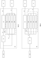
Figure 2 illustrates a panel of thefirst side 42 removed to show an exemplary electrical circuit of a charging unit which provides the battery charging functionality described herein. Acharger control unit 1 is operatively connected to four30kW charging modules 2. Thecharging modules 2 may be any of thecharging modules Figures 5 to 9 . A moulded case circuit breaker (MCCB) 3 is provided to provide overload protection to the electrical circuit. Acharger input contactor 4 is provided adjacent to an Earthleakage supervision relay 5. Two DC fuses 6 withrespective DC contactors 7 provide output power for theconnector 8. A battery (not shown) of a ground support equipment or vehicle can thus be charged via theconnector 8. - On a
second side 44 of thecabinet 40, there is provided a ground power unit (GPU) section for powering the aircraft as shown inFigures 3 and 4 . Thesecond side 44 of thecabinet 40 has auser interface 16 for the GPU section. Within thecabinet 40, there is aninput breaker 10, anoutput contactor 11 and anauxiliary power supply 12 for powering the aircraft. Theauxiliary power supply 12 is connected to a miniature circuit breaker, MCB, 14. A control unit 13 provided within thecabinet 40 controls the operation of the GPU section. Aconverter part 15 is also provided for providing the output to the aircraft. Theconverter part 15 may be any of thesolid state converters Figures 5 to 9 . - The GPU section includes a solid state converter to control the power supplied to the battery charging unit. As the solid state converter has a pre-set maximum power that it can draw from the airport power source and can monitor the power drawn by the aircraft (if any), the solid state converter can determine how much of the airport power source is surplus to present requirement and divert excess power to the battery charging unit. This can be achieved, for example, based on a control signal that is indicative of the maximum power available for the battery charging unit based on the difference between the known maximum power of the airport power source and the instantaneous power drawn by the aircraft. This would provide near-instantaneous power management within the ground support equipment to ensure power to the aircraft is always prioritised and that the electrical circuit is not overloaded. This advantageously does not require a current transducer or a separate load sharing controller as in the prior art. The present
ground support equipment 20 is therefore simpler in design as the controller of the solid state converter can be used to detect input current of the ground support equipment as a whole and generate a control signal based on the input current drawn by the solid state converter to determine any remaining power capacity of the airport power source. This control signal can then be transmitted or sent to the battery charging unit to control the amount of power drawn by the chargingmodules 2, for example from aDC bus 57 when present, as explained below. - In one example, the
ground support equipment 20 is pre-fused by an external 200A fuse in the feeder line of theground support equipment 20, which corresponds to approximately 138kW at 400V mains. In some cases, the GPU section is able to provide 90kW of power. In the illustrated example, four 30kW constantpower charging modules 2 are used to generate a total of 120kW. However, it would be apparent that other pre-determined maximum power levels, for example 180kW, could be provided by using a different arrangement of chargingmodules 2. - The battery charging unit section is illustrated with charging
modules 2 connected in parallel, which are powered from the airport power source, for example a 50/60Hz AC power source. In some cases, it is possible to use DC/DC modules powered from a 400Hz internal DC bus which provides an AC power output for the aircraft. - The control unit 13 is able to reduce the power consumption of the battery charging unit to avoid overloading the feeder circuit when there is a high power demand from the GPU section. As the aircraft rarely draws maximum power from the GPU section, there is typically capacity for charging battery-powered ground support equipment or vehicle while 400Hz power is supplied to the aircraft when on the ground. The DC charging is combined with a GPU section in the present
ground support equipment 20 to further utilise the existing electrical circuits that are present in GPUs. Specifically, a solid state converter which is able to monitor the power drawn by the aircraft and can control the amount of power that can be drawn by the chargingmodules 2. -
Figures 5 to 9 are schematic illustrations of exemplary electrical circuits which are suitable for implementing the ground support equipment described above.Figure 5 illustrates an electrical circuit within thecabinet 40 described above. Thecabinet 40 has an input for anairport power source 50 and anoutput 64 for anaircraft 65 and aseparate output 74 for DC charging a battery-poweredground support equipment 75, such as an electric vehicle in the manner described above. Theinput 50 is connected to arectifier 55 which provides aDC bus 57 for asolid state converter 60. Thesolid state converter 60 has an in-built inverter which provides asuitable output 64 for theaircraft 65, for example 200V AC at 400Hz. Theinput 50 is also connected to abattery charging unit 70 comprising a series of chargingmodules 70A-70D each having their own rectifier. The chargingmodules 70A-70D are connected in parallel and arranged to provide aDC output 74 for charging as explained above. The controller of thesolid state converter 60 is operatively connected to thebattery charging unit 70 and is able to send acontrol signal 59 to thebattery charging unit 70 in the manner described above. -
Figure 6 illustrates an alternative circuit where therectifier 55 is connected to both thesolid state converter 60 and thebattery charging unit 72, where the battery charging unit comprises a parallel arrangement of chargingmodules 72A-72D. In the electrical circuit ofFigure 6 , the arrangement of chargingmodules 72A-72D do not require an in-built rectifier, as the AC to DC conversion is provided byrectifier 55. In this example, theDC bus 57 is able to power the chargingmodules 72A-72D of thebattery charging unit 72, thesolid state converter 60 and any other components within the ground support equipment. The controller of thesolid state converter 60 is operatively connected to thebattery charging unit 72 and is able to send acontrol signal 59 to thebattery charging unit 72 in the manner described above. - In some cases, the solid state converter and/or the charging modules can have their own in-built rectifier. This advantageously does away with the need to have a
separate rectifier 55 to provide aDC bus 57 for powering the respective components. Similarly, it is possible to provide multiple smaller solid state converter modules rather than a single large component. This advantageously allows for the space within thecabinet 40 to be better utilised.Figure 7 illustrate an example, where there is no separate rectifier and the single solid state converter has been replaced by smaller solidstate converter modules 62A-62D each with an in-built rectifier. Theairport power source 50 is connected to the parallel arrangement of solidstate converter modules 62A-62D and also to the parallel arrangement of chargingmodules 70A-70D of thebattery charging unit 70.Charging modules 70A-70D provide power for DC charging as explained above, while the solidstate converter modules 62A-62D provide theoutput 64 for powering theaircraft 65 as explained above. It would be apparent the controller of any of the solidstate converter modules 62A-62D could be used to provide thecontrol signal 59 to thebattery charging unit 70 in the manner described above. - In some cases, the rectifier can be implemented as a series of
smaller rectifier modules 55A-55D as shown inFigure 8 . This advantageously allows for the space within thecabinet 40 to be better utilised. Therectifier modules 55A-55D are connected in parallel and provide aDC bus 57 for power components within thecabinet 40.Figure 8 illustrates a parallel arrangement of solidstate converter modules 60A-60D for providing anoutput 64 for powering theaircraft 65. In this case, the functionality of a rectifier is separated from the solidstate converter modules 60A-60D, so that solidstate converter modules 60A-60D without an in-built rectifier can be used with the present ground support equipment. As withFigure 6 , the chargingmodules 72A-72D of thebattery charging unit 72 also do not have an in-built rectifier. It would be apparent the controller of any of the solidstate converter modules 62A-62D could be used to provide thecontrol signal 59 to thebattery charging unit 72 in the manner described above. - A further electrical circuit is shown in
Figure 9 . Thecabinet 40 includes an input for receiving theairport power source 50, andoutput ports aircraft 65 and thebattery charger 75 respectively. In this circuit, aseparate rectifier 55 is connected to theairport power source 50 and provides aDC bus 57 for powering the chargingmodules 72A-72D of thebattery charging unit 72 independently of thesolid state converter 62. In this case, a singlesolid state converter 62 is connected directly to theairport power source 50 and includes an in-built rectifier and inverter to provide theoutput 64 for theaircraft 65. The controller of thesolid state converter 62 is operatively connected to thebattery charging unit 72 and is able to send acontrol signal 59 to thebattery charging unit 72 in the manner described above. - As will be appreciated by the exemplary circuits shown in
Figure 5 to 9 , it is possible to use multiple smaller modules in place of a single larger solid state converter, rectifier and/or charging module, although this is not essential. Similarly, it is possible for the solid state converter and/or the charging module(s) to include an in-built rectifier although this is not essential. In some cases, the inverter may be provided as a separate component to the solid state converter. - Throughout the description and claims of this specification, the words "comprise" and "contain" and variations of them mean "including but not limited to", and they are not intended to (and do not) exclude other moieties, additives, components, integers or steps. Throughout the description and claims of this specification, the singular encompasses the plural unless the context otherwise requires. In particular, where the indefinite article is used, the specification is to be understood as contemplating plurality as well as singularity, unless the context requires otherwise.
- Features, integers, characteristics, or groups described in conjunction with a particular aspect, embodiment or example of the invention are to be understood to be applicable to any other aspect, embodiment or example described herein unless incompatible therewith. All of the features disclosed in this specification (including any accompanying claims, abstract and drawings), and/or all of the steps of any method or process so disclosed, may be combined in any combination, except combinations where at least some of such features and/or steps are mutually exclusive. The invention is not restricted to the details of any foregoing embodiments. The invention extends to any novel one, or any novel combination, of the features disclosed in this specification (including any accompanying claims, abstract and drawings), or to any novel one, or any novel combination, of the steps of any method or process so disclosed.
Claims (15)
- A ground support equipment for powering an aircraft on the ground, the ground support equipment comprising:a solid state converter configured to power an aircraft on the ground from an airport power source having a pre-determined maximum power, anda battery charging unit configured to charge an external battery from the airport power source,wherein the solid state converter is configured to measure an instantaneous power drawn by the aircraft, andwherein the solid state converter is configured to generate a control signal for controlling the battery charging unit, the control signal being indicative of a maximum power available for the battery charging unit based on the difference between the pre-determined maximum power of the airport power source and the instantaneous power drawn by the aircraft.
- A ground support equipment according to claim 1, wherein the solid state converter is configured to receive a user input for setting the pre-determined maximum power.
- A ground support equipment according to claim 1 or 2, wherein the battery charging unit comprises a plurality of charging modules configured to receive power from the airport power source.
- A ground support equipment according to claim 3, wherein the plurality of charging modules are connected in parallel.
- A ground support equipment according to claim 2 or 3, wherein at least one of the plurality of charging modules are configured to provide a 30kW output.
- A ground support equipment according to any of claims 3 to 5, wherein at least one of the plurality of charging modules is configured to convert an AC input to a DC output.
- A ground support equipment according to any of claims 3 to 5 comprising a common rectifier configured to convert an AC input to a DC output to provide a DC bus for providing power to the battery charging unit.
- A ground support equipment according to claim 7, wherein the DC bus is configured to provide power to each of the plurality of charging modules.
- A ground support equipment according to any preceding claim, wherein the solid state converter is configured to provide a 400Hz output.
- A ground support equipment according to any preceding claim, wherein the solid state converter is configured to receive power from an AC power source.
- A ground support equipment according to any preceding claim, wherein the solid state converter is configured to provide up to 180kW output power.
- A ground support equipment according to any preceding claim, wherein the battery charging unit is configured to provide an output power of 120kW.
- A ground support equipment according to any preceding claim, wherein the battery charging unit is configured to provide a DC power output.
- A ground support equipment according to any preceding claim comprising a plurality of solid state converters configured to provide power to the aircraft.
- A ground support equipment according to claim 14, where in the plurality of solid state converters are connected in parallel.
Priority Applications (4)
| Application Number | Priority Date | Filing Date | Title |
|---|---|---|---|
| EP22163071.8A EP4245666B1 (en) | 2022-03-18 | 2022-03-18 | Ground support equipment |
| US18/122,969 US20230294841A1 (en) | 2022-03-18 | 2023-03-17 | Ground support equipment |
| CN202310261825.8A CN116780687A (en) | 2022-03-18 | 2023-03-17 | ground support equipment |
| JP2023043011A JP2023138487A (en) | 2022-03-18 | 2023-03-17 | ground support equipment |
Applications Claiming Priority (1)
| Application Number | Priority Date | Filing Date | Title |
|---|---|---|---|
| EP22163071.8A EP4245666B1 (en) | 2022-03-18 | 2022-03-18 | Ground support equipment |
Publications (2)
| Publication Number | Publication Date |
|---|---|
| EP4245666A1 true EP4245666A1 (en) | 2023-09-20 |
| EP4245666B1 EP4245666B1 (en) | 2025-06-25 |
Family
ID=80820033
Family Applications (1)
| Application Number | Title | Priority Date | Filing Date |
|---|---|---|---|
| EP22163071.8A Active EP4245666B1 (en) | 2022-03-18 | 2022-03-18 | Ground support equipment |
Country Status (4)
| Country | Link |
|---|---|
| US (1) | US20230294841A1 (en) |
| EP (1) | EP4245666B1 (en) |
| JP (1) | JP2023138487A (en) |
| CN (1) | CN116780687A (en) |
Citations (6)
| Publication number | Priority date | Publication date | Assignee | Title |
|---|---|---|---|---|
| US20130279212A1 (en) * | 2012-04-19 | 2013-10-24 | David Wayne Leadingham | Dual function solid state converter |
| EP3228546A1 (en) * | 2016-03-31 | 2017-10-11 | Bredenoord B.v. | Mobile ground power unit and method of use |
| US10589635B1 (en) * | 2019-03-01 | 2020-03-17 | The Boeing Company | Active voltage control for hybrid electric aircraft |
| US20200346551A1 (en) * | 2019-04-30 | 2020-11-05 | JBT AeroTech Corporation | Airport electric vehicle charging system |
| WO2021136815A1 (en) * | 2019-12-30 | 2021-07-08 | Diggia Solutions S.L. | Portable charging device for electric vehicles |
| WO2021178161A1 (en) * | 2020-03-05 | 2021-09-10 | Illinois Tool Works Inc. | A power-distribution system for an aircraft on the ground |
Family Cites Families (5)
| Publication number | Priority date | Publication date | Assignee | Title |
|---|---|---|---|---|
| US8614564B2 (en) * | 2010-11-18 | 2013-12-24 | GM Global Technology Operations LLS | Systems and methods for providing power to a load based upon a control strategy |
| CN102891613A (en) * | 2011-07-21 | 2013-01-23 | 台达电子企业管理(上海)有限公司 | Alternating current (AC) to direct current (DC) power converter and DC charging station |
| US10589874B2 (en) * | 2016-06-29 | 2020-03-17 | John Bean Technologies Corporation | Variable pneumatic output with constant electrical output driven by a single engine |
| CN107492941A (en) * | 2017-10-16 | 2017-12-19 | 四川航电微能源有限公司 | Charging pile device based on airport ground power supply |
| FR3101489B1 (en) * | 2019-09-30 | 2021-10-08 | Guinault Sa | Electric charger for aircraft maintenance equipment |
-
2022
- 2022-03-18 EP EP22163071.8A patent/EP4245666B1/en active Active
-
2023
- 2023-03-17 CN CN202310261825.8A patent/CN116780687A/en active Pending
- 2023-03-17 JP JP2023043011A patent/JP2023138487A/en active Pending
- 2023-03-17 US US18/122,969 patent/US20230294841A1/en active Pending
Patent Citations (6)
| Publication number | Priority date | Publication date | Assignee | Title |
|---|---|---|---|---|
| US20130279212A1 (en) * | 2012-04-19 | 2013-10-24 | David Wayne Leadingham | Dual function solid state converter |
| EP3228546A1 (en) * | 2016-03-31 | 2017-10-11 | Bredenoord B.v. | Mobile ground power unit and method of use |
| US10589635B1 (en) * | 2019-03-01 | 2020-03-17 | The Boeing Company | Active voltage control for hybrid electric aircraft |
| US20200346551A1 (en) * | 2019-04-30 | 2020-11-05 | JBT AeroTech Corporation | Airport electric vehicle charging system |
| WO2021136815A1 (en) * | 2019-12-30 | 2021-07-08 | Diggia Solutions S.L. | Portable charging device for electric vehicles |
| WO2021178161A1 (en) * | 2020-03-05 | 2021-09-10 | Illinois Tool Works Inc. | A power-distribution system for an aircraft on the ground |
Also Published As
| Publication number | Publication date |
|---|---|
| JP2023138487A (en) | 2023-10-02 |
| CN116780687A (en) | 2023-09-19 |
| US20230294841A1 (en) | 2023-09-21 |
| EP4245666B1 (en) | 2025-06-25 |
Similar Documents
| Publication | Publication Date | Title |
|---|---|---|
| CA2814564C (en) | Electrical power control system for a vehicle | |
| US11070073B2 (en) | Mobile power system with multiple DC-AC converters and related platforms and methods | |
| KR101437019B1 (en) | Power feed system for electric vehicle | |
| KR101984484B1 (en) | Dc power server for a dc microgrid | |
| EP4007115A1 (en) | Energy storage charging system | |
| US9484749B2 (en) | Electric power supply system for an aircraft, aircraft and airport power supply system | |
| US20140320083A1 (en) | Power converter | |
| KR101729483B1 (en) | A variable capacity charging system for vehicles | |
| EP4243242A1 (en) | Charge control device, charge system, charge control method, and program | |
| US20140015319A1 (en) | Charged power control system | |
| EP3467993A1 (en) | Battery driven ground power unit with improved construction, durability, durability and maintenance | |
| CN103023106B (en) | One-machine-and-multiple-charging electrombile charging system and method | |
| CN118748447A (en) | Charging equipment | |
| CN118539497B (en) | A distributed energy storage device with high-frequency isolation function | |
| CN113036894B (en) | Solar unmanned aerial vehicle electrical system architecture | |
| EP4245666A1 (en) | Ground support equipment | |
| KR20190131392A (en) | Grid connected terminal device for electric car charger and grid connection method | |
| RU2421863C1 (en) | Self-contained electric power supply system of movable objects | |
| CN118249496A (en) | A power distribution device and method for a DC power supply system of an unmanned aerial vehicle | |
| CN103457340B (en) | Direct current power source screen cabinet | |
| CN119058435B (en) | Energy storage devices, drive motors and new energy vehicles | |
| US20250233420A1 (en) | Power distribution control | |
| RU52274U1 (en) | INPUT DISTRIBUTION DEVICE | |
| CN120855480A (en) | Balance control generator | |
| GB2619009A (en) | Charging apparatus and method for providing a charging power |
Legal Events
| Date | Code | Title | Description |
|---|---|---|---|
| PUAI | Public reference made under article 153(3) epc to a published international application that has entered the european phase |
Free format text: ORIGINAL CODE: 0009012 |
|
| STAA | Information on the status of an ep patent application or granted ep patent |
Free format text: STATUS: THE APPLICATION HAS BEEN PUBLISHED |
|
| AK | Designated contracting states |
Kind code of ref document: A1 Designated state(s): AL AT BE BG CH CY CZ DE DK EE ES FI FR GB GR HR HU IE IS IT LI LT LU LV MC MK MT NL NO PL PT RO RS SE SI SK SM TR |
|
| STAA | Information on the status of an ep patent application or granted ep patent |
Free format text: STATUS: REQUEST FOR EXAMINATION WAS MADE |
|
| 17P | Request for examination filed |
Effective date: 20240308 |
|
| RBV | Designated contracting states (corrected) |
Designated state(s): AL AT BE BG CH CY CZ DE DK EE ES FI FR GB GR HR HU IE IS IT LI LT LU LV MC MK MT NL NO PL PT RO RS SE SI SK SM TR |
|
| REG | Reference to a national code |
Ref country code: DE Ref legal event code: R079 Free format text: PREVIOUS MAIN CLASS: B64F0001360000 Ipc: B64F0001350000 Ref document number: 602022016292 Country of ref document: DE |
|
| GRAP | Despatch of communication of intention to grant a patent |
Free format text: ORIGINAL CODE: EPIDOSNIGR1 |
|
| STAA | Information on the status of an ep patent application or granted ep patent |
Free format text: STATUS: GRANT OF PATENT IS INTENDED |
|
| RIC1 | Information provided on ipc code assigned before grant |
Ipc: B64F 1/35 20240101AFI20250120BHEP |
|
| INTG | Intention to grant announced |
Effective date: 20250219 |
|
| P01 | Opt-out of the competence of the unified patent court (upc) registered |
Free format text: CASE NUMBER: APP_15976/2025 Effective date: 20250401 |
|
| GRAS | Grant fee paid |
Free format text: ORIGINAL CODE: EPIDOSNIGR3 |
|
| GRAA | (expected) grant |
Free format text: ORIGINAL CODE: 0009210 |
|
| STAA | Information on the status of an ep patent application or granted ep patent |
Free format text: STATUS: THE PATENT HAS BEEN GRANTED |
|
| AK | Designated contracting states |
Kind code of ref document: B1 Designated state(s): AL AT BE BG CH CY CZ DE DK EE ES FI FR GB GR HR HU IE IS IT LI LT LU LV MC MK MT NL NO PL PT RO RS SE SI SK SM TR |
|
| REG | Reference to a national code |
Ref country code: GB Ref legal event code: FG4D |
|
| REG | Reference to a national code |
Ref country code: CH Ref legal event code: EP |
|
| REG | Reference to a national code |
Ref country code: CH Ref legal event code: EP |
|
| REG | Reference to a national code |
Ref country code: IE Ref legal event code: FG4D |
|
| REG | Reference to a national code |
Ref country code: DE Ref legal event code: R096 Ref document number: 602022016292 Country of ref document: DE |
|
| REG | Reference to a national code |
Ref country code: NL Ref legal event code: FP |
|
| PG25 | Lapsed in a contracting state [announced via postgrant information from national office to epo] |
Ref country code: FI Free format text: LAPSE BECAUSE OF FAILURE TO SUBMIT A TRANSLATION OF THE DESCRIPTION OR TO PAY THE FEE WITHIN THE PRESCRIBED TIME-LIMIT Effective date: 20250625 |
|
| REG | Reference to a national code |
Ref country code: LT Ref legal event code: MG9D |
|
| PG25 | Lapsed in a contracting state [announced via postgrant information from national office to epo] |
Ref country code: GR Free format text: LAPSE BECAUSE OF FAILURE TO SUBMIT A TRANSLATION OF THE DESCRIPTION OR TO PAY THE FEE WITHIN THE PRESCRIBED TIME-LIMIT Effective date: 20250926 Ref country code: NO Free format text: LAPSE BECAUSE OF FAILURE TO SUBMIT A TRANSLATION OF THE DESCRIPTION OR TO PAY THE FEE WITHIN THE PRESCRIBED TIME-LIMIT Effective date: 20250925 |
|
| PG25 | Lapsed in a contracting state [announced via postgrant information from national office to epo] |
Ref country code: BG Free format text: LAPSE BECAUSE OF FAILURE TO SUBMIT A TRANSLATION OF THE DESCRIPTION OR TO PAY THE FEE WITHIN THE PRESCRIBED TIME-LIMIT Effective date: 20250625 |
|
| PG25 | Lapsed in a contracting state [announced via postgrant information from national office to epo] |
Ref country code: HR Free format text: LAPSE BECAUSE OF FAILURE TO SUBMIT A TRANSLATION OF THE DESCRIPTION OR TO PAY THE FEE WITHIN THE PRESCRIBED TIME-LIMIT Effective date: 20250625 |
|
| PG25 | Lapsed in a contracting state [announced via postgrant information from national office to epo] |
Ref country code: RS Free format text: LAPSE BECAUSE OF FAILURE TO SUBMIT A TRANSLATION OF THE DESCRIPTION OR TO PAY THE FEE WITHIN THE PRESCRIBED TIME-LIMIT Effective date: 20250925 |
|
| PG25 | Lapsed in a contracting state [announced via postgrant information from national office to epo] |
Ref country code: LV Free format text: LAPSE BECAUSE OF FAILURE TO SUBMIT A TRANSLATION OF THE DESCRIPTION OR TO PAY THE FEE WITHIN THE PRESCRIBED TIME-LIMIT Effective date: 20250625 |
|
| PG25 | Lapsed in a contracting state [announced via postgrant information from national office to epo] |
Ref country code: PT Free format text: LAPSE BECAUSE OF FAILURE TO SUBMIT A TRANSLATION OF THE DESCRIPTION OR TO PAY THE FEE WITHIN THE PRESCRIBED TIME-LIMIT Effective date: 20251027 |
|
| REG | Reference to a national code |
Ref country code: AT Ref legal event code: MK05 Ref document number: 1806255 Country of ref document: AT Kind code of ref document: T Effective date: 20250625 |
|
| PG25 | Lapsed in a contracting state [announced via postgrant information from national office to epo] |
Ref country code: IS Free format text: LAPSE BECAUSE OF FAILURE TO SUBMIT A TRANSLATION OF THE DESCRIPTION OR TO PAY THE FEE WITHIN THE PRESCRIBED TIME-LIMIT Effective date: 20251025 |
|
| PG25 | Lapsed in a contracting state [announced via postgrant information from national office to epo] |
Ref country code: AT Free format text: LAPSE BECAUSE OF FAILURE TO SUBMIT A TRANSLATION OF THE DESCRIPTION OR TO PAY THE FEE WITHIN THE PRESCRIBED TIME-LIMIT Effective date: 20250625 Ref country code: SM Free format text: LAPSE BECAUSE OF FAILURE TO SUBMIT A TRANSLATION OF THE DESCRIPTION OR TO PAY THE FEE WITHIN THE PRESCRIBED TIME-LIMIT Effective date: 20250625 |
|
| PG25 | Lapsed in a contracting state [announced via postgrant information from national office to epo] |
Ref country code: CZ Free format text: LAPSE BECAUSE OF FAILURE TO SUBMIT A TRANSLATION OF THE DESCRIPTION OR TO PAY THE FEE WITHIN THE PRESCRIBED TIME-LIMIT Effective date: 20250625 |
|
| PG25 | Lapsed in a contracting state [announced via postgrant information from national office to epo] |
Ref country code: PL Free format text: LAPSE BECAUSE OF FAILURE TO SUBMIT A TRANSLATION OF THE DESCRIPTION OR TO PAY THE FEE WITHIN THE PRESCRIBED TIME-LIMIT Effective date: 20250625 |
|
| PG25 | Lapsed in a contracting state [announced via postgrant information from national office to epo] |
Ref country code: EE Free format text: LAPSE BECAUSE OF FAILURE TO SUBMIT A TRANSLATION OF THE DESCRIPTION OR TO PAY THE FEE WITHIN THE PRESCRIBED TIME-LIMIT Effective date: 20250625 |
|
| PG25 | Lapsed in a contracting state [announced via postgrant information from national office to epo] |
Ref country code: SK Free format text: LAPSE BECAUSE OF FAILURE TO SUBMIT A TRANSLATION OF THE DESCRIPTION OR TO PAY THE FEE WITHIN THE PRESCRIBED TIME-LIMIT Effective date: 20250625 |
|
| PG25 | Lapsed in a contracting state [announced via postgrant information from national office to epo] |
Ref country code: ES Free format text: LAPSE BECAUSE OF FAILURE TO SUBMIT A TRANSLATION OF THE DESCRIPTION OR TO PAY THE FEE WITHIN THE PRESCRIBED TIME-LIMIT Effective date: 20250625 |
|
| PGFP | Annual fee paid to national office [announced via postgrant information from national office to epo] |
Ref country code: GB Payment date: 20260327 Year of fee payment: 5 |
|
| PG25 | Lapsed in a contracting state [announced via postgrant information from national office to epo] |
Ref country code: DK Free format text: LAPSE BECAUSE OF FAILURE TO SUBMIT A TRANSLATION OF THE DESCRIPTION OR TO PAY THE FEE WITHIN THE PRESCRIBED TIME-LIMIT Effective date: 20250625 |
|
| PGFP | Annual fee paid to national office [announced via postgrant information from national office to epo] |
Ref country code: DE Payment date: 20260327 Year of fee payment: 5 |
|
| PG25 | Lapsed in a contracting state [announced via postgrant information from national office to epo] |
Ref country code: IT Free format text: LAPSE BECAUSE OF FAILURE TO SUBMIT A TRANSLATION OF THE DESCRIPTION OR TO PAY THE FEE WITHIN THE PRESCRIBED TIME-LIMIT Effective date: 20250625 |
|
| PGFP | Annual fee paid to national office [announced via postgrant information from national office to epo] |
Ref country code: NL Payment date: 20260326 Year of fee payment: 5 |
|
| PGFP | Annual fee paid to national office [announced via postgrant information from national office to epo] |
Ref country code: FR Payment date: 20260325 Year of fee payment: 5 |
|
| PGFP | Annual fee paid to national office [announced via postgrant information from national office to epo] |
Ref country code: TR Payment date: 20260309 Year of fee payment: 5 |
|
| PLBE | No opposition filed within time limit |
Free format text: ORIGINAL CODE: 0009261 |
|
| STAA | Information on the status of an ep patent application or granted ep patent |
Free format text: STATUS: NO OPPOSITION FILED WITHIN TIME LIMIT |