EP4245663A1 - Composite seat bottom diaphragm - Google Patents
Composite seat bottom diaphragm Download PDFInfo
- Publication number
- EP4245663A1 EP4245663A1 EP23162178.0A EP23162178A EP4245663A1 EP 4245663 A1 EP4245663 A1 EP 4245663A1 EP 23162178 A EP23162178 A EP 23162178A EP 4245663 A1 EP4245663 A1 EP 4245663A1
- Authority
- EP
- European Patent Office
- Prior art keywords
- seat
- diaphragm
- semi
- extension
- attachment
- Prior art date
- Legal status (The legal status is an assumption and is not a legal conclusion. Google has not performed a legal analysis and makes no representation as to the accuracy of the status listed.)
- Granted
Links
Images


Classifications
-
- B—PERFORMING OPERATIONS; TRANSPORTING
- B64—AIRCRAFT; AVIATION; COSMONAUTICS
- B64D—EQUIPMENT FOR FITTING IN OR TO AIRCRAFT; FLIGHT SUITS; PARACHUTES; ARRANGEMENT OR MOUNTING OF POWER PLANTS OR PROPULSION TRANSMISSIONS IN AIRCRAFT
- B64D11/00—Passenger or crew accommodation; Flight-deck installations not otherwise provided for
- B64D11/06—Arrangements of seats, or adaptations or details specially adapted for aircraft seats
- B64D11/0647—Seats characterised by special upholstery or cushioning features
Definitions
- Aircraft seats often employ a fabric-based diaphragm to support a seat cushion and passenger. Such diaphragms are difficult to install because they require stretching during installation, and they wear out rapidly. It would be advantageous to have an aircraft seat diaphragm that was easier to install and offered a longer service life than existing diaphragms.
- embodiments of the inventive concepts disclosed herein are directed to an aircraft seat diaphragm with a pre-stretched elastomeric fabric.
- the elastomeric fabric is bonded to a composite frame with features to insert the diaphragm into aircraft seat spreaders.
- the composite frame defines a rear extension that extends up along the rear of the seat for added support.
- the rear extension may correspond to a fabric portion that releasably attaches to the seat back of the aircraft seat.
- inventive concepts are not limited in their application to the details of construction and the arrangement of the components or steps or methodologies set forth in the following description or illustrated in the drawings.
- inventive concepts disclosed herein may be practiced without these specific details.
- well-known features may not be described in detail to avoid unnecessarily complicating the instant disclosure.
- inventive concepts disclosed herein are capable of other embodiments or of being practiced or carried out in various ways. Also, it is to be understood that the phraseology and terminology employed herein is for the purpose of description and should not be regarded as limiting.
- a letter following a reference numeral is intended to reference an embodiment of the feature or element that may be similar, but not necessarily identical, to a previously described element or feature bearing the same reference numeral (e.g., 1, 1a, 1b).
- reference numeral e.g. 1, 1a, 1b
- Such shorthand notations are used for purposes of convenience only, and should not be construed to limit the inventive concepts disclosed herein in any way unless expressly stated to the contrary.
- any reference to "one embodiment,” or “some embodiments” means that a particular element, feature, structure, or characteristic described in connection with the embodiment is included in at least one embodiment of the inventive concepts disclosed herein.
- the appearances of the phrase “in some embodiments” in various places in the specification are not necessarily all referring to the same embodiment, and embodiments of the inventive concepts disclosed may include one or more of the features expressly described or inherently present herein, or any combination of sub-combination of two or more such features, along with any other features which may not necessarily be expressly described or inherently present in the instant disclosure.
- embodiments of the inventive concepts disclosed herein are directed to an aircraft seat diaphragm with a pre-stretched elastomeric fabric.
- the elastomeric fabric is bonded, via a co-molding process, to a composite frame with features to insert the diaphragm into aircraft seat spreaders.
- the composite frame defines a rear extension that extends up along the rear of the seat for added support.
- the rear extension may correspond to a fabric portion that releasably attaches to the seat back of the aircraft seat.
- the seat diaphragm 100 includes a pre-stretched elastomeric fabric 102 bonded to a composite frame (obscured) that maintains tension in the pre-stretched elastomeric fabric 102.
- the composite frame defines attachment elements 104 that secure the composite frame (and thereby the pre-stretched elastomeric fabric 102) to seat spreaders.
- the elastomeric fabric 102 is comprised of Dymetrol; alternatively, or in addition, the elastomeric material 102 may be comprised of Crystal Flex lite.
- Other pre-stretchable / pre-tensionable materials may be used provided they are suitable for aircraft seat diaphragms and bonding to a composite frame.
- the seat diaphragm 100 includes a rear fabric extension 106.
- the rear fabric extension 106 may be an extension of the pre-stretched elastomeric fabric 102 or a separate fabric element, also bonded to the composite frame. Likewise, the rear fabric extension 106 may not be pre-stretched (tensioned).
- the rear fabric extension 106 includes a seat back attachment element 108 to releasably attach the rear fabric extension 106 to an aircraft seat back.
- the seat back attachment element 108 may comprise a zipper oriented to engage a corresponding zipper attached to the aircraft seat back.
- FIG. 2 a perspective, environmental view of a seat diaphragm 100 according to an exemplary embodiment is shown.
- the seat diaphragm 100 engages seat spreaders 202 to support a seat cushion 200 (and passenger).
- the composite frame in addition to maintaining tension in the pre-stretched elastomeric fabric, also supports some of the load of the seat cushion 200 and passenger at the periphery, reducing the load on the pre-stretched elastomeric fabric and thereby improving the service life of the seta diaphragm 100.
- the seat diaphragm 300 includes a pre-stretched elastomeric fabric 302 bonded to a composite frame 312.
- the composite frame defines attachment elements 304 that secure the composite frame to seat spreaders.
- the seat diaphragm 300 may include a non-tensioned rear fabric extension 306 bonded to the composite frame 312.
- the composite frame 312 is configured to be rigid or semi-rigid in at least one dimension such that the attachment elements 304 maintain their shape sufficiently for easy insertion into a corresponding spreader.
- the rear fabric extension 306 includes a seat back attachment element 308 (such as a zipper or components of a zipper) to releasably attach the rear fabric extension 306 to an aircraft seat back.
- the non-tensioned rear fabric extension 306 is bonded to a rear extension 310 of the composite frame 312.
- the rear extension 310 may comprise a portion of the composite frame 312 translated backward (with respect to a corresponding aircraft seat), and capable of conforming to the curvature of the rear fabric extension 306 when connected to a seat back.
- the shape of the composite frame 312 including the rear extension 310 produces a pressure map that is more desirable than a strictly rectangular composite frame 312. It may be appreciated that a continuous curved transition between the rear portion of the composite frame 312 and the rear extension 310 is desirable for comfort and for the service life of the seat diaphragm 300.
- the composite frame 312 may include seat cushion attachment elements 314.
- the seat cushion attachment elements 314 are disposed to engage corresponding attachment clips disposed on a bottom rear surface of a corresponding seat cushion.
- FIG. 4 a perspective, environmental view of a seat diaphragm 300 according to an exemplary embodiment is shown.
- the seat diaphragm 300 engages seat spreaders 402 to support a seat cushion 406.
- the seat cushion 406 is maintained in position via one or more attachment clips 414 disposed on the seat cushion 406.
- a rear fabric extension is releasably attached to a corresponding seat back 400 via a seat back attachment element 308.
- the seat back attachment element 308 provides a further support structure to seat diaphragm 300.
- the seat diaphragm includes a pre-stretched elastomeric fabric 502 bonded to a composite frame 512.
- the composite frame 512 defines spreader attachment elements 504 configured to engage corresponding spreaders 500 to define a seat cushion surface.
- the spreader attachment elements 504 may comprise a rail or keder configured to engage a channel defined by the corresponding spreader.
- the seat diaphragm may be installed in the spreaders 500 without the need to simultaneously stretch the seat fabric, making installation easier than existing seat diaphragms.
- the seat diaphragm 600 includes a pre-stretched elastomeric fabric 602 bonded to a composite frame 612 configured to be installed between two seat spreaders.
- the seat diaphragm 600 may include a non-tensioned rear fabric extension 606 bonded to a rear extension 610 of the composite frame 612.
- the composite frame 612 may include seat cushion attachment elements disposed to engage corresponding attachment clips 614 disposed on a bottom rear surface of a corresponding seat cushion 616.
- the seat diaphragm 700 including a pre-stretched elastomeric fabric 702 bonded to a composite frame 712 and a non-tensioned rear fabric extension 706 bonded to a rear extension 710 of the composite frame 712, includes seat cushion attachments elements 714.
- the seat cushion attachment elements 714 may comprise extruded or distended portions integrated into the composite frame 712.
- the seat cushion attachments elements 714 may operate in concert with a corresponding front frame structure, tube, or beam of the aircraft seat to limit or prevent both forward and backward movement of the seat cushion. As described more fully herein.
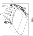
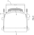
- FIGS. 8 and 9 a perspective and top, environmental view of a seat diaphragm according to an exemplary embodiment are shown.
- the seat comprises spreaders 802, 902 that support a seat back 804, 904 and a seat diaphragm (obscured) with a rear fabric portion 806, 906 releasably connecting the seat diaphragm to the seat back 804, 904.
- a seat cushion 800, 900 is disposed on the seat diaphragm, and in at least one embodiment, held in place via seat cushion attachment elements and clips disposed to engage on the seat diaphragm, and a front seat frame engaging section of the seat cushion 800, 900.
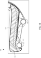
- FIG. 10 a side, partial view of a seat cushion 100 according to an exemplary embodiment is shown.
- An aircraft seat includes two spreaders 1002 configured to support a seat diaphragm.
- the diaphragm supports a load from the corresponding seat cushion 1000.
- the seat cushion 1000 may include attachment features, such as clips, to engage the diaphragm at a rear edge and prevent the seat cushion from sliding forward.
- a front portion of the seat cushion 1000 may define a forward frame attachment element 1010 configured to positively engage a forward frame element 1012 such as a tube or beam disposed between the spreaders 1002 at a forward portion of the seat.
- the forward frame element 1012 works to absorb some of the passenger load, thereby reducing the load on the diaphragm.
- the forward frame attachment element 1010 is configured to snap over the forward frame element 1012 when the attachment features are engaged to the diaphragm.
- the seat cushion 1000 may be removed for replacement or servicing the diaphragm by lifting the front of the seat cushion to disengage the forward frame attachment element 1010, then sliding the seat cushion 1000 backward to disengage the attachment features.
- the seat cushion 1000 comprises a lower portion 1006 of expanded polypropylene structural foam configured to provide more rigidity and load bearing than other portions of the seat cushion 1000.
- the expanded polypropylene structural foam may define forward frame attachment element 1010; that is, the forward frame attachment element 1010 may define a shape configured to snap over the forward frame element 1012.
- the seat cushion 1000 includes an upper portion 1004 of polyurethane foam configured for passenger comfort. Furthermore, the seat cushion 1000 may define a forward portion 1008 of polyurethane foam with a softer formulation than the upper portion 1004 for enhanced passenger comfort.
- Embodiments of the present disclosure provide added longevity and passenger comfort.
- the bulk of the occupant load is resolved via the composite frame.
- the cushion offers a hybrid approach by resting on the diaphragm and the structural forward-most beam of the seat frame.
Landscapes
- Engineering & Computer Science (AREA)
- Aviation & Aerospace Engineering (AREA)
- Seats For Vehicles (AREA)
Abstract
Description
- Aircraft seats often employ a fabric-based diaphragm to support a seat cushion and passenger. Such diaphragms are difficult to install because they require stretching during installation, and they wear out rapidly. It would be advantageous to have an aircraft seat diaphragm that was easier to install and offered a longer service life than existing diaphragms.
- In one aspect, embodiments of the inventive concepts disclosed herein are directed to an aircraft seat diaphragm with a pre-stretched elastomeric fabric. The elastomeric fabric is bonded to a composite frame with features to insert the diaphragm into aircraft seat spreaders.
- In a further aspect, the composite frame defines a rear extension that extends up along the rear of the seat for added support. The rear extension may correspond to a fabric portion that releasably attaches to the seat back of the aircraft seat.
- It is to be understood that both the foregoing general description and the following detailed description are exemplary and explanatory only and should not restrict the scope of the claims. The accompanying drawings, which are incorporated in and constitute a part of the specification, illustrate exemplary embodiments of the inventive concepts disclosed herein and together with the general description, serve to explain the principles.
- The numerous advantages of the embodiments of the inventive concepts disclosed herein may be better understood by those skilled in the art by reference to the accompanying figures in which:
- FIG. 1
- shows a perspective view of a seat diaphragm according to an exemplary embodiment;
- FIG. 2
- shows a perspective, environmental view of a seat diaphragm according to an exemplary embodiment;
- FIG. 3
- shows a perspective view of a seat diaphragm according to an exemplary embodiment;
- FIG. 4
- shows a perspective, environmental view of a seat diaphragm according to an exemplary embodiment;
- FIG. 5
- shows a perspective, detail view of a seat diaphragm according to an exemplary embodiment;
- FIG. 6
- shows a perspective, detail view of a seat diaphragm according to an exemplary embodiment;
- FIG. 7
- shows a perspective, detail view of a seat diaphragm according to an exemplary embodiment;
- FIG. 8
- shows a perspective, environmental view of a seat diaphragm according to an exemplary embodiment;
- FIG. 9
- shows a top, environmental view of a seat diaphragm according to an exemplary embodiment;
- FIG. 10
- shows a side, partial view of a seat cushion according to an exemplary embodiment;
- Before explaining at least one embodiment of the inventive concepts disclosed herein in detail, it is to be understood that the inventive concepts are not limited in their application to the details of construction and the arrangement of the components or steps or methodologies set forth in the following description or illustrated in the drawings. In the following detailed description of embodiments of the instant inventive concepts, numerous specific details are set forth in order to provide a more thorough understanding of the inventive concepts. However, it will be apparent to one of ordinary skill in the art having the benefit of the instant disclosure that the inventive concepts disclosed herein may be practiced without these specific details. In other instances, well-known features may not be described in detail to avoid unnecessarily complicating the instant disclosure. The inventive concepts disclosed herein are capable of other embodiments or of being practiced or carried out in various ways. Also, it is to be understood that the phraseology and terminology employed herein is for the purpose of description and should not be regarded as limiting.
- As used herein a letter following a reference numeral is intended to reference an embodiment of the feature or element that may be similar, but not necessarily identical, to a previously described element or feature bearing the same reference numeral (e.g., 1, 1a, 1b). Such shorthand notations are used for purposes of convenience only, and should not be construed to limit the inventive concepts disclosed herein in any way unless expressly stated to the contrary.
- Further, unless expressly stated to the contrary, "or" refers to an inclusive or and not to an exclusive or. For example, a condition A or B is satisfied by anyone of the following: A is true (or present) and B is false (or not present), A is false (or not present) and B is true (or present), and both A and B are true (or present).
- In addition, use of the "a" or "an" are employed to describe elements and components of embodiments of the instant inventive concepts. This is done merely for convenience and to give a general sense of the inventive concepts, and "a" and "an" are intended to include one or at least one and the singular also includes the plural unless it is obvious that it is meant otherwise.
- Also, while various components may be depicted as being connected directly, direct connection is not a requirement. Components may be in data communication with intervening components that are not illustrated or described.
- Finally, as used herein any reference to "one embodiment," or "some embodiments" means that a particular element, feature, structure, or characteristic described in connection with the embodiment is included in at least one embodiment of the inventive concepts disclosed herein. The appearances of the phrase "in some embodiments" in various places in the specification are not necessarily all referring to the same embodiment, and embodiments of the inventive concepts disclosed may include one or more of the features expressly described or inherently present herein, or any combination of sub-combination of two or more such features, along with any other features which may not necessarily be expressly described or inherently present in the instant disclosure.
- Broadly, embodiments of the inventive concepts disclosed herein are directed to an aircraft seat diaphragm with a pre-stretched elastomeric fabric. The elastomeric fabric is bonded, via a co-molding process, to a composite frame with features to insert the diaphragm into aircraft seat spreaders. The composite frame defines a rear extension that extends up along the rear of the seat for added support. The rear extension may correspond to a fabric portion that releasably attaches to the seat back of the aircraft seat.
- Referring to
FIG. 1 , a perspective view of aseat diaphragm 100 according to an exemplary embodiment is shown. Theseat diaphragm 100 includes a pre-stretchedelastomeric fabric 102 bonded to a composite frame (obscured) that maintains tension in the pre-stretchedelastomeric fabric 102. The composite frame definesattachment elements 104 that secure the composite frame (and thereby the pre-stretched elastomeric fabric 102) to seat spreaders. In at least one embodiment, theelastomeric fabric 102 is comprised of Dymetrol; alternatively, or in addition, theelastomeric material 102 may be comprised of Crystal Flex lite. Other pre-stretchable / pre-tensionable materials may be used provided they are suitable for aircraft seat diaphragms and bonding to a composite frame. - In at least one embodiment, the
seat diaphragm 100 includes arear fabric extension 106. Therear fabric extension 106 may be an extension of the pre-stretchedelastomeric fabric 102 or a separate fabric element, also bonded to the composite frame. Likewise, therear fabric extension 106 may not be pre-stretched (tensioned). In at least one embodiment, therear fabric extension 106 includes a seatback attachment element 108 to releasably attach therear fabric extension 106 to an aircraft seat back. In at least one embodiment, the seatback attachment element 108 may comprise a zipper oriented to engage a corresponding zipper attached to the aircraft seat back. - Referring to
FIG. 2 , a perspective, environmental view of aseat diaphragm 100 according to an exemplary embodiment is shown. Theseat diaphragm 100 engagesseat spreaders 202 to support a seat cushion 200 (and passenger). The composite frame, in addition to maintaining tension in the pre-stretched elastomeric fabric, also supports some of the load of theseat cushion 200 and passenger at the periphery, reducing the load on the pre-stretched elastomeric fabric and thereby improving the service life of theseta diaphragm 100. - Referring to
FIG. 3 , a perspective view of aseat diaphragm 300 according to an exemplary embodiment is shown. Theseat diaphragm 300 includes a pre-stretchedelastomeric fabric 302 bonded to acomposite frame 312. The composite frame definesattachment elements 304 that secure the composite frame to seat spreaders. Theseat diaphragm 300 may include a non-tensionedrear fabric extension 306 bonded to thecomposite frame 312. Thecomposite frame 312 is configured to be rigid or semi-rigid in at least one dimension such that theattachment elements 304 maintain their shape sufficiently for easy insertion into a corresponding spreader. - In at least one embodiment, the
rear fabric extension 306 includes a seat back attachment element 308 (such as a zipper or components of a zipper) to releasably attach therear fabric extension 306 to an aircraft seat back. In at least one embodiment, the non-tensionedrear fabric extension 306 is bonded to arear extension 310 of thecomposite frame 312. Therear extension 310 may comprise a portion of thecomposite frame 312 translated backward (with respect to a corresponding aircraft seat), and capable of conforming to the curvature of therear fabric extension 306 when connected to a seat back. The shape of thecomposite frame 312 including therear extension 310 produces a pressure map that is more desirable than a strictly rectangularcomposite frame 312. It may be appreciated that a continuous curved transition between the rear portion of thecomposite frame 312 and therear extension 310 is desirable for comfort and for the service life of theseat diaphragm 300. - In at least one embodiment, the
composite frame 312 may include seatcushion attachment elements 314. The seatcushion attachment elements 314 are disposed to engage corresponding attachment clips disposed on a bottom rear surface of a corresponding seat cushion. - Referring to
FIG. 4 , a perspective, environmental view of aseat diaphragm 300 according to an exemplary embodiment is shown. Theseat diaphragm 300 engagesseat spreaders 402 to support aseat cushion 406. Theseat cushion 406 is maintained in position via one or more attachment clips 414 disposed on theseat cushion 406. - In at least one embodiment, a rear fabric extension is releasably attached to a corresponding seat back 400 via a seat back
attachment element 308. The seat backattachment element 308 provides a further support structure toseat diaphragm 300. - Referring to
FIG. 5 , a perspective, detail view of a seat diaphragm according to an exemplary embodiment is shown. In at least one embodiment, the seat diaphragm includes a pre-stretchedelastomeric fabric 502 bonded to acomposite frame 512. Thecomposite frame 512 definesspreader attachment elements 504 configured to engage correspondingspreaders 500 to define a seat cushion surface. In at least one embodiment, thespreader attachment elements 504 may comprise a rail or keder configured to engage a channel defined by the corresponding spreader. Because theelastomeric fabric 502 is pre-stretched, and tension is maintained by thecomposite frame 512, the seat diaphragm may be installed in thespreaders 500 without the need to simultaneously stretch the seat fabric, making installation easier than existing seat diaphragms. - Referring to
FIG. 6 , a perspective, detail view of a seat diaphragm according to an exemplary embodiment is shown. The seat diaphragm 600 includes a pre-stretchedelastomeric fabric 602 bonded to acomposite frame 612 configured to be installed between two seat spreaders. The seat diaphragm 600 may include a non-tensionedrear fabric extension 606 bonded to arear extension 610 of thecomposite frame 612. - In at least one embodiment, the
composite frame 612 may include seat cushion attachment elements disposed to engage corresponding attachment clips 614 disposed on a bottom rear surface of acorresponding seat cushion 616. - Referring to
FIG. 7 , a perspective, detail view of a seat diaphragm according to an exemplary embodiment is shown. The seat diaphragm 700, including a pre-stretchedelastomeric fabric 702 bonded to a composite frame 712 and a non-tensionedrear fabric extension 706 bonded to arear extension 710 of the composite frame 712, includes seatcushion attachments elements 714. The seatcushion attachment elements 714 may comprise extruded or distended portions integrated into the composite frame 712. In at least one embodiment, the seatcushion attachments elements 714 may operate in concert with a corresponding front frame structure, tube, or beam of the aircraft seat to limit or prevent both forward and backward movement of the seat cushion. As described more fully herein. - Referring to
FIGS. 8 and9 , a perspective and top, environmental view of a seat diaphragm according to an exemplary embodiment are shown. The seat comprisesspreaders rear fabric portion 806, 906 releasably connecting the seat diaphragm to the seat back 804, 904. Aseat cushion 800, 900 is disposed on the seat diaphragm, and in at least one embodiment, held in place via seat cushion attachment elements and clips disposed to engage on the seat diaphragm, and a front seat frame engaging section of theseat cushion 800, 900. - Referring to
FIG. 10 , a side, partial view of aseat cushion 100 according to an exemplary embodiment is shown. An aircraft seat includes twospreaders 1002 configured to support a seat diaphragm. The diaphragm supports a load from thecorresponding seat cushion 1000. - In at least one embodiment, the
seat cushion 1000 may include attachment features, such as clips, to engage the diaphragm at a rear edge and prevent the seat cushion from sliding forward. Furthermore, a front portion of theseat cushion 1000 may define a forwardframe attachment element 1010 configured to positively engage aforward frame element 1012 such as a tube or beam disposed between thespreaders 1002 at a forward portion of the seat. Theforward frame element 1012 works to absorb some of the passenger load, thereby reducing the load on the diaphragm. The forwardframe attachment element 1010 is configured to snap over theforward frame element 1012 when the attachment features are engaged to the diaphragm. Theseat cushion 1000 may be removed for replacement or servicing the diaphragm by lifting the front of the seat cushion to disengage the forwardframe attachment element 1010, then sliding theseat cushion 1000 backward to disengage the attachment features. - In at least one embodiment, the
seat cushion 1000 comprises alower portion 1006 of expanded polypropylene structural foam configured to provide more rigidity and load bearing than other portions of theseat cushion 1000. Furthermore, the expanded polypropylene structural foam may define forwardframe attachment element 1010; that is, the forwardframe attachment element 1010 may define a shape configured to snap over theforward frame element 1012. - In at least one embodiment, the
seat cushion 1000 includes anupper portion 1004 of polyurethane foam configured for passenger comfort. Furthermore, theseat cushion 1000 may define aforward portion 1008 of polyurethane foam with a softer formulation than theupper portion 1004 for enhanced passenger comfort. - Embodiments of the present disclosure provide added longevity and passenger comfort. The bulk of the occupant load is resolved via the composite frame. The cushion offers a hybrid approach by resting on the diaphragm and the structural forward-most beam of the seat frame.
- It is believed that the inventive concepts disclosed herein and many of their attendant advantages will be understood by the foregoing description of embodiments of the inventive concepts disclosed, and it will be apparent that various changes may be made in the form, construction, and arrangement of the components thereof without departing from the broad scope of the inventive concepts disclosed herein or without sacrificing all of their material advantages; and individual features from various embodiments may be combined to arrive at other embodiments. The form herein before described being merely an explanatory embodiment thereof, it is the intention of the following claims to encompass and include such changes. Furthermore, any of the features disclosed in relation to any of the individual embodiments may be incorporated into any other embodiment.
Claims (15)
- A seat diaphragm comprising:a semi-rigid composite frame (512); anda pre-stretched elastomeric fabric (502) bonded to the elastomeric frame,wherein the semi-rigid composite frame defines a plurality of spreader attachment elements (504), each configured to engage a corresponding spreader (500) and support a seat cushion and passenger.
- The seat diaphragm of Claim 1, further comprising a rear fabric extension (306).
- The seat diaphragm of Claim 2, wherein the semi-rigid frame defines a rear extension (310) bonded to the rear fabric extension (306), and optionally
wherein the semi-rigid frame defines a constant width such that the rear extension (310) corresponds to a translated portion of a rear segment of the semi-rigid frame (312). - The seat diaphragm of Claim 2 or 3, further comprising a releasable seat back attachment element (308) disposed on a distal edge of the rear fabric extension (306), the releasable seat back attachment element configured to releasably attach the rear fabric extension to a seat back.
- The seat diaphragm of any preceding Claim, further comprising one or more seat cushion attachment points (314) disposed at a rear edge of the semi-rigid frame (312), the one or more seat cushion attachment points (314) configured to releasably engage attachment clips (414) disposed on a rear, bottom surface of the seat cushion (406), and/or
wherein the spreader attachment elements (504) comprise linear rails, each configured to engage a channel defined by the corresponding spreader (500). - An aircraft seat comprising:two spreaders (500); anda seat diaphragm comprising:a semi-rigid composite frame (512); anda pre-stretched elastomeric fabric (502) bonded to the elastomeric frame,wherein the semi-rigid composite frame defines a plurality of spreader attachment elements (504), each configured to engage a corresponding spreader (504).
- The aircraft seat of Claim 6, wherein the seat diaphragm further comprises a rear fabric extension (306).
- The aircraft seat of Claim 7, wherein the semi-rigid frame defines a rear extension (310) bonded to the rear fabric extension (306), optionally
wherein the semi-rigid frame defines a constant width such that the rear extension (310) corresponds to a translated portion of a rear segment of the semi-rigid frame (312). - The aircraft seat of Claim 7 or 8, further comprising a seat back (400), wherein the seat diaphragm further comprises a releasable seat back attachment element (308) disposed on a distal edge of the rear fabric extension (306), the releasable seat back attachment element (308) configured to releasably attach the rear fabric extension to the seat back.
- The aircraft seat of any of Claims 6 to 9, further comprising a seat cushion (406), wherein the seat diaphragm further comprises one or more seat cushion attachment points (314) disposed at a rear edge of the semi-rigid frame, the one or more seat cushion attachment points configured to releasably engage attachment clips disposed on a rear, bottom surface of the seat cushion; and/or
wherein the spreader attachment elements (504) comprise linear rails, each configured to engage a channel defined by the corresponding spreader (500). - An aircraft seat comprising:two spreaders (500), each defining a seat diaphragm channel; anda seat diaphragm comprising:a semi-rigid composite frame (512); anda pre-stretched elastomeric fabric (502) bonded to the elastomeric frame, wherein the semi-rigid composite frame defines a plurality of linear rails (504), each configured to engage a seat diaphragm channel.
- The aircraft seat of Claim 11, wherein the seat diaphragm further comprises a rear fabric extension (306).
- The aircraft seat of Claim 12, wherein the semi-rigid frame (312) defines a rear extension (310) bonded to the rear fabric extension (306), and optionally
wherein the semi-rigid frame defines a constant width such that the rear extension corresponds to a translated portion of a rear segment of the semi-rigid frame. - The aircraft seat of Claim 12 or 13, further comprising a seat back (400), wherein the seat diaphragm further comprises a releasable seat back attachment element (308) disposed on a distal edge of the rear fabric extension (306), the releasable seat back attachment element configured to releasably attach the rear fabric extension to the seat back.
- The aircraft seat of any of Claims 11 to 14, further comprising a seat cushion (406), wherein the seat diaphragm further comprises one or more seat cushion attachment points (314) disposed at a rear edge of the semi-rigid frame, the one or more seat cushion attachment points configured to releasably engage attachment clips disposed on a rear, bottom surface of the seat cushion.
Applications Claiming Priority (1)
| Application Number | Priority Date | Filing Date | Title |
|---|---|---|---|
| US17/697,262 US11827363B2 (en) | 2022-03-17 | 2022-03-17 | Composite seat bottom diaphragm |
Publications (2)
| Publication Number | Publication Date |
|---|---|
| EP4245663A1 true EP4245663A1 (en) | 2023-09-20 |
| EP4245663B1 EP4245663B1 (en) | 2026-04-29 |
Family
ID=85704054
Family Applications (1)
| Application Number | Title | Priority Date | Filing Date |
|---|---|---|---|
| EP23162178.0A Active EP4245663B1 (en) | 2022-03-17 | 2023-03-15 | Composite seat bottom diaphragm |
Country Status (2)
| Country | Link |
|---|---|
| US (1) | US11827363B2 (en) |
| EP (1) | EP4245663B1 (en) |
Cited By (1)
| Publication number | Priority date | Publication date | Assignee | Title |
|---|---|---|---|---|
| EP4512720A1 (en) * | 2023-08-22 | 2025-02-26 | B/E Aerospace, Inc. | Hybrid bottom seat cushion |
Citations (3)
| Publication number | Priority date | Publication date | Assignee | Title |
|---|---|---|---|---|
| US20150239566A1 (en) * | 2013-02-27 | 2015-08-27 | The Boeing Company | Variable Thermal Resistance Device for Vehicular Seats |
| US10669030B1 (en) * | 2019-04-23 | 2020-06-02 | B/E Aerospace, Inc. | Seat pan diaphragm |
| US11203434B2 (en) * | 2019-10-28 | 2021-12-21 | B/E Aersospace, Inc. | Diaphragm attachment method for aircraft seating |
Family Cites Families (18)
| Publication number | Priority date | Publication date | Assignee | Title |
|---|---|---|---|---|
| US5485976A (en) * | 1994-01-12 | 1996-01-23 | Weber Aircraft, Inc. | Plastic bottom diaphragm for aircraft seat |
| US6644738B2 (en) * | 2001-11-21 | 2003-11-11 | B E Aerospace, Inc. | Aircraft passenger seat frame construction |
| ITTO20020097A1 (en) * | 2002-02-01 | 2003-08-01 | Petra Italia S A S Di Marina B | VEHICLE SEAT. |
| AT502289B1 (en) | 2005-08-08 | 2010-11-15 | Greiner Purtec Gmbh | UPHOLSTERY FOR A PASSENGER SEAT |
| US7871039B2 (en) * | 2007-05-22 | 2011-01-18 | The Boeing Company | Modular passenger seat for an aircraft |
| EP2293980B1 (en) | 2008-07-08 | 2016-03-23 | BE Aerospace, Inc. | Articulating passenger seat |
| US8550564B1 (en) | 2010-04-01 | 2013-10-08 | The Boeing Company | Composite seat pan structure for a lightweight aircraft seat assembly |
| US8783771B2 (en) * | 2011-11-21 | 2014-07-22 | Be Aerospace, Inc. | Extendable seat pan assembly with comfort spring |
| US8782835B2 (en) | 2012-03-20 | 2014-07-22 | Be Aerospace, Inc. | Seat cushion with integrated seat frame attachment structure |
| US9580175B2 (en) | 2013-04-04 | 2017-02-28 | Franklin Products, Inc. | Aircraft seat back assembly |
| DE102015114677A1 (en) * | 2015-09-02 | 2017-03-02 | Recaro Aircraft Seating Gmbh & Co. Kg | Aircraft seat device |
| EP3416525B1 (en) | 2016-03-31 | 2023-03-01 | Franklin Products, Inc. | Seating suspension diaphragm having integrated slide-in attachment means |
| US10144515B2 (en) * | 2016-04-01 | 2018-12-04 | Encore Seats, Inc. | Aircraft seating assembly and components |
| US10766622B2 (en) * | 2017-10-23 | 2020-09-08 | Yaborã Indústria Aeronáutica S.A. | Lightweight vehicle passenger seat assemblies |
| US10836495B2 (en) * | 2018-10-24 | 2020-11-17 | Safran Seats Usa Llc | Passenger seat with suspended seat diaphragm |
| US11089880B1 (en) * | 2019-11-11 | 2021-08-17 | B/E Aerospace, Inc. | Upholstery cover retention assembly |
| WO2021236443A1 (en) | 2020-05-18 | 2021-11-25 | Stryker Corporation | Patient support apparatus and accessories therefor |
| AU2021300880B2 (en) | 2020-07-02 | 2022-12-08 | Retract Canopy Systems Pty Ltd | Automotive cargo/tray cover assembly |
-
2022
- 2022-03-17 US US17/697,262 patent/US11827363B2/en active Active
-
2023
- 2023-03-15 EP EP23162178.0A patent/EP4245663B1/en active Active
Patent Citations (3)
| Publication number | Priority date | Publication date | Assignee | Title |
|---|---|---|---|---|
| US20150239566A1 (en) * | 2013-02-27 | 2015-08-27 | The Boeing Company | Variable Thermal Resistance Device for Vehicular Seats |
| US10669030B1 (en) * | 2019-04-23 | 2020-06-02 | B/E Aerospace, Inc. | Seat pan diaphragm |
| US11203434B2 (en) * | 2019-10-28 | 2021-12-21 | B/E Aersospace, Inc. | Diaphragm attachment method for aircraft seating |
Cited By (1)
| Publication number | Priority date | Publication date | Assignee | Title |
|---|---|---|---|---|
| EP4512720A1 (en) * | 2023-08-22 | 2025-02-26 | B/E Aerospace, Inc. | Hybrid bottom seat cushion |
Also Published As
| Publication number | Publication date |
|---|---|
| EP4245663B1 (en) | 2026-04-29 |
| US11827363B2 (en) | 2023-11-28 |
| US20230294832A1 (en) | 2023-09-21 |
Similar Documents
| Publication | Publication Date | Title |
|---|---|---|
| US20180229634A1 (en) | Trim clip | |
| EP2230177B1 (en) | Lightweight aircraft passenger seat with composite structure | |
| US10300821B2 (en) | Vehicle seat having cushion pan and metal frame | |
| EP2828156B1 (en) | Seat cushion with integrated seat frame attachment structure | |
| KR101443671B1 (en) | Vehicle seat construction | |
| CN111824428B (en) | Seat disc diaphragm | |
| US7794021B2 (en) | Cushion spring retaining structure | |
| CN107472184B (en) | Side airbag energy management system | |
| US10166895B2 (en) | Seatback comfort carrier | |
| US20120256450A1 (en) | Vehicle seat | |
| CN115230548B (en) | Seating arrangement | |
| US11413997B2 (en) | Vehicle seat | |
| EP3816048B1 (en) | Diaphragm attachment method for aircraft seating | |
| US10166894B2 (en) | Seatback comfort carrier | |
| US11827363B2 (en) | Composite seat bottom diaphragm | |
| US10377279B2 (en) | Integrated decking arm support feature | |
| JPWO2018025796A1 (en) | Sheet | |
| JP2017081364A (en) | Seat device and front cover | |
| CA2498466C (en) | Method of tensioning fabric and furniture construction | |
| US20170015227A1 (en) | Vehicle seat | |
| CN106335418B (en) | Vehicle seat | |
| US11850981B2 (en) | Lightweight cushion suspension and seating surface | |
| US11465752B2 (en) | Seat assembly with hybrid spring-based cushion support | |
| CN107207094B (en) | Seat suspension installation method and passenger seat | |
| US20240383385A1 (en) | Vehicle seat flap for concealing frame |
Legal Events
| Date | Code | Title | Description |
|---|---|---|---|
| PUAI | Public reference made under article 153(3) epc to a published international application that has entered the european phase |
Free format text: ORIGINAL CODE: 0009012 |
|
| STAA | Information on the status of an ep patent application or granted ep patent |
Free format text: STATUS: THE APPLICATION HAS BEEN PUBLISHED |
|
| AK | Designated contracting states |
Kind code of ref document: A1 Designated state(s): AL AT BE BG CH CY CZ DE DK EE ES FI FR GB GR HR HU IE IS IT LI LT LU LV MC ME MK MT NL NO PL PT RO RS SE SI SK SM TR |
|
| STAA | Information on the status of an ep patent application or granted ep patent |
Free format text: STATUS: REQUEST FOR EXAMINATION WAS MADE |
|
| 17P | Request for examination filed |
Effective date: 20240315 |
|
| RBV | Designated contracting states (corrected) |
Designated state(s): AL AT BE BG CH CY CZ DE DK EE ES FI FR GB GR HR HU IE IS IT LI LT LU LV MC ME MK MT NL NO PL PT RO RS SE SI SK SM TR |
|
| STAA | Information on the status of an ep patent application or granted ep patent |
Free format text: STATUS: EXAMINATION IS IN PROGRESS |
|
| 17Q | First examination report despatched |
Effective date: 20250218 |
|
| GRAP | Despatch of communication of intention to grant a patent |
Free format text: ORIGINAL CODE: EPIDOSNIGR1 |
|
| STAA | Information on the status of an ep patent application or granted ep patent |
Free format text: STATUS: GRANT OF PATENT IS INTENDED |
|
| INTG | Intention to grant announced |
Effective date: 20251111 |
|
| GRAS | Grant fee paid |
Free format text: ORIGINAL CODE: EPIDOSNIGR3 |
|
| GRAA | (expected) grant |
Free format text: ORIGINAL CODE: 0009210 |
|
| STAA | Information on the status of an ep patent application or granted ep patent |
Free format text: STATUS: THE PATENT HAS BEEN GRANTED |
|
| AK | Designated contracting states |
Kind code of ref document: B1 Designated state(s): AL AT BE BG CH CY CZ DE DK EE ES FI FR GB GR HR HU IE IS IT LI LT LU LV MC ME MK MT NL NO PL PT RO RS SE SI SK SM TR |
|
| REG | Reference to a national code |
Ref country code: CH Ref legal event code: F10 Free format text: ST27 STATUS EVENT CODE: U-0-0-F10-F00 (AS PROVIDED BY THE NATIONAL OFFICE) Effective date: 20260429 Ref country code: GB Ref legal event code: FG4D |