EP4245644A1 - Clutch apparatus, vehicle steering system, and vehicle - Google Patents
Clutch apparatus, vehicle steering system, and vehicle Download PDFInfo
- Publication number
- EP4245644A1 EP4245644A1 EP21914538.0A EP21914538A EP4245644A1 EP 4245644 A1 EP4245644 A1 EP 4245644A1 EP 21914538 A EP21914538 A EP 21914538A EP 4245644 A1 EP4245644 A1 EP 4245644A1
- Authority
- EP
- European Patent Office
- Prior art keywords
- transmission portion
- connecting rod
- transmission
- sleeve
- swing connecting
- Prior art date
- Legal status (The legal status is an assumption and is not a legal conclusion. Google has not performed a legal analysis and makes no representation as to the accuracy of the status listed.)
- Pending
Links
- 230000005540 biological transmission Effects 0.000 claims abstract description 411
- 230000007246 mechanism Effects 0.000 claims abstract description 97
- 230000033001 locomotion Effects 0.000 description 20
- 238000010586 diagram Methods 0.000 description 11
- 238000005265 energy consumption Methods 0.000 description 2
- 238000004519 manufacturing process Methods 0.000 description 2
- 230000009286 beneficial effect Effects 0.000 description 1
- 238000005516 engineering process Methods 0.000 description 1
- 230000006872 improvement Effects 0.000 description 1
- 238000012986 modification Methods 0.000 description 1
- 230000004048 modification Effects 0.000 description 1
- 230000001360 synchronised effect Effects 0.000 description 1
- 238000003466 welding Methods 0.000 description 1
Images


Classifications
-
- B—PERFORMING OPERATIONS; TRANSPORTING
- B62—LAND VEHICLES FOR TRAVELLING OTHERWISE THAN ON RAILS
- B62D—MOTOR VEHICLES; TRAILERS
- B62D1/00—Steering controls, i.e. means for initiating a change of direction of the vehicle
- B62D1/02—Steering controls, i.e. means for initiating a change of direction of the vehicle vehicle-mounted
- B62D1/16—Steering columns
- B62D1/20—Connecting steering column to steering gear
-
- B—PERFORMING OPERATIONS; TRANSPORTING
- B62—LAND VEHICLES FOR TRAVELLING OTHERWISE THAN ON RAILS
- B62D—MOTOR VEHICLES; TRAILERS
- B62D3/00—Steering gears
- B62D3/02—Steering gears mechanical
-
- B—PERFORMING OPERATIONS; TRANSPORTING
- B62—LAND VEHICLES FOR TRAVELLING OTHERWISE THAN ON RAILS
- B62D—MOTOR VEHICLES; TRAILERS
- B62D1/00—Steering controls, i.e. means for initiating a change of direction of the vehicle
- B62D1/02—Steering controls, i.e. means for initiating a change of direction of the vehicle vehicle-mounted
- B62D1/16—Steering columns
-
- B—PERFORMING OPERATIONS; TRANSPORTING
- B62—LAND VEHICLES FOR TRAVELLING OTHERWISE THAN ON RAILS
- B62D—MOTOR VEHICLES; TRAILERS
- B62D5/00—Power-assisted or power-driven steering
- B62D5/001—Mechanical components or aspects of steer-by-wire systems, not otherwise provided for in this maingroup
-
- F—MECHANICAL ENGINEERING; LIGHTING; HEATING; WEAPONS; BLASTING
- F16—ENGINEERING ELEMENTS AND UNITS; GENERAL MEASURES FOR PRODUCING AND MAINTAINING EFFECTIVE FUNCTIONING OF MACHINES OR INSTALLATIONS; THERMAL INSULATION IN GENERAL
- F16D—COUPLINGS FOR TRANSMITTING ROTATION; CLUTCHES; BRAKES
- F16D11/00—Clutches in which the members have interengaging parts
- F16D11/02—Clutches in which the members have interengaging parts disengaged by a contact of a part mounted on the clutch with a stationarily-mounted member
- F16D11/04—Clutches in which the members have interengaging parts disengaged by a contact of a part mounted on the clutch with a stationarily-mounted member with clutching members movable only axially
-
- B—PERFORMING OPERATIONS; TRANSPORTING
- B60—VEHICLES IN GENERAL
- B60Y—INDEXING SCHEME RELATING TO ASPECTS CROSS-CUTTING VEHICLE TECHNOLOGY
- B60Y2400/00—Special features of vehicle units
- B60Y2400/42—Clutches or brakes
-
- B—PERFORMING OPERATIONS; TRANSPORTING
- B60—VEHICLES IN GENERAL
- B60Y—INDEXING SCHEME RELATING TO ASPECTS CROSS-CUTTING VEHICLE TECHNOLOGY
- B60Y2410/00—Constructional features of vehicle sub-units
- B60Y2410/102—Shaft arrangements; Shaft supports, e.g. bearings
-
- B—PERFORMING OPERATIONS; TRANSPORTING
- B62—LAND VEHICLES FOR TRAVELLING OTHERWISE THAN ON RAILS
- B62D—MOTOR VEHICLES; TRAILERS
- B62D5/00—Power-assisted or power-driven steering
- B62D5/001—Mechanical components or aspects of steer-by-wire systems, not otherwise provided for in this maingroup
- B62D5/003—Backup systems, e.g. for manual steering
-
- F—MECHANICAL ENGINEERING; LIGHTING; HEATING; WEAPONS; BLASTING
- F16—ENGINEERING ELEMENTS AND UNITS; GENERAL MEASURES FOR PRODUCING AND MAINTAINING EFFECTIVE FUNCTIONING OF MACHINES OR INSTALLATIONS; THERMAL INSULATION IN GENERAL
- F16D—COUPLINGS FOR TRANSMITTING ROTATION; CLUTCHES; BRAKES
- F16D23/00—Details of mechanically-actuated clutches not specific for one distinct type
- F16D23/12—Mechanical clutch-actuating mechanisms arranged outside the clutch as such
- F16D2023/123—Clutch actuation by cams, ramps or ball-screw mechanisms
-
- F—MECHANICAL ENGINEERING; LIGHTING; HEATING; WEAPONS; BLASTING
- F16—ENGINEERING ELEMENTS AND UNITS; GENERAL MEASURES FOR PRODUCING AND MAINTAINING EFFECTIVE FUNCTIONING OF MACHINES OR INSTALLATIONS; THERMAL INSULATION IN GENERAL
- F16D—COUPLINGS FOR TRANSMITTING ROTATION; CLUTCHES; BRAKES
- F16D28/00—Electrically-actuated clutches
Definitions
- the present disclosure relates to the field of vehicle technologies, and more specifically, to a clutch apparatus, a vehicle steering system, and a vehicle.
- Vehicles in the related art are usually equipped with a vehicle steering system for controlling a driving direction of the vehicle.
- a function of the vehicle steering system is single.
- the steering system always transmits steering torque, and cannot stop transmitting steering torque.
- the wheels and the steering wheel are always linked.
- emerging functions such as in-vehicle multimedia function and automatic driving function, the vehicle steering system can no longer match these emerging functions, resulting in poor applicability and user experience.
- an objective of the present disclosure is to provide a clutch apparatus, and the clutch apparatus can transmit and stop transmitting steering torque with low costs and flexible arrangement.
- the present disclosure further provides a vehicle steering system having the clutch apparatus.
- the present disclosure further provides a vehicle having the vehicle steering system.
- the clutch apparatus includes: a first transmission portion and a second transmission portion, where the second transmission portion is movable between an engaged position and a disengaged position, the second transmission portion is engaged with the first transmission portion and transmits torque at the engaged position, and the second transmission portion is disengaged from the first transmission portion and stop transmitting torque at the disengaged position; a sleeve, sleeved on the second transmission portion; and a driving mechanism, including a driving apparatus and a linkage mechanism, where the linkage mechanism is in drive connection with the driving apparatus and the sleeve separately, the driving apparatus drives the linkage mechanism to move, to drive, through the sleeve, the second transmission portion to move between the engaged position and the disengaged position.
- the driving mechanism includes a driving apparatus and a linkage mechanism, where the linkage mechanism is in drive connection with the driving apparatus and the sleeve separately, and the driving apparatus drives the linkage mechanism to swing, to drive, through the sleeve, the second transmission portion to move between the engaged position and the disengaged position.
- the second transmission portion can move through the driving apparatus, so that steering torque can be transmitted and transmitting steering torque can be stopped.
- the linkage mechanism By arranging the linkage mechanism, while a driving force is transmitted between the driving apparatus and the second transmission portion, the linkage mechanism can increase a force for driving the second transmission portion to move, and therefore, requirements for the driving force outputted by the driving apparatus can be reduced, and costs of the driving apparatus are reduced.
- the linkage mechanism can increase movement travel of the second transmission portion, and can transmit the driving force in a long distance between the driving apparatus and the second transmission portion, improving arrangement flexibility of the second transmission portion, the sleeve, and the driving mechanism.
- the clutch apparatus can transmit steering torque and stop transmitting steering torque with low costs and flexible arrangement.
- first hinge point and a second hinge point between the linkage mechanism and the sleeve, and a connection line between the first hinge point and the second hinge point passes through a center of a cross section of the sleeve.
- the cross section of the sleeve is annular, and the first hinge point and the second hinge point are arranged opposite to each other in a radial direction of the sleeve.
- the clutch apparatus further includes: a third transmission portion, where the second transmission portion is connected to the third transmission portion, the second transmission portion cooperates with the third transmission portion to transmit torque, and the second transmission portion is movable relative to the third transmission portion between the engaged position and the disengaged position.
- the third transmission portion is constructed to include a cavity, and the second transmission portion extends into the cavity; and one of an inner circumferential surface of the third transmission portion and an outer circumferential surface of the second transmission portion is provided with a slide groove and the other is provided with a slide rail, the slide groove and the slide rail both extend in an axial direction of the first transmission portion and the second transmission portion, and the slide rail into with the slide groove.
- the second transmission portion includes: a shaft portion; a head portion, connected to an end of the shaft portion facing toward the first transmission portion, where when the second transmission portion is at the engaged position, the head portion is engaged with the first transmission portion; and when the second transmission portion is at the disengaged position, the head portion is disengaged from the first transmission portion.
- one of the first transmission portion and the second transmission portion is constructed to include a flange and the other is constructed to include a groove, and a cross section of the flange and a cross section of the groove are constructed into non-circular shapes adapted to each other, where when the second transmission portion is at the engaged position, the flange extends into the groove; and when the second transmission portion is at the disengaged position, the flange is disengaged from the groove.
- the clutch apparatus further includes: a housing, where at least a part of the first transmission portion, at least a part of the second transmission portion, and the sleeve are arranged in the housing, and the driving mechanism is mounted on the housing.
- the first transmission portion is supported on the housing by a first bearing; the second transmission portion is supported on the sleeve by a second bearing; and the sleeve is supported on the housing by a third bearing.
- the clutch apparatus further includes: an elastic member, acting on the sleeve and providing an elastic force for constantly pushing the second transmission portion toward the engaged position.
- the clutch apparatus further includes: a spring seat, sleeved on the second transmission portion and mounted in the sleeve; and a spring sleeve, sleeved on the second transmission portion and mounted in the housing, where the elastic member is a spring sleeved on the second transmission portion, and one end of the elastic member abuts against the spring seat and an other end abuts against the interior of the spring sleeve.
- the linkage mechanism is hingedly connected to the sleeve and the spring seat by a hinge shaft, and the housing is provided with a strip-shaped hole for the hinge shaft to pass through.
- the driving mechanism includes: a transmission mechanism, where the driving apparatus is in drive connection with the linkage mechanism through the transmission mechanism, the driving apparatus is hingedly connected to the housing, and the linkage mechanism is separately hingedly connected to the transmission mechanism, the housing, and the sleeve.
- the linkage mechanism includes: a first swing connecting rod, where one end of the first swing connecting rod is hingedly connected to the transmission mechanism, and an other end of the first swing connecting rod is hingedly connected to the sleeve; a second swing connecting rod, where one end of the second swing connecting rod is hingedly connected to the transmission mechanism, and an other end of the second swing connecting rod is hingedly connected to the sleeve; and a longitudinal connecting rod, where one end of the longitudinal connecting rod is hingedly connected to the housing, and an other end of the longitudinal connecting rod is hingedly connected to the first swing connecting rod and the second swing connecting rod.
- the transmission mechanism includes: an output screw rod, where the output screw rod is in drive connection with the driving apparatus; and an output nut, where the output nut is sleeved on the output screw rod and threadedly fits onto the output screw rod, where the end of the first swing connecting rod and the end of the second swing connecting rod are hingedly connected to the output nut.
- the transmission mechanism further includes: a transmission screw rod, where the driving apparatus is a motor, and the transmission screw rod is in drive connection with a motor shaft of the motor; a first transmission gear, where the first transmission gear meshes with the transmission screw rod; and a second transmission gear, where the second transmission gear is connected to the first transmission gear and rotates with the first transmission gear, and the second transmission gear meshes with the output screw rod.
- the first swing connecting rod and the second swing connecting rod are separately hingedly connected to two radial sides of the output nut respectively, and a hinge axis of the first swing connecting rod coincides with a hinge axis of the second swing connecting rod and is perpendicular to a radial direction of the output nut.
- the longitudinal connecting rod is hingedly connected to between two ends of the first swing connecting rod and between two ends of the second swing connecting rod, and a position of a hinge joint between the longitudinal connecting rod and the first swing connecting rod in a length direction of the first swing connecting rod is the same as the position of a hinge joint between the longitudinal connecting rod and the second swing connecting rod in a length direction of the second swing connecting rod.
- a vehicle steering system including: the clutch apparatus according to any foregoing embodiment of the present disclosure; a steering wheel, where the steering wheel is in drive connection with one of the first transmission portion and the second transmission portion; and a steering device, where the steering device is in drive connection with the other of the first transmission portion and the second transmission portion.
- the vehicle steering system according to the embodiments of the present disclosure by using the clutch apparatus according to any foregoing embodiment of the present disclosure, can transmit steering torque and stop transmitting steering torque with low costs and flexible arrangement.
- the vehicle steering system further includes a rotation angle limiting device, where the rotation angle limiting device is connected to one of the first transmission portion and the second transmission portion, and when the second transmission portion is at the disengaged position, the rotation angle limiting device limits a maximum rotation angle of the steering wheel by limiting a maximum rotation angle of one of the first transmission portion and the second transmission portion.
- the vehicle steering system further includes a rotation angle limiting device, where the rotation angle limiting device is connected to one of the first transmission portion and the second transmission portion, and when the second transmission portion is at the disengaged position, the rotation angle limiting device limits a maximum rotation angle of the steering wheel by limiting a maximum rotation angle of one of the first transmission portion and the second transmission portion.
- a vehicle including the vehicle steering system according to any foregoing embodiment of the present disclosure.
- the vehicle according to the embodiments of the present disclosure by using the vehicle steering system according to any foregoing embodiment of the present disclosure, can transmit steering torque and stop transmitting steering torque with low costs and flexible arrangement.
- orientations or position relationships indicated by terms such as “center”, “longitudinal”, “transverse”, “length”, “width”, “thickness”, “up”, “down”, “front”, “back”, “left”, “right”, “vertical”, “horizontal”, “top”, “bottom”, “inner”, “outer”, “clockwise”, “counterclockwise”, “axial”, “radial”, and “circumferential” are orientations or position relationship shown based on the accompanying drawings, and are merely used for describing the present disclosure and simplifying the descriptions, rather than indicating or implying that the apparatus or element should have a particular orientation or be constructed and operated in a particular orientation, and therefore, should not be construed as a limitation on the present disclosure.
- a clutch apparatus 1 according to the embodiments of the present disclosure is described below with reference to the accompanying drawings.
- the clutch apparatus 1 includes a first transmission portion 100, a second transmission portion 200, a sleeve 300, and a driving mechanism 400.
- the first transmission portion 100 and the second transmission portion 200 may be constructed into axial structures.
- the second transmission portion 200 is movable between an engaged position and a disengaged position, the second transmission portion 200 is engaged with the first transmission portion 100 and transmits torque at the engaged position, and the second transmission portion 200 is disengaged from the first transmission portion 100 and stops transmitting torque at the disengaged position.
- the sleeve 300 is sleeved on the second transmission portion 200.
- the driving mechanism 400 includes a driving apparatus 430 and a linkage mechanism 450.
- the linkage mechanism 450 is in drive connection with the driving apparatus 430 and the sleeve 300 separately, and the driving apparatus 430 drives the linkage mechanism 450 to swing, to drive, through the sleeve 300, the second transmission portion 200 to move between the engaged position and the disengaged position.
- the sleeve 300 and the second transmission portion 200 can synchronously move in an axial direction of the second transmission portion 200 and can rotate relative to each other in a circumferential direction of the second transmission portion 200. That is, the sleeve 300 and the second transmission portion 200 can synchronously move in an axial direction of the second transmission portion 200 and can rotate relative to each other in a circumferential direction of the second transmission portion 200.
- the clutch apparatus 1 makes the second transmission portion 200 movable between the engaged position and the disengaged position, the second transmission portion 200 is engaged with the first transmission portion 100 and transmits the torque at the engaged position, and the second transmission portion 200 is disengaged from the first transmission portion 100 and stops transmitting torque at the disengaged position. That is, when the first transmission portion 100 and the second transmission portion 200 are at the engaged position, the first transmission portion 100 and the second transmission portion 200 can synchronously rotate, as shown in FIG. 3 and FIG.
- first transmission portion 100 and the second transmission portion 200 can separately rotate, in other words, when the first transmission portion 100 rotates, the second transmission portion 200 may rotate or may not rotate. Similarly, when the second transmission portion 200 rotates, the first transmission portion 100 may rotate or may not rotate, as shown in FIG. 4 and FIG. 8 .
- the clutch apparatus 1 is applied to a vehicle steering system, and when the second transmission portion 200 is at the engaged position, the vehicle steering system can normally transmit moment of a steering wheel operated by a driver to a steering device.
- the steering wheel and the steering device are disconnected.
- the steering wheel is rotated, and the steering device is not driven to move with the steering wheel, but the steering wheel can still drive components, such as a combined switch, a clock spring, and an angle sensor, to normally operate.
- the steering wheel in this state may be used as a simulator of vehicle driving and may output a rotation angle signal of the steering wheel to an in-vehicle device or an external device.
- the steering wheel may be used for control in-vehicle multimedia and playing a racing game.
- movement of the steering device in this case does not drive the steering wheel to move.
- the steering device moves to control the entire vehicle to steer, and the steering wheel may not rotate with the steering device, to ensure safety of the driver and ride comfort.
- the sleeve 300 is sleeved on the second transmission portion 200
- the driving mechanism 400 includes the driving apparatus 430 and the linkage mechanism 450
- the linkage mechanism 450 is in drive connection with the driving apparatus 430 and the sleeve 300 separately
- the driving apparatus 430 drives the linkage mechanism 450 to move, for example, the driving apparatus 430 drives the linkage mechanism 450 to swing, to drive, through the sleeve 300, the second transmission portion 200 to move between the engaged position and the disengaged position.
- the second transmission portion 200 can move through the driving apparatus 430, so that steering torque can be transmitted and transmitting steering torque can be stopped.
- the linkage mechanism 450 can increase a force for driving the second transmission portion 200 to move, and therefore, requirements for the driving force outputted by the driving apparatus 430 can be reduced, and costs of the driving apparatus 430 are reduced.
- the linkage mechanism 450 can increase movement travel of the second transmission portion 200 and can transmit the driving force in a long distance between the driving apparatus 430 and the second transmission portion 200, and with diversity of force transmission of the linkage mechanism 450, while the sleeve 300 and the second transmission portion 200 are driven to move according to a predetermined path, requirements for position of the driving apparatus 430 are reduced, and arrangement flexibility of the driving apparatus 430 is improved.
- the sleeve 300 and the second transmission portion 200 can synchronously move in the axial direction of the second transmission portion 200, and the driving apparatus 430 and the second transmission portion 200 can rotate in the circumferential direction of the second transmission portion 200 in a same manner, so that the second transmission portion 200 can be driven, through the sleeve 300, to move in the axial direction, and the second transmission portion 200 can rotate without being affected by the sleeve 300.
- the clutch apparatus 1 can transmit steering torque and stop transmitting steering torque with low costs and flexible arrangement.
- FIG. 3 and FIG. 4 there are a first hinge point 310 and a second hinge point 410 between the linkage mechanism 450 and the sleeve 300, and a connection line between the first hinge point 310 and the second hinge point 410 passes through a center of a cross section of the sleeve 300.
- a force arm between the first hinge point 310 and the sleeve 300 and a force arm between the second hinge point 410 and the sleeve 300 are located at a same straight line.
- a moment of the entire clutch apparatus 1 may be symmetrical relative to a central axis of the clutch apparatus 1, which helps to remove a turning moment of the sleeve 300, ensures that the sleeve 300 moves in an extending direction of the sleeve 300, and increases movement smoothness of the second transmission portion 200, preventing the second transmission portion 200 from being stuck during movement.
- cross section of the sleeve 300 is a cross section perpendicular to an axial direction of the sleeve 300.
- a plane on which a cross section of the sleeve 300 is located passes through the first hinge point 310 and the second hinge point 410 at the same time
- the connection line between the first hinge point 310 and the second hinge point 410 passes through a center of the cross section
- a distance from the first hinge point 310 to the center of the cross section and a distance from the second hinge point 410 to the center of the cross section may be the same.
- the cross section of the sleeve 300 is annular, such as circular.
- the first hinge point 310 and the second hinge point 410 are arranged opposite to each other in a radial direction of the sleeve 300.
- Such shape rules of the sleeve 300 is for ease of production and processing, and disassembly and replacement.
- the entire sleeve 300 is uniformly forced, which avoids stress concentration, and further ensures movement smoothness of the second transmission portion 200.
- a shape of the cross section of the sleeve 300 is not limited to this, for example, the shape may alternatively be square.
- the clutch apparatus 1 further includes a third transmission portion 500.
- the third transmission portion 500 may alternatively be constructed into an axial structure, the second transmission portion 200 is connected to the third transmission portion 500, and the second transmission portion 200 cooperates with the third transmission portion 500 to transmit torque. That is, the second transmission portion 200 and the third transmission portion 500 can synchronously rotate to transmit the torque, and the second transmission portion 200 is movable relative to the third transmission portion 500 between the engaged position and the disengaged position (that is, movable in an axial direction).
- the third transmission portion 500 may be fixed to the steering wheel.
- the second transmission portion 200 and the third transmission portion 500 can synchronously rotate, that is, torque can be transmitted between the second transmission portion 200 and the third transmission portion 500, and the second transmission portion 200 and the third transmission portion 500 can independently move in the axial direction of the second transmission portion 200 (an axial direction of the third transmission portion 500), that is, when the second transmission portion 200 moves in the axial direction of the second transmission portion 200, the third transmission portion 500 does not move.
- the steering wheel can continue to synchronously rotate with the third transmission portion 500, ensuring that a position of the steering wheel is stable in the axial direction of the third transmission portion 500, so that the steering wheel can be used to input steering torque, and regardless of a moving manner of the second transmission portion 200 in the axial direction, the third transmission portion 500 can remove the movement, and then the steering wheel does not move in the axial direction.
- the third transmission portion 500 is constructed to include a cavity 510, the second transmission portion 200 extends into the cavity 510, one of an inner circumferential surface of the third transmission portion 500 and an outer circumferential surface of the second transmission portion 200 is provided with a slide groove and the other is provided with a slide rail, the slide groove and the slide rail both extend in the axial direction of the first transmission portion 100 and the second transmission portion 200, and the slide rail fits into the slide groove.
- the slide groove and the slide rail may be splines fitting each other.
- the axial direction of the first transmission portion 100, the axial direction of the second transmission portion 200, and the third transmission portion 500 may be parallel to each other. In this way, torque can be transmitted between the second transmission portion 200 and the third transmission portion 500, and the second transmission portion 200 and the third transmission portion 500 can relatively move in the axial direction with easy processing and low difficulty.
- the second transmission portion 200 includes a shaft portion 220 and a head portion 230.
- the head portion 230 is connected to an end of the shaft portion 220 facing toward the first transmission portion 100.
- the head portion 230 and the shaft portion 220 may be fixed by welding.
- a cross-sectional area of the head portion 230 may be greater than a cross-sectional area of the shaft portion 220.
- the torque is more stably transmitted between the second transmission portion 200 and the first transmission portion 100.
- the shaft portion 220 production cost of the second transmission portion 200 can be reduced, assembling space required for the second transmission portion 200 is reduced, and it is beneficial to miniaturization of the clutch apparatus 1.
- one of the first transmission portion 100 and the second transmission portion 200 is constructed to include a flange 110, and the other is constructed to include a groove 240.
- a cross section of the flange 110 and a cross section of the groove 240 are constructed into non-circular adapted to each other.
- the flange 110 is formed on an end surface of the head portion 230 facing toward the first transmission portion 100
- the groove 240 is formed on an end surface of the first transmission portion 100 facing toward the head portion 230
- the cross section of the flange 110 and the cross section of the groove 240 may be constructed into a cross shape, a rectangle, a wedge shape, a circular arc, an involute curve, or other curves.
- the flange 110 When the second transmission portion 200 is at the engaged position, the flange 110 extends into the groove 240; and when the second transmission portion 200 is at the disengaged position, the flange 110 is disengaged from the groove 240. In this way, when the first transmission portion 100 and the second transmission portion 200 are in an engaged state, the first transmission portion 100 is stably connected to the second transmission portion 200 to stably transmit torque.
- the clutch apparatus 1 further includes a housing 600. At least a part of the first transmission portion 100, at least a part of the second transmission portion 200, and the sleeve 300 are arranged in the housing 600. For example, a part of the first transmission portion 100, the second transmission portion 200, the sleeve 300, and a part of the third transmission portion 500 may be arranged in the housing 600.
- the driving mechanism 400 is mounted outside the housing 600.
- assembling position for the driving mechanism 400 is provided, on the other hand, a direct contact area between the first transmission portion 100 and the second transmission portion 200 and the outside can be reduced, and damage possibility of the first transmission portion 100 and the second transmission portion 200 is reduced.
- the first transmission portion 100 is supported on the housing 600 by a first bearing 610
- the second transmission portion 200 is supported on the sleeve 300 by a second bearing 330
- the sleeve 300 is supported on the housing 600 by a third bearing 320
- an end of the third transmission portion 500 away from the second transmission portion 200 may be supported in the housing 600 by a fourth bearing 520.
- the third bearing 320 may be a slide bearing, reducing sliding friction between the sleeve 300 and the housing 600.
- connection between the first transmission portion 100 and the housing 600 is stable while facilitating relative rotation
- connection between the sleeve 300 and the second transmission portion 200 is stable while facilitating relative rotation
- connection between the sleeve 300 and the housing 600 is stable while facilitating relative rotation
- connection between the third transmission portion 500 and the housing 600 is stable while facilitating relative rotation.
- an inner circumferential surface of the sleeve 300 and the outer circumferential surface of the second transmission portion 200 may be constructed to include a structure such as stairs, and therefore, relative positions of the sleeve 300, the second transmission portion 200, and the second bearing 330 in an axial direction of the clutch apparatus 1 are limited, ensuring that the sleeve 300 and the second transmission portion 200 can simultaneously move in the axial direction of the clutch apparatus 1.
- the clutch apparatus 1 further includes an elastic member 700.
- the elastic member 700 acts on the sleeve 300, and the elastic member 700 provides an elastic force for constantly pushing the second transmission portion 200 toward the engaged position.
- a thrust force for pushing the second transmission portion 200 toward the engaged position is increased, thereby increasing movement smoothness of the second transmission portion 200 toward the engaged position; on the other hand, when the second transmission portion 200 is located at the engaged position, contact between the first transmission portion 100 and the second transmission portion 200 is closer, connection is stable without energy consumption, and a fit clearance is further reduced.
- the clutch apparatus 1 further includes a spring seat 340 and a spring sleeve 620.
- the spring seat 340 is sleeved on the second transmission portion 200 and mounted in the sleeve 300
- the spring sleeve 620 is sleeved on the second transmission portion 200 and mounted in the housing 600.
- the elastic member 700 is a spring sleeved on the second transmission portion 200, and one end of the elastic member 700 abuts against the spring seat 340 and an other end abuts against the interior of the spring sleeve 620.
- a central axis of the spring seat 340, a central axis of the spring sleeve 620, a central axis of the elastic member 700, and a central axis of the second transmission portion 200 may coincide.
- an elastic force for constantly pushing the second transmission portion 200 toward the engaged position is easy to be provided by the elastic member 700; on the other hand, a moment of the entire second transmission portion 200 may keep symmetrical relative to the central axis of the second transmission portion, so as to ensure that a movement direction and an extending direction of the second transmission portion 200 is the same, thereby ensuring movement smoothness of the second transmission portion 200.
- a moment of the entire second transmission portion 200 may keep symmetrical relative to the central axis of the second transmission portion, so as to ensure that a movement direction and an extending direction of the second transmission portion 200 is the same, thereby ensuring movement smoothness of the second transmission portion 200.
- the spring seat 340 and the spring sleeve 620 it is ensured that the elastic force of the elastic member 700 can be transferred to the sleeve 300 and the housing 600, and a position of the elastic member 700 is stable.
- the linkage mechanism 450 is hingedly connected to the sleeve 300 and the spring seat 340 by a hinge shaft 460, and the housing 600 is provided with a strip-shaped hole 455 for the hinge shaft 460 to pass through, so as to facilitate mounting of the hinge shaft 460.
- connection of the linkage mechanism 450 with the sleeve 300 and the spring seat 340 is stable, and it is easy for the linkage mechanism 450 to swing relative to the sleeve 300 and the spring seat 340.
- the hinge shaft 460 can fix relative positions of the spring seat 340 and the sleeve 300, in this way, the hinge shaft 460 may be used to fix axial positions of the spring seat 340 and the sleeve 300 at the same time, so that the elastic force of the elastic member 700 is more reliable and accurately acts on the sleeve 300.
- arrangement of the strip-shaped hole 455 is convenient for the hinge shaft 460 to pass through the housing 600 and be hingedly connected to the sleeve 300, and the hinge shaft 460 can move in a length direction of the strip-shaped hole 455, so that when the second transmission portion 200 is driven to move, the hinge shaft 460 can move.
- the driving mechanism 400 further includes a transmission mechanism 440.
- the driving apparatus 430 is hingedly connected to the housing 600, the driving apparatus 430 is in drive connection with the linkage mechanism 450 through the transmission mechanism 440, and the linkage mechanism 450 is separately hingedly connected to the transmission mechanism 440, the housing 600, and the sleeve 300.
- the driving mechanism 400 adopts the transmission mechanism 440 to transfer a driving force of the driving apparatus 430 to the linkage mechanism 450. Transfer of the driving force is stable, and after the driving force acts on the transmission mechanism 440, a direction of a force outputted by the transmission mechanism 440 may be different from the driving force of the driving apparatus 430. Therefore, the direction of a force outputted by the transmission mechanism 440 can better meet requirements for movement of the linkage mechanism 450, increasing arrangement flexibility of the driving mechanism 400.
- the linkage mechanism 450 includes a first swing connecting rod 451, a second swing connecting rod 452, and a longitudinal connecting rod 453.
- One end of the first swing connecting rod 451 is hingedly connected to the transmission mechanism 440, an other end of the first swing connecting rod 451 is hingedly connected to the sleeve 300.
- One end of the second swing connecting rod 452 is hingedly connected to the transmission mechanism 440, an other end of the second swing connecting rod 452 is hingedly connected to the sleeve 300.
- One end of the longitudinal connecting rod 453 is hingedly connected to the housing 600, and an other end of the longitudinal connecting rod 453 is hingedly connected to the first swing connecting rod 451 and the second swing connecting rod 452.
- first swing connecting rod 451 and the second swing connecting rod 452 may be located on two opposite sides of the sleeve 300.
- a distance from a position of each swing connecting rod connected to the longitudinal connecting rod 453 to a position of the swing connecting rod hingedly connected to the sleeve 300 may be less than a distance from the position of each swing connecting rod connected to the longitudinal connecting rod 453 to a position of the swing connecting rod hingedly connected to the transmission mechanism 440.
- Two swing connecting rods are arranged to act on the sleeve 300, enabling the entire sleeve 300 to be forced more uniformly, so as to improve movement stability of the sleeve 300.
- arrangement of the longitudinal connecting rod 453 facilitates synchronous movement of the first swing connecting rod 451 and the second swing connecting rod 452, and two ends of the first swing connecting rod 451 and two ends of the second swing connecting rod 452 can swing with the longitudinal connecting rod 453 as a pivot point.
- Each swing connecting rod can form a structure similar to a "seesaw", so that a force that the linkage mechanism 450 acts on the sleeve 300 may be greater than the driving force of the driving apparatus 430.
- the driving apparatus 430 does not need to be directly connected to the sleeve 300, which helps to reduce a volume of the entire driving mechanism 400 in the axial direction of the clutch apparatus 1.
- the transmission mechanism 440 includes an output screw rod 441 and an output nut 442.
- the output screw rod 441 is in drive connection with the driving apparatus 430
- the output nut 442 is sleeved on the output screw rod 441 and threadedly fits onto the output screw rod 441.
- the one end of the first swing connecting rod 451 and the one end of the second swing connecting rod 452 are hingedly connected to the output nut 442.
- the driving apparatus 430 can drive the output screw rod 441 to rotate.
- the output screw rod 441 threadedly fits into the output nut 442, and therefore, when the output screw rod 441 rotates, the output nut 442 moves in an axial direction of the output screw rod 441, and in this case, the output nut 442 drives two swing connecting rods to swing, and then drives the sleeve 300 and the second transmission portion 200 to move in the axial direction of the clutch apparatus 1, to transform rotation of the driving apparatus 430 into linear reciprocating motion of the second transmission portion 200.
- the transmission mechanism 440 further includes a transmission screw rod 443, a first transmission gear 444, and a second transmission gear 445.
- the driving apparatus 430 is a motor, and the transmission screw rod 443 is in drive connection with a motor shaft of the motor, where a moving direction of the sleeve 300 in the axial direction of the clutch apparatus 1 can be controlled by a rotation direction of the motor shaft of the motor (that is, rotation in a forward direction and a reverse direction).
- the first transmission gear 444 meshes with the transmission screw rod 443, the second transmission gear 445 is connected to the first transmission gear 444 and rotates with the first transmission gear 444, and the second transmission gear 445 meshes with the output screw rod 441.
- first transmission gear 444 and the second transmission gear 445 may coaxially rotate.
- first transmission gear 444 and the second transmission gear 445 may be integrally formed, central axes of the first transmission gear 444 and the second transmission gear 445 may coincide, diameters of the first transmission gear 444 and the second transmission gear 445 may be different, and tooth types of the first transmission gear 444 and the second transmission gear 445 may be helical gears.
- a driving rotation speed and driving torque outputted by the driving apparatus 430 is different from a rotation speed and torque received by the output screw rod 441.
- the rotation speed of the output screw rod 441 may be less than the driving rotation speed outputted by the driving apparatus 430, and the torque of the output screw rod 441 may be greater than the driving torque outputted by the driving apparatus 430.
- the linkage mechanism 450 moves at a relatively slow speed and is subjected to a relatively high driving force, which helps to improve movement stability of the linkage mechanism 450.
- the first swing connecting rod 451 and the second swing connecting rod 452 are separately hingedly connected to two radial sides of the output nut 442.
- a hinge axis of the first swing connecting rod 451 coincides with a hinge axis of the second swing connecting rod 452 and is perpendicular to an axial direction of the output nut 442.
- a force arm between the first swing connecting rod 451 and the output nut 442 and a force arm between the second swing connecting rod 452 and the output nut 442 may be located in the same straight line, and the straight line is perpendicular to the axial direction of the output nut 442. In this way, when the output nut 442 drives the first swing connecting rod 451 and the second swing connecting rod 452 to swing, moments that the first swing connecting rod 451 and the second swing connecting rod 452 are subjected to from the output nut 442 are the same, so as to ensure that the first swing connecting rod 451 and the second swing connecting rod 452 synchronously move and have stable relative positions.
- the longitudinal connecting rod 453 is hingedly connected to between two ends of the first swing connecting rod 451 and between two ends of the second swing connecting rod 452.
- a position of a hinge joint between the longitudinal connecting rod 453 and the first swing connecting rod 451 in a length direction of the first swing connecting rod 451 is the same as a position of a hinge joint between the longitudinal connecting rod 453 and the second swing connecting rod 452 in a length direction of the second swing connecting rod 452.
- each swing connecting rod is easy to form a "seesaw" structure.
- the vehicle steering system includes a clutch apparatus 1, a steering wheel, and a steering device.
- the steering wheel is in drive connection with one of a first transmission portion 100 and a second transmission portion 200, and the steering device is in drive connection with the other of the first transmission portion 100 and the second transmission portion 200.
- the steering wheel is in drive connection with one of a third transmission portion 500 and the second transmission portion 200 and transmits torque
- the steering device is in drive connection with the first transmission portion 100 and transmits torque.
- rotation torque can be transmitted and transmitting rotation torque can be stopped with low costs and flexible arrangement.
- the vehicle steering system further includes a rotation angle limiting device 30100.
- the rotation angle limiting device is connected to one of the first transmission portion 100 and the second transmission portion 200.
- the rotation angle limiting device 30100 limits a maximum rotation angle of the steering wheel by limiting a maximum rotation angle of one of the first transmission portion 100 and the second transmission portion 200.
- the first transmission portion 100 is connected to the steering device such as a wheel
- the second transmission portion 200 is connected to the steering wheel
- the second transmission portion 200 is movable between an engaged position and the disengaged position.
- the second transmission portion 200 is engaged with the first transmission portion 100 and transmits rotation torque of the steering wheel to the wheel at the engaged position, to implement linkage movement between the wheel and the steering wheel, for example, when the steering wheel is rotated to the left, the wheel is rotated to the left, and when the steering wheel is rotated to the right, the wheel is rotated to the right.
- the second transmission portion 200 is disengaged from the first transmission portion 100 and stops transmitting rotation torque of the steering wheel to the wheel at the disengaged position, to implement separate rotation of the wheel and the steering wheel, for example, when the wheel is rotated to the left, the steering wheel may not be rotated, and when the steering wheel is rotated to the left, the wheel may not be rotated.
- the rotation angle limiting device 30100 is connected to the second transmission portion 200, and when the second transmission portion 200 is located at the disengaged position, the rotation angle limiting device 30100 limits a maximum rotation angle of the steering wheel by limiting a maximum rotation angle of the second transmission portion 200.
- the clutch apparatus 1 is separately arranged, it is convenient to transmit torque and stop transmitting torque between the steering wheel and the wheel, and when the clutch apparatus 1 is in a coupled state, limiting the maximum rotation angle of the steering wheel does not affect rotation of the wheel, ensuring normal driving of a vehicle.
- the second transmission portion 200 passes through the rotation angle limiting device 30100, a connection position of the rotation angle limiting device 30100 with the second transmission portion 200 is adjacent to an end of the second transmission portion 200 facing toward the first transmission portion 100. That is, a distance from the connection position of the rotation angle limiting device 30100 with the second transmission portion 200 to the first transmission portion 100 is less than a distance from the connection position of the rotation angle limiting device 30100 with the second transmission portion 200 to the steering wheel.
- a vehicle body has large space in which the first transmission portion 100 and the second transmission portion 200 is connected, and therefore, the rotation angle limiting device 30100 is arranged at an end of the second transmission portion 200 facing toward the first transmission portion 100, thereby reducing arrangement difficulty of the rotation angle limiting device 30100 and improving space utilization of the vehicle.
- the second transmission portion 200 passes through the rotation angle limiting device 30100, facilitating circumferential limitation on the second transmission portion 200 and reducing occupied space.
- the rotation angle limiting device 30100 is located on a side of the head portion 230 facing away from the first transmission portion 100. Therefore, space is fully utilized, and the rotation angle limiting device 30100 is connected to the second transmission portion 200 in an axial direction, facilitating transmission of limiting torque, so that the rotation angle limiting device 30100 limits the maximum rotation angle of the second transmission portion 200 more effectively.
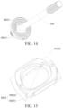
- the rotation angle limiting device 30100 includes a rotating gear 3001 and a movable member 30302.
- the rotating gear 3001 is connected to the second transmission portion 200 and rotates with the second transmission portion 200.
- a first limiting structure 30012 is arranged on the rotating gear 3001, and a second limiting structure 3003 is arranged on the movable member 30302.
- the rotating gear 3001 drives the movable member 30302 to move, to cause the first limiting structure 30012 abuts against the second limiting structure 3003.
- the second limiting structure 3003 includes a first limiting sub-structure 30031 and a second limiting sub-structure 30032, and the first limiting sub-structure 30031 and the second limiting sub-structure 30032 limits a maximum rotation angle of the rotating gear 3001 by stopping the first limiting structure 30012.
- the rotating gear 3001 and the second transmission portion 200 may be fixed in a circumferential direction of the second transmission portion 200, and the rotating gear 3001 and the second transmission portion 200 may relatively move in an axial direction of the second transmission portion 200.
- the rotating gear 3001 and the second transmission portion 200 may be connected by a spline, or the rotating gear 3001 and the second transmission portion 200 may be fitted by a tooth and a toothed groove.
- the tooth meshes with the toothed groove, and when the second transmission portion 200 moves to the engaged position, the tooth is disengaged from the toothed groove.
- first limiting sub-structure 30031 and the second limiting sub-structure 30032 may be arranged at intervals in a circumferential direction of the movable member 30302, and the first limiting structure 30012 is located between the first limiting sub-structure 30031 and the second limiting sub-structure 30032.
- the second transmission portion 200 is located at the disengaged position, viewed from above the vehicle, when the second transmission portion 200 rotates counterclockwise (that is, rotates left) to a limit position, the first limiting structure 30012 abuts against the first limiting sub-structure 30031; and when the second transmission portion 200 rotates clockwise (for example, rotates right) to a limit position, the first limiting structure 30012 abuts against the second limiting sub-structure 30032.
- Arrangement of the first limiting structure 30012 and the second limiting structure 3003 facilitates limitation on a rotation angle of the second transmission portion 200 at the disengaged position, and such a limiting manner is a mechanical limitation without energy consumption.
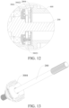
- the rotating gear 3001 is provided with a spiral groove 30011, a guide shaft 30021 is arranged on the movable member 30302, the guide shaft 30021 movably fits into the spiral groove 30011, and when moving with the second transmission portion 200, the rotating gear 3001 drives the movable member 30302 to move through the guide shaft 30021.
- the guide shaft 30021 moves relative to the spiral groove 30011, and since the guide shaft 30021 is arranged on the movable member 30302, the guide shaft 30021 drives the movable member 30302 to move relative to the fixed member 3004. In this way, the movable member 30302 moves relative to the housing 600 in a radial direction of the second transmission portion 200, and therefore, when the clutch apparatus 1 is in a decoupled state, the maximum rotation angle of the steering wheel is greater than 360°.
- the vehicle includes the vehicle steering system according to the embodiments of the present disclosure.
- the vehicle according to the embodiments of the present disclosure by using the vehicle steering system according to the foregoing embodiment of the present disclosure, can transmit steering torque and stop transmitting steering torque with low costs and flexible arrangement.
Landscapes
- Engineering & Computer Science (AREA)
- Mechanical Engineering (AREA)
- Chemical & Material Sciences (AREA)
- Combustion & Propulsion (AREA)
- Transportation (AREA)
- General Engineering & Computer Science (AREA)
- Mechanical Operated Clutches (AREA)
- Steering Controls (AREA)
- Power Steering Mechanism (AREA)
- Arrangement And Mounting Of Devices That Control Transmission Of Motive Force (AREA)
Abstract
Description
- The present disclosure is proposed based on and claims priority to
Chinese Patent Application Nos. 202011630575.3 202011630591.2, both filed on December 30, 2020 - The present disclosure relates to the field of vehicle technologies, and more specifically, to a clutch apparatus, a vehicle steering system, and a vehicle.
- Vehicles in the related art are usually equipped with a vehicle steering system for controlling a driving direction of the vehicle. However, a function of the vehicle steering system is single. The steering system always transmits steering torque, and cannot stop transmitting steering torque. The wheels and the steering wheel are always linked. With the improvement of emerging functions such as in-vehicle multimedia function and automatic driving function, the vehicle steering system can no longer match these emerging functions, resulting in poor applicability and user experience.
- The present disclosure is intended to resolve at least one of the technical problems in the related art. Therefore, an objective of the present disclosure is to provide a clutch apparatus, and the clutch apparatus can transmit and stop transmitting steering torque with low costs and flexible arrangement.
- The present disclosure further provides a vehicle steering system having the clutch apparatus.
- The present disclosure further provides a vehicle having the vehicle steering system.
- To achieve the foregoing objective, a clutch apparatus is provided according to embodiments of the present disclosure. The clutch apparatus includes: a first transmission portion and a second transmission portion, where the second transmission portion is movable between an engaged position and a disengaged position, the second transmission portion is engaged with the first transmission portion and transmits torque at the engaged position, and the second transmission portion is disengaged from the first transmission portion and stop transmitting torque at the disengaged position; a sleeve, sleeved on the second transmission portion; and a driving mechanism, including a driving apparatus and a linkage mechanism, where the linkage mechanism is in drive connection with the driving apparatus and the sleeve separately, the driving apparatus drives the linkage mechanism to move, to drive, through the sleeve, the second transmission portion to move between the engaged position and the disengaged position.
- According to the clutch apparatus in the embodiments of the present disclosure, the driving mechanism includes a driving apparatus and a linkage mechanism, where the linkage mechanism is in drive connection with the driving apparatus and the sleeve separately, and the driving apparatus drives the linkage mechanism to swing, to drive, through the sleeve, the second transmission portion to move between the engaged position and the disengaged position. In this way, the second transmission portion can move through the driving apparatus, so that steering torque can be transmitted and transmitting steering torque can be stopped.
- By arranging the linkage mechanism, while a driving force is transmitted between the driving apparatus and the second transmission portion, the linkage mechanism can increase a force for driving the second transmission portion to move, and therefore, requirements for the driving force outputted by the driving apparatus can be reduced, and costs of the driving apparatus are reduced. In addition, the linkage mechanism can increase movement travel of the second transmission portion, and can transmit the driving force in a long distance between the driving apparatus and the second transmission portion, improving arrangement flexibility of the second transmission portion, the sleeve, and the driving mechanism.
- The clutch apparatus according to the embodiments of the present disclosure can transmit steering torque and stop transmitting steering torque with low costs and flexible arrangement.
- According to some specific embodiments of the present disclosure, there are a first hinge point and a second hinge point between the linkage mechanism and the sleeve, and a connection line between the first hinge point and the second hinge point passes through a center of a cross section of the sleeve.
- According to some specific embodiments of the present disclosure, the cross section of the sleeve is annular, and the first hinge point and the second hinge point are arranged opposite to each other in a radial direction of the sleeve.
- According to some specific embodiments of the present disclosure, the clutch apparatus further includes: a third transmission portion, where the second transmission portion is connected to the third transmission portion, the second transmission portion cooperates with the third transmission portion to transmit torque, and the second transmission portion is movable relative to the third transmission portion between the engaged position and the disengaged position.
- According to some specific embodiments of the present disclosure, the third transmission portion is constructed to include a cavity, and the second transmission portion extends into the cavity; and one of an inner circumferential surface of the third transmission portion and an outer circumferential surface of the second transmission portion is provided with a slide groove and the other is provided with a slide rail, the slide groove and the slide rail both extend in an axial direction of the first transmission portion and the second transmission portion, and the slide rail into with the slide groove.
- According to some specific embodiments of the present disclosure, the second transmission portion includes: a shaft portion; a head portion, connected to an end of the shaft portion facing toward the first transmission portion, where when the second transmission portion is at the engaged position, the head portion is engaged with the first transmission portion; and when the second transmission portion is at the disengaged position, the head portion is disengaged from the first transmission portion.
- According to some specific embodiments of the present disclosure, one of the first transmission portion and the second transmission portion is constructed to include a flange and the other is constructed to include a groove, and a cross section of the flange and a cross section of the groove are constructed into non-circular shapes adapted to each other, where when the second transmission portion is at the engaged position, the flange extends into the groove; and when the second transmission portion is at the disengaged position, the flange is disengaged from the groove.
- According to some specific embodiments of the present disclosure, the clutch apparatus further includes: a housing, where at least a part of the first transmission portion, at least a part of the second transmission portion, and the sleeve are arranged in the housing, and the driving mechanism is mounted on the housing.
- According to some specific embodiments of the present disclosure, the first transmission portion is supported on the housing by a first bearing; the second transmission portion is supported on the sleeve by a second bearing; and the sleeve is supported on the housing by a third bearing.
- According to some specific embodiments of the present disclosure, the clutch apparatus further includes: an elastic member, acting on the sleeve and providing an elastic force for constantly pushing the second transmission portion toward the engaged position.
- According to some specific embodiments of the present disclosure, the clutch apparatus further includes: a spring seat, sleeved on the second transmission portion and mounted in the sleeve; and a spring sleeve, sleeved on the second transmission portion and mounted in the housing, where the elastic member is a spring sleeved on the second transmission portion, and one end of the elastic member abuts against the spring seat and an other end abuts against the interior of the spring sleeve.
- According to some specific embodiments of the present disclosure, the linkage mechanism is hingedly connected to the sleeve and the spring seat by a hinge shaft, and the housing is provided with a strip-shaped hole for the hinge shaft to pass through.
- According to some specific embodiments of the present disclosure, the driving mechanism includes: a transmission mechanism, where the driving apparatus is in drive connection with the linkage mechanism through the transmission mechanism, the driving apparatus is hingedly connected to the housing, and the linkage mechanism is separately hingedly connected to the transmission mechanism, the housing, and the sleeve.
- According to some specific embodiments of the present disclosure, the linkage mechanism includes: a first swing connecting rod, where one end of the first swing connecting rod is hingedly connected to the transmission mechanism, and an other end of the first swing connecting rod is hingedly connected to the sleeve; a second swing connecting rod, where one end of the second swing connecting rod is hingedly connected to the transmission mechanism, and an other end of the second swing connecting rod is hingedly connected to the sleeve; and a longitudinal connecting rod, where one end of the longitudinal connecting rod is hingedly connected to the housing, and an other end of the longitudinal connecting rod is hingedly connected to the first swing connecting rod and the second swing connecting rod.
- According to some specific embodiments of the present disclosure, the transmission mechanism includes: an output screw rod, where the output screw rod is in drive connection with the driving apparatus; and an output nut, where the output nut is sleeved on the output screw rod and threadedly fits onto the output screw rod, where the end of the first swing connecting rod and the end of the second swing connecting rod are hingedly connected to the output nut.
- According to some specific embodiments of the present disclosure, the transmission mechanism further includes: a transmission screw rod, where the driving apparatus is a motor, and the transmission screw rod is in drive connection with a motor shaft of the motor; a first transmission gear, where the first transmission gear meshes with the transmission screw rod; and a second transmission gear, where the second transmission gear is connected to the first transmission gear and rotates with the first transmission gear, and the second transmission gear meshes with the output screw rod.
- According to some specific embodiments of the present disclosure, the first swing connecting rod and the second swing connecting rod are separately hingedly connected to two radial sides of the output nut respectively, and a hinge axis of the first swing connecting rod coincides with a hinge axis of the second swing connecting rod and is perpendicular to a radial direction of the output nut.
- According to some specific embodiments of the present disclosure, the longitudinal connecting rod is hingedly connected to between two ends of the first swing connecting rod and between two ends of the second swing connecting rod, and a position of a hinge joint between the longitudinal connecting rod and the first swing connecting rod in a length direction of the first swing connecting rod is the same as the position of a hinge joint between the longitudinal connecting rod and the second swing connecting rod in a length direction of the second swing connecting rod.
- According to the embodiments of the present disclosure, a vehicle steering system is provided, including: the clutch apparatus according to any foregoing embodiment of the present disclosure; a steering wheel, where the steering wheel is in drive connection with one of the first transmission portion and the second transmission portion; and a steering device, where the steering device is in drive connection with the other of the first transmission portion and the second transmission portion.
- The vehicle steering system according to the embodiments of the present disclosure, by using the clutch apparatus according to any foregoing embodiment of the present disclosure, can transmit steering torque and stop transmitting steering torque with low costs and flexible arrangement.
- In some embodiments of the present disclosure, the vehicle steering system further includes a rotation angle limiting device, where the rotation angle limiting device is connected to one of the first transmission portion and the second transmission portion, and when the second transmission portion is at the disengaged position, the rotation angle limiting device limits a maximum rotation angle of the steering wheel by limiting a maximum rotation angle of one of the first transmission portion and the second transmission portion.
- In some embodiments of the present disclosure, the vehicle steering system further includes a rotation angle limiting device, where the rotation angle limiting device is connected to one of the first transmission portion and the second transmission portion, and when the second transmission portion is at the disengaged position, the rotation angle limiting device limits a maximum rotation angle of the steering wheel by limiting a maximum rotation angle of one of the first transmission portion and the second transmission portion.
- According to the embodiments of the present disclosure, a vehicle is provided, including the vehicle steering system according to any foregoing embodiment of the present disclosure.
- The vehicle according to the embodiments of the present disclosure, by using the vehicle steering system according to any foregoing embodiment of the present disclosure, can transmit steering torque and stop transmitting steering torque with low costs and flexible arrangement.
- Other aspects and advantages of the present disclosure will be given in the following descriptions, some of which will become apparent from the following descriptions or may be learned from practices of the present disclosure.
- The foregoing and/or additional aspects and advantages of the present disclosure will become apparent and comprehensible from the following descriptions of the embodiments with reference to the accompanying drawings, where
-
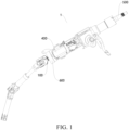
FIG. 1 is a schematic structural diagram of a clutch apparatus according to an embodiment of the present disclosure; -
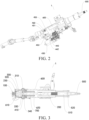
FIG. 2 is a schematic structural diagram of a clutch apparatus from another perspective according to an embodiment of the present disclosure; -
FIG. 3 is a sectional view of a clutch apparatus according to an embodiment of the present disclosure, where a second transmission portion is located at an engaged position; -
FIG. 4 is a sectional view of a clutch apparatus according to an embodiment of the present disclosure, where a second transmission portion is located at a disengaged position; -
FIG. 5 is a schematic structural diagram of a clutch apparatus according to an embodiment of the present disclosure, where a second transmission portion is located at a disengaged position; -
FIG. 6 is a schematic structural diagram of a clutch apparatus according to an embodiment of the present disclosure, where a second transmission portion is located at an engaged position; -
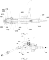
FIG. 7 is a sectional view of a clutch apparatus from another perspective according to an embodiment of the present disclosure, where a second transmission portion is located at an engaged position; -
FIG. 8 is a sectional view of a clutch apparatus from another perspective according to an embodiment of the present disclosure, where a second transmission portion is located at a disengaged position; -
FIG. 9 is a schematic structural diagram of a first transmission portion and a second transmission portion of a clutch apparatus according to an embodiment of the present disclosure; -
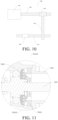
FIG. 10 is a schematic structural diagram of a transmission mechanism of a clutch apparatus according to an embodiment of the present disclosure; -
FIG. 11 is a sectional view of a rotation angle limiting device of a vehicle steering system according to an embodiment of the present disclosure; -
FIG. 12 is another sectional view of a rotation angle limiting device of a vehicle steering system according to an embodiment of the present disclosure; -
FIG. 13 is a schematic structural diagram of a fixed member of a rotation angle limiting device of a vehicle steering system according to an embodiment of the present disclosure; -
FIG. 14 is a schematic structural diagram of a spiral groove and a first limiting structure of a rotation angle limiting device of a vehicle steering system according to an embodiment of the present disclosure; -
FIG. 15 is a schematic structural diagram of a movable member of a rotation angle limiting device of a vehicle steering system according to an embodiment of the present disclosure; -
FIG. 16 is a schematic assembly diagram of a movable member and a fixed member of a rotation angle limiting device of a vehicle steering system according to an embodiment of the present disclosure; and -
FIG. 17 is a schematic structural diagram of a fixed member of a rotation angle limiting device of a vehicle steering system according to an embodiment of the present disclosure; -
-
clutch apparatus 1, -
first transmission portion 100,flange 110, -
second transmission portion 200,shaft portion 220,head portion 230,groove 240, -
sleeve 300,first hinge point 310,second bearing 330,third bearing 320,spring seat 340, -
driving mechanism 400,second hinge point 410, drivingapparatus 430,transmission mechanism 440,output screw rod 441,output nut 442,transmission screw rod 443,first transmission gear 444,second transmission gear 445,linkage mechanism 450, firstswing connecting rod 451, secondswing connecting rod 452, longitudinal connectingrod 453, strip-shapedhole 455,hinge shaft 460, -
third transmission portion 500,cavity 510,fourth bearing 520, -
housing 600,first bearing 610,spring sleeve 620, -
elastic member 700, - rotation
angle limiting device 30100, rotatinggear 3001, fixedmember 3004,fitting groove 30041,spiral groove 30011, first limitingstructure 30012,movable member 30302,guide shaft 30021, second limitingstructure 3003, first limitingsub-structure 30031, and second limitingsub-structure 30032. - The following describes embodiments of the present disclosure in detail. Examples of the embodiments are shown in the accompanying drawings, and same or similar reference numerals in all the accompanying drawings indicate same or similar components or components having same or similar functions. The embodiments described below with reference to the accompanying drawings are exemplary and used merely for explaining the present disclosure, and should not be construed as a limitation on the present disclosure.
- In the descriptions of the present disclosure, it should be understood that, orientations or position relationships indicated by terms such as "center", "longitudinal", "transverse", "length", "width", "thickness", "up", "down", "front", "back", "left", "right", "vertical", "horizontal", "top", "bottom", "inner", "outer", "clockwise", "counterclockwise", "axial", "radial", and "circumferential" are orientations or position relationship shown based on the accompanying drawings, and are merely used for describing the present disclosure and simplifying the descriptions, rather than indicating or implying that the apparatus or element should have a particular orientation or be constructed and operated in a particular orientation, and therefore, should not be construed as a limitation on the present disclosure.
- In the descriptions of the present disclosure, "a number of means two or more than two, and "several" means one or more.
- A
clutch apparatus 1 according to the embodiments of the present disclosure is described below with reference to the accompanying drawings. - As shown in
FIG. 1 to FIG. 10 , theclutch apparatus 1 includes afirst transmission portion 100, asecond transmission portion 200, asleeve 300, and adriving mechanism 400. - The
first transmission portion 100 and thesecond transmission portion 200 may be constructed into axial structures. Thesecond transmission portion 200 is movable between an engaged position and a disengaged position, thesecond transmission portion 200 is engaged with thefirst transmission portion 100 and transmits torque at the engaged position, and thesecond transmission portion 200 is disengaged from thefirst transmission portion 100 and stops transmitting torque at the disengaged position. Thesleeve 300 is sleeved on thesecond transmission portion 200. Thedriving mechanism 400 includes adriving apparatus 430 and alinkage mechanism 450. Thelinkage mechanism 450 is in drive connection with the drivingapparatus 430 and thesleeve 300 separately, and thedriving apparatus 430 drives thelinkage mechanism 450 to swing, to drive, through thesleeve 300, thesecond transmission portion 200 to move between the engaged position and the disengaged position. - For example, the
sleeve 300 and thesecond transmission portion 200 can synchronously move in an axial direction of thesecond transmission portion 200 and can rotate relative to each other in a circumferential direction of thesecond transmission portion 200. That is, thesleeve 300 and thesecond transmission portion 200 can synchronously move in an axial direction of thesecond transmission portion 200 and can rotate relative to each other in a circumferential direction of thesecond transmission portion 200. - The
clutch apparatus 1 according to the embodiments of the present disclosure makes thesecond transmission portion 200 movable between the engaged position and the disengaged position, thesecond transmission portion 200 is engaged with thefirst transmission portion 100 and transmits the torque at the engaged position, and thesecond transmission portion 200 is disengaged from thefirst transmission portion 100 and stops transmitting torque at the disengaged position. That is, when thefirst transmission portion 100 and thesecond transmission portion 200 are at the engaged position, thefirst transmission portion 100 and thesecond transmission portion 200 can synchronously rotate, as shown inFIG. 3 andFIG. 7 ; and when thefirst transmission portion 100 and thesecond transmission portion 200 are at the disengaged position, thefirst transmission portion 100 and thesecond transmission portion 200 can separately rotate, in other words, when thefirst transmission portion 100 rotates, thesecond transmission portion 200 may rotate or may not rotate. Similarly, when thesecond transmission portion 200 rotates, thefirst transmission portion 100 may rotate or may not rotate, as shown inFIG. 4 andFIG. 8 . - For example, the
clutch apparatus 1 is applied to a vehicle steering system, and when thesecond transmission portion 200 is at the engaged position, the vehicle steering system can normally transmit moment of a steering wheel operated by a driver to a steering device. - When the
second transmission portion 200 is at the disengaged position, the steering wheel and the steering device are disconnected. In this case, the steering wheel is rotated, and the steering device is not driven to move with the steering wheel, but the steering wheel can still drive components, such as a combined switch, a clock spring, and an angle sensor, to normally operate. The steering wheel in this state may be used as a simulator of vehicle driving and may output a rotation angle signal of the steering wheel to an in-vehicle device or an external device. For example, in this case, the steering wheel may be used for control in-vehicle multimedia and playing a racing game. In addition, movement of the steering device in this case does not drive the steering wheel to move. For example, when the vehicle is in a remote driving state or an autonomous driving state, the steering device moves to control the entire vehicle to steer, and the steering wheel may not rotate with the steering device, to ensure safety of the driver and ride comfort. - In addition, the
sleeve 300 is sleeved on thesecond transmission portion 200, thedriving mechanism 400 includes the drivingapparatus 430 and thelinkage mechanism 450, thelinkage mechanism 450 is in drive connection with the drivingapparatus 430 and thesleeve 300 separately, and thedriving apparatus 430 drives thelinkage mechanism 450 to move, for example, the drivingapparatus 430 drives thelinkage mechanism 450 to swing, to drive, through thesleeve 300, thesecond transmission portion 200 to move between the engaged position and the disengaged position. In this way, thesecond transmission portion 200 can move through the drivingapparatus 430, so that steering torque can be transmitted and transmitting steering torque can be stopped. - In addition, by arranging the
linkage mechanism 450, while a driving force is transmitted between the drivingapparatus 430 and thesecond transmission portion 200, thelinkage mechanism 450 can increase a force for driving thesecond transmission portion 200 to move, and therefore, requirements for the driving force outputted by the drivingapparatus 430 can be reduced, and costs of the drivingapparatus 430 are reduced. In addition, thelinkage mechanism 450 can increase movement travel of thesecond transmission portion 200 and can transmit the driving force in a long distance between the drivingapparatus 430 and thesecond transmission portion 200, and with diversity of force transmission of thelinkage mechanism 450, while thesleeve 300 and thesecond transmission portion 200 are driven to move according to a predetermined path, requirements for position of the drivingapparatus 430 are reduced, and arrangement flexibility of the drivingapparatus 430 is improved. - By arranging the
sleeve 300, thesleeve 300 and thesecond transmission portion 200 can synchronously move in the axial direction of thesecond transmission portion 200, and thedriving apparatus 430 and thesecond transmission portion 200 can rotate in the circumferential direction of thesecond transmission portion 200 in a same manner, so that thesecond transmission portion 200 can be driven, through thesleeve 300, to move in the axial direction, and thesecond transmission portion 200 can rotate without being affected by thesleeve 300. - In this way, the
clutch apparatus 1 according to the embodiments of the present disclosure can transmit steering torque and stop transmitting steering torque with low costs and flexible arrangement. - According to some specific embodiments of the present disclosure, as shown in
FIG. 3 andFIG. 4 , there are afirst hinge point 310 and asecond hinge point 410 between thelinkage mechanism 450 and thesleeve 300, and a connection line between thefirst hinge point 310 and thesecond hinge point 410 passes through a center of a cross section of thesleeve 300. In this way, a force arm between thefirst hinge point 310 and thesleeve 300 and a force arm between thesecond hinge point 410 and thesleeve 300 are located at a same straight line. That is, a moment of the entireclutch apparatus 1 may be symmetrical relative to a central axis of theclutch apparatus 1, which helps to remove a turning moment of thesleeve 300, ensures that thesleeve 300 moves in an extending direction of thesleeve 300, and increases movement smoothness of thesecond transmission portion 200, preventing thesecond transmission portion 200 from being stuck during movement. - It needs to be noted that the cross section of the
sleeve 300 is a cross section perpendicular to an axial direction of thesleeve 300. - For example, a plane on which a cross section of the
sleeve 300 is located passes through thefirst hinge point 310 and thesecond hinge point 410 at the same time, the connection line between thefirst hinge point 310 and thesecond hinge point 410 passes through a center of the cross section, and a distance from thefirst hinge point 310 to the center of the cross section and a distance from thesecond hinge point 410 to the center of the cross section may be the same. - According to some specific embodiments of the present disclosure, as shown in
FIG. 1 andFIG. 2 , the cross section of thesleeve 300 is annular, such as circular. Thefirst hinge point 310 and thesecond hinge point 410 are arranged opposite to each other in a radial direction of thesleeve 300. Such shape rules of thesleeve 300 is for ease of production and processing, and disassembly and replacement. In addition, theentire sleeve 300 is uniformly forced, which avoids stress concentration, and further ensures movement smoothness of thesecond transmission portion 200. Certainly, it may be understood that, a shape of the cross section of thesleeve 300 is not limited to this, for example, the shape may alternatively be square. - According to some specific embodiments of the present disclosure, as shown in
FIG. 3 andFIG. 4 , andFIG. 7 andFIG. 8 , theclutch apparatus 1 further includes athird transmission portion 500. - The
third transmission portion 500 may alternatively be constructed into an axial structure, thesecond transmission portion 200 is connected to thethird transmission portion 500, and thesecond transmission portion 200 cooperates with thethird transmission portion 500 to transmit torque. That is, thesecond transmission portion 200 and thethird transmission portion 500 can synchronously rotate to transmit the torque, and thesecond transmission portion 200 is movable relative to thethird transmission portion 500 between the engaged position and the disengaged position (that is, movable in an axial direction). Thethird transmission portion 500 may be fixed to the steering wheel. - Therefore, the
second transmission portion 200 and thethird transmission portion 500 can synchronously rotate, that is, torque can be transmitted between thesecond transmission portion 200 and thethird transmission portion 500, and thesecond transmission portion 200 and thethird transmission portion 500 can independently move in the axial direction of the second transmission portion 200 (an axial direction of the third transmission portion 500), that is, when thesecond transmission portion 200 moves in the axial direction of thesecond transmission portion 200, thethird transmission portion 500 does not move. In this way, when thesecond transmission portion 200 is switchable between an engaged state and a disengaged state, the steering wheel can continue to synchronously rotate with thethird transmission portion 500, ensuring that a position of the steering wheel is stable in the axial direction of thethird transmission portion 500, so that the steering wheel can be used to input steering torque, and regardless of a moving manner of thesecond transmission portion 200 in the axial direction, thethird transmission portion 500 can remove the movement, and then the steering wheel does not move in the axial direction. - In some embodiments of the present disclosure, the
third transmission portion 500 is constructed to include acavity 510, thesecond transmission portion 200 extends into thecavity 510, one of an inner circumferential surface of thethird transmission portion 500 and an outer circumferential surface of thesecond transmission portion 200 is provided with a slide groove and the other is provided with a slide rail, the slide groove and the slide rail both extend in the axial direction of thefirst transmission portion 100 and thesecond transmission portion 200, and the slide rail fits into the slide groove. The slide groove and the slide rail may be splines fitting each other. The axial direction of thefirst transmission portion 100, the axial direction of thesecond transmission portion 200, and thethird transmission portion 500 may be parallel to each other. In this way, torque can be transmitted between thesecond transmission portion 200 and thethird transmission portion 500, and thesecond transmission portion 200 and thethird transmission portion 500 can relatively move in the axial direction with easy processing and low difficulty. - According to some specific embodiments of the present disclosure, as shown in
FIG. 9 , thesecond transmission portion 200 includes ashaft portion 220 and ahead portion 230. Thehead portion 230 is connected to an end of theshaft portion 220 facing toward thefirst transmission portion 100. For example, thehead portion 230 and theshaft portion 220 may be fixed by welding. When thesecond transmission portion 200 is at the engaged position, thehead portion 230 is engaged with thefirst transmission portion 100; and when thesecond transmission portion 200 is at the disengaged position, thehead portion 230 is disengaged from thefirst transmission portion 100. - For example, a cross-sectional area of the
head portion 230 may be greater than a cross-sectional area of theshaft portion 220. In this way, when thesecond transmission portion 200 is located at the engaged position, by arranging thehead portion 230, the torque is more stably transmitted between thesecond transmission portion 200 and thefirst transmission portion 100. In addition, by arranging theshaft portion 220, production cost of thesecond transmission portion 200 can be reduced, assembling space required for thesecond transmission portion 200 is reduced, and it is beneficial to miniaturization of theclutch apparatus 1. - In some embodiments of the present disclosure, one of the
first transmission portion 100 and thesecond transmission portion 200 is constructed to include aflange 110, and the other is constructed to include agroove 240. A cross section of theflange 110 and a cross section of thegroove 240 are constructed into non-circular adapted to each other. For example, theflange 110 is formed on an end surface of thehead portion 230 facing toward thefirst transmission portion 100, thegroove 240 is formed on an end surface of thefirst transmission portion 100 facing toward thehead portion 230, and the cross section of theflange 110 and the cross section of thegroove 240 may be constructed into a cross shape, a rectangle, a wedge shape, a circular arc, an involute curve, or other curves. - When the
second transmission portion 200 is at the engaged position, theflange 110 extends into thegroove 240; and when thesecond transmission portion 200 is at the disengaged position, theflange 110 is disengaged from thegroove 240. In this way, when thefirst transmission portion 100 and thesecond transmission portion 200 are in an engaged state, thefirst transmission portion 100 is stably connected to thesecond transmission portion 200 to stably transmit torque. - According to some specific embodiments of the present disclosure, as shown in
FIG. 3 andFIG. 4 , andFIG. 7 andFIG. 8 , theclutch apparatus 1 further includes ahousing 600. At least a part of thefirst transmission portion 100, at least a part of thesecond transmission portion 200, and thesleeve 300 are arranged in thehousing 600. For example, a part of thefirst transmission portion 100, thesecond transmission portion 200, thesleeve 300, and a part of thethird transmission portion 500 may be arranged in thehousing 600. Thedriving mechanism 400 is mounted outside thehousing 600. - By arranging the
housing 600, on one hand, assembling position for thedriving mechanism 400 is provided, on the other hand, a direct contact area between thefirst transmission portion 100 and thesecond transmission portion 200 and the outside can be reduced, and damage possibility of thefirst transmission portion 100 and thesecond transmission portion 200 is reduced. - According to some specific embodiments of the present disclosure, as shown in
FIG. 3 andFIG. 4 , andFIG. 7 andFIG. 8 , thefirst transmission portion 100 is supported on thehousing 600 by afirst bearing 610, thesecond transmission portion 200 is supported on thesleeve 300 by asecond bearing 330, thesleeve 300 is supported on thehousing 600 by athird bearing 320, and an end of thethird transmission portion 500 away from thesecond transmission portion 200 may be supported in thehousing 600 by afourth bearing 520. - For example, the
third bearing 320 may be a slide bearing, reducing sliding friction between thesleeve 300 and thehousing 600. In this way, connection between thefirst transmission portion 100 and thehousing 600 is stable while facilitating relative rotation, connection between thesleeve 300 and thesecond transmission portion 200 is stable while facilitating relative rotation, connection between thesleeve 300 and thehousing 600 is stable while facilitating relative rotation, and connection between thethird transmission portion 500 and thehousing 600 is stable while facilitating relative rotation. - In some embodiments of the present disclosure, an inner circumferential surface of the
sleeve 300 and the outer circumferential surface of thesecond transmission portion 200 may be constructed to include a structure such as stairs, and therefore, relative positions of thesleeve 300, thesecond transmission portion 200, and thesecond bearing 330 in an axial direction of theclutch apparatus 1 are limited, ensuring that thesleeve 300 and thesecond transmission portion 200 can simultaneously move in the axial direction of theclutch apparatus 1. - According to some specific embodiments of the present disclosure, as shown in
FIG. 3 andFIG. 4 , andFIG. 7 andFIG. 8 , theclutch apparatus 1 further includes anelastic member 700. Theelastic member 700 acts on thesleeve 300, and theelastic member 700 provides an elastic force for constantly pushing thesecond transmission portion 200 toward the engaged position. In this way, on one hand, a thrust force for pushing thesecond transmission portion 200 toward the engaged position is increased, thereby increasing movement smoothness of thesecond transmission portion 200 toward the engaged position; on the other hand, when thesecond transmission portion 200 is located at the engaged position, contact between thefirst transmission portion 100 and thesecond transmission portion 200 is closer, connection is stable without energy consumption, and a fit clearance is further reduced. - In some embodiments of the present disclosure, the
clutch apparatus 1 further includes aspring seat 340 and aspring sleeve 620. Thespring seat 340 is sleeved on thesecond transmission portion 200 and mounted in thesleeve 300, thespring sleeve 620 is sleeved on thesecond transmission portion 200 and mounted in thehousing 600. Theelastic member 700 is a spring sleeved on thesecond transmission portion 200, and one end of theelastic member 700 abuts against thespring seat 340 and an other end abuts against the interior of thespring sleeve 620. For example, a central axis of thespring seat 340, a central axis of thespring sleeve 620, a central axis of theelastic member 700, and a central axis of thesecond transmission portion 200 may coincide. - In this way, on one hand, an elastic force for constantly pushing the
second transmission portion 200 toward the engaged position is easy to be provided by theelastic member 700; on the other hand, a moment of the entiresecond transmission portion 200 may keep symmetrical relative to the central axis of the second transmission portion, so as to ensure that a movement direction and an extending direction of thesecond transmission portion 200 is the same, thereby ensuring movement smoothness of thesecond transmission portion 200. In addition, by arranging thespring seat 340 and thespring sleeve 620, it is ensured that the elastic force of theelastic member 700 can be transferred to thesleeve 300 and thehousing 600, and a position of theelastic member 700 is stable. - According to some specific embodiments of the present disclosure, as shown in
FIG. 2 andFIG. 5 , thelinkage mechanism 450 is hingedly connected to thesleeve 300 and thespring seat 340 by ahinge shaft 460, and thehousing 600 is provided with a strip-shapedhole 455 for thehinge shaft 460 to pass through, so as to facilitate mounting of thehinge shaft 460. - In this way, connection of the
linkage mechanism 450 with thesleeve 300 and thespring seat 340 is stable, and it is easy for thelinkage mechanism 450 to swing relative to thesleeve 300 and thespring seat 340. In addition, thehinge shaft 460 can fix relative positions of thespring seat 340 and thesleeve 300, in this way, thehinge shaft 460 may be used to fix axial positions of thespring seat 340 and thesleeve 300 at the same time, so that the elastic force of theelastic member 700 is more reliable and accurately acts on thesleeve 300. In addition, arrangement of the strip-shapedhole 455 is convenient for thehinge shaft 460 to pass through thehousing 600 and be hingedly connected to thesleeve 300, and thehinge shaft 460 can move in a length direction of the strip-shapedhole 455, so that when thesecond transmission portion 200 is driven to move, thehinge shaft 460 can move. - According to some specific embodiments of the present disclosure, as shown in
FIG. 5 to FIG. 7 , thedriving mechanism 400 further includes atransmission mechanism 440. The drivingapparatus 430 is hingedly connected to thehousing 600, the drivingapparatus 430 is in drive connection with thelinkage mechanism 450 through thetransmission mechanism 440, and thelinkage mechanism 450 is separately hingedly connected to thetransmission mechanism 440, thehousing 600, and thesleeve 300. - In this way, the
driving mechanism 400 adopts thetransmission mechanism 440 to transfer a driving force of the drivingapparatus 430 to thelinkage mechanism 450. Transfer of the driving force is stable, and after the driving force acts on thetransmission mechanism 440, a direction of a force outputted by thetransmission mechanism 440 may be different from the driving force of the drivingapparatus 430. Therefore, the direction of a force outputted by thetransmission mechanism 440 can better meet requirements for movement of thelinkage mechanism 450, increasing arrangement flexibility of thedriving mechanism 400. - In some embodiments of the present disclosure, the
linkage mechanism 450 includes a firstswing connecting rod 451, a secondswing connecting rod 452, and a longitudinal connectingrod 453. One end of the firstswing connecting rod 451 is hingedly connected to thetransmission mechanism 440, an other end of the firstswing connecting rod 451 is hingedly connected to thesleeve 300. One end of the secondswing connecting rod 452 is hingedly connected to thetransmission mechanism 440, an other end of the secondswing connecting rod 452 is hingedly connected to thesleeve 300. One end of the longitudinal connectingrod 453 is hingedly connected to thehousing 600, and an other end of the longitudinal connectingrod 453 is hingedly connected to the firstswing connecting rod 451 and the secondswing connecting rod 452. - For example, the first
swing connecting rod 451 and the secondswing connecting rod 452 may be located on two opposite sides of thesleeve 300. A distance from a position of each swing connecting rod connected to the longitudinal connectingrod 453 to a position of the swing connecting rod hingedly connected to thesleeve 300 may be less than a distance from the position of each swing connecting rod connected to the longitudinal connectingrod 453 to a position of the swing connecting rod hingedly connected to thetransmission mechanism 440. - Two swing connecting rods are arranged to act on the
sleeve 300, enabling theentire sleeve 300 to be forced more uniformly, so as to improve movement stability of thesleeve 300. In addition, arrangement of the longitudinal connectingrod 453 facilitates synchronous movement of the firstswing connecting rod 451 and the secondswing connecting rod 452, and two ends of the firstswing connecting rod 451 and two ends of the secondswing connecting rod 452 can swing with the longitudinal connectingrod 453 as a pivot point. Each swing connecting rod can form a structure similar to a "seesaw", so that a force that thelinkage mechanism 450 acts on thesleeve 300 may be greater than the driving force of the drivingapparatus 430. In addition, with arrangement of thelinkage mechanism 450, the drivingapparatus 430 does not need to be directly connected to thesleeve 300, which helps to reduce a volume of theentire driving mechanism 400 in the axial direction of theclutch apparatus 1. - In some embodiments of the present disclosure, the
transmission mechanism 440 includes anoutput screw rod 441 and anoutput nut 442. Theoutput screw rod 441 is in drive connection with the drivingapparatus 430, theoutput nut 442 is sleeved on theoutput screw rod 441 and threadedly fits onto theoutput screw rod 441. The one end of the firstswing connecting rod 451 and the one end of the secondswing connecting rod 452 are hingedly connected to theoutput nut 442. - For example, the driving
apparatus 430 can drive theoutput screw rod 441 to rotate. Theoutput screw rod 441 threadedly fits into theoutput nut 442, and therefore, when theoutput screw rod 441 rotates, theoutput nut 442 moves in an axial direction of theoutput screw rod 441, and in this case, theoutput nut 442 drives two swing connecting rods to swing, and then drives thesleeve 300 and thesecond transmission portion 200 to move in the axial direction of theclutch apparatus 1, to transform rotation of the drivingapparatus 430 into linear reciprocating motion of thesecond transmission portion 200. - As shown in
FIG. 10 , thetransmission mechanism 440 further includes atransmission screw rod 443, afirst transmission gear 444, and asecond transmission gear 445. The drivingapparatus 430 is a motor, and thetransmission screw rod 443 is in drive connection with a motor shaft of the motor, where a moving direction of thesleeve 300 in the axial direction of theclutch apparatus 1 can be controlled by a rotation direction of the motor shaft of the motor (that is, rotation in a forward direction and a reverse direction). Thefirst transmission gear 444 meshes with thetransmission screw rod 443, thesecond transmission gear 445 is connected to thefirst transmission gear 444 and rotates with thefirst transmission gear 444, and thesecond transmission gear 445 meshes with theoutput screw rod 441. - For example, the
first transmission gear 444 and thesecond transmission gear 445 may coaxially rotate. For example, thefirst transmission gear 444 and thesecond transmission gear 445 may be integrally formed, central axes of thefirst transmission gear 444 and thesecond transmission gear 445 may coincide, diameters of thefirst transmission gear 444 and thesecond transmission gear 445 may be different, and tooth types of thefirst transmission gear 444 and thesecond transmission gear 445 may be helical gears. - In this way, through transfer of the
first transmission gear 444 and thesecond transmission gear 445, a driving rotation speed and driving torque outputted by the drivingapparatus 430 is different from a rotation speed and torque received by theoutput screw rod 441. For example, the rotation speed of theoutput screw rod 441 may be less than the driving rotation speed outputted by the drivingapparatus 430, and the torque of theoutput screw rod 441 may be greater than the driving torque outputted by the drivingapparatus 430. In this case, thelinkage mechanism 450 moves at a relatively slow speed and is subjected to a relatively high driving force, which helps to improve movement stability of thelinkage mechanism 450. - According to some specific embodiments of the present disclosure, as shown in
FIG. 2 ,FIG. 5 , andFIG. 6 , the firstswing connecting rod 451 and the secondswing connecting rod 452 are separately hingedly connected to two radial sides of theoutput nut 442. A hinge axis of the firstswing connecting rod 451 coincides with a hinge axis of the secondswing connecting rod 452 and is perpendicular to an axial direction of theoutput nut 442. - A force arm between the first
swing connecting rod 451 and theoutput nut 442 and a force arm between the secondswing connecting rod 452 and theoutput nut 442 may be located in the same straight line, and the straight line is perpendicular to the axial direction of theoutput nut 442. In this way, when theoutput nut 442 drives the firstswing connecting rod 451 and the secondswing connecting rod 452 to swing, moments that the firstswing connecting rod 451 and the secondswing connecting rod 452 are subjected to from theoutput nut 442 are the same, so as to ensure that the firstswing connecting rod 451 and the secondswing connecting rod 452 synchronously move and have stable relative positions. - According to some specific embodiments of the present disclosure, as shown in
FIG. 5 andFIG. 6 , the longitudinal connectingrod 453 is hingedly connected to between two ends of the firstswing connecting rod 451 and between two ends of the secondswing connecting rod 452. A position of a hinge joint between the longitudinal connectingrod 453 and the firstswing connecting rod 451 in a length direction of the firstswing connecting rod 451 is the same as a position of a hinge joint between the longitudinal connectingrod 453 and the secondswing connecting rod 452 in a length direction of the secondswing connecting rod 452. - In this way, a motion amplitude of the first
swing connecting rod 451 and a motion amplitude of the secondswing connecting rod 452 are the same, so that a movement direction of thesleeve 300 is consistent with the axial direction to improve movement smoothness of theclutch apparatus 1. In addition, each swing connecting rod is easy to form a "seesaw" structure. - A vehicle steering system according to the embodiments of the present disclosure is described below with reference to the accompanying drawings. The vehicle steering system includes a
clutch apparatus 1, a steering wheel, and a steering device. - The steering wheel is in drive connection with one of a
first transmission portion 100 and asecond transmission portion 200, and the steering device is in drive connection with the other of thefirst transmission portion 100 and thesecond transmission portion 200. For example, the steering wheel is in drive connection with one of athird transmission portion 500 and thesecond transmission portion 200 and transmits torque, and the steering device is in drive connection with thefirst transmission portion 100 and transmits torque. - According to the vehicle steering system of the present disclosure, by using the
clutch apparatus 1 according to the foregoing embodiments of the present disclosure, rotation torque can be transmitted and transmitting rotation torque can be stopped with low costs and flexible arrangement. - In some embodiments of the present disclosure, the vehicle steering system further includes a rotation
angle limiting device 30100. The rotation angle limiting device is connected to one of thefirst transmission portion 100 and thesecond transmission portion 200. When thesecond transmission portion 200 is located at a disengaged position, the rotationangle limiting device 30100 limits a maximum rotation angle of the steering wheel by limiting a maximum rotation angle of one of thefirst transmission portion 100 and thesecond transmission portion 200. - For example, the
first transmission portion 100 is connected to the steering device such as a wheel, thesecond transmission portion 200 is connected to the steering wheel, thesecond transmission portion 200 is movable between an engaged position and the disengaged position. Thesecond transmission portion 200 is engaged with thefirst transmission portion 100 and transmits rotation torque of the steering wheel to the wheel at the engaged position, to implement linkage movement between the wheel and the steering wheel, for example, when the steering wheel is rotated to the left, the wheel is rotated to the left, and when the steering wheel is rotated to the right, the wheel is rotated to the right. Thesecond transmission portion 200 is disengaged from thefirst transmission portion 100 and stops transmitting rotation torque of the steering wheel to the wheel at the disengaged position, to implement separate rotation of the wheel and the steering wheel, for example, when the wheel is rotated to the left, the steering wheel may not be rotated, and when the steering wheel is rotated to the left, the wheel may not be rotated. - In addition, the rotation
angle limiting device 30100 is connected to thesecond transmission portion 200, and when thesecond transmission portion 200 is located at the disengaged position, the rotationangle limiting device 30100 limits a maximum rotation angle of the steering wheel by limiting a maximum rotation angle of thesecond transmission portion 200. In this way, theclutch apparatus 1 is separately arranged, it is convenient to transmit torque and stop transmitting torque between the steering wheel and the wheel, and when theclutch apparatus 1 is in a coupled state, limiting the maximum rotation angle of the steering wheel does not affect rotation of the wheel, ensuring normal driving of a vehicle. - In some embodiments of the present disclosure, as shown in
FIG. 11 andFIG. 12 , thesecond transmission portion 200 passes through the rotationangle limiting device 30100, a connection position of the rotationangle limiting device 30100 with thesecond transmission portion 200 is adjacent to an end of thesecond transmission portion 200 facing toward thefirst transmission portion 100. That is, a distance from the connection position of the rotationangle limiting device 30100 with thesecond transmission portion 200 to thefirst transmission portion 100 is less than a distance from the connection position of the rotationangle limiting device 30100 with thesecond transmission portion 200 to the steering wheel. A vehicle body has large space in which thefirst transmission portion 100 and thesecond transmission portion 200 is connected, and therefore, the rotationangle limiting device 30100 is arranged at an end of thesecond transmission portion 200 facing toward thefirst transmission portion 100, thereby reducing arrangement difficulty of the rotationangle limiting device 30100 and improving space utilization of the vehicle. Thesecond transmission portion 200 passes through the rotationangle limiting device 30100, facilitating circumferential limitation on thesecond transmission portion 200 and reducing occupied space. - In some embodiments of the present disclosure, as shown in
FIG. 13 , the rotationangle limiting device 30100 is located on a side of thehead portion 230 facing away from thefirst transmission portion 100. Therefore, space is fully utilized, and the rotationangle limiting device 30100 is connected to thesecond transmission portion 200 in an axial direction, facilitating transmission of limiting torque, so that the rotationangle limiting device 30100 limits the maximum rotation angle of thesecond transmission portion 200 more effectively. - According to some specific embodiments of the present disclosure, as shown in
FIG. 11 ,FIG. 14, and FIG. 15 , the rotationangle limiting device 30100 includes arotating gear 3001 and amovable member 30302. - The
rotating gear 3001 is connected to thesecond transmission portion 200 and rotates with thesecond transmission portion 200. A first limitingstructure 30012 is arranged on therotating gear 3001, and a second limitingstructure 3003 is arranged on themovable member 30302. When rotating with thesecond transmission portion 200, therotating gear 3001 drives themovable member 30302 to move, to cause the first limitingstructure 30012 abuts against the second limitingstructure 3003. The second limitingstructure 3003 includes a first limitingsub-structure 30031 and a second limitingsub-structure 30032, and the first limitingsub-structure 30031 and the second limitingsub-structure 30032 limits a maximum rotation angle of therotating gear 3001 by stopping the first limitingstructure 30012. - For example, the
rotating gear 3001 and thesecond transmission portion 200 may be fixed in a circumferential direction of thesecond transmission portion 200, and therotating gear 3001 and thesecond transmission portion 200 may relatively move in an axial direction of thesecond transmission portion 200. For example, therotating gear 3001 and thesecond transmission portion 200 may be connected by a spline, or therotating gear 3001 and thesecond transmission portion 200 may be fitted by a tooth and a toothed groove. For example, when thesecond transmission portion 200 moves to the disengaged position, the tooth meshes with the toothed groove, and when thesecond transmission portion 200 moves to the engaged position, the tooth is disengaged from the toothed groove. - In addition, the first limiting
sub-structure 30031 and the second limitingsub-structure 30032 may be arranged at intervals in a circumferential direction of themovable member 30302, and the first limitingstructure 30012 is located between the first limitingsub-structure 30031 and the second limitingsub-structure 30032. For example, thesecond transmission portion 200 is located at the disengaged position, viewed from above the vehicle, when thesecond transmission portion 200 rotates counterclockwise (that is, rotates left) to a limit position, the first limitingstructure 30012 abuts against the first limitingsub-structure 30031; and when thesecond transmission portion 200 rotates clockwise (for example, rotates right) to a limit position, the first limitingstructure 30012 abuts against the second limitingsub-structure 30032. - Arrangement of the first limiting
structure 30012 and the second limitingstructure 3003 facilitates limitation on a rotation angle of thesecond transmission portion 200 at the disengaged position, and such a limiting manner is a mechanical limitation without energy consumption. - According to some specific embodiments of the present disclosure, as shown in
FIG. 14 andFIG. 16 , therotating gear 3001 is provided with aspiral groove 30011, aguide shaft 30021 is arranged on themovable member 30302, theguide shaft 30021 movably fits into thespiral groove 30011, and when moving with thesecond transmission portion 200, therotating gear 3001 drives themovable member 30302 to move through theguide shaft 30021. - For example, during rotation of the
rotating gear 3001 around a central axis of therotating gear 3001, theguide shaft 30021 moves relative to thespiral groove 30011, and since theguide shaft 30021 is arranged on themovable member 30302, theguide shaft 30021 drives themovable member 30302 to move relative to the fixedmember 3004. In this way, themovable member 30302 moves relative to thehousing 600 in a radial direction of thesecond transmission portion 200, and therefore, when theclutch apparatus 1 is in a decoupled state, the maximum rotation angle of the steering wheel is greater than 360°. - A vehicle according to the embodiments of the present disclosure is described below with the accompanying drawings. The vehicle includes the vehicle steering system according to the embodiments of the present disclosure.
- The vehicle according to the embodiments of the present disclosure, by using the vehicle steering system according to the foregoing embodiment of the present disclosure, can transmit steering torque and stop transmitting steering torque with low costs and flexible arrangement.
- Other configurations and operations of the
clutch apparatus 1, the vehicle steering system, and the vehicle according to the embodiments of the present disclosure are known to those of ordinary skill in the art and will not be described in detail herein. - In the description of this specification, description of reference terms such as "a specific embodiment" or "a specific example", means including specific features, structures, materials, or features described in the embodiment or example in at least one embodiment or example of the present disclosure. In this specification, schematic descriptions of the foregoing terms do not necessarily refer to the same embodiment or example.
- Although the embodiments of the present disclosure have been shown and described, a person of ordinary skill in the art should understand that various changes, modifications, replacements, and variations may be made to the embodiments without departing from the principles and spirit of the present disclosure, and the scope of the present disclosure is as defined by the appended claims and their equivalents.
Claims (21)
- A clutch apparatus (1), comprising:a first transmission portion (100) and a second transmission portion (200), wherein the second transmission portion (200) is movable between an engaged position and a disengaged position, the second transmission portion (200) is engaged with the first transmission portion (100) and transmits torque at the engaged position, and the second transmission portion (200) is disengaged from the first transmission portion (100) position and stops transmitting torque at the disengaged position;a sleeve (300), sleeved on the second transmission portion (200); anda driving mechanism (400), comprising a driving apparatus and a linkage mechanism, wherein the linkage mechanism is in drive connection with the driving apparatus and the sleeve (300) separately, the driving apparatus drives the linkage mechanism to move, to drive, through the sleeve (300), the second transmission portion (200) to move between the engaged position and the disengaged position.
- The clutch apparatus (1) according to claim 1, wherein there are a first hinge point (310) and a second hinge point (410) between the linkage mechanism and the sleeve (300), and a connection line between the first hinge point (310) and the second hinge point (410) passes through a center of a cross section of the sleeve (300).
- The clutch apparatus (1) according to claim 2, wherein the cross section of the sleeve (300) is annular, and the first hinge point (310) and the second hinge point (410) are arranged opposite to each other in a radial direction of the sleeve (300).
- The clutch apparatus (1) according to any one of claims 1 to 3, further comprising:
a third transmission portion (500), wherein the second transmission portion (200) is connected to the third transmission portion (500), the second transmission portion (200) cooperates with the third transmission portion (500) to transmit torque, and the second transmission portion (200) is movable relative to the third transmission portion (500) between the engaged position and the disengaged position. - The clutch apparatus (1) according to claim 4, wherein the third transmission portion (500) is constructed to comprise a cavity (510), and the second transmission portion (200) extends into the cavity (510); and
one of an inner circumferential surface of the third transmission portion (500) and an outer circumferential surface of the second transmission portion (200) is provided with a slide groove, the other is provided with a slide rail, the slide groove and the slide rail both extend in an axial direction of the first transmission portion and the second transmission portion, and the slide rail fits into the slide groove. - The clutch apparatus (1) according to any one of claims 1 to 5, wherein the second transmission portion (200) comprises:a shaft portion (220); anda head portion (230), connected to an end of the shaft portion (220) facing toward the first transmission portion (100), whereinwhen the second transmission portion (200) is at the engaged position, the head portion (230) is engaged with the first transmission portion (100); andwhen the second transmission portion (200) is at the disengaged position, the head portion (230) is disengaged from the first transmission portion (100).
- The clutch apparatus (1) according to any one of claims 1 to 6, wherein one of the first transmission portion (100) and the second transmission portion (200) is constructed to comprise a flange (110), the other is constructed to comprise a groove (240), and a cross section of the flange (110) and a cross section of the groove (240) are constructed into non-circular shapes adapted to each other, whereinwhen the second transmission portion (200) is at the engaged position, the flange (110) extends into the groove (240); andwhen the second transmission portion (200) is at the disengaged position, the flange (110) is disengaged from the groove (240).
- The clutch apparatus (1) according to any one of claims 1 to 7, further comprising:
a housing (600), wherein at least a part of the first transmission portion (100), at least a part of the second transmission portion (200), and the sleeve (300) are arranged in the housing (600), and the driving mechanism (400) is mounted on the housing (600). - The clutch apparatus (1) according to claim 8, wherein the first transmission portion (100) is supported on the housing (600) by a first bearing (610);the second transmission portion (200) is supported on the sleeve (300) by a second bearing (330); andthe sleeve (300) is supported on the housing (600) by a third bearing (320).
- The clutch apparatus (1) according to claim 8 or 9, further comprising:
an elastic member (700), acting on the sleeve (300) and providing an elastic force for constantly pushing the second transmission portion (200) toward the engaged position. - The clutch apparatus (1) according to claim 10, further comprising:a spring seat (340), sleeved on the second transmission portion (200) and mounted in the sleeve (300); anda spring sleeve (620), sleeved on the second transmission portion (200) and mounted in the housing (600), whereinthe elastic member (700) is a spring sleeved on the second transmission portion (200), one end of the elastic member (700) abuts against the spring seat (340) and an other end abuts against the interior of the spring sleeve (620).
- The clutch apparatus (1) according to claim 11, wherein the linkage mechanism is hingedly connected to the sleeve (300) and the spring seat (340) by a hinge shaft (460), and the housing (600) is provided with a strip-shaped hole (455) for the hinge shaft to pass through.
- The clutch apparatus (1) according to any one of claims 8 to 12, wherein the driving mechanism (400) further comprises:
a transmission mechanism (440), wherein the driving apparatus is in drive connection with the linkage mechanism through the transmission mechanism, the driving apparatus (430) is hingedly connected to the housing (600), and the linkage mechanism (450) is separately hingedly connected to the transmission mechanism (440), the housing (600), and the sleeve (300). - The clutch apparatus (1) according to claim 13, wherein the linkage mechanism (450) comprises:a first swing connecting rod (451), wherein one end of the first swing connecting rod (451) is hingedly connected to the transmission mechanism, and an other end of the first swing connecting rod (451) is hingedly connected to the sleeve (300);a second swing connecting rod (452), wherein one end of the second swing connecting rod (452) is hingedly connected to the transmission mechanism, and an other end of the second swing connecting rod (452) is hingedly connected to the sleeve (300); anda longitudinal connecting rod (453), wherein one end of the longitudinal connecting rod (453) is hingedly connected to the housing (600), and an other end of the longitudinal connecting rod (453) is hingedly connected to the first swing connecting rod (451) and the second swing connecting rod (452).
- The clutch apparatus (1) according to claim 14, wherein the transmission mechanism (440) comprises:an output screw rod (441), wherein the output screw rod (441) is in drive connection with the driving apparatus (430); andan output nut (442), wherein the output nut (442) is sleeved on the output screw rod (441) and threadedly fits onto the output screw rod (441), wherein the end of the first swing connecting rod (451) and the end of the second swing connecting rod (452) are hingedly connected to the output nut.
- The clutch apparatus (1) according to claim 15, wherein the transmission mechanism (440) further comprises:a transmission screw rod (443), wherein the driving apparatus (430) is a motor, and the transmission screw rod (443) is in drive connection with a motor shaft of the motor;a first transmission gear (444), wherein the first transmission gear (444) meshes with the transmission screw rod (443); anda second transmission gear (445), wherein the second transmission gear (445) is connected to the first transmission gear (444) and rotates with the first transmission gear (444), and the second transmission gear (445) meshes with the output screw rod (441).
- The clutch apparatus (1) according to claim 15 or 16, wherein the first swing connecting rod (451) and the second swing connecting rod (452) are hingedly connected to two radial sides of the output nut (442) respectively, and a hinge axis of the first swing connecting rod (451) coincides with a hinge axis of the second swing connecting rod (452) and is perpendicular to a radial direction of the output nut (442).
- The clutch apparatus (1) according to any one of claims 14 to 17, wherein the longitudinal connecting rod (453) is hingedly connected to between two ends of the first swing connecting rod (451) and between two ends of the second swing connecting rod (452), and a position of a hinge joint between the longitudinal connecting rod (453) and the first swing connecting rod (451) in a length direction of the first swing connecting rod (451) is the same as the position of a hinge joint between the longitudinal connecting rod (453) and the second swing connecting rod (452) in a length direction of the second swing connecting rod (452).
- A vehicle steering system, comprising:the clutch apparatus (1) according to any one of claims 1 to 18;a steering wheel, wherein the steering wheel is in drive connection with one of the first transmission portion (100) and the second transmission portion (200); anda steering device, wherein the steering device is in drive connection with the other of the first transmission portion (100) and the second transmission portion (200).
- The vehicle steering system according to claim 19, further comprising a rotation angle limiting device, wherein the rotation angle limiting device is connected to one of the first transmission portion (100) and the second transmission portion (200), and when the second transmission portion (200) is at the disengaged position, the rotation angle limiting device limits a maximum rotation angle of the steering wheel by limiting a maximum rotation angle of one of the first transmission portion (100) and the second transmission portion (200).
- A vehicle, comprising: the vehicle steering system according to claim 20.
Applications Claiming Priority (3)
| Application Number | Priority Date | Filing Date | Title |
|---|---|---|---|
| CN202011630591.2A CN114684249B (en) | 2020-12-30 | 2020-12-30 | Vehicle steering system and vehicle having same |
| CN202011630575.3A CN114688179B (en) | 2020-12-30 | 2020-12-30 | Clutches, vehicle steering systems and vehicles |
| PCT/CN2021/142670 WO2022143806A1 (en) | 2020-12-30 | 2021-12-29 | Clutch apparatus, vehicle steering system, and vehicle |
Publications (2)
| Publication Number | Publication Date |
|---|---|
| EP4245644A1 true EP4245644A1 (en) | 2023-09-20 |
| EP4245644A4 EP4245644A4 (en) | 2024-05-15 |
Family
ID=82260261
Family Applications (1)
| Application Number | Title | Priority Date | Filing Date |
|---|---|---|---|
| EP21914538.0A Pending EP4245644A4 (en) | 2020-12-30 | 2021-12-29 | Clutch apparatus, vehicle steering system, and vehicle |
Country Status (6)
| Country | Link |
|---|---|
| US (1) | US12221154B2 (en) |
| EP (1) | EP4245644A4 (en) |
| JP (1) | JP7638378B2 (en) |
| KR (1) | KR102936140B1 (en) |
| AU (1) | AU2021413465B2 (en) |
| WO (1) | WO2022143806A1 (en) |
Families Citing this family (3)
| Publication number | Priority date | Publication date | Assignee | Title |
|---|---|---|---|---|
| CN112874625B (en) * | 2019-11-29 | 2023-03-24 | 比亚迪股份有限公司 | Vehicle steering system and vehicle |
| CN114615611A (en) * | 2022-02-22 | 2022-06-10 | 公安部第三研究所 | Head and shoulder structure with rotation function |
| DE102022124555A1 (en) * | 2022-09-23 | 2024-03-28 | Bayerische Motoren Werke Aktiengesellschaft | Steering for a motor vehicle and method |
Family Cites Families (34)
| Publication number | Priority date | Publication date | Assignee | Title |
|---|---|---|---|---|
| DE19902553B4 (en) * | 1999-01-22 | 2006-07-06 | Thyssenkrupp Presta Steertec Gmbh | Steerable stop for steering systems |
| JP2003048550A (en) | 2001-08-02 | 2003-02-18 | Koyo Seiko Co Ltd | Steering device |
| JP2005193791A (en) * | 2004-01-07 | 2005-07-21 | Koyo Seiko Co Ltd | Vehicle steering system |
| US20050155809A1 (en) * | 2004-01-20 | 2005-07-21 | Krzesicki Richard M. | Mechanical clutch coupling back-up for electric steering system |
| US20050274565A1 (en) | 2004-06-09 | 2005-12-15 | Greenwell Randall G | Steer by wire motor control algorithm |
| JP2006062527A (en) | 2004-08-27 | 2006-03-09 | Toyota Motor Corp | Vehicle steering device |
| US7708091B2 (en) * | 2008-01-30 | 2010-05-04 | Honda Motor Co., Ltd. | Apparatuses and methods for providing hybrid steering for a vehicle |
| DE102008063712A1 (en) * | 2008-12-19 | 2010-06-24 | Thyssenkrupp Presta Ag | Steering system with sound absorbing composite components |
| KR101149425B1 (en) | 2009-03-03 | 2012-05-24 | 남양공업주식회사 | EPS System |
| JP2015098222A (en) | 2013-11-18 | 2015-05-28 | 株式会社東海理化電機製作所 | Rotational operation device |
| JP2016030521A (en) * | 2014-07-29 | 2016-03-07 | 株式会社ジェイテクト | Vehicular steering device |
| CN204432743U (en) | 2014-12-26 | 2015-07-01 | 中国第一汽车股份有限公司 | A kind of column assy of manned vehicle |
| JP2017180615A (en) * | 2016-03-29 | 2017-10-05 | 株式会社ショーワ | Clutch, steering device, and clutch disassembly method |
| DE102017211859B4 (en) | 2017-07-11 | 2021-04-22 | Volkswagen Aktiengesellschaft | Multifunctional steering column, motor vehicle and method for operating a motor vehicle |
| CN207747931U (en) | 2017-12-15 | 2018-08-21 | 南京航空航天大学 | A kind of double generator redundancy steer by wire apparatus |
| DE102018203422A1 (en) * | 2018-03-07 | 2019-09-12 | Audi Ag | steering system |
| US11498603B2 (en) | 2018-05-31 | 2022-11-15 | Byd Company Limited | Steering column and vehicle |
| CN109764068A (en) * | 2019-01-28 | 2019-05-17 | 盐城永弘机械有限公司 | A kind of mechanical clutch means |
| CN210971246U (en) | 2019-09-30 | 2020-07-10 | 比亚迪股份有限公司 | Clutch mechanism, steering system and automobile |
| CN211494208U (en) | 2019-09-30 | 2020-09-15 | 比亚迪股份有限公司 | Steering column rotation limiting mechanism, steering system and vehicle |
| CN210427027U (en) | 2019-10-23 | 2020-04-28 | 苏州智行众维智能科技有限公司 | Steering simulation system for intelligent vehicle rack test |
| CN211519637U (en) * | 2019-11-21 | 2020-09-18 | 北京宝沃汽车股份有限公司 | Steering control mechanism, steering system and vehicle |
| CN110696912A (en) | 2019-11-22 | 2020-01-17 | 吉林大学 | Multi-mode motor drive steer-by-wire system of passenger vehicle and steering control method thereof |
| CN211336156U (en) | 2019-11-29 | 2020-08-25 | 比亚迪股份有限公司 | Vehicle, vehicle steering system and clutch mechanism thereof |
| CN211869498U (en) | 2019-11-29 | 2020-11-06 | 比亚迪股份有限公司 | Vehicle Steering Systems and Vehicles |
| CN211336154U (en) * | 2019-11-29 | 2020-08-25 | 比亚迪股份有限公司 | Vehicle Steering Systems and Vehicles |
| CN211336155U (en) * | 2019-11-29 | 2020-08-25 | 比亚迪股份有限公司 | Vehicle, vehicle steering system and its clutch mechanism |
| CN211869497U (en) * | 2019-11-29 | 2020-11-06 | 比亚迪股份有限公司 | Vehicle Steering Systems and Vehicles |
| CN111006886A (en) | 2019-12-15 | 2020-04-14 | 深圳市中智仿真科技有限公司 | Steering mechanism of automobile simulator |
| CN110949500B (en) | 2019-12-17 | 2021-11-12 | 东风汽车有限公司 | Automobile and control method thereof |
| CN110949501B (en) | 2019-12-17 | 2021-07-20 | 东风汽车有限公司 | Steering clutch, steering column, steering system and control method thereof |
| CN111114620B (en) * | 2020-01-20 | 2020-12-29 | 郑州宇通重工有限公司 | Steering power cut-off device, disconnectable steering transmission system and vehicle |
| CN111559420B (en) | 2020-07-16 | 2020-10-27 | 上海高仙自动化科技发展有限公司 | Single-wheel steering device and cleaning robot |
| CN214112672U (en) | 2020-12-30 | 2021-09-03 | 比亚迪股份有限公司 | Vehicle steering system and vehicle having the same |
-
2021
- 2021-12-29 KR KR1020237021016A patent/KR102936140B1/en active Active
- 2021-12-29 EP EP21914538.0A patent/EP4245644A4/en active Pending
- 2021-12-29 WO PCT/CN2021/142670 patent/WO2022143806A1/en not_active Ceased
- 2021-12-29 JP JP2023536013A patent/JP7638378B2/en active Active
- 2021-12-29 AU AU2021413465A patent/AU2021413465B2/en active Active
-
2023
- 2023-06-14 US US18/210,021 patent/US12221154B2/en active Active
Also Published As
| Publication number | Publication date |
|---|---|
| EP4245644A4 (en) | 2024-05-15 |
| JP2023552894A (en) | 2023-12-19 |
| AU2021413465A1 (en) | 2023-07-20 |
| WO2022143806A1 (en) | 2022-07-07 |
| AU2021413465B2 (en) | 2025-05-29 |
| KR102936140B1 (en) | 2026-03-09 |
| AU2021413465A9 (en) | 2024-09-19 |
| US20230339531A1 (en) | 2023-10-26 |
| US12221154B2 (en) | 2025-02-11 |
| JP7638378B2 (en) | 2025-03-03 |
| KR20230110776A (en) | 2023-07-25 |
Similar Documents
| Publication | Publication Date | Title |
|---|---|---|
| US12221154B2 (en) | Clutch apparatus, vehicle steering system, and vehicle | |
| CN112660234A (en) | Double-motor steer-by-wire system of commercial vehicle | |
| KR102917558B1 (en) | Vehicle steering column construction with sliding structure | |
| CN103085857A (en) | Rack assist type steering apparatus and rack assist type electric power steering apparatus having the same | |
| US20220212714A1 (en) | Steering system for a motor vehicle | |
| CN108327649A (en) | The support device and vehicle of vehicle-mounted display terminal | |
| US20230322293A1 (en) | Vehicle steering system and vehicle having same | |
| JP2001322554A (en) | Electric power steering device | |
| US20050217924A1 (en) | Electric power steering apparatus | |
| WO2022143805A1 (en) | Vehicle steering system, and vehicle having same | |
| CN114688179B (en) | Clutches, vehicle steering systems and vehicles | |
| CN114684251B (en) | Vehicle steering system and vehicle having same | |
| CN114684249B (en) | Vehicle steering system and vehicle having same | |
| CN114684250B (en) | Vehicle steering system and vehicle having same | |
| CN220410690U (en) | A mid-mounted steering gear for a tricycle with an angle adjustment mechanism | |
| CN222080775U (en) | Steering column assembly and vehicle | |
| CN220540151U (en) | Clutch mechanism, rear wheel steering device and vehicle | |
| CN220910283U (en) | Clutch mechanism, rear wheel steering device and vehicle | |
| CN218021807U (en) | Wire-controlled steering engine | |
| KR100651139B1 (en) | Double Pinion Type Electric Power Assist Steering | |
| CN216153855U (en) | Double-steering-wheel transmission device and automobile | |
| US20250213993A1 (en) | Wheel of a Remote Control Toy Vehicle | |
| CN1978265A (en) | Steeringangle transmission ratio adjustable steering system | |
| CN121375922A (en) | Rear wheel steering device, steering system and vehicle | |
| JP2007038895A (en) | Stabilizer control device |
Legal Events
| Date | Code | Title | Description |
|---|---|---|---|
| STAA | Information on the status of an ep patent application or granted ep patent |
Free format text: STATUS: THE INTERNATIONAL PUBLICATION HAS BEEN MADE |
|
| PUAI | Public reference made under article 153(3) epc to a published international application that has entered the european phase |
Free format text: ORIGINAL CODE: 0009012 |
|
| STAA | Information on the status of an ep patent application or granted ep patent |
Free format text: STATUS: REQUEST FOR EXAMINATION WAS MADE |
|
| 17P | Request for examination filed |
Effective date: 20230615 |
|
| AK | Designated contracting states |
Kind code of ref document: A1 Designated state(s): AL AT BE BG CH CY CZ DE DK EE ES FI FR GB GR HR HU IE IS IT LI LT LU LV MC MK MT NL NO PL PT RO RS SE SI SK SM TR |
|
| DAV | Request for validation of the european patent (deleted) | ||
| DAX | Request for extension of the european patent (deleted) | ||
| REG | Reference to a national code |
Ref country code: DE Ref legal event code: R079 Free format text: PREVIOUS MAIN CLASS: B62D0003020000 Ipc: B62D0001160000 |
|
| A4 | Supplementary search report drawn up and despatched |
Effective date: 20240416 |
|
| RIC1 | Information provided on ipc code assigned before grant |
Ipc: F16D 11/04 20060101ALN20240410BHEP Ipc: F16D 28/00 20060101ALN20240410BHEP Ipc: F16D 23/12 20060101ALN20240410BHEP Ipc: B62D 1/20 20060101ALI20240410BHEP Ipc: B62D 5/00 20060101ALI20240410BHEP Ipc: B62D 1/181 20060101ALI20240410BHEP Ipc: B62D 1/16 20060101AFI20240410BHEP |