EP4245548A1 - Printing apparatus and control method - Google Patents
Printing apparatus and control method Download PDFInfo
- Publication number
- EP4245548A1 EP4245548A1 EP23159406.0A EP23159406A EP4245548A1 EP 4245548 A1 EP4245548 A1 EP 4245548A1 EP 23159406 A EP23159406 A EP 23159406A EP 4245548 A1 EP4245548 A1 EP 4245548A1
- Authority
- EP
- European Patent Office
- Prior art keywords
- print medium
- conveyance
- sheet
- printing
- reduction control
- Prior art date
- Legal status (The legal status is an assumption and is not a legal conclusion. Google has not performed a legal analysis and makes no representation as to the accuracy of the status listed.)
- Pending
Links
Images











Classifications
-
- B—PERFORMING OPERATIONS; TRANSPORTING
- B41—PRINTING; LINING MACHINES; TYPEWRITERS; STAMPS
- B41J—TYPEWRITERS; SELECTIVE PRINTING MECHANISMS, i.e. MECHANISMS PRINTING OTHERWISE THAN FROM A FORME; CORRECTION OF TYPOGRAPHICAL ERRORS
- B41J11/00—Devices or arrangements of selective printing mechanisms, e.g. ink-jet printers or thermal printers, for supporting or handling copy material in sheet or web form
-
- B—PERFORMING OPERATIONS; TRANSPORTING
- B41—PRINTING; LINING MACHINES; TYPEWRITERS; STAMPS
- B41J—TYPEWRITERS; SELECTIVE PRINTING MECHANISMS, i.e. MECHANISMS PRINTING OTHERWISE THAN FROM A FORME; CORRECTION OF TYPOGRAPHICAL ERRORS
- B41J29/00—Details of, or accessories for, typewriters or selective printing mechanisms not otherwise provided for
- B41J29/38—Drives, motors, controls or automatic cut-off devices for the entire printing mechanism
-
- B—PERFORMING OPERATIONS; TRANSPORTING
- B41—PRINTING; LINING MACHINES; TYPEWRITERS; STAMPS
- B41J—TYPEWRITERS; SELECTIVE PRINTING MECHANISMS, i.e. MECHANISMS PRINTING OTHERWISE THAN FROM A FORME; CORRECTION OF TYPOGRAPHICAL ERRORS
- B41J11/00—Devices or arrangements of selective printing mechanisms, e.g. ink-jet printers or thermal printers, for supporting or handling copy material in sheet or web form
- B41J11/006—Means for preventing paper jams or for facilitating their removal
-
- B—PERFORMING OPERATIONS; TRANSPORTING
- B41—PRINTING; LINING MACHINES; TYPEWRITERS; STAMPS
- B41J—TYPEWRITERS; SELECTIVE PRINTING MECHANISMS, i.e. MECHANISMS PRINTING OTHERWISE THAN FROM A FORME; CORRECTION OF TYPOGRAPHICAL ERRORS
- B41J11/00—Devices or arrangements of selective printing mechanisms, e.g. ink-jet printers or thermal printers, for supporting or handling copy material in sheet or web form
- B41J11/0095—Detecting means for copy material, e.g. for detecting or sensing presence of copy material or its leading or trailing end
-
- B—PERFORMING OPERATIONS; TRANSPORTING
- B41—PRINTING; LINING MACHINES; TYPEWRITERS; STAMPS
- B41J—TYPEWRITERS; SELECTIVE PRINTING MECHANISMS, i.e. MECHANISMS PRINTING OTHERWISE THAN FROM A FORME; CORRECTION OF TYPOGRAPHICAL ERRORS
- B41J13/00—Devices or arrangements of selective printing mechanisms, e.g. ink-jet printers or thermal printers, specially adapted for supporting or handling copy material in short lengths, e.g. sheets
-
- B—PERFORMING OPERATIONS; TRANSPORTING
- B41—PRINTING; LINING MACHINES; TYPEWRITERS; STAMPS
- B41J—TYPEWRITERS; SELECTIVE PRINTING MECHANISMS, i.e. MECHANISMS PRINTING OTHERWISE THAN FROM A FORME; CORRECTION OF TYPOGRAPHICAL ERRORS
- B41J13/00—Devices or arrangements of selective printing mechanisms, e.g. ink-jet printers or thermal printers, specially adapted for supporting or handling copy material in short lengths, e.g. sheets
- B41J13/0009—Devices or arrangements of selective printing mechanisms, e.g. ink-jet printers or thermal printers, specially adapted for supporting or handling copy material in short lengths, e.g. sheets control of the transport of the copy material
-
- B—PERFORMING OPERATIONS; TRANSPORTING
- B41—PRINTING; LINING MACHINES; TYPEWRITERS; STAMPS
- B41J—TYPEWRITERS; SELECTIVE PRINTING MECHANISMS, i.e. MECHANISMS PRINTING OTHERWISE THAN FROM A FORME; CORRECTION OF TYPOGRAPHICAL ERRORS
- B41J13/00—Devices or arrangements of selective printing mechanisms, e.g. ink-jet printers or thermal printers, specially adapted for supporting or handling copy material in short lengths, e.g. sheets
- B41J13/0009—Devices or arrangements of selective printing mechanisms, e.g. ink-jet printers or thermal printers, specially adapted for supporting or handling copy material in short lengths, e.g. sheets control of the transport of the copy material
- B41J13/0045—Devices or arrangements of selective printing mechanisms, e.g. ink-jet printers or thermal printers, specially adapted for supporting or handling copy material in short lengths, e.g. sheets control of the transport of the copy material concerning sheet refeed sections of automatic paper handling systems, e.g. intermediate stackers
-
- B—PERFORMING OPERATIONS; TRANSPORTING
- B41—PRINTING; LINING MACHINES; TYPEWRITERS; STAMPS
- B41J—TYPEWRITERS; SELECTIVE PRINTING MECHANISMS, i.e. MECHANISMS PRINTING OTHERWISE THAN FROM A FORME; CORRECTION OF TYPOGRAPHICAL ERRORS
- B41J13/00—Devices or arrangements of selective printing mechanisms, e.g. ink-jet printers or thermal printers, specially adapted for supporting or handling copy material in short lengths, e.g. sheets
- B41J13/009—Diverting sheets at a section where at least two sheet conveying paths converge, e.g. by a movable switching guide that blocks access to one conveying path and guides the sheet to another path, e.g. when a sheet conveying direction is reversed after printing on the front of the sheet has been finished and the sheet is guided to a sheet turning path for printing on the back
-
- B—PERFORMING OPERATIONS; TRANSPORTING
- B41—PRINTING; LINING MACHINES; TYPEWRITERS; STAMPS
- B41J—TYPEWRITERS; SELECTIVE PRINTING MECHANISMS, i.e. MECHANISMS PRINTING OTHERWISE THAN FROM A FORME; CORRECTION OF TYPOGRAPHICAL ERRORS
- B41J13/00—Devices or arrangements of selective printing mechanisms, e.g. ink-jet printers or thermal printers, specially adapted for supporting or handling copy material in short lengths, e.g. sheets
- B41J13/02—Rollers
-
- B—PERFORMING OPERATIONS; TRANSPORTING
- B41—PRINTING; LINING MACHINES; TYPEWRITERS; STAMPS
- B41J—TYPEWRITERS; SELECTIVE PRINTING MECHANISMS, i.e. MECHANISMS PRINTING OTHERWISE THAN FROM A FORME; CORRECTION OF TYPOGRAPHICAL ERRORS
- B41J29/00—Details of, or accessories for, typewriters or selective printing mechanisms not otherwise provided for
- B41J29/38—Drives, motors, controls or automatic cut-off devices for the entire printing mechanism
- B41J29/393—Devices for controlling or analysing the entire machine ; Controlling or analysing mechanical parameters involving printing of test patterns
-
- B—PERFORMING OPERATIONS; TRANSPORTING
- B41—PRINTING; LINING MACHINES; TYPEWRITERS; STAMPS
- B41J—TYPEWRITERS; SELECTIVE PRINTING MECHANISMS, i.e. MECHANISMS PRINTING OTHERWISE THAN FROM A FORME; CORRECTION OF TYPOGRAPHICAL ERRORS
- B41J3/00—Typewriters or selective printing or marking mechanisms characterised by the purpose for which they are constructed
- B41J3/60—Typewriters or selective printing or marking mechanisms characterised by the purpose for which they are constructed for printing on both faces of the printing material
-
- B—PERFORMING OPERATIONS; TRANSPORTING
- B65—CONVEYING; PACKING; STORING; HANDLING THIN OR FILAMENTARY MATERIAL
- B65H—HANDLING THIN OR FILAMENTARY MATERIAL, e.g. SHEETS, WEBS, CABLES
- B65H29/00—Delivering or advancing articles from machines; Advancing articles to or into piles
- B65H29/20—Delivering or advancing articles from machines; Advancing articles to or into piles by contact with rotating friction members, e.g. rollers, brushes, or cylinders
-
- B—PERFORMING OPERATIONS; TRANSPORTING
- B65—CONVEYING; PACKING; STORING; HANDLING THIN OR FILAMENTARY MATERIAL
- B65H—HANDLING THIN OR FILAMENTARY MATERIAL, e.g. SHEETS, WEBS, CABLES
- B65H43/00—Use of control, checking, or safety devices, e.g. automatic devices comprising an element for sensing a variable
-
- B—PERFORMING OPERATIONS; TRANSPORTING
- B65—CONVEYING; PACKING; STORING; HANDLING THIN OR FILAMENTARY MATERIAL
- B65H—HANDLING THIN OR FILAMENTARY MATERIAL, e.g. SHEETS, WEBS, CABLES
- B65H5/00—Feeding articles separated from piles; Feeding articles to machines
- B65H5/06—Feeding articles separated from piles; Feeding articles to machines by rollers or balls, e.g. between rollers
- B65H5/062—Feeding articles separated from piles; Feeding articles to machines by rollers or balls, e.g. between rollers between rollers or balls
-
- B—PERFORMING OPERATIONS; TRANSPORTING
- B65—CONVEYING; PACKING; STORING; HANDLING THIN OR FILAMENTARY MATERIAL
- B65H—HANDLING THIN OR FILAMENTARY MATERIAL, e.g. SHEETS, WEBS, CABLES
- B65H7/00—Controlling article feeding, separating, pile-advancing, or associated apparatus, to take account of incorrect feeding, absence of articles, or presence of faulty articles
- B65H7/02—Controlling article feeding, separating, pile-advancing, or associated apparatus, to take account of incorrect feeding, absence of articles, or presence of faulty articles by feelers or detectors
-
- B—PERFORMING OPERATIONS; TRANSPORTING
- B65—CONVEYING; PACKING; STORING; HANDLING THIN OR FILAMENTARY MATERIAL
- B65H—HANDLING THIN OR FILAMENTARY MATERIAL, e.g. SHEETS, WEBS, CABLES
- B65H7/00—Controlling article feeding, separating, pile-advancing, or associated apparatus, to take account of incorrect feeding, absence of articles, or presence of faulty articles
- B65H7/20—Controlling associated apparatus
-
- B—PERFORMING OPERATIONS; TRANSPORTING
- B65—CONVEYING; PACKING; STORING; HANDLING THIN OR FILAMENTARY MATERIAL
- B65H—HANDLING THIN OR FILAMENTARY MATERIAL, e.g. SHEETS, WEBS, CABLES
- B65H85/00—Recirculating articles, i.e. feeding each article to, and delivering it from, the same machine work-station more than once
-
- B—PERFORMING OPERATIONS; TRANSPORTING
- B65—CONVEYING; PACKING; STORING; HANDLING THIN OR FILAMENTARY MATERIAL
- B65H—HANDLING THIN OR FILAMENTARY MATERIAL, e.g. SHEETS, WEBS, CABLES
- B65H2301/00—Handling processes for sheets or webs
- B65H2301/40—Type of handling process
- B65H2301/44—Moving, forwarding, guiding material
- B65H2301/444—Stream of articles in shingled formation, overlapping stream
-
- B—PERFORMING OPERATIONS; TRANSPORTING
- B65—CONVEYING; PACKING; STORING; HANDLING THIN OR FILAMENTARY MATERIAL
- B65H—HANDLING THIN OR FILAMENTARY MATERIAL, e.g. SHEETS, WEBS, CABLES
- B65H2511/00—Dimensions; Position; Numbers; Identification; Occurrences
- B65H2511/20—Location in space
-
- B—PERFORMING OPERATIONS; TRANSPORTING
- B65—CONVEYING; PACKING; STORING; HANDLING THIN OR FILAMENTARY MATERIAL
- B65H—HANDLING THIN OR FILAMENTARY MATERIAL, e.g. SHEETS, WEBS, CABLES
- B65H2511/00—Dimensions; Position; Numbers; Identification; Occurrences
- B65H2511/20—Location in space
- B65H2511/22—Distance
-
- B—PERFORMING OPERATIONS; TRANSPORTING
- B65—CONVEYING; PACKING; STORING; HANDLING THIN OR FILAMENTARY MATERIAL
- B65H—HANDLING THIN OR FILAMENTARY MATERIAL, e.g. SHEETS, WEBS, CABLES
- B65H2513/00—Dynamic entities; Timing aspects
- B65H2513/10—Speed
-
- B—PERFORMING OPERATIONS; TRANSPORTING
- B65—CONVEYING; PACKING; STORING; HANDLING THIN OR FILAMENTARY MATERIAL
- B65H—HANDLING THIN OR FILAMENTARY MATERIAL, e.g. SHEETS, WEBS, CABLES
- B65H2513/00—Dynamic entities; Timing aspects
- B65H2513/40—Movement
- B65H2513/41—Direction of movement
-
- B—PERFORMING OPERATIONS; TRANSPORTING
- B65—CONVEYING; PACKING; STORING; HANDLING THIN OR FILAMENTARY MATERIAL
- B65H—HANDLING THIN OR FILAMENTARY MATERIAL, e.g. SHEETS, WEBS, CABLES
- B65H2513/00—Dynamic entities; Timing aspects
- B65H2513/50—Timing
-
- B—PERFORMING OPERATIONS; TRANSPORTING
- B65—CONVEYING; PACKING; STORING; HANDLING THIN OR FILAMENTARY MATERIAL
- B65H—HANDLING THIN OR FILAMENTARY MATERIAL, e.g. SHEETS, WEBS, CABLES
- B65H2513/00—Dynamic entities; Timing aspects
- B65H2513/50—Timing
- B65H2513/51—Sequence of process
-
- B—PERFORMING OPERATIONS; TRANSPORTING
- B65—CONVEYING; PACKING; STORING; HANDLING THIN OR FILAMENTARY MATERIAL
- B65H—HANDLING THIN OR FILAMENTARY MATERIAL, e.g. SHEETS, WEBS, CABLES
- B65H2801/00—Application field
- B65H2801/03—Image reproduction devices
-
- B—PERFORMING OPERATIONS; TRANSPORTING
- B65—CONVEYING; PACKING; STORING; HANDLING THIN OR FILAMENTARY MATERIAL
- B65H—HANDLING THIN OR FILAMENTARY MATERIAL, e.g. SHEETS, WEBS, CABLES
- B65H2801/00—Application field
- B65H2801/03—Image reproduction devices
- B65H2801/06—Office-type machines, e.g. photocopiers
-
- B—PERFORMING OPERATIONS; TRANSPORTING
- B65—CONVEYING; PACKING; STORING; HANDLING THIN OR FILAMENTARY MATERIAL
- B65H—HANDLING THIN OR FILAMENTARY MATERIAL, e.g. SHEETS, WEBS, CABLES
- B65H29/00—Delivering or advancing articles from machines; Advancing articles to or into piles
- B65H29/58—Article switches or diverters
- B65H29/60—Article switches or diverters diverting the stream into alternative paths
Definitions
- the present invention relates to a printing apparatus.
- a printing apparatus in which a preceding print medium and a succeeding print medium are conveyed in an overlap state in which the leading edge portion of the succeeding print medium overlaps the preceding print medium and printing is performed on the succeeding print medium is known. After the overlap portion passes a printhead, it is sometimes desirable to cancel the overlap state or reduce the overlap amount from the viewpoints of the dischargeability of the print medium and making the apparatus jam-proof.
- Japanese Patent Laid-Open No. 6-56299 discloses a printing apparatus that cancels the overlap state by increasing the conveyance velocity of the preceding print medium.
- the present invention provides a technique that reduces the overlap amount of a preceding print medium and a succeeding print medium while the conveyance velocity of the preceding print medium is kept low.
- the present invention in a first aspect provides a printing apparatus as specified in claims 1 to 21.
- the present invention in a second aspect provides a control method as specified in claim 22.
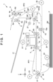
- Fig. 1 is a schematic views of a printing apparatus 1 according to this embodiment.
- a case will be described in which the present invention is applied to a serial type inkjet printing apparatus, but the present invention is also applicable to printing apparatuses of other types.
- an arrow X and an arrow Y indicate horizontal directions orthogonal to each other, and an arrow Z indicates a vertical direction.
- a downstream side and an upstream side are based on the conveyance direction of a print medium.
- printing includes not only forming significant information such as characters and graphics but also forming images, figures, patterns, and the like on print media in a broad sense, or processing print media, regardless of whether the information formed is significant or insignificant or whether the information formed is visualized so that a human can visually perceive it.
- sheet-like paper is assumed as a "print medium” serving as a print target, sheet-like cloth, a plastic film, and the like may be used as print media.
- a printing apparatus 1 is an apparatus that performs printing on sheets SH as print media stacked in a feed tray (stacker) 2, and discharges the sheets SH to a discharge tray 17.
- a main conveyance route RT1 for guiding the conveyance of the sheets SH is formed from the feed tray 2 to the discharge tray 17, and the sheets SH in the feed tray 2 are supplied one by one to the main conveyance route RT1 by a pickup roller 3.
- the pickup roller 3 is rotated by the driving force of a feed motor 22. Note that in the main conveyance route RT1 schematically shown in each drawing, there is only one route between a feed unit 4 and a conveyance unit 5, but upper and lower routes extending along upper and lower conveyance guides are shown.
- the printing apparatus 1 also includes a sub-conveyance route RT2 branched by a branch point BP from the main conveyance route RT1.
- the sub-conveyance route RT2 is a route for inverting the obverse and reverse surfaces of the sheet SH and returning the sheet SH to the main conveyance route RT1, and is used when performing double-sided printing on the sheet SH. Note that the printing apparatus 1 need not have the double-sided printing function for the sheet SH, and the sub-conveyance route RT2 and its relevant arrangement are unnecessary in this case.
- the printing apparatus 1 includes the feed unit 4 and a plurality of conveyance units 5 to 10.
- the feed unit 4 and the plurality of conveyance units 5 to 8 are arranged along the main conveyance route RT1.
- the feed unit 4, the conveyance unit 5, the conveyance unit 6, the conveyance unit 7, and the conveyance unit 8 are arranged in this order from the upstream side to the downstream side in the conveyance direction of the sheet SH in the main conveyance route RT1.
- the conveyance units 9 and 10 are arranged along the sub-conveyance route RT2, and are arranged in this order from the upstream side to the downstream side in the conveyance direction of the sheet SH in the sub-conveyance route RT2.
- the upstream side and the downstream side mean the upstream side and the downstream side in the conveyance direction of the sheet SH in the main conveyance route RT1, unless otherwise specified.
- the leading edge and trailing edge of the sheet SH mean the downstream edge and upstream edge of the sheet SH.
- the feed unit 4 feeds the sheet SH supplied to the main conveyance route RT1 by the pickup roller 3, or the sheet SH returned from the sub-conveyance route RT2 to the main conveyance route RT1, to the conveyance unit 5.
- the feed unit 4 includes a feed roller 4a, and a driven roller 4b that is urged against the feed roller 4a by a spring or the like (not shown).
- the feed roller 4a is a rotational member that rotates by the driving force of a feed motor 23, and the driven roller 4b is a rotational member that rotates following the rotation of the feed roller 4a.
- the sheet SH is nipped by a nip portion between the driving roller 4a and the driven roller 4b, and conveyed by the rotations of the driving roller 4a and the driven roller 4b.
- the pickup roller 3 is a one-way roller. Therefore, after the sheet SH is conveyed to a position exceeding the nip portion of the feed unit 4, conveyance by the feed unit 4 can be continued even when driving of the pickup roller 3 is stopped.
- this embodiment includes the pickup roller 3 and the feed roller 4a, but it is also possible to use only the feed roller 4a for feeding the sheets SH stacked in the feed tray 2.
- a sensor 31 is a sensor for detecting the passing of the leading edge and trailing edge of the sheet SH, and is an optical sensor or the like.
- the detection position of the sensor 31 is set in a position on the downstream side of the nip portion of the feed unit 4.
- the conveyance unit 5 is arranged on the upstream side of a printhead 12, and conveys the sheet SH fed by the feed unit 4 to the printhead 12.
- the conveyance unit 5 conveys the sheet SH to the downstream side between the printhead 12 and a platen 15 facing the printhead 12.
- the conveyance unit 5 includes a conveyor roller 5a, and a driven roller (pinch roller) 5b that is urged against the conveyor roller 5a by a spring or the like (not shown).
- the conveyor roller 5a is a rotational member that rotates by the driving force of a conveyor motor 24, and the driven roller 5b is a rotational member that rotates following the rotation of the conveyor roller 5a.
- the sheet SH is nipped by a nip portion between the conveyor roller 5a and the driven roller 5b, and conveyed by the rotations of the conveyor roller 5a and the driven roller 5b.
- the conveyance unit 6 is arranged on the downstream side of the printhead 12, and conveys the sheet SH conveyed by the conveyance unit 5 to the downstream side.
- the conveyance unit 6 includes a conveyor roller 6a, and a spur 6b that is urged against the conveyor roller 6a by a spring or the like (not shown).
- the conveyor roller 6a is a rotational member that rotates by the driving force of the conveyor motor 24, and the spur 6b is a rotational member that rotates following the rotation of the conveyor roller 6a.
- the conveyance units 5 and 6 share the driving source (the motor 24).
- the conveyance unit 7 is arranged on the downstream side of the printhead 12 and the conveyance unit 6, and conveys the sheet SH conveyed by the conveyance unit 6 to the downstream side.
- the conveyance unit 7 includes a conveyor roller 7a, and a driven roller 7b that is urged against the conveyor roller 7a by a spring or the like (not shown).
- the conveyor roller 7a is a rotational member that rotates by the driving force of a conveyor motor 25, and the driven roller 7b is a rotational member that rotates following the rotation of the conveyor roller 7a.
- the sheet SH is nipped by a nip portion between the conveyor roller 7a and the driven roller 7b, and conveyed by the rotations of the conveyor roller 7a and the driven roller 7b.
- the conveyance unit 8 is arranged on the downstream side of the printhead 12 and the conveyance units 6 and 7, and is a discharge unit for discharging the sheet SH conveyed by the conveyance unit 7 to the discharge tray 17.
- the conveyance unit 8 includes a conveyor roller 8a, and a driven roller 8b that is urged against the conveyor roller 8a by a spring or the like (not shown).
- the conveyor roller 8a is a rotational member that rotates by the driving force of the conveyor motor 25, and the driven roller 8b is a rotational member that rotates following the rotation of the conveyor roller 8a.
- the sheet SH is nipped by a nip portion between the conveyor roller 8a and the driven roller 8b, and conveyed by the rotations of the conveyor roller 8a and the driven roller 8b.
- the conveyance units 7 and 8 share the driving source (the motor 25).
- a flapper 16 is arranged in the branch point BP.
- the flapper 16 switches the routes to the conveyance destinations of the sheet SH between the main conveyance route RT1 and the sub-conveyance route RT2. In the position shown in Fig. 1 , the flapper 16 maintains the route to the conveyance destination of the sheet SH to the main conveyance route RT1, and the sheet SH is discharged to the discharge tray 17 via the conveyance unit 8.
- the flapper 16 is formed to be able to pivot, and switches the routes by pivoting by an actuator 27 such as an electromagnetic solenoid.
- the conveyance unit 9 is an inversion unit for conveying the sheet SH having entered the sub-conveyance route RT2 from the branch point BP.
- the sub-conveyance route RT2 has an inversion route RT21 extending upward from the branch point BP via a branch point BP', and a return route RT22 extending from the branch point BP' to the feed unit 4.
- the conveyance unit 9 is arranged in the inversion route RT21.
- the conveyance unit 9 includes a conveyor roller 9a, and a driven roller 9b that is urged against the conveyor roller 9a by a spring or the like (not shown).
- the conveyor roller 9a is a rotational member that rotates by the driving force of a conveyor motor 26, and the driven roller 9b is a rotational member that rotates following the rotation of the conveyor roller 9a.
- the sheet SH having entered the sub-conveyance route RT2 from the branch point BP moves in the inversion route RT21.
- the conveyor roller 9a is rotated in two directions, that is, a direction R1 and an opposite direction R2.
- the sheet SH is conveyed in the direction of an arrow F.
- the rotational direction of the conveyor roller 9a is switched to the direction R2.
- the sheet SH is conveyed in the opposite direction.
- the sheet SH is supplied from the branch point BP' to the return route RT22 while the obverse and reverse surfaces of the sheet SH are inverted.
- the conveyance unit 10 is an intermediate unit arranged in the return route RT22.
- the conveyance unit 10 includes a conveyor roller 10a, and a driven roller 10b that is urged against the conveyor roller 10a by a spring or the like (not shown).
- the conveyor roller 10a is a rotational member that rotates by the driving force of the conveyor motor 26, and the driven roller 10b is a rotational member that rotates following the rotation of the conveyor roller 10a.
- the sheet SH is nipped by a nip portion between the conveyor roller 10a and the driven roller 10b, and conveyed by the rotations of the conveyor roller 10a and the driven roller 10b.
- the conveyance units 9 and 10 share the driving source (the motor 26).
- the conveyor roller 10a is a one-way roller. Therefore, after the sheet SH is conveyed to a position exceeding the nip portion of the feed unit 4, conveyance by the feed unit 4 can be continued even when driving of the conveyor roller 10a is stopped.
- the printhead 12 is arranged midway along the main conveyance route RT1. In this embodiment, the printhead 12 is arranged in a position on the downstream side of the conveyance unit 5 and on the upstream side of the conveyance unit 6. The printhead 12 performs printing on the sheet SH. The sheet SH is conveyed in the X direction in the vicinity of the printhead 12. In this embodiment, the printhead 12 is an inkjet printhead that performs printing on a print medium by ejecting ink. The printhead 12 is supported by a carriage 11.
- the carriage 11 is moved back and forth by a driving unit 14 in a direction crossing the sheet SH (a direction crossing the conveyance direction of the sheet SH in the vicinity of the printhead 12).
- the carriage 11 moves back and forth in the Y direction by being guided by a guide shaft 13 extended in the Y direction.
- the driving unit 14 is a mechanism using a carriage motor 21 as a driving source, and is a transmission mechanism including a driving pulley and a driven pulley separated in the Y direction, and an endless belt wound around these pulleys.
- the carriage 11 is connected to the endless belt. When the carriage motor 21 rotates the driving pulley, the endless belt runs and the carriage 11 moves.
- the printhead 12 can also be attached to the carriage 11 so that the printhead 12 can be exchanged.
- the printing apparatus 1 of this embodiment is a serial-type printing apparatus in which the printhead 12 is mounted on the carriage 11.
- Printing control on the sheet SH is performed by alternately repeating an intermittently performed conveyance operation (intermittent conveyance operation) in which the conveyance unit 5 and/or the conveyance unit 6 conveys a print medium by a predetermined amount, and a printing operation that is performed while the conveyance by the conveyance unit 5 and/or the conveyance unit 6 is stopped.
- the printing operation is an operation of ejecting ink from the printhead 12 while moving the carriage 11 on which the printhead 12 is mounted.
- Fig. 2 is a block diagram of a control unit 40 of the printing apparatus 1.
- An MPU 41 is a processor for controlling each operation of the printing apparatus 1 and controlling data processing and the like.
- the MPU 41 controls the whole printing apparatus 1 by executing a program stored in a storage device 42.
- the storage device 42 is, for example, a ROM or a RAM.
- the storage device 42 stores the program to be executed by the MPU 41, and also stores various kinds of data necessary for processing, such as data received from a host computer 100.
- the MPU 41 controls the printhead 12 via a driver 44a.
- the MPU 41 controls the carriage motor 21 via a driver 44b.
- the MPU 41 also controls the feed motors 22 and 23, the conveyor motors 24 to 26, and the actuator 27 via drivers 44c to 44i.
- a sensor group 30 includes the sensor 31, a sensor (not shown) for detecting the position of the carriage 11 in the Y direction, and sensors (not shown) for detecting the rotation amounts of the feed motors 22 and 23 and the conveyor motors 24 to 26. By detecting the rotation amount of each motor, it is possible to specify the rotation amount of a corresponding feed roller or conveyor roller, and calculate the conveyance amount of the sheet SH.
- the host computer 100 is, for example, a personal computer or a portable terminal (for example, a smartphone or a tablet terminal) that is used by the user.
- a printer driver 100a for performing communication between the host computer 100 and the printing apparatus 1 is installed in the host computer 100.
- the printing apparatus 1 includes an I/F (interface) unit 43, and the communication between the host computer 100 and the MPU 41 is executed via the I/F unit 43.
- the printer driver 100a In a case where, for example, the user inputs execution of printing control to the host computer 100, the printer driver 100a generates a print job by gathering data of an image to be printed, and the printing conditions (various pieces of information such as the quality of a printed image), and transmits the print job to the printing apparatus 1.
- control to be executed by the MPU 41 will be explained below.
- the MPU 41 processes the print job and expands the processed data on the storage device 42.
- the MPU 41 starts the control based on the expanded data.
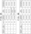
- Figs. 3A and 3B show examples of printing conditions related to the conveyance operation of the sheet SH, among printing conditions contained in the print job.
- the printing apparatus 1 of this embodiment can perform both single-sided printing and double-sided printing.
- Fig. 3A shows an example of printing conditions when performing double-sided printing on two sheets SH
- Fig. 3B shows an example of printing conditions when performing single-sided printing on three sheets SH. Note that as a printing order, a facedown method in which an immediately preceding printing surface in a facedown state is discharged to the discharge tray 17 is assumed, but a faceup method is also usable.
- Printing Order N indicates the number of times and the order of printing control for one surface of the sheet SH, and N is a variable. Printing control is executed for four surfaces (four times) in the example shown in Fig. 3A , and three surfaces (three times) in the example shown in Fig. 3B .
- Page Number K indicates a page of the final printed product to which the printing order N corresponds, and K is a variable.
- Sheet M indicates a target sheet SH of the printing order N, and M is a variable. In this embodiment, a number is given in the order of feed from the feed tray 2.
- a sheet SH1 indicates the sheet SH fed first from the feed tray 2 in the print job
- a sheet SH2 indicates the sheet SH fed second from the feed tray 2
- a sheet SH3 indicates the sheet SH fed third from the feed tray 2.
- the variable M is sometimes represented as M(N) as a function of the printing order N.
- M(1) means the sheet SH1
- M(2) means the sheet SH2
- M(3) means the sheet SH1.
- M(3) means the sheet SH3.
- Print Surface F indicates which one of the obverse and reverse surfaces (in other words, the first and second surfaces) of the sheet SH is a printing target surface, and is sometimes represented as F(N) as a function of the printing order N.
- F(1) means that the reverse surface of the sheet SH1 is a printing target surface
- F(3) means that the obverse surface of the sheet SH1 is a printing target surface.
- Fee Source Q indicates which of the feed tray 2 or the sub-conveyance route RT2 is the feed source of the sheet SH, and is sometimes represented as Q(N) as a function of the printing order N.
- the sheet SH is inverted in the inversion route RT21 of the sub-conveyance route RT2, and returned to the feed unit 4 via the return route RT22.
- the feed tray 2 or the sub-conveyance route RT2 is the feed source.
- the feed tray 2 is always the feed source.
- Post-Printing Processing G indicates whether the processing of the printing sheet SH is discharge to the discharge tray 17 or inversion in the sub-conveyance route RT2, and is sometimes represented as G(N) as a function of the printing order N.
- the processing G In single-sided printing, the processing G is always discharge. In double-sided printing, the processing G is inversion after the first surface is printed, and is discharge after the second surface is printed.
- the flapper 16 is moved beforehand so as to guide the sheet SH to the sub-conveyance route RT2.
- the feed motor 22 is driven at low speed. Consequently, the pickup roller 3 is rotated at, for example, 7.6 inches/sec (the conveyance velocity of the sheet SH, and the same expression has the same meaning hereinafter).
- the pickup roller 3 rotates, the uppermost one of the sheets SH stacked in the feed tray 2 is picked up. This sheet is represented as a sheet SH1.
- the sheet SH1 picked up by the pickup roller 3 is conveyed in the main conveyance route RT1 by the feed roller 4a rotating in the same direction as the pickup roller 3.
- the feed motor 23 drives the feed roller 4a at the same speed as the pickup roller 3.
- the pickup roller 3 conveys the sheet SH1 to a position exceeding the feed roller 4a, and stops so as not to pick up the next sheet SH.
- the pickup roller 3 is a one-way roller, so the feed roller 4a can continue feeding even when the pickup roller 3 stops.
- the feed motor 23 When the sensor 31 installed on the downstream side in the conveyance direction of the feed roller 4a detects the leading edge of the sheet SH1, the feed motor 23 is switched to high-speed driving.
- the feed roller 4a rotates at, for example, 20 inches/sec.
- the conveyor motor 24 is driven, so the conveyor roller 5a starts rotating.
- the conveyor roller 5a conveys the sheet SH1 at, for example, 15 inches/sec.
- the leading edge of the sheet SH1 is abutted against the nip portion of the conveyance unit 5
- the leading edge of the sheet SH1 is positioned once in the position of the conveyor roller 5a. Based on this position, the positions of the leading edge and trailing edge of the sheet SH1 can be calculated by the rotation amount of the conveyor roller 5a after that. This position control conveys the sheet SH1 to the position facing the printhead 12 in alignment as well.
- the printing apparatus 1 of this embodiment is a serial-type printing apparatus in which the printhead 12 is mounted on the carriage 11.
- Printing on the sheet SH1 is performed by repeating a conveyance operation in which the conveyor roller 5a intermittently conveys a print medium by a predetermined amount each time, and a printing operation in which the printhead 12 ejects ink while the carriage 11 is moved.
- the feed motor 23 is switched to low-speed driving. That is, the feed roller 4a rotates at, for example, 7.6 inches/sec.
- the feed motor 23 While the conveyor roller 5a is intermittently conveying the sheet SH1 by the predetermined amount each time, the feed motor 23 also intermittently drives the feed roller 4a.
- the feed roller 4a rotates when the conveyor roller 5a rotates, and the feed roller 4a is standing still when the conveyor roller 5a is standing still.
- the rotational speed of the feed roller 4a is lower than that of the conveyor roller 5a. Accordingly, the sheet SH is pulled tight between the conveyor roller 5a and the feed roller 4a. Also, the feed roller 4a is co-rotated by the conveyor roller 5a via the sheet SH1.
- Fig. 5B shows a state in which the leading edge of the sheet SH1 has passed the conveyor roller 6a.
- the sensor 31 requires a predetermined interval between successive sheets SH due to a cause such as the responsiveness of the sensor. Accordingly, the pickup operation of the sheet SH2 is started after the trailing edge of the sheet SH1 is detected by the sensor 16 and it is determined that the sheet SH1 has passed the sensor 16. Also, when feeding the sheet SH2, the rotation of the pickup roller 3 is so controlled that the interval between the trailing edge of the sheet SH1 and the leading edge of the sheet SH2 is a predetermined distance or more.
- the positions of the leading edge and trailing edge of the sheet SH are specified by calculations based on the rotation amounts of the various rollers. However, these positions can also be calculated by installing another sensor.
- the trailing edge of the sheet SH1 has passed the feed roller 4a and is slightly hanging down.
- the sheet SH2 picked up by the pickup roller 3 is conveyed by the feed roller 4a.
- printing control is executed in parallel on the sheet SH1.
- the feed motor 23 is switched to high-speed driving. That is, the feed roller 4a rotates at, for example, 20 inches/sec.
- the conveyor motors 25 and 26 intermittently drive the conveyor rollers 7a and 9a in the same direction and at the same speed as those of the conveyor roller 5a.
- overlap state formation control can be executed.
- the sheet SH2 is fed at a speed higher than the conveyance velocity of the sheet SH1, thereby forming an overlap state in which the leading edge of the sheet SH2 overlaps the trailing edge of the sheet SH1 before the conveyor roller 5a. Since printing control is performed on the sheet SH1 based on the print data, the conveyor roller 5a intermittently conveys the sheet SH1. On the other hand, after the trailing edge of the sheet SH2 is detected by the sensor 31, the sheet SH2 can catch up with the sheet SH1 by continuously rotating the feed roller 4a at 20 inches/sec. After that, the sheet SH2 is conveyed until the leading edge arrives at a predetermined position slightly before the nip portion of the conveyance unit 5.
- the position of the leading edge of the sheet SH2 is calculated from the rotation amount of the feed roller 4a since the leading edge of the sheet SH2 is detected by the sensor 31, and is controlled based on this calculation result.
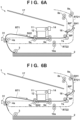
- the sheet SH1 has entered the sub-conveyance route RT2 by being guided by the flapper 16.
- a skew correcting operation is performed on the sheet SH2. While the conveyor roller 5a is standing still in order to perform the printing operation on the sheet SH1, the leading edge of the sheet SH2 is abutted against the nip portion by driving the feed roller 4a.
- the skew correcting operation for the sheet SH2 is performed while the conveyor roller 5a is standing still for the printing operation for the last line of the sheet SH1, in order to minimize the influence on the printing quality of the sheet SH1.
- the sheet SH2 can be aligned while maintaining the state in which the sheet SH2 overlaps the sheet SH1 by rotating the conveyor roller 5a by a predetermined amount. Note that the overlap portion of the sheets SH1 and SH2 is conveyed as it is nipped by the nip portion of the conveyance unit 5.
- overlap amount reduction control can be executed.
- a paper jam may occur.
- the sheet SH2 may interfere with the sheet SH1 and cause a paper jam depending on the vertical relationship between the sheets SH1 and SH2.
- An example is a case in which while the sheet SH1 passes the branch point BP along the main conveyance route RT1, the succeeding sheet SH2 overlapping the sheet SH1 is conveyed to the sub-conveyance route RT2.
- reduction control for reducing the overlap amount is performed before the overlap portion arrives at the branch point BP (in other words, before the sheet SH2 arrives at the branch point BP).
- the overlap amount is reduced to 0.
- a predetermined effect can be obtained if the overlap amount can be reduced.
- the conveyor motor 25 continuously rotates the conveyor roller 7a independently of the conveyor rollers 5a and 6a. Note that the conveyor roller 9a is rotated by the conveyor roller 26 at the same speed as that of the conveyor roller 7a in the R1 direction (see Fig. 1 )
- the trailing edge of the sheet SH1 can be separated from the sheet SH2 by the relative speed difference between the sheets SH1 and SH2.
- the speed of the conveyor roller 7a is controlled such that the reduction control can be completed before the trailing edge of the preceding sheet SH1 passes the conveyor roller 7a. Note that an example of this speed control will be described later.
- the reduction control as described above can prevent the overlap portion of the sheets SH1 and SH2 from passing the branch point BP, thereby preventing the occurrence of a paper jam. Since the reduction control is executed during the printing control on the sheet SH2, the reduction control includes at least a control zone in which the conveyor rollers 5a and 6a stop conveying the succeeding sheet SH2 and the conveyor roller 7a conveys the preceding sheet SH1.
- the conveyance of the sheet SH2 is stopped during its printing operation.
- the speed of the conveyor roller 7a need not be higher than that of the conveyor roller 5a in order to reduce the overlap amount.
- the overlap amount of the sheets SH1 and SH2 can be reduced at a lower conveyance velocity of the sheet SH1. In other words, when the reduction control is performed during the printing operation, it is possible to reduce the conveyance velocity and suppress deterioration of the noise and electric power, compared to a case in which no reduction control is performed during the printing operation.
- the reduction control can be performed during the conveyance operation of the sheet SH2 as well.
- the overlap amount can effectively be reduced because the speed of the conveyor roller 7a is higher than that of the conveyor roller 5a. It is, of course, needless to say that the reduction control can also be performed even when it is completed during the printing operation of the sheet SH2.
- the conveyor roller 9a continuously conveys the sheet SH1 to a position where the trailing edge of the sheet SH1 passes the branch point BP'.
- the conveyor motor 26 is reversed to the direction R2 (see Fig. 1 ), thereby switching driving to high-speed driving. In this conveyance direction, the leading edge and trailing edge of the sheet SH1 are switched.
- the conveyor rollers 9a and 10a are rotated at, for example, 18 inches/sec.
- the sheet SH1 enters the return route RT22 and is conveyed to the feed roller 4a as shown in Fig. 8B .
- the conveyor motor 26 and the feed motor 23 are driven at low speed. Consequently, the conveyor roller 10a and the feed roller 4a are rotated at, for example, 7.6 inches/sec. Then, the conveyor roller 10a and the feed roller 4a convey the sheet SH1 from the return route RT22 to the main conveyance route RT1.
- overlap state formation control is performed.
- the sheet SH2 is the preceding sheet and the sheet SH1 is the succeeding sheet, unlike in the case shown in Fig. 6A .
- Printing control is performed on the sheet SH2 based on the print data.
- the sensor 31 detects the trailing edge of the sheet SH2
- the conveyor motor 26 and the feed motor 23 are switched to high-speed driving. That is, the conveyor roller 10a and the feed roller 4a rotate at, for example, 20 inches/sec.
- An overlap state in which the leading edge of the sheet SH1 overlaps the trailing edge of the sheet SH2 is formed by rapidly moving the sheet SH1.
- the conveyor roller 5a intermittently conveys the sheet SH2.
- the sheet SH1 can catch up with the sheet SH2 by continuously rotating the feed roller 4a at 20 inches/sec. After that, the sheet SH1 is conveyed until its leading edge arrives at a predetermined position slightly before the nip portion of the conveyance unit 5.
- the position of the leading edge of the sheet SH1 is calculated from the rotation amount of the feed roller 4a since the sensor 31 detects the leading edge of the sheet SH1, and controlled based on the calculation result.
- the sheet SH2 enters the sub-conveyance route RT2 by being guided by the flapper 16.
- a skew correcting operation of the sheet SH1 is performed.
- the conveyor roller 5a is standing still in order to perform the printing operation on the sheet SH2
- the leading edge of the sheet SH1 is abutted against the nip portion by driving the feed roller 4a.
- the skew correcting operation of the sheet SH1 is performed when the conveyor roller 5a is standing still in order to perform the operation of printing the last line on the sheet SH2, in order to minimize the influence on the printing quality of the sheet SH2.
- the sheet SH1 can be aligned while maintaining the state in which the sheet SH1 overlaps the sheet SH2 by rotating the conveyor roller 5a by a predetermined amount. Note that the overlap portion of the sheets SH1 and SH2 is conveyed as it is nipped by the nip portion of the conveyance unit 5.
- the feed motor 23 is switched to low-speed driving. That is, the feed roller 4a rotates at, for example, 7.6 inches/sec.
- the conveyor roller 5a intermittently conveys the sheet SH2 by a predetermined amount each time, the conveyor motor 23 also intermittently drives the feed roller 4a.
- An operation of printing the print data of the first page on the obverse surface (upper surface) of the sheet SH1 is started by ejecting ink from the printhead 12 based on the print data.
- the sheet SH2 is also intermittently conveyed.
- whether the trailing edge of the sheet SH2 has passed the conveyor roller 6a is determined from the rotation amount of the conveyor roller 5a since the start of the alignment operation on the sheet SH2, and from the length of the sheet SH2.
- the conveyor roller 7a can convey the preceding sheet SH2, and the conveyor rollers 5a and 6a can convey the succeeding sheet SH1.
- the conveyor rollers 5a and 6a have no influence on the conveyance of the sheet SH2, and the conveyor roller 7a has no influence on the conveyance of the sheet SH1. Reduction control is started at this timing.
- the conveyor motor 25 continuously rotates the conveyor roller 7a independently of the conveyor rollers 5a and 6a.
- the conveyor motor 26 rotates the conveyor roller 9a as well in the direction R1 (see Fig. 1 ) at the same speed as that of the conveyor roller 7a.
- the trailing edge of the sheet SH2 can be separated from the sheet SH1 by the relative speed difference between the sheets SH1 and SH2.
- the speed of the conveyor roller 7a is controlled so that the reduction control can be completed before the trailing edge of the preceding sheet SH2 passes the conveyor roller 7a. Note that an example of this speed control will be described later.
- the reduction control Since the reduction control is executed during the printing control of the sheet SH1, the reduction control includes at least a control zone in which the conveyance of the succeeding sheet SH1 by the conveyor rollers 5a and 6a is stopped and the conveyor roller 7a conveys the preceding sheet SH2.
- the conveyance of the sheet SH1 is stopped during its printing operation.
- the sheet SH2 By continuously conveying the sheet SH2 during this printing operation, it is possible to maximize the relative speed difference between the sheets SH2 and SH1, and efficiently reduce the overlap amount.
- the overlap amount of the sheets SH2 and SH1 can be reduced at a lower conveyance velocity of the sheet SH2. If the reduction control is not completed during the printing operation of the sheet SH2, the reduction control is performed during the conveyance operation of the sheet SH2. In this case, the overlap amount can effectively be reduced because the speed of the conveyor roller 7a is higher than that of the conveyor roller 5a.
- the conveyor roller 9a continuously conveys the sheet SH2 to a position where its trailing edge passes the branch point BP'.
- the flapper 16 is pivoted in accordance with a post-printing process of the sheet SH1 that passes the flapper 16 next. Since the post-printing process of the sheet SH1 is discharge, the flapper 16 moves to a position where the conveyance route of the sheet SH1 is maintained in the main conveyance route RT1. Whether the trailing edge of the sheet SH2 has passed the flapper 16 can be determined from the rotation amounts of the various rollers or by installing another sensor.
- the conveyor motor 26 is reversed to the direction R2 (see Fig. 1 ), and driving is switched to high-speed driving.
- the leading edge and trailing edge of the sheet SH2 are switched in this conveyance direction.
- the conveyor rollers 9a and 10a are rotated at, for example, 18 inches/sec.
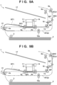
- the sheet SH2 enters the return route RT22, and is conveyed to the feed roller 4a as shown in Fig. 11B .
- the conveyor motor 26 and the feed motor 23 are driven at low speed. Consequently, the conveyor roller 10a and the feed roller 4a are rotated at, for example, 7.6 inches/sec. Then, the conveyor roller 10a and the feed roller 4a convey the sheet SH2 from the return route RT22 to the main conveyance route RT1.
- overlap state formation control is performed.
- the sheet SH1 is the preceding sheet and the sheet SH2 is the succeeding sheet again.
- Printing control is performed on the sheet SH1 based on the print data.
- the sensor 31 detects the trailing edge of the sheet SH1
- the conveyor motor 26 and the feed motor 23 are switched to high-speed driving. That is, the conveyor roller 10a and the feed roller 4a rotate at, for example, 20 inches/sec.
- An overlap state in which the leading edge of the sheet SH2 overlaps the trailing edge of the sheet SH1 is formed by rapidly moving the sheet SH2. Since the printing control is performed on the sheet SH1 based on the print data, the conveyor roller 5a intermittently conveys the sheet SH1.
- the sheet SH2 can catch up with the sheet SH1 by continuously rotating the feed roller 4a at 20 inches/sec. After that, the sheet SH2 is conveyed until its leading edge arrives at a predetermined position slightly before the nip portion of the conveyance unit 5. The position of the leading edge of the sheet SH2 is calculated from the rotation amount of the feed roller 4a since the sensor 31 detects the leading edge of the sheet SH2, and is controlled based on the calculation result. The leading edge of the sheet SH1 passes the branch point BP and moves toward the conveyor roller 8a.
- a skew correcting operation of the sheet SH2 is performed. While the conveyor roller 5a is standing still in order to perform the printing operation on the sheet SH1, the leading edge of the sheet SH2 is abutted against the nip portion by driving the feed roller 4a.
- the skew correcting operation of the sheet SH2 is performed while the conveyor roller 5a is standing still for an operation of printing the last line on the sheet SH1, in order to minimize the influence on the printing quality of the sheet SH1.
- the sheet SH2 can be aligned while maintaining the state in which the sheet SH2 overlaps the sheet SH1 by rotating the conveyor roller 5a by a predetermined amount. Note that the overlap portion of the sheets SH1 and SH2 is conveyed as it is nipped by the nip portion of the conveyance unit 5.
- the feed motor 23 When the sheet SH2 is aligned, the feed motor 23 is switched to low-speed driving. That is, the feed roller 4a rotates at, for example, 7.6 inches/sec.
- the feed motor 23 also intermittently drives the feed roller 4a.
- An operation of printing the print data of the third page on the obverse surface (upper surface) of the sheet SH2 is started by ejecting ink from the printhead 12 based on the print data.
- the sheet SH2 is intermittently conveyed for this printing operation, the sheet SH1 is also intermittently conveyed.
- overlap amount reduction control is performed. If the sheets SH1 and SH2 are discharged as they are largely overlapping each other, the stacking order of the sheets SH1 and SH2 on the discharge tray 25 may be inverted. Therefore, overlap amount reduction control is performed. In this embodiment, the overlap amount is reduced to 0. However, even when the overlap amount is not reduced to 0, a predetermined effect is obtained if the overlap amount can be reduced.
- whether the trailing edge of the sheet SH1 has passed the conveyor roller 6a is determined from the rotation amount of the conveyor roller 5a since the start of the alignment operation on the sheet SH1, and from the length of the sheet SH1.
- the conveyor roller 7a can convey the preceding sheet SH1, and the conveyor rollers 5a and 6a can convey the succeeding sheet SH2.
- the conveyor rollers 5a and 6a have no influence on the conveyance of the sheet SH1, and the conveyor roller 7a has no influence on the conveyance of the sheet SH2. Reduction control is started at this timing.
- the conveyor motor 25 continuously rotates the conveyor roller 7a independently of the conveyor rollers 5a and 6a.
- the conveyor roller 8a sharing the conveyor motor 25 also continuously rotates.
- the trailing edge of the sheet SH1 can be separated from the sheet SH2 by the relative speed difference between the sheets SH1 and SH2.
- the speed of the conveyor roller 7a is controlled so that the reduction control can be completed before the trailing edge of the preceding sheet SH1 passes the conveyor roller 7a. Note that an example of this speed control will be described later.
- the reduction control as described above can prevent the phenomenon that the sheets SH1 and SH2 are discharged as they are overlapping each other and as a consequence the stacking order of the sheets SH1 and SH2 on the discharge tray 17 is inverted. Since the reduction control is executed during printing control of the sheet SH2, the reduction control includes at least a control zone in which the conveyance of the succeeding sheet SH2 by the conveyor rollers 5a and 6a is stopped and the conveyor roller 7a conveys the preceding sheet SH1.
- the conveyance of the sheet SH2 is stopped during its printing operation.
- the speed of the conveyor roller 7a need not be higher than that of the conveyor roller 5a in order to reduce the overlap amount.
- the overlap amount of the sheets SH1 and SH2 can be reduced at a lower conveyance velocity of the sheet SH1. In other words, when the reduction control is performed during the printing operation, it is possible to reduce the conveyance velocity and suppress deterioration of the noise and electric power, compared to a case in which no reduction control is performed during the printing operation.
- the reduction control is not completed during the printing operation of the sheet SH2, the reduction control is performed during the conveyance operation of the sheet SH2 as well.
- the overlap amount can effectively be reduced because the speed of the conveyor roller 7a is higher than that of the conveyor roller 5a.
- the sheet SH1 is discharged to the discharge tray 17 because printing on the two surfaces is complete.
- double-sided printing of the sheet SH2 as the last sheet of this job is also completed.
- the sheet SH2 is discharged to the discharge tray 17 as shown in Fig. 14B by rotating the conveyor rollers 8a, 7a, 6a, and 5a in the same direction.
- step S1 the printing order N is initialized to 1.
- step S2 a maximum printing order Nmax is acquired from the printing conditions.
- Nmax is a maximum value of the printing order N, and is 4 in the example shown in Fig. 3A and 3 in the example shown in Fig. 3B .
- Processing G(1) after printing is inversion in the example shown in Fig. 3A , so the flapper 16 is moved to the position shown in Fig. 4B .
- Processing G(1) after printing is discharge in the example shown in Fig. 3B , so the flapper 16 is moved to the position shown in Fig. 1 .
- step S4 feeding of an M(N)th sheet SH from a feed source Q(N) is started. If the feed source Q(N) is the feed tray 2, the feed motor 22 is initially driven at low speed. Consequently, the pickup roller 3 is rotated at, for example, 7.6 inches/sec. When the pickup roller 3 rotates, the uppermost one of the sheets SH stacked in the feed tray 2 is picked up. The sheet SH picked up by the pickup roller 3 is conveyed by the feed roller 4a rotating in the same direction as the pickup roller 3. The feed motor 23 drives the feed roller 4a at the same speed as that of the pickup roller 3.
- the pickup roller 3 rotates by a predetermined amount with which the sheet SH can be conveyed to a position exceeding the feed roller 4a, and then stops so as not to pick up the next conveyance medium.
- the pickup roller 3 is a one-way roller, so the conveyance by the feed roller 4a can be continued even when the pickup roller 3 is stopped.
- the conveyor motor 26 is driven at low speed, and the feed motor 23 is also driven at low speed. Consequently, the conveyor roller 10a and the feed roller 4a are rotated at, for example, 7.6 inches/sec. Then, the conveyor roller 10a and the feed roller 4a convey the sheet SH in the direction of the conveyor roller 5a through the return route RT22 and the main conveyance route RT1.
- step S5 whether the sensor 31 has detected the leading edge of the M(N)th sheet SH (whether the leading edge has passed the sensor 31) is determined. If it is determined that the leading edge has passed, step S6 is executed. In step S6, the feed speed of the M(N)th sheet SH is switched to a high speed (for example, 20 inches/sec). Since the feed motor 23 is switched to high-speed driving, the feed roller 4a rotates at 20 inches/sec. If a preceding M(N - 1)th sheet SH exists, an operation of allowing the succeeding sheet SH to catch up with the preceding sheet SH is started.
- a high speed for example, 20 inches/sec
- Fig. 16 is a flowchart of the overlap state formation control.
- step S21 the conveyance of the sheet SH is stopped so that the leading edge of the M(N)th sheet SH is positioned in a predetermined position before the conveyor roller 5a.
- step S21 the conveyance of the sheet SH is stopped so that the leading edge of the M(N)th sheet SH is positioned in a predetermined position before the conveyor roller 5a.
- step S21 the conveyance of the sheet SH is stopped so that the leading edge of the M(N)th sheet SH is positioned in a predetermined position before the conveyor roller 5a.
- an overlap state in which the leading edge of the succeeding sheet SH overlaps the trailing edge of the preceding sheet SH is formed.
- the position of the leading edge of the M(N)th sheet SH is calculated from the rotation amount of the feed roller 4a since the leading edge of the M(N)th sheet SH is detected by the sensor 31, and is controlled based on the calculation result.
- step S22 whether a predetermined overlap execution condition is met is determined.
- the overlap execution condition is the determination of whether it is possible to overlap the trailing edge of the preceding sheet SH and the leading edge of the succeeding sheet SH and convey them. For example, the determination is NO if the preceding sheet SH has already passed the conveyor roller 5a. The determination is NO if the overlap amount is smaller than the predetermined amount. Also, if, for example, the overlap amount is larger than the conveyance distance between the conveyor rollers 6a and 7a, the determination is NO because it becomes difficult to separate the sheets in reduction control (to be described later). Furthermore, if, for example, the reduction control (to be described later) is executed by setting a target distance as the separation distance between the sheets, and if the overlap amount exceeds this target separation distance, the determination is NO.
- step S23 is executed.
- step S23 it is determined whether an operation of printing the last line of the M(N - 1)th preceding sheet SH is started. If it is determined that the operation is not started (step S23: NO), the process waits for the start of the printing operation. If it is determined that the operation is started (step S23: YES), the processing (skew correction) in step S9 of Fig. 15 is executed.
- step S24 a process of pausing the conveyance of the M(N)th succeeding sheet SH until the M(N - 1)th preceding sheet SH passes the conveyor roller 5a. After that, the processing (skew correction) in step S9 of Fig. 15 is executed.
- step S10 alignment of the M(N)th sheet SH is performed.
- Alignment of the M(N)th sheet SH can be performed by rotating the conveyor roller 5a by a predetermined amount. In this case, if skew correction is performed on the M(N)th sheet SH in step S9 by overlapping this sheet on the M(N - 1)th sheet SH, alignment is performed by maintaining the overlap state.
- step S11 the feed speed of the M(N)th sheet SH is switched to low speed (for example, 7.6 inches/sec).
- low speed for example, 7.6 inches/sec.
- step S12 an operation of printing the data of a page having a page number K(N) is started on a printing surface F(N) of the M(N)th sheet SH.
- the feed motor 23 also intermittently drives the feed roller 4a.
- the M(N)th sheet SH is intermittently conveyed for the printing operation
- the M(N -1)th sheet SH is also intermittently conveyed.
- step S16 inversion/discharge control is executed.
- Fig. 20 is a flowchart showing a processing example.
- step S41 whether processing G(N - 1) after printing is inversion is determined. If it is determined that the processing is inversion, step S42 is executed, that is, the M(N - 1)th sheet SH is conveyed to the sub-conveyance route RT2 by rotating the conveyor roller 7a. In this step, the position of the flapper 16 is already moved by another processing to a position for guiding the sheet SH to the sub-conveyance route RT2.
- step S43 whether the trailing edge of the M(N - 1)th sheet SH has passed the flapper 16 is determined. This determination on whether the trailing edge has passed the flapper 16 can be performed from the rotation amounts of the various rollers, and can also be performed by installing another sensor. If it is determined that the trailing edge has passed the flapper 16, step S44 is executed. In step S44, the flapper 16 is so moved as to correspond to processing G(N) after printing is performed on the succeeding sheet SH.
- step S45 whether the trailing edge of the M(N - 1)th sheet SH has passed the branch point BP' is determined. If it is determined that the trailing edge has passed, step S46 is executed. In step S46, the M(N - 1)th sheet SH is conveyed to the return route RT22. By switching the conveyor motor 26 to high-speed driving for reverse rotation (the direction R2 in Fig. 1 ), the conveyor rollers 9a and 10a are rotated at, for example, 18 inches/sec. When the conveyance directions are thus switched, the leading edge and trailing edge of the M(N - 1)th sheet SH are switched.
- step S47 the M(N - 1)th sheet SH is stopped when the leading edge of the sheet SH arrives at a predetermined position before the main conveyance route RT1.
- the position in this step is also calculated from the rotation amount of each roller since the start of alignment, and from the length of the sheet.
- step S17 in Fig. 15 is executed.
- step S48 is executed, that is, the M(N - 1)th sheet SH is discharged to the discharge tray 17 by rotating the conveyor rollers 8a and 7a.
- step S49 whether the trailing edge of the M(N - 1)th sheet SH has passed the flapper 16 is determined. If it is determined that the trailing edge has passed the flapper 16, step S50 is executed. In step S50, the flapper 16 is so moved as to correspond to processing G(N) after printing is performed on the succeeding sheet SH.
- step S18 whether the printing order N after the addition is equal to or larger than the maximum printing order Nmax is determined. If it is determined that the printing order N is equal to or smaller than the maximum printing order Nmax, step S19 is executed. In step S19, whether the trailing edge of the M(N - 1)th sheet SH has passed the sensor 31 is determined. If it is determined that the trailing edge has passed the sensor 31, the process returns to step S4 to start the feed operation, and control is executed by the same flow as described above.
- step S20 the M(N - 1)th sheet SH is discharged.
- the sheet SH can be discharged to the discharge tray 17 by rotating the conveyor rollers 8a, 7a, 6a, and 5a in the same direction. The process is completed as described above.
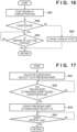
- Fig. 17 is a flowchart showing a processing example of the reduction control in step S15.
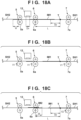
- Figs. 18A to 19C are views for explaining the reduction control.
- the reduction control uses at least two conveyance units.
- This embodiment uses the conveyance units 6 and 7.
- the conveyance unit 6 is positioned on the upstream side of the conveyance unit 7 in the conveyance direction of the sheet SH. A case in which the overlap amount of the preceding sheet SH1 and the succeeding sheet SH2 is reduced will be explained below.
- Fig. 18A shows a state in which skew correction of the succeeding sheet SH2 is performed. While the conveyor roller 5a is standing still in order to perform an operation of printing the last line of the sheet SH1, the skew correcting operation of the sheet SH2 is performed by abutting the leading edge of the sheet SH2 against the nip portion of the conveyance unit 5. In this state, the trailing edge of the sheet SH1 and the leading edge of the sheet SH2 overlap each other by an overlap amount W in the conveyance direction.
- the reduction control is based on the assumption that the overlap amount W is smaller than the distance between the conveyor rollers 6a and 7a.
- Dn is the distance of the nozzle region of the printhead 12, and is the distance from the most upstream side to the most downstream side of ejection nozzles of the printhead 12, that is, a maximum printing width in the conveyance direction. Accordingly, letting Ds be the printing width in one printing operation, Ds ⁇ Dn holds. The printing width Ds can change from one printing operation to another.
- IM1 indicates an image printed on the sheet SH1.
- the sheet SH2 can be aligned while maintaining a state in which the sheet SH2 overlaps the sheet SH1 by the overlap amount W by rotating the conveyor roller 5a by a predetermined amount.
- Fig. 18B shows a state in which this alignment is performed, that is, the most downstream end of a prospective printing region of the sheet SH2 matches the position of an ejection nozzle on the most downstream side of the ejection nozzles of the printhead 12.
- V1 indicates the velocity during intermittent conveyance of the sheets SH1 and SH2.
- the reduction control is started after the trailing edge of the preceding sheet SH1 has passed the conveyor roller 6a on the upstream side to be used in the reduction control. Note that the start timing is not limited to “immediately after passage” and need only be “after passage”. IM2 indicates an image printed on the sheet SH2.
- the reduction control is so executed as to be terminated before the trailing edge of the preceding sheet SH1 passes a given position T.
- the position T is set before the conveyor roller 7a.
- the position T can also be matched with the conveyor roller 7a.
- the reduction control is so executed as to be terminated before the trailing edge of the preceding sheet SH1 passes the conveyor roller 7a.
- the reduction control is so executed as to be terminated before the leading edge of the succeeding sheet SH2 arrives at the conveyor roller 7a.
- the region from the conveyor roller 6a to the position T is a separation region, and the length of the region is L.
- Dp is the interval between the trailing edge of the preceding sheet SH1 and the leading edge of the succeeding sheet SH2 after the reduction control.
- the distance of (L - W - Dp) is a scan determination distance, and is referred to by calculating a scan count S when performing printing on the succeeding sheet SH2.
- the scan count can also be regarded as the number of times of movement of the carriage 11.
- step S31 a conveyance velocity V2 of the preceding sheet SH1 is calculated.
- the MPU 41 acquires the overlap amount W.
- the scan count S when the leading edge of the succeeding sheet SH2 advances the scan determination distance (L - W - Dp) is calculated from print data to be printed on the succeeding sheet SH2.
- a separation time Tmax is calculated.
- Tmax (L - W - Dp)/V1 + S•Ts can be calculated from the overlap amount W, the scan count S, a one-scan required time Ts, the length L of the separation region, the sheet interval Dp after reduction control, and the conveyance velocity V1 of the succeeding sheet SH2.
- the conveyance velocity V1 of the succeeding sheet SH2 is the conveyance velocity of the conveyor roller 6a.
- the one-scan required time Ts is a t2-t3 time or a t4-t5 time shown in Fig. 19C .
- the t4-t5 time includes the waiting times before and after printing. If the required time Ts changes from one printing operation to another, the average value of the different times can be used.
- step S32 whether the trailing edge of the preceding sheet SH1 has passed the conveyor roller 6a is determined. In this embodiment, whether the trailing edge has passed the conveyor roller 6a is determined. If it is determined that the trailing edge has passed the conveyor roller 6a, the process advances to step S33.
- step S33 the conveyance roller 7a to be used in separation on the downstream side in the conveyance direction is rotated at a velocity higher than V2.
- Fig. 18C shows a state in which the conveyor roller 7a starts rotating at a velocity higher than V2.
- the preceding sheet SH1 is separated from the succeeding sheet SH2, so the overlap amount W reduces to W'.
- the conveyor rollers 5a and 6a are standing still in Fig. 18C , and are rotating at the velocity V1 in Fig. 19A .
- a sheet interval larger than the interval Dp can be obtained until the trailing edge of the sheet SH1 passes the position T, so the overlap state can be canceled.
- step S34 whether the interval between the trailing edge of the preceding sheet SH1 and the leading edge of the succeeding sheet SH2 is equal to or larger than Dp is determined. If it is determined that the interval is equal to or larger than Dp, the reduction control is terminated.
- Fig. 19C shows changes in the printing operation and conveyance velocity of the succeeding sheet SH2 and the conveyance velocity of the preceding sheet SH1 after the reduction control is started.
- the reduction control is started at time t1, and the preceding sheet SH1 is conveyed at the velocity V2 (> V1) by continuous rotation of the conveyor roller 7a. Intermittent conveyance is performed on the succeeding sheet SH2, so the conveyance stops while the printing operation is executed.
- the relative velocity difference between the preceding sheet SH1 and the succeeding sheet SH2 is maximized during the time t2-t3 or the time t4-t5, so the reduction of the overlap amount is accelerated.
- the overlap amount of the preceding sheet SH1 and the succeeding sheet SH2 can be reduced at a lower conveyance velocity of the preceding sheet SH1.
- there is no influence such as a delay of the printing control on the succeeding sheet SH2 during the reduction control.
- the interval Dp is Dp ⁇ 0 in this embodiment, and the overlap state can be canceled by Dp ⁇ 0.
- the interval Dp can also be Dp ⁇ 0. In this case, the overlap state is not completely canceled, but the overlap amount can be reduced.
- Dp can also be set by experimentally obtaining an overlap amount with which no paper jam occurs at the branch point BP, or an overlap amount with which the stacking order of a plurality of sheets SH does not change on the discharge tray 17.
- V2 can be reduced. It is also possible to prepare a waiting time irrelevant to the scan operation. In this case, it is possible to further reduce the conveyance velocity and suppress deterioration of the noise and electric power.
- V2 during the reduction control can be higher than V1. Since, however, there is a conveyance stop period is provided for the succeeding sheet SH2, V2 need not be higher than V1 and can also be equal to or lower than V1 depending on the calculation result of V2.
- the conveyor roller 7a for continuously conveying the preceding sheet SH1 need not be continuously driven at a constant velocity higher than V2. That is, control can also be performed such that the average velocity including stoppage, acceleration, and deceleration is higher than V2.
- another termination condition can also be set. For example, termination can be determined if the trailing edge of the preceding sheet SH1 arrives at the conveyor roller 7a. In this case, if the reduction control is performed at a velocity higher than V2, the sheet interval can further be increased.
- the conveyor rollers 6a and 7a are used in reduction control.
- rollers to be selected and used in reduction control are not limited to them.
- rollers to be used in reduction control can also be the conveyor rollers 6a and 8a, although this use is limited to the conveyance of the sheet SH in the main conveyance route RT1.
- the position T shown in Fig. 18A is set in a position advanced to the downstream side in the conveyance direction by Dp from the conveyor roller 7a.
- the length L of the separation region is the distance from the conveyor roller 6a to the position T advanced to the downstream side in the conveyance direction by Dp from the conveyor roller 7a.
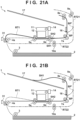
- Fig. 21A shows an example of the start timing of reduction control.
- the trailing edge of the preceding sheet SH1 has passed the conveyor roller 6a.
- the conveyor motor 25 rotates the conveyor rollers 8a and 7a at the velocity V2.
- Fig. 21B shows the timing at which the reduction control is terminated. As shown in Fig. 21B , the trailing edge of the preceding sheet SH1 and the leading edge of the succeeding sheet SH2 are separated on the two sides of the conveyor roller 7a.
- Rollers to be used in reduction control can also be the conveyor rollers 5a and 8a.
- the conveyor roller 8a is driven independently of the conveyor roller 7a, by using a dedicated motor that is not shared with the conveyor roller 7a.
- the conveyor rollers 6a and 7a are one-way rollers and capable of idling in the conveyance direction.
- the position T shown in Fig. 18A matches the conveyor roller 8a.
- the length L of the separation region is the distance from the conveyor roller 5a to the conveyor roller 8a.
- Fig. 22A shows an example of the start timing of reduction control in this embodiment.
- the trailing edge of the preceding sheet SH1 has passed the conveyor roller 5a but exists on the upstream side of the conveyor roller 6a.
- the conveyor roller 8a is rotated at the velocity V2 by the dedicated motor. Since the conveyor rollers 6a and 7a are one-way rollers, the preceding sheet SH1 can be conveyed without receiving any large load from these rollers.
- Fig. 22B shows the timing at which the reduction control is terminated. As shown in Fig. 22B , the trailing edge of the preceding sheet SH1 and the leading edge of the succeeding sheet SH2 are separated.
- Rollers to be used in reduction control can also be the conveyor rollers 5a and 9a, although this use is limited to the conveyance of the sheet SH1 in the sub-conveyance route RT2.
- the conveyor rollers 6a and 7a are one-way rollers and capable of idling in the conveyance direction.
- the position T shown in Fig. 18A matches the branch point BP.
- the length L of the separation region is the distance from the conveyor roller 5a to the branch point BP.
- Fig. 23A shows an example of the start timing of reduction control in this embodiment.
- the trailing edge of the preceding sheet SH1 has passed the conveyor roller 5a but exists on the upstream side of the conveyor roller 6a.
- the conveyor roller 9a is rotated at the velocity V2. Since the conveyor rollers 6a and 7a are one-way rollers, the preceding sheet SH1 can be conveyed without receiving any large load from these rollers.
- Fig. 23B shows the timing at which the reduction control is terminated. As shown in Fig. 23B , the trailing edge of the preceding sheet SH1 and the leading edge of the succeeding sheet SH2 are separated.
- an overlap amount adjusting operation of adjusting the overlap amount so as to reduce it can also be performed.
- the velocity V2 during reduction control can be set at a lower velocity.
- skew correction of the succeeding sheet SH is not performed when printing the last line of the preceding sheet SH, but is performed after the last line is printed and the preceding sheet SH is conveyed by a predetermined amount. This can reduce the overlap amount.
- the velocity of a conveyor roller for conveying the succeeding sheet SH can be controlled to be lower than a normal velocity.
- Embodiment(s) of the present invention can also be realized by a computer of a system or apparatus that reads out and executes computer executable instructions (e.g., one or more programs) recorded on a storage medium (which may also be referred to more fully as a 'non-transitory computer-readable storage medium') to perform the functions of one or more of the above-described embodiment(s) and/or that includes one or more circuits (e.g., application specific integrated circuit (ASIC)) for performing the functions of one or more of the above-described embodiment(s), and by a method performed by the computer of the system or apparatus by, for example, reading out and executing the computer executable instructions from the storage medium to perform the functions of one or more of the above-described embodiment(s) and/or controlling the one or more circuits to perform the functions of one or more of the above-described embodiment(s).
- computer executable instructions e.g., one or more programs
- a storage medium which may also be referred to more fully as
- the computer may comprise one or more processors (e.g., central processing unit (CPU), micro processing unit (MPU)) and may include a network of separate computers or separate processors to read out and execute the computer executable instructions.
- the computer executable instructions may be provided to the computer, for example, from a network or the storage medium.
- the storage medium may include, for example, one or more of a hard disk, a random-access memory (RAM), a read only memory (ROM), a storage of distributed computing systems, an optical disk (such as a compact disc (CD), digital versatile disc (DVD), or Blu-ray Disc (BD) TM ), a flash memory device, a memory card, and the like.
Landscapes
- Engineering & Computer Science (AREA)
- Mechanical Engineering (AREA)
- Delivering By Means Of Belts And Rollers (AREA)
- Separation, Sorting, Adjustment, Or Bending Of Sheets To Be Conveyed (AREA)
- Registering Or Overturning Sheets (AREA)
Abstract
Description
- The present invention relates to a printing apparatus.
- A printing apparatus in which a preceding print medium and a succeeding print medium are conveyed in an overlap state in which the leading edge portion of the succeeding print medium overlaps the preceding print medium and printing is performed on the succeeding print medium is known. After the overlap portion passes a printhead, it is sometimes desirable to cancel the overlap state or reduce the overlap amount from the viewpoints of the dischargeability of the print medium and making the apparatus jam-proof.
Japanese Patent Laid-Open No. 6-56299 - Unfortunately, in this method of canceling the overlap state by increasing the conveyance velocity of the preceding print medium, it is sometimes necessary to perform conveyance at a very high speed depending on the dimensions of a conveyance route of the print medium. This is disadvantageous in terms of noise and power consumption.
- The present invention provides a technique that reduces the overlap amount of a preceding print medium and a succeeding print medium while the conveyance velocity of the preceding print medium is kept low.
- The present invention in a first aspect provides a printing apparatus as specified in
claims 1 to 21. - The present invention in a second aspect provides a control method as specified in
claim 22. - Further features of the present invention will become apparent from the following description of exemplary embodiments (with reference to the attached drawings).
-
-
Fig. 1 is a schematic view of a printing apparatus according to an embodiment of the present invention; -
Fig. 2 is a block diagram of a control unit of the printing apparatus shown inFig. 1 ; -
Figs. 3A and 3B are views showing examples of the printing conditions; -
Figs. 4A and 4B are views for explaining the operation of the printing apparatus shown inFig. 1 ; -
Figs. 5A and 5B are views for explaining the operation of the printing apparatus shown inFig. 1 ; -
Figs. 6A and 6B are views for explaining the operation of the printing apparatus shown inFig. 1 ; -
Figs. 7A and 7B are views for explaining the operation of the printing apparatus shown inFig. 1 ; -
Figs. 8A and 8B are views for explaining the operation of the printing apparatus shown inFig. 1 ; -
Figs. 9A and 9B are views for explaining the operation of the printing apparatus shown inFig. 1 ; -
Figs. 10A and 10B are views for explaining the operation of the printing apparatus shown inFig. 1 ; -
Figs. 11A and 11B are views for explaining the operation of the printing apparatus shown inFig. 1 ; -
Figs. 12A and 12B are views for explaining the operation of the printing apparatus shown inFig. 1 ; -
Figs. 13A and 13B are views for explaining the operation of the printing apparatus shown inFig. 1 ; -
Figs. 14A and 14B are views for explaining the operation of the printing apparatus shown inFig. 1 ; -
Fig. 15 is a flowchart showing a processing example of the control unit shown inFig. 2 ; -
Fig. 16 is a flowchart showing a processing example of the control unit shown inFig. 2 ; -
Fig. 17 is a flowchart showing a processing example of the control unit shown inFig. 2 ; -
Figs. 18A to 18C are views for explaining reduction control; -
Figs. 19A to 19C are views for explaining the reduction control; -
Fig. 20 is a flowchart showing a processing example of the control unit shown inFig. 2 ; -
Figs. 21A and 21B are views for explaining the operation of the printing apparatus, and show an example of another reduction control; -
Figs. 22A and 22B are views for explaining the operation of the printing apparatus, and show an example of still another reduction control; and -
Figs. 23A and 23B are views for explaining the operation of the printing apparatus, and show an example of still another reduction control. - Hereinafter, embodiments will be described in detail with reference to the attached drawings. Note, the following embodiments are not intended to limit the scope of the claimed invention. Multiple features are described in the embodiments, but limitation is not made to an invention that requires all such features, and multiple such features may be combined as appropriate. Furthermore, in the attached drawings, the same reference numerals are given to the same or similar configurations, and redundant description thereof is omitted.
-
Fig. 1 is a schematic views of aprinting apparatus 1 according to this embodiment. In this embodiment, a case will be described in which the present invention is applied to a serial type inkjet printing apparatus, but the present invention is also applicable to printing apparatuses of other types. In the drawings, an arrow X and an arrow Y indicate horizontal directions orthogonal to each other, and an arrow Z indicates a vertical direction. A downstream side and an upstream side are based on the conveyance direction of a print medium. - Note that "printing" includes not only forming significant information such as characters and graphics but also forming images, figures, patterns, and the like on print media in a broad sense, or processing print media, regardless of whether the information formed is significant or insignificant or whether the information formed is visualized so that a human can visually perceive it. In addition, although in this embodiment, sheet-like paper is assumed as a "print medium" serving as a print target, sheet-like cloth, a plastic film, and the like may be used as print media.
- A
printing apparatus 1 is an apparatus that performs printing on sheets SH as print media stacked in a feed tray (stacker) 2, and discharges the sheets SH to adischarge tray 17. A main conveyance route RT1 for guiding the conveyance of the sheets SH is formed from thefeed tray 2 to thedischarge tray 17, and the sheets SH in thefeed tray 2 are supplied one by one to the main conveyance route RT1 by apickup roller 3. Thepickup roller 3 is rotated by the driving force of afeed motor 22. Note that in the main conveyance route RT1 schematically shown in each drawing, there is only one route between afeed unit 4 and aconveyance unit 5, but upper and lower routes extending along upper and lower conveyance guides are shown. - The
printing apparatus 1 also includes a sub-conveyance route RT2 branched by a branch point BP from the main conveyance route RT1. The sub-conveyance route RT2 is a route for inverting the obverse and reverse surfaces of the sheet SH and returning the sheet SH to the main conveyance route RT1, and is used when performing double-sided printing on the sheet SH. Note that theprinting apparatus 1 need not have the double-sided printing function for the sheet SH, and the sub-conveyance route RT2 and its relevant arrangement are unnecessary in this case. - The
printing apparatus 1 includes thefeed unit 4 and a plurality ofconveyance units 5 to 10. Thefeed unit 4 and the plurality ofconveyance units 5 to 8 are arranged along the main conveyance route RT1. Thefeed unit 4, theconveyance unit 5, theconveyance unit 6, theconveyance unit 7, and theconveyance unit 8 are arranged in this order from the upstream side to the downstream side in the conveyance direction of the sheet SH in the main conveyance route RT1. Theconveyance units - Note that in the following explanation, the upstream side and the downstream side mean the upstream side and the downstream side in the conveyance direction of the sheet SH in the main conveyance route RT1, unless otherwise specified. Note also that the leading edge and trailing edge of the sheet SH mean the downstream edge and upstream edge of the sheet SH.
- The
feed unit 4 feeds the sheet SH supplied to the main conveyance route RT1 by thepickup roller 3, or the sheet SH returned from the sub-conveyance route RT2 to the main conveyance route RT1, to theconveyance unit 5. Thefeed unit 4 includes afeed roller 4a, and a drivenroller 4b that is urged against thefeed roller 4a by a spring or the like (not shown). Thefeed roller 4a is a rotational member that rotates by the driving force of afeed motor 23, and the drivenroller 4b is a rotational member that rotates following the rotation of thefeed roller 4a. - The sheet SH is nipped by a nip portion between the driving
roller 4a and the drivenroller 4b, and conveyed by the rotations of the drivingroller 4a and the drivenroller 4b. Note that thepickup roller 3 is a one-way roller. Therefore, after the sheet SH is conveyed to a position exceeding the nip portion of thefeed unit 4, conveyance by thefeed unit 4 can be continued even when driving of thepickup roller 3 is stopped. - Note that this embodiment includes the
pickup roller 3 and thefeed roller 4a, but it is also possible to use only thefeed roller 4a for feeding the sheets SH stacked in thefeed tray 2. - A
sensor 31 is a sensor for detecting the passing of the leading edge and trailing edge of the sheet SH, and is an optical sensor or the like. The detection position of thesensor 31 is set in a position on the downstream side of the nip portion of thefeed unit 4. - The
conveyance unit 5 is arranged on the upstream side of aprinthead 12, and conveys the sheet SH fed by thefeed unit 4 to theprinthead 12. Theconveyance unit 5 conveys the sheet SH to the downstream side between theprinthead 12 and aplaten 15 facing theprinthead 12. Theconveyance unit 5 includes aconveyor roller 5a, and a driven roller (pinch roller) 5b that is urged against theconveyor roller 5a by a spring or the like (not shown). Theconveyor roller 5a is a rotational member that rotates by the driving force of aconveyor motor 24, and the drivenroller 5b is a rotational member that rotates following the rotation of theconveyor roller 5a. The sheet SH is nipped by a nip portion between theconveyor roller 5a and the drivenroller 5b, and conveyed by the rotations of theconveyor roller 5a and the drivenroller 5b. - The
conveyance unit 6 is arranged on the downstream side of theprinthead 12, and conveys the sheet SH conveyed by theconveyance unit 5 to the downstream side. Theconveyance unit 6 includes aconveyor roller 6a, and aspur 6b that is urged against theconveyor roller 6a by a spring or the like (not shown). Theconveyor roller 6a is a rotational member that rotates by the driving force of theconveyor motor 24, and thespur 6b is a rotational member that rotates following the rotation of theconveyor roller 6a. In this embodiment, theconveyance units - The
conveyance unit 7 is arranged on the downstream side of theprinthead 12 and theconveyance unit 6, and conveys the sheet SH conveyed by theconveyance unit 6 to the downstream side. Theconveyance unit 7 includes aconveyor roller 7a, and a drivenroller 7b that is urged against theconveyor roller 7a by a spring or the like (not shown). Theconveyor roller 7a is a rotational member that rotates by the driving force of aconveyor motor 25, and the drivenroller 7b is a rotational member that rotates following the rotation of theconveyor roller 7a. The sheet SH is nipped by a nip portion between theconveyor roller 7a and the drivenroller 7b, and conveyed by the rotations of theconveyor roller 7a and the drivenroller 7b. - The
conveyance unit 8 is arranged on the downstream side of theprinthead 12 and theconveyance units conveyance unit 7 to thedischarge tray 17. Theconveyance unit 8 includes aconveyor roller 8a, and a drivenroller 8b that is urged against theconveyor roller 8a by a spring or the like (not shown). Theconveyor roller 8a is a rotational member that rotates by the driving force of theconveyor motor 25, and the drivenroller 8b is a rotational member that rotates following the rotation of theconveyor roller 8a. The sheet SH is nipped by a nip portion between theconveyor roller 8a and the drivenroller 8b, and conveyed by the rotations of theconveyor roller 8a and the drivenroller 8b. In this embodiment, theconveyance units - A
flapper 16 is arranged in the branch point BP. Theflapper 16 switches the routes to the conveyance destinations of the sheet SH between the main conveyance route RT1 and the sub-conveyance route RT2. In the position shown inFig. 1 , theflapper 16 maintains the route to the conveyance destination of the sheet SH to the main conveyance route RT1, and the sheet SH is discharged to thedischarge tray 17 via theconveyance unit 8. Theflapper 16 is formed to be able to pivot, and switches the routes by pivoting by anactuator 27 such as an electromagnetic solenoid. - The
conveyance unit 9 is an inversion unit for conveying the sheet SH having entered the sub-conveyance route RT2 from the branch point BP. The sub-conveyance route RT2 has an inversion route RT21 extending upward from the branch point BP via a branch point BP', and a return route RT22 extending from the branch point BP' to thefeed unit 4. Theconveyance unit 9 is arranged in the inversion route RT21. - The
conveyance unit 9 includes aconveyor roller 9a, and a drivenroller 9b that is urged against theconveyor roller 9a by a spring or the like (not shown). Theconveyor roller 9a is a rotational member that rotates by the driving force of aconveyor motor 26, and the drivenroller 9b is a rotational member that rotates following the rotation of theconveyor roller 9a. - The sheet SH having entered the sub-conveyance route RT2 from the branch point BP moves in the inversion route RT21. The
conveyor roller 9a is rotated in two directions, that is, a direction R1 and an opposite direction R2. When theconveyor roller 9a rotates in the direction R1, the sheet SH is conveyed in the direction of an arrow F. When the trailing edge of the sheet SH passes the branch point BP', the rotational direction of theconveyor roller 9a is switched to the direction R2. The sheet SH is conveyed in the opposite direction. The sheet SH is supplied from the branch point BP' to the return route RT22 while the obverse and reverse surfaces of the sheet SH are inverted. - The
conveyance unit 10 is an intermediate unit arranged in the return route RT22. Theconveyance unit 10 includes aconveyor roller 10a, and a drivenroller 10b that is urged against theconveyor roller 10a by a spring or the like (not shown). Theconveyor roller 10a is a rotational member that rotates by the driving force of theconveyor motor 26, and the drivenroller 10b is a rotational member that rotates following the rotation of theconveyor roller 10a. The sheet SH is nipped by a nip portion between theconveyor roller 10a and the drivenroller 10b, and conveyed by the rotations of theconveyor roller 10a and the drivenroller 10b. In this embodiment, theconveyance units conveyor roller 10a is a one-way roller. Therefore, after the sheet SH is conveyed to a position exceeding the nip portion of thefeed unit 4, conveyance by thefeed unit 4 can be continued even when driving of theconveyor roller 10a is stopped. - The
printhead 12 is arranged midway along the main conveyance route RT1. In this embodiment, theprinthead 12 is arranged in a position on the downstream side of theconveyance unit 5 and on the upstream side of theconveyance unit 6. Theprinthead 12 performs printing on the sheet SH. The sheet SH is conveyed in the X direction in the vicinity of theprinthead 12. In this embodiment, theprinthead 12 is an inkjet printhead that performs printing on a print medium by ejecting ink. Theprinthead 12 is supported by acarriage 11. - The
carriage 11 is moved back and forth by a drivingunit 14 in a direction crossing the sheet SH (a direction crossing the conveyance direction of the sheet SH in the vicinity of the printhead 12). In this embodiment, thecarriage 11 moves back and forth in the Y direction by being guided by aguide shaft 13 extended in the Y direction. - The driving
unit 14 is a mechanism using acarriage motor 21 as a driving source, and is a transmission mechanism including a driving pulley and a driven pulley separated in the Y direction, and an endless belt wound around these pulleys. Thecarriage 11 is connected to the endless belt. When thecarriage motor 21 rotates the driving pulley, the endless belt runs and thecarriage 11 moves. Theprinthead 12 can also be attached to thecarriage 11 so that theprinthead 12 can be exchanged. - As described above, the
printing apparatus 1 of this embodiment is a serial-type printing apparatus in which theprinthead 12 is mounted on thecarriage 11. Printing control on the sheet SH is performed by alternately repeating an intermittently performed conveyance operation (intermittent conveyance operation) in which theconveyance unit 5 and/or theconveyance unit 6 conveys a print medium by a predetermined amount, and a printing operation that is performed while the conveyance by theconveyance unit 5 and/or theconveyance unit 6 is stopped. The printing operation is an operation of ejecting ink from theprinthead 12 while moving thecarriage 11 on which theprinthead 12 is mounted. -
Fig. 2 is a block diagram of acontrol unit 40 of theprinting apparatus 1. AnMPU 41 is a processor for controlling each operation of theprinting apparatus 1 and controlling data processing and the like. TheMPU 41 controls thewhole printing apparatus 1 by executing a program stored in astorage device 42. Thestorage device 42 is, for example, a ROM or a RAM. Thestorage device 42 stores the program to be executed by theMPU 41, and also stores various kinds of data necessary for processing, such as data received from ahost computer 100. - The
MPU 41 controls theprinthead 12 via adriver 44a. TheMPU 41 controls thecarriage motor 21 via adriver 44b. TheMPU 41 also controls thefeed motors conveyor motors 24 to 26, and theactuator 27 viadrivers 44c to 44i. - A
sensor group 30 includes thesensor 31, a sensor (not shown) for detecting the position of thecarriage 11 in the Y direction, and sensors (not shown) for detecting the rotation amounts of thefeed motors conveyor motors 24 to 26. By detecting the rotation amount of each motor, it is possible to specify the rotation amount of a corresponding feed roller or conveyor roller, and calculate the conveyance amount of the sheet SH. - The
host computer 100 is, for example, a personal computer or a portable terminal (for example, a smartphone or a tablet terminal) that is used by the user. Aprinter driver 100a for performing communication between thehost computer 100 and theprinting apparatus 1 is installed in thehost computer 100. Theprinting apparatus 1 includes an I/F (interface)unit 43, and the communication between thehost computer 100 and theMPU 41 is executed via the I/F unit 43. - In a case where, for example, the user inputs execution of printing control to the
host computer 100, theprinter driver 100a generates a print job by gathering data of an image to be printed, and the printing conditions (various pieces of information such as the quality of a printed image), and transmits the print job to theprinting apparatus 1. - An example of control to be executed by the
MPU 41 will be explained below. When thehost computer 15 transmits a print job via the I/F unit 43, theMPU 41 processes the print job and expands the processed data on thestorage device 42. TheMPU 41 starts the control based on the expanded data. -
Figs. 3A and 3B show examples of printing conditions related to the conveyance operation of the sheet SH, among printing conditions contained in the print job. Theprinting apparatus 1 of this embodiment can perform both single-sided printing and double-sided printing.Fig. 3A shows an example of printing conditions when performing double-sided printing on two sheets SH, andFig. 3B shows an example of printing conditions when performing single-sided printing on three sheets SH. Note that as a printing order, a facedown method in which an immediately preceding printing surface in a facedown state is discharged to thedischarge tray 17 is assumed, but a faceup method is also usable. - "Printing Order N" indicates the number of times and the order of printing control for one surface of the sheet SH, and N is a variable. Printing control is executed for four surfaces (four times) in the example shown in
Fig. 3A , and three surfaces (three times) in the example shown inFig. 3B . - "Page Number K" indicates a page of the final printed product to which the printing order N corresponds, and K is a variable. "Sheet M" indicates a target sheet SH of the printing order N, and M is a variable. In this embodiment, a number is given in the order of feed from the
feed tray 2. A sheet SH1 indicates the sheet SH fed first from thefeed tray 2 in the print job, a sheet SH2 indicates the sheet SH fed second from thefeed tray 2, and a sheet SH3 indicates the sheet SH fed third from thefeed tray 2. - The variable M is sometimes represented as M(N) as a function of the printing order N. In the example shown in
Fig. 3A , M(1) means the sheet SH1, M(2) means the sheet SH2, and M(3) means the sheet SH1. In the example shown inFig. 3B , M(3) means the sheet SH3. - "Printing Surface F" indicates which one of the obverse and reverse surfaces (in other words, the first and second surfaces) of the sheet SH is a printing target surface, and is sometimes represented as F(N) as a function of the printing order N. In the example shown in
Fig. 3A , F(1) means that the reverse surface of the sheet SH1 is a printing target surface, and F(3) means that the obverse surface of the sheet SH1 is a printing target surface. - "Feed Source Q" indicates which of the
feed tray 2 or the sub-conveyance route RT2 is the feed source of the sheet SH, and is sometimes represented as Q(N) as a function of the printing order N. When performing double-sided printing in this embodiment, after the reverse surface is printed, the sheet SH is inverted in the inversion route RT21 of the sub-conveyance route RT2, and returned to thefeed unit 4 via the return route RT22. In double-sided printing, thefeed tray 2 or the sub-conveyance route RT2 is the feed source. In single-sided printing, thefeed tray 2 is always the feed source. - "Post-Printing Processing G" indicates whether the processing of the printing sheet SH is discharge to the
discharge tray 17 or inversion in the sub-conveyance route RT2, and is sometimes represented as G(N) as a function of the printing order N. In single-sided printing, the processing G is always discharge. In double-sided printing, the processing G is inversion after the first surface is printed, and is discharge after the second surface is printed. - Operation examples of the
printing apparatus 1 will be explained below with reference toFigs. 4A to 14B . More specifically, operation examples when performing double-sided printing on two sheets SH in accordance with the printing conditions shown inFig. 3A will be explained. - Referring to
Fig. 4A , since the printing conditions shown inFig. 3A indicate double-sided printing, theflapper 16 is moved beforehand so as to guide the sheet SH to the sub-conveyance route RT2. Thefeed motor 22 is driven at low speed. Consequently, thepickup roller 3 is rotated at, for example, 7.6 inches/sec (the conveyance velocity of the sheet SH, and the same expression has the same meaning hereinafter). When thepickup roller 3 rotates, the uppermost one of the sheets SH stacked in thefeed tray 2 is picked up. This sheet is represented as a sheet SH1. - The sheet SH1 picked up by the
pickup roller 3 is conveyed in the main conveyance route RT1 by thefeed roller 4a rotating in the same direction as thepickup roller 3. Thefeed motor 23 drives thefeed roller 4a at the same speed as thepickup roller 3. Thepickup roller 3 conveys the sheet SH1 to a position exceeding thefeed roller 4a, and stops so as not to pick up the next sheet SH. As described above, thepickup roller 3 is a one-way roller, so thefeed roller 4a can continue feeding even when thepickup roller 3 stops. - When the
sensor 31 installed on the downstream side in the conveyance direction of thefeed roller 4a detects the leading edge of the sheet SH1, thefeed motor 23 is switched to high-speed driving. Thefeed roller 4a rotates at, for example, 20 inches/sec. - Referring to
Fig. 4B , when thefeed roller 4a continues feeding of the sheet SH1, the leading edge of the sheet SH1 abuts against the nip portion formed by theconveyor roller 5a and thepinch roller 5b. In this state, theconveyor roller 5a is standing still. By rotating thefeed roller 4a by a predetermined amount even after the leading edge of the sheet SH1 abuts against the nip portion, the whole widthwise region of the leading edge of the sheet SH1 abuts against the nip portion, so a skew of the sheet SH1 can be corrected (a skew correcting operation). - When this skew correcting operation on the sheet SH1 is complete, the
conveyor motor 24 is driven, so theconveyor roller 5a starts rotating. Theconveyor roller 5a conveys the sheet SH1 at, for example, 15 inches/sec. Printing control can be started when the sheet SH1 is aligned in the position facing theprinthead 12. As indicated by the condition N = 1 inFig. 3A , an operation of printing print data of the second page is started on the reverse surface (upper surface) of the sheet SH1. - Note that when the leading edge of the sheet SH1 is abutted against the nip portion of the
conveyance unit 5, the leading edge of the sheet SH1 is positioned once in the position of theconveyor roller 5a. Based on this position, the positions of the leading edge and trailing edge of the sheet SH1 can be calculated by the rotation amount of theconveyor roller 5a after that. This position control conveys the sheet SH1 to the position facing theprinthead 12 in alignment as well. - As described above, the
printing apparatus 1 of this embodiment is a serial-type printing apparatus in which theprinthead 12 is mounted on thecarriage 11. Printing on the sheet SH1 is performed by repeating a conveyance operation in which theconveyor roller 5a intermittently conveys a print medium by a predetermined amount each time, and a printing operation in which theprinthead 12 ejects ink while thecarriage 11 is moved. When the sheet SH1 is aligned, thefeed motor 23 is switched to low-speed driving. That is, thefeed roller 4a rotates at, for example, 7.6 inches/sec. While theconveyor roller 5a is intermittently conveying the sheet SH1 by the predetermined amount each time, thefeed motor 23 also intermittently drives thefeed roller 4a. That is, thefeed roller 4a rotates when theconveyor roller 5a rotates, and thefeed roller 4a is standing still when theconveyor roller 5a is standing still. The rotational speed of thefeed roller 4a is lower than that of theconveyor roller 5a. Accordingly, the sheet SH is pulled tight between theconveyor roller 5a and thefeed roller 4a. Also, thefeed roller 4a is co-rotated by theconveyor roller 5a via the sheet SH1. - When printing on the sheet SH1 advances, the leading edge of the sheet SH1 arrives at the
conveyance unit 6. Since theconveyor roller 6a shares theconveyor motor 24 as a driving source with theconveyor roller 5a, synchronous control is performed.Fig. 5B shows a state in which the leading edge of the sheet SH1 has passed theconveyor roller 6a. - Then, feeding of the sheet SH2 is started following the sheet SH1. To detect the edge portion of the sheet SH, the
sensor 31 requires a predetermined interval between successive sheets SH due to a cause such as the responsiveness of the sensor. Accordingly, the pickup operation of the sheet SH2 is started after the trailing edge of the sheet SH1 is detected by thesensor 16 and it is determined that the sheet SH1 has passed thesensor 16. Also, when feeding the sheet SH2, the rotation of thepickup roller 3 is so controlled that the interval between the trailing edge of the sheet SH1 and the leading edge of the sheet SH2 is a predetermined distance or more. In this embodiment, the positions of the leading edge and trailing edge of the sheet SH are specified by calculations based on the rotation amounts of the various rollers. However, these positions can also be calculated by installing another sensor. - Referring to
Fig. 5B , the trailing edge of the sheet SH1 has passed thefeed roller 4a and is slightly hanging down. The sheet SH2 picked up by thepickup roller 3 is conveyed by thefeed roller 4a. In this state, printing control is executed in parallel on the sheet SH1. When thesensor 31 detects the leading edge of the sheet SH2, thefeed motor 23 is switched to high-speed driving. That is, thefeed roller 4a rotates at, for example, 20 inches/sec. - Note that while the
conveyor rollers conveyor motors conveyor rollers conveyor roller 5a. - In this embodiment, overlap state formation control can be executed. Referring to
Fig. 6A , the sheet SH2 is fed at a speed higher than the conveyance velocity of the sheet SH1, thereby forming an overlap state in which the leading edge of the sheet SH2 overlaps the trailing edge of the sheet SH1 before theconveyor roller 5a. Since printing control is performed on the sheet SH1 based on the print data, theconveyor roller 5a intermittently conveys the sheet SH1. On the other hand, after the trailing edge of the sheet SH2 is detected by thesensor 31, the sheet SH2 can catch up with the sheet SH1 by continuously rotating thefeed roller 4a at 20 inches/sec. After that, the sheet SH2 is conveyed until the leading edge arrives at a predetermined position slightly before the nip portion of theconveyance unit 5. The position of the leading edge of the sheet SH2 is calculated from the rotation amount of thefeed roller 4a since the leading edge of the sheet SH2 is detected by thesensor 31, and is controlled based on this calculation result. The sheet SH1 has entered the sub-conveyance route RT2 by being guided by theflapper 16. - Then, a skew correcting operation is performed on the sheet SH2. While the
conveyor roller 5a is standing still in order to perform the printing operation on the sheet SH1, the leading edge of the sheet SH2 is abutted against the nip portion by driving thefeed roller 4a. In this embodiment, the skew correcting operation for the sheet SH2 is performed while theconveyor roller 5a is standing still for the printing operation for the last line of the sheet SH1, in order to minimize the influence on the printing quality of the sheet SH1. - Referring to
Fig. 6B , when the printing operation for the last line of the sheet SH1 is complete, the sheet SH2 can be aligned while maintaining the state in which the sheet SH2 overlaps the sheet SH1 by rotating theconveyor roller 5a by a predetermined amount. Note that the overlap portion of the sheets SH1 and SH2 is conveyed as it is nipped by the nip portion of theconveyance unit 5. - When the sheet SH2 is aligned, the
feed motor 23 is switched to low-speed driving. That is, thefeed roller 4a rotates at, for example, 7.6 inches/sec. While theconveyor roller 5a is intermittently conveying the sheet SH2 by a predetermined amount each time, thefeed motor 23 also intermittently drives thefeed roller 4a. As indicated by the condition N = 2 inFig. 3A , an operation of printing the print data of the fourth page is performed on the reverse surface (upper surface) of the sheet SH2. When the sheet SH2 is intermittently conveyed for this printing operation, the sheet SH1 is also intermittently conveyed. - In this embodiment, overlap amount reduction control can be executed. When the overlap portion of the sheets SH1 and SH2 passes the branch point BP, a paper jam may occur. For example, when the sheets SH1 and SH2 are conveyed to different routes from the branch point BP, the sheet SH2 may interfere with the sheet SH1 and cause a paper jam depending on the vertical relationship between the sheets SH1 and SH2. An example is a case in which while the sheet SH1 passes the branch point BP along the main conveyance route RT1, the succeeding sheet SH2 overlapping the sheet SH1 is conveyed to the sub-conveyance route RT2.
- Accordingly, reduction control for reducing the overlap amount is performed before the overlap portion arrives at the branch point BP (in other words, before the sheet SH2 arrives at the branch point BP). In this embodiment, the overlap amount is reduced to 0. However, even when the overlap amount is not reduced to 0, a predetermined effect can be obtained if the overlap amount can be reduced.
- Referring to
Fig. 7A , whether the trailing edge of the sheet SH1 has passed theconveyor roller 6a is determined from the rotation amount of theconveyor roller 5a since the start of the operation of aligning the sheet SH1, and from the length of the sheet SH1. As shown inFig. 7A , at the timing at which the trailing edge of the sheet SH1 passes theconveyor roller 6a, theconveyor roller 7a can convey the preceding sheet SH1, and theconveyor rollers conveyor rollers conveyor roller 7a has no influence on the conveyance of the sheet SH2. At this timing, reduction control is started. - In this reduction control, the
conveyor motor 25 continuously rotates theconveyor roller 7a independently of theconveyor rollers conveyor roller 9a is rotated by theconveyor roller 26 at the same speed as that of theconveyor roller 7a in the R1 direction (seeFig. 1 ) - As shown in
Fig. 7B , the trailing edge of the sheet SH1 can be separated from the sheet SH2 by the relative speed difference between the sheets SH1 and SH2. In this case, the speed of theconveyor roller 7a is controlled such that the reduction control can be completed before the trailing edge of the preceding sheet SH1 passes theconveyor roller 7a. Note that an example of this speed control will be described later. - The reduction control as described above can prevent the overlap portion of the sheets SH1 and SH2 from passing the branch point BP, thereby preventing the occurrence of a paper jam. Since the reduction control is executed during the printing control on the sheet SH2, the reduction control includes at least a control zone in which the
conveyor rollers conveyor roller 7a conveys the preceding sheet SH1. - That is, the conveyance of the sheet SH2 is stopped during its printing operation. By continuously conveying the sheet SH1 during this printing operation, it is possible to maximize the relative speed difference between the sheets SH1 and SH2, and efficiently reduce the overlap amount. Accordingly, the speed of the
conveyor roller 7a need not be higher than that of theconveyor roller 5a in order to reduce the overlap amount. The overlap amount of the sheets SH1 and SH2 can be reduced at a lower conveyance velocity of the sheet SH1. In other words, when the reduction control is performed during the printing operation, it is possible to reduce the conveyance velocity and suppress deterioration of the noise and electric power, compared to a case in which no reduction control is performed during the printing operation. In addition, if the reduction control is not completed during the printing operation of the sheet SH2, the reduction control can be performed during the conveyance operation of the sheet SH2 as well. In this case, the overlap amount can effectively be reduced because the speed of theconveyor roller 7a is higher than that of theconveyor roller 5a. It is, of course, needless to say that the reduction control can also be performed even when it is completed during the printing operation of the sheet SH2. - Referring to
Fig. 8A , theconveyor roller 9a continuously conveys the sheet SH1 to a position where the trailing edge of the sheet SH1 passes the branch point BP'. When the trailing edge of the sheet SH1 passes the branch point BP', theconveyor motor 26 is reversed to the direction R2 (seeFig. 1 ), thereby switching driving to high-speed driving. In this conveyance direction, the leading edge and trailing edge of the sheet SH1 are switched. Theconveyor rollers feed roller 4a as shown inFig. 8B . - When the conveyance of the sheet SH1 advances and the
sensor 31 detects the leading edge of the sheet SH1, theconveyor motor 26 and thefeed motor 23 are driven at low speed. Consequently, theconveyor roller 10a and thefeed roller 4a are rotated at, for example, 7.6 inches/sec. Then, theconveyor roller 10a and thefeed roller 4a convey the sheet SH1 from the return route RT22 to the main conveyance route RT1. - Subsequently, overlap state formation control is performed. Referring to
Fig. 9A , the sheet SH2 is the preceding sheet and the sheet SH1 is the succeeding sheet, unlike in the case shown inFig. 6A . Printing control is performed on the sheet SH2 based on the print data. When thesensor 31 detects the trailing edge of the sheet SH2, theconveyor motor 26 and thefeed motor 23 are switched to high-speed driving. That is, theconveyor roller 10a and thefeed roller 4a rotate at, for example, 20 inches/sec. An overlap state in which the leading edge of the sheet SH1 overlaps the trailing edge of the sheet SH2 is formed by rapidly moving the sheet SH1. Since printing control is performed on the sheet SH2 based on the print data, theconveyor roller 5a intermittently conveys the sheet SH2. On the other hand, after thesensor 31 detects the trailing edge of the sheet SH1, the sheet SH1 can catch up with the sheet SH2 by continuously rotating thefeed roller 4a at 20 inches/sec. After that, the sheet SH1 is conveyed until its leading edge arrives at a predetermined position slightly before the nip portion of theconveyance unit 5. The position of the leading edge of the sheet SH1 is calculated from the rotation amount of thefeed roller 4a since thesensor 31 detects the leading edge of the sheet SH1, and controlled based on the calculation result. The sheet SH2 enters the sub-conveyance route RT2 by being guided by theflapper 16. - Then, a skew correcting operation of the sheet SH1 is performed. When the
conveyor roller 5a is standing still in order to perform the printing operation on the sheet SH2, the leading edge of the sheet SH1 is abutted against the nip portion by driving thefeed roller 4a. In this embodiment, the skew correcting operation of the sheet SH1 is performed when theconveyor roller 5a is standing still in order to perform the operation of printing the last line on the sheet SH2, in order to minimize the influence on the printing quality of the sheet SH2. - Referring to
Fig. 9B , when the operation of printing the last line on the sheet SH2 is complete, the sheet SH1 can be aligned while maintaining the state in which the sheet SH1 overlaps the sheet SH2 by rotating theconveyor roller 5a by a predetermined amount. Note that the overlap portion of the sheets SH1 and SH2 is conveyed as it is nipped by the nip portion of theconveyance unit 5. - When the sheet SH1 is aligned, the
feed motor 23 is switched to low-speed driving. That is, thefeed roller 4a rotates at, for example, 7.6 inches/sec. When theconveyor roller 5a intermittently conveys the sheet SH2 by a predetermined amount each time, theconveyor motor 23 also intermittently drives thefeed roller 4a. An operation of printing the print data of the first page on the obverse surface (upper surface) of the sheet SH1 is started by ejecting ink from theprinthead 12 based on the print data. When the sheet SH1 is intermittently conveyed for this printing operation, the sheet SH2 is also intermittently conveyed. - Subsequently, overlap amount reduction control is performed. While the sheet SH2 is supplied to the sub-conveyance route RT2, the sheet SH1 is kept conveyed in the main conveyance route RT1 and discharged. At this timing, reduction control is performed again.
- Referring to
Fig. 10A , whether the trailing edge of the sheet SH2 has passed theconveyor roller 6a is determined from the rotation amount of theconveyor roller 5a since the start of the alignment operation on the sheet SH2, and from the length of the sheet SH2. As shown inFig. 10A , at the timing at which the trailing edge of the sheet SH1 passes theconveyor roller 6a, theconveyor roller 7a can convey the preceding sheet SH2, and theconveyor rollers conveyor rollers conveyor roller 7a has no influence on the conveyance of the sheet SH1. Reduction control is started at this timing. - In this reduction control, the
conveyor motor 25 continuously rotates theconveyor roller 7a independently of theconveyor rollers conveyor motor 26 rotates theconveyor roller 9a as well in the direction R1 (seeFig. 1 ) at the same speed as that of theconveyor roller 7a. - As shown in
Fig. 10B , the trailing edge of the sheet SH2 can be separated from the sheet SH1 by the relative speed difference between the sheets SH1 and SH2. In this case, the speed of theconveyor roller 7a is controlled so that the reduction control can be completed before the trailing edge of the preceding sheet SH2 passes theconveyor roller 7a. Note that an example of this speed control will be described later. - Since the reduction control is executed during the printing control of the sheet SH1, the reduction control includes at least a control zone in which the conveyance of the succeeding sheet SH1 by the
conveyor rollers conveyor roller 7a conveys the preceding sheet SH2. - That is, the conveyance of the sheet SH1 is stopped during its printing operation. By continuously conveying the sheet SH2 during this printing operation, it is possible to maximize the relative speed difference between the sheets SH2 and SH1, and efficiently reduce the overlap amount. The overlap amount of the sheets SH2 and SH1 can be reduced at a lower conveyance velocity of the sheet SH2. If the reduction control is not completed during the printing operation of the sheet SH2, the reduction control is performed during the conveyance operation of the sheet SH2. In this case, the overlap amount can effectively be reduced because the speed of the
conveyor roller 7a is higher than that of theconveyor roller 5a. - Referring to
Fig. 11A , theconveyor roller 9a continuously conveys the sheet SH2 to a position where its trailing edge passes the branch point BP'. When the trailing edge of the sheet SH2 passes theflapper 16, theflapper 16 is pivoted in accordance with a post-printing process of the sheet SH1 that passes theflapper 16 next. Since the post-printing process of the sheet SH1 is discharge, theflapper 16 moves to a position where the conveyance route of the sheet SH1 is maintained in the main conveyance route RT1. Whether the trailing edge of the sheet SH2 has passed theflapper 16 can be determined from the rotation amounts of the various rollers or by installing another sensor. - When the trailing edge of the sheet SH2 passes the branch point BP', the
conveyor motor 26 is reversed to the direction R2 (seeFig. 1 ), and driving is switched to high-speed driving. The leading edge and trailing edge of the sheet SH2 are switched in this conveyance direction. Theconveyor rollers feed roller 4a as shown inFig. 11B . - When the conveyance of the sheet SH2 advances and the
sensor 31 detects the leading edge of the sheet SH2, theconveyor motor 26 and thefeed motor 23 are driven at low speed. Consequently, theconveyor roller 10a and thefeed roller 4a are rotated at, for example, 7.6 inches/sec. Then, theconveyor roller 10a and thefeed roller 4a convey the sheet SH2 from the return route RT22 to the main conveyance route RT1. - Subsequently, overlap state formation control is performed. Referring to
Fig. 12A , the sheet SH1 is the preceding sheet and the sheet SH2 is the succeeding sheet again. Printing control is performed on the sheet SH1 based on the print data. When thesensor 31 detects the trailing edge of the sheet SH1, theconveyor motor 26 and thefeed motor 23 are switched to high-speed driving. That is, theconveyor roller 10a and thefeed roller 4a rotate at, for example, 20 inches/sec. An overlap state in which the leading edge of the sheet SH2 overlaps the trailing edge of the sheet SH1 is formed by rapidly moving the sheet SH2. Since the printing control is performed on the sheet SH1 based on the print data, theconveyor roller 5a intermittently conveys the sheet SH1. On the other hand, after thesensor 31 detects the trailing edge of the sheet SH2, the sheet SH2 can catch up with the sheet SH1 by continuously rotating thefeed roller 4a at 20 inches/sec. After that, the sheet SH2 is conveyed until its leading edge arrives at a predetermined position slightly before the nip portion of theconveyance unit 5. The position of the leading edge of the sheet SH2 is calculated from the rotation amount of thefeed roller 4a since thesensor 31 detects the leading edge of the sheet SH2, and is controlled based on the calculation result. The leading edge of the sheet SH1 passes the branch point BP and moves toward theconveyor roller 8a. - Then, a skew correcting operation of the sheet SH2 is performed. While the
conveyor roller 5a is standing still in order to perform the printing operation on the sheet SH1, the leading edge of the sheet SH2 is abutted against the nip portion by driving thefeed roller 4a. In this embodiment, the skew correcting operation of the sheet SH2 is performed while theconveyor roller 5a is standing still for an operation of printing the last line on the sheet SH1, in order to minimize the influence on the printing quality of the sheet SH1. - Referring to
Fig. 12B , when the operation of printing the last line on the sheet SH1 is complete, the sheet SH2 can be aligned while maintaining the state in which the sheet SH2 overlaps the sheet SH1 by rotating theconveyor roller 5a by a predetermined amount. Note that the overlap portion of the sheets SH1 and SH2 is conveyed as it is nipped by the nip portion of theconveyance unit 5. - When the sheet SH2 is aligned, the
feed motor 23 is switched to low-speed driving. That is, thefeed roller 4a rotates at, for example, 7.6 inches/sec. When theconveyor roller 5a intermittently conveys the sheet SH2 by a predetermined amount each time, thefeed motor 23 also intermittently drives thefeed roller 4a. An operation of printing the print data of the third page on the obverse surface (upper surface) of the sheet SH2 is started by ejecting ink from theprinthead 12 based on the print data. When the sheet SH2 is intermittently conveyed for this printing operation, the sheet SH1 is also intermittently conveyed. - Subsequently, overlap amount reduction control is performed. If the sheets SH1 and SH2 are discharged as they are largely overlapping each other, the stacking order of the sheets SH1 and SH2 on the
discharge tray 25 may be inverted. Therefore, overlap amount reduction control is performed. In this embodiment, the overlap amount is reduced to 0. However, even when the overlap amount is not reduced to 0, a predetermined effect is obtained if the overlap amount can be reduced. - Referring to
Fig. 13A , whether the trailing edge of the sheet SH1 has passed theconveyor roller 6a is determined from the rotation amount of theconveyor roller 5a since the start of the alignment operation on the sheet SH1, and from the length of the sheet SH1. As shown inFig. 13A , at the timing at which the trailing edge of the sheet SH1 passes theconveyor roller 6a, theconveyor roller 7a can convey the preceding sheet SH1, and theconveyor rollers conveyor rollers conveyor roller 7a has no influence on the conveyance of the sheet SH2. Reduction control is started at this timing. - In this reduction control, the
conveyor motor 25 continuously rotates theconveyor roller 7a independently of theconveyor rollers conveyor roller 8a sharing theconveyor motor 25 also continuously rotates. - As shown in
Fig. 13B , the trailing edge of the sheet SH1 can be separated from the sheet SH2 by the relative speed difference between the sheets SH1 and SH2. In this case, the speed of theconveyor roller 7a is controlled so that the reduction control can be completed before the trailing edge of the preceding sheet SH1 passes theconveyor roller 7a. Note that an example of this speed control will be described later. - The reduction control as described above can prevent the phenomenon that the sheets SH1 and SH2 are discharged as they are overlapping each other and as a consequence the stacking order of the sheets SH1 and SH2 on the
discharge tray 17 is inverted. Since the reduction control is executed during printing control of the sheet SH2, the reduction control includes at least a control zone in which the conveyance of the succeeding sheet SH2 by theconveyor rollers conveyor roller 7a conveys the preceding sheet SH1. - That is, the conveyance of the sheet SH2 is stopped during its printing operation. By continuously conveying the sheet SH1 during this printing operation, it is possible to maximize the relative speed difference between the sheets SH2 and SH1, and efficiently reduce the overlap amount. Accordingly, the speed of the
conveyor roller 7a need not be higher than that of theconveyor roller 5a in order to reduce the overlap amount. The overlap amount of the sheets SH1 and SH2 can be reduced at a lower conveyance velocity of the sheet SH1. In other words, when the reduction control is performed during the printing operation, it is possible to reduce the conveyance velocity and suppress deterioration of the noise and electric power, compared to a case in which no reduction control is performed during the printing operation. In addition, if the reduction control is not completed during the printing operation of the sheet SH2, the reduction control is performed during the conveyance operation of the sheet SH2 as well. In this case, the overlap amount can effectively be reduced because the speed of theconveyor roller 7a is higher than that of theconveyor roller 5a. - Referring to
Fig. 14A , the sheet SH1 is discharged to thedischarge tray 17 because printing on the two surfaces is complete. When printing of the last line of the sheet SH2 is completed, double-sided printing of the sheet SH2 as the last sheet of this job is also completed. The sheet SH2 is discharged to thedischarge tray 17 as shown inFig. 14B by rotating theconveyor rollers - The operation of double-sided printing based on the printing conditions shown in
Fig. 3A is complete as described above. The same operation is performed in the case of single-sided printing based on the printing conditions shown inFig. 3B , except for the operation of supplying the sheet SH to the sub-conveyance route RT2. That is, overlap state formation control and overlap amount reduction control are sequentially performed between successive sheets. - A processing example of the
MPU 41 for implementing the operation of theprinting apparatus 1 described above will be explained with reference toFig. 15 . In step S1, the printing order N is initialized to 1. In step S2, a maximum printing order Nmax is acquired from the printing conditions. Nmax is a maximum value of the printing order N, and is 4 in the example shown inFig. 3A and 3 in the example shown inFig. 3B . - In step S3, the position of the
flapper 16 is controlled so as to correspond to processing G(N) corresponding to printing order N = 1. Processing G(1) after printing is inversion in the example shown inFig. 3A , so theflapper 16 is moved to the position shown inFig. 4B . Processing G(1) after printing is discharge in the example shown inFig. 3B , so theflapper 16 is moved to the position shown inFig. 1 . - In step S4, feeding of an M(N)th sheet SH from a feed source Q(N) is started. If the feed source Q(N) is the
feed tray 2, thefeed motor 22 is initially driven at low speed. Consequently, thepickup roller 3 is rotated at, for example, 7.6 inches/sec. When thepickup roller 3 rotates, the uppermost one of the sheets SH stacked in thefeed tray 2 is picked up. The sheet SH picked up by thepickup roller 3 is conveyed by thefeed roller 4a rotating in the same direction as thepickup roller 3. Thefeed motor 23 drives thefeed roller 4a at the same speed as that of thepickup roller 3. Thepickup roller 3 rotates by a predetermined amount with which the sheet SH can be conveyed to a position exceeding thefeed roller 4a, and then stops so as not to pick up the next conveyance medium. Thepickup roller 3 is a one-way roller, so the conveyance by thefeed roller 4a can be continued even when thepickup roller 3 is stopped. - If the feed source Q(N) is the sub-conveyance route RT2, the
conveyor motor 26 is driven at low speed, and thefeed motor 23 is also driven at low speed. Consequently, theconveyor roller 10a and thefeed roller 4a are rotated at, for example, 7.6 inches/sec. Then, theconveyor roller 10a and thefeed roller 4a convey the sheet SH in the direction of theconveyor roller 5a through the return route RT22 and the main conveyance route RT1. - In step S5, whether the
sensor 31 has detected the leading edge of the M(N)th sheet SH (whether the leading edge has passed the sensor 31) is determined. If it is determined that the leading edge has passed, step S6 is executed. In step S6, the feed speed of the M(N)th sheet SH is switched to a high speed (for example, 20 inches/sec). Since thefeed motor 23 is switched to high-speed driving, thefeed roller 4a rotates at 20 inches/sec. If a preceding M(N - 1)th sheet SH exists, an operation of allowing the succeeding sheet SH to catch up with the preceding sheet SH is started. - In step S7, whether N = 1 is determined. If it is determined that N = 1, there is no preceding sheet SH as an overlap target, so the process advances to step S9. On the other hand, if it is determined that N ≠ 1, there is the possibility that it is necessary to convey the preceding sheet SH and the succeeding sheet SH by overlapping them, so overlap state formation control is executed in step S8.
-
Fig. 16 is a flowchart of the overlap state formation control. In step S21, the conveyance of the sheet SH is stopped so that the leading edge of the M(N)th sheet SH is positioned in a predetermined position before theconveyor roller 5a. In a case where the trailing edge of the preceding sheet SH is positioned on the upstream side of theconveyor roller 5a, an overlap state in which the leading edge of the succeeding sheet SH overlaps the trailing edge of the preceding sheet SH is formed. The position of the leading edge of the M(N)th sheet SH is calculated from the rotation amount of thefeed roller 4a since the leading edge of the M(N)th sheet SH is detected by thesensor 31, and is controlled based on the calculation result. - In step S22, whether a predetermined overlap execution condition is met is determined. The overlap execution condition is the determination of whether it is possible to overlap the trailing edge of the preceding sheet SH and the leading edge of the succeeding sheet SH and convey them. For example, the determination is NO if the preceding sheet SH has already passed the
conveyor roller 5a. The determination is NO if the overlap amount is smaller than the predetermined amount. Also, if, for example, the overlap amount is larger than the conveyance distance between theconveyor rollers - If it is determined that the overlap execution condition is met, step S23 is executed. In step S23, it is determined whether an operation of printing the last line of the M(N - 1)th preceding sheet SH is started. If it is determined that the operation is not started (step S23: NO), the process waits for the start of the printing operation. If it is determined that the operation is started (step S23: YES), the processing (skew correction) in step S9 of
Fig. 15 is executed. - If it is determined in step S22 that the overlap execution condition is not met, a process of canceling the overlap state is performed in step S24. In step S24, a process of pausing the conveyance of the M(N)th succeeding sheet SH until the M(N - 1)th preceding sheet SH passes the
conveyor roller 5a. After that, the processing (skew correction) in step S9 ofFig. 15 is executed. - Referring to
Fig. 15 again, skew correction of the M(N)th sheet SH is performed in step S9. While theconveyor roller 5a is standing still, the leading edge of the M(N)th sheet SH is abutted against the nip portion of theconveyance unit 5 by driving thefeed roller 4a, thereby performing the skew correcting operation on the M(N)th sheet SH. Note that if it is determined in step S7 that N = 1, or if it is determined in step S22 that the overlap execution condition is not met, skew correction is performed on the M(N)th sheet SH without overlapping this sheet on the preceding sheet SH. On the other hand, if it is determined in step S22 that the overlap execution condition is met, skew correction is performed on the M(N)th sheet SH by overlapping this sheet on the M(N - 1)th preceding sheet SH. - In step S10, alignment of the M(N)th sheet SH is performed. Alignment of the M(N)th sheet SH can be performed by rotating the
conveyor roller 5a by a predetermined amount. In this case, if skew correction is performed on the M(N)th sheet SH in step S9 by overlapping this sheet on the M(N - 1)th sheet SH, alignment is performed by maintaining the overlap state. - In step S11, the feed speed of the M(N)th sheet SH is switched to low speed (for example, 7.6 inches/sec). By switching the
feed motor 23 to low-speed driving, thefeed roller 4a rotates at 7.6 inches/sec. - In step S12, an operation of printing the data of a page having a page number K(N) is started on a printing surface F(N) of the M(N)th sheet SH. When the
conveyor roller 5a intermittently conveys the sheet SH by a predetermined amount each time, thefeed motor 23 also intermittently drives thefeed roller 4a. When the M(N)th sheet SH is intermittently conveyed for the printing operation, the M(N -1)th sheet SH is also intermittently conveyed. - In step S13, whether N = 1 is determined. If it is determined that N = 1, step S16 is executed. If it is determined that N ≠ 1, step S14 is executed. In step S14, whether an overlap state is formed between the M(N)th sheet SH and the M(N - 1)th sheet SH is determined. If it is determined that the overlap state is formed, reduction control in step S15 is executed. Details of the reduction control will be described later.
- In step S16, inversion/discharge control is executed.
Fig. 20 is a flowchart showing a processing example. In step S41, whether processing G(N - 1) after printing is inversion is determined. If it is determined that the processing is inversion, step S42 is executed, that is, the M(N - 1)th sheet SH is conveyed to the sub-conveyance route RT2 by rotating theconveyor roller 7a. In this step, the position of theflapper 16 is already moved by another processing to a position for guiding the sheet SH to the sub-conveyance route RT2. - In step S43, whether the trailing edge of the M(N - 1)th sheet SH has passed the
flapper 16 is determined. This determination on whether the trailing edge has passed theflapper 16 can be performed from the rotation amounts of the various rollers, and can also be performed by installing another sensor. If it is determined that the trailing edge has passed theflapper 16, step S44 is executed. In step S44, theflapper 16 is so moved as to correspond to processing G(N) after printing is performed on the succeeding sheet SH. - In step S45, whether the trailing edge of the M(N - 1)th sheet SH has passed the branch point BP' is determined. If it is determined that the trailing edge has passed, step S46 is executed. In step S46, the M(N - 1)th sheet SH is conveyed to the return route RT22. By switching the
conveyor motor 26 to high-speed driving for reverse rotation (the direction R2 inFig. 1 ), theconveyor rollers Fig. 15 is executed. - If it is determined in step S41 that the processing G(N - 1) after printing is not inversion, step S48 is executed, that is, the M(N - 1)th sheet SH is discharged to the
discharge tray 17 by rotating theconveyor rollers flapper 16 is determined. If it is determined that the trailing edge has passed theflapper 16, step S50 is executed. In step S50, theflapper 16 is so moved as to correspond to processing G(N) after printing is performed on the succeeding sheet SH. - Referring to
Fig. 15 again, 1 is added to the printing order in step S17. In step S18, whether the printing order N after the addition is equal to or larger than the maximum printing order Nmax is determined. If it is determined that the printing order N is equal to or smaller than the maximum printing order Nmax, step S19 is executed. In step S19, whether the trailing edge of the M(N - 1)th sheet SH has passed thesensor 31 is determined. If it is determined that the trailing edge has passed thesensor 31, the process returns to step S4 to start the feed operation, and control is executed by the same flow as described above. - If it is determined in step S18 that the printing order N is not equal to or smaller than the maximum printing order Nmax, it is determined that the printing is complete, and step S20 is executed. In step S20, the M(N - 1)th sheet SH is discharged. The sheet SH can be discharged to the
discharge tray 17 by rotating theconveyor rollers -
Fig. 17 is a flowchart showing a processing example of the reduction control in step S15.Figs. 18A to 19C are views for explaining the reduction control. - Referring to
Fig. 18A , the reduction control uses at least two conveyance units. This embodiment uses theconveyance units conveyance unit 6 is positioned on the upstream side of theconveyance unit 7 in the conveyance direction of the sheet SH. A case in which the overlap amount of the preceding sheet SH1 and the succeeding sheet SH2 is reduced will be explained below. -
Fig. 18A shows a state in which skew correction of the succeeding sheet SH2 is performed. While theconveyor roller 5a is standing still in order to perform an operation of printing the last line of the sheet SH1, the skew correcting operation of the sheet SH2 is performed by abutting the leading edge of the sheet SH2 against the nip portion of theconveyance unit 5. In this state, the trailing edge of the sheet SH1 and the leading edge of the sheet SH2 overlap each other by an overlap amount W in the conveyance direction. The reduction control is based on the assumption that the overlap amount W is smaller than the distance between theconveyor rollers - Note that in
Fig. 18A , Dn is the distance of the nozzle region of theprinthead 12, and is the distance from the most upstream side to the most downstream side of ejection nozzles of theprinthead 12, that is, a maximum printing width in the conveyance direction. Accordingly, letting Ds be the printing width in one printing operation, Ds ≤ Dn holds. The printing width Ds can change from one printing operation to another. IM1 indicates an image printed on the sheet SH1. - When the operation of printing the last line on the sheet SH1 is complete, the sheet SH2 can be aligned while maintaining a state in which the sheet SH2 overlaps the sheet SH1 by the overlap amount W by rotating the
conveyor roller 5a by a predetermined amount.Fig. 18B shows a state in which this alignment is performed, that is, the most downstream end of a prospective printing region of the sheet SH2 matches the position of an ejection nozzle on the most downstream side of the ejection nozzles of theprinthead 12. V1 indicates the velocity during intermittent conveyance of the sheets SH1 and SH2. - Referring to
Fig. 18C , the reduction control is started after the trailing edge of the preceding sheet SH1 has passed theconveyor roller 6a on the upstream side to be used in the reduction control. Note that the start timing is not limited to "immediately after passage" and need only be "after passage". IM2 indicates an image printed on the sheet SH2. - The reduction control is so executed as to be terminated before the trailing edge of the preceding sheet SH1 passes a given position T. In this example shown in
Fig. 18C , the position T is set before theconveyor roller 7a. However, the position T can also be matched with theconveyor roller 7a. In other words, the reduction control is so executed as to be terminated before the trailing edge of the preceding sheet SH1 passes theconveyor roller 7a. Also, in accordance with the setting of the position T, the reduction control is so executed as to be terminated before the leading edge of the succeeding sheet SH2 arrives at theconveyor roller 7a. - The region from the
conveyor roller 6a to the position T is a separation region, and the length of the region is L. In addition, Dp is the interval between the trailing edge of the preceding sheet SH1 and the leading edge of the succeeding sheet SH2 after the reduction control. In this case, the distance of (L - W - Dp) is a scan determination distance, and is referred to by calculating a scan count S when performing printing on the succeeding sheet SH2. The scan count can also be regarded as the number of times of movement of thecarriage 11. - Referring to a flowchart shown in
Fig. 17 , in step S31, a conveyance velocity V2 of the preceding sheet SH1 is calculated. In this step, theMPU 41 acquires the overlap amount W. Also, the scan count S when the leading edge of the succeeding sheet SH2 advances the scan determination distance (L - W - Dp) is calculated from print data to be printed on the succeeding sheet SH2. In addition, a separation time Tmax is calculated. - Tmax = (L - W - Dp)/V1 + S•Ts can be calculated from the overlap amount W, the scan count S, a one-scan required time Ts, the length L of the separation region, the sheet interval Dp after reduction control, and the conveyance velocity V1 of the succeeding sheet SH2.
- In this embodiment, the conveyance velocity V1 of the succeeding sheet SH2 is the conveyance velocity of the
conveyor roller 6a. Note that the one-scan required time Ts is a t2-t3 time or a t4-t5 time shown inFig. 19C . The t4-t5 time includes the waiting times before and after printing. If the required time Ts changes from one printing operation to another, the average value of the different times can be used. - The velocity V2 of the sheet SH1 is calculated from the separation time Tmax and the length L of the separation region, and is V2 = L/Tmax.
- In step S32, whether the trailing edge of the preceding sheet SH1 has passed the
conveyor roller 6a is determined. In this embodiment, whether the trailing edge has passed theconveyor roller 6a is determined. If it is determined that the trailing edge has passed theconveyor roller 6a, the process advances to step S33. - In step S33, the
conveyance roller 7a to be used in separation on the downstream side in the conveyance direction is rotated at a velocity higher than V2.Fig. 18C shows a state in which theconveyor roller 7a starts rotating at a velocity higher than V2. By this operation, as shown inFig. 19A , the preceding sheet SH1 is separated from the succeeding sheet SH2, so the overlap amount W reduces to W'. Theconveyor rollers Fig. 18C , and are rotating at the velocity V1 inFig. 19A . - As shown in
Fig. 19B , a sheet interval larger than the interval Dp can be obtained until the trailing edge of the sheet SH1 passes the position T, so the overlap state can be canceled. - In step S34, whether the interval between the trailing edge of the preceding sheet SH1 and the leading edge of the succeeding sheet SH2 is equal to or larger than Dp is determined. If it is determined that the interval is equal to or larger than Dp, the reduction control is terminated.
-
Fig. 19C shows changes in the printing operation and conveyance velocity of the succeeding sheet SH2 and the conveyance velocity of the preceding sheet SH1 after the reduction control is started. The reduction control is started at time t1, and the preceding sheet SH1 is conveyed at the velocity V2 (> V1) by continuous rotation of theconveyor roller 7a. Intermittent conveyance is performed on the succeeding sheet SH2, so the conveyance stops while the printing operation is executed. The relative velocity difference between the preceding sheet SH1 and the succeeding sheet SH2 is maximized during the time t2-t3 or the time t4-t5, so the reduction of the overlap amount is accelerated. The overlap amount of the preceding sheet SH1 and the succeeding sheet SH2 can be reduced at a lower conveyance velocity of the preceding sheet SH1. In addition, there is no influence such as a delay of the printing control on the succeeding sheet SH2 during the reduction control. - The interval Dp is Dp ≥ 0 in this embodiment, and the overlap state can be canceled by Dp ≥ 0. However, the interval Dp can also be Dp < 0. In this case, the overlap state is not completely canceled, but the overlap amount can be reduced. Dp can also be set by experimentally obtaining an overlap amount with which no paper jam occurs at the branch point BP, or an overlap amount with which the stacking order of a plurality of sheets SH does not change on the
discharge tray 17. - Note that a separation time Tmax' when no reduction control is performed during the printing operation is Tmax' = (L - W - Dp)/V1. In this case, therefore, a velocity V2' of the preceding sheet SH1 during the reduction control is

- When the time S•Ts required for S-time scan operations is large, V2 can be reduced. It is also possible to prepare a waiting time irrelevant to the scan operation. In this case, it is possible to further reduce the conveyance velocity and suppress deterioration of the noise and electric power. Note that V2 during the reduction control can be higher than V1. Since, however, there is a conveyance stop period is provided for the succeeding sheet SH2, V2 need not be higher than V1 and can also be equal to or lower than V1 depending on the calculation result of V2. The
conveyor roller 7a for continuously conveying the preceding sheet SH1 need not be continuously driven at a constant velocity higher than V2. That is, control can also be performed such that the average velocity including stoppage, acceleration, and deceleration is higher than V2. - When determining termination of the reduction control (step S34), another termination condition can also be set. For example, termination can be determined if the trailing edge of the preceding sheet SH1 arrives at the
conveyor roller 7a. In this case, if the reduction control is performed at a velocity higher than V2, the sheet interval can further be increased. - In the first embodiment, the
conveyor rollers conveyor rollers - Since the
conveyor rollers same conveyor motor 25, reduction control must be completed before the leading edge of the succeeding sheet SH arrives at theconveyor roller 7a. The position T shown inFig. 18A is set in a position advanced to the downstream side in the conveyance direction by Dp from theconveyor roller 7a. The length L of the separation region is the distance from theconveyor roller 6a to the position T advanced to the downstream side in the conveyance direction by Dp from theconveyor roller 7a. -
Fig. 21A shows an example of the start timing of reduction control. The trailing edge of the preceding sheet SH1 has passed theconveyor roller 6a. Theconveyor motor 25 rotates theconveyor rollers Fig. 21B shows the timing at which the reduction control is terminated. As shown inFig. 21B , the trailing edge of the preceding sheet SH1 and the leading edge of the succeeding sheet SH2 are separated on the two sides of theconveyor roller 7a. - Even when performing control as described above, the overlap state of the preceding sheet SH1 and the succeeding sheet SH2 can be canceled.
- Rollers to be used in reduction control can also be the
conveyor rollers conveyor roller 8a is driven independently of theconveyor roller 7a, by using a dedicated motor that is not shared with theconveyor roller 7a. Assume that theconveyor rollers Fig. 18A matches theconveyor roller 8a. The length L of the separation region is the distance from theconveyor roller 5a to theconveyor roller 8a. -
Fig. 22A shows an example of the start timing of reduction control in this embodiment. The trailing edge of the preceding sheet SH1 has passed theconveyor roller 5a but exists on the upstream side of theconveyor roller 6a. Theconveyor roller 8a is rotated at the velocity V2 by the dedicated motor. Since theconveyor rollers Fig. 22B shows the timing at which the reduction control is terminated. As shown inFig. 22B , the trailing edge of the preceding sheet SH1 and the leading edge of the succeeding sheet SH2 are separated. - Even when performing control as described above, the overlap state of the preceding sheet SH1 and the succeeding sheet SH2 can be canceled.
- Rollers to be used in reduction control can also be the
conveyor rollers conveyor rollers Fig. 18A matches the branch point BP. The length L of the separation region is the distance from theconveyor roller 5a to the branch point BP. -
Fig. 23A shows an example of the start timing of reduction control in this embodiment. The trailing edge of the preceding sheet SH1 has passed theconveyor roller 5a but exists on the upstream side of theconveyor roller 6a. Theconveyor roller 9a is rotated at the velocity V2. Since theconveyor rollers Fig. 23B shows the timing at which the reduction control is terminated. As shown inFig. 23B , the trailing edge of the preceding sheet SH1 and the leading edge of the succeeding sheet SH2 are separated. - Even when performing control as described above, the overlap state of the preceding sheet SH1 and the succeeding sheet SH2 can be canceled.
- Before performing the skew correction explained in step S9 of
Fig. 15 , an overlap amount adjusting operation of adjusting the overlap amount so as to reduce it can also be performed. In this case, the velocity V2 during reduction control can be set at a lower velocity. In this overlap amount adjusting operation, for example, skew correction of the succeeding sheet SH is not performed when printing the last line of the preceding sheet SH, but is performed after the last line is printed and the preceding sheet SH is conveyed by a predetermined amount. This can reduce the overlap amount. - In reduction control, the velocity of a conveyor roller for conveying the succeeding sheet SH can be controlled to be lower than a normal velocity.
- Embodiment(s) of the present invention can also be realized by a computer of a system or apparatus that reads out and executes computer executable instructions (e.g., one or more programs) recorded on a storage medium (which may also be referred to more fully as a 'non-transitory computer-readable storage medium') to perform the functions of one or more of the above-described embodiment(s) and/or that includes one or more circuits (e.g., application specific integrated circuit (ASIC)) for performing the functions of one or more of the above-described embodiment(s), and by a method performed by the computer of the system or apparatus by, for example, reading out and executing the computer executable instructions from the storage medium to perform the functions of one or more of the above-described embodiment(s) and/or controlling the one or more circuits to perform the functions of one or more of the above-described embodiment(s). The computer may comprise one or more processors (e.g., central processing unit (CPU), micro processing unit (MPU)) and may include a network of separate computers or separate processors to read out and execute the computer executable instructions. The computer executable instructions may be provided to the computer, for example, from a network or the storage medium. The storage medium may include, for example, one or more of a hard disk, a random-access memory (RAM), a read only memory (ROM), a storage of distributed computing systems, an optical disk (such as a compact disc (CD), digital versatile disc (DVD), or Blu-ray Disc (BD)™), a flash memory device, a memory card, and the like.
- While the present invention has been described with reference to exemplary embodiments, it is to be understood that the invention is not limited to the disclosed exemplary embodiments. The scope of the following claims is to be accorded the broadest interpretation so as to encompass all such modifications and equivalent structures and functions.
Claims (22)
- A printing apparatus comprising:printing means (12) arranged to print an image on a print medium;first conveyance means arranged to convey a print medium in a conveyance direction;second conveyance means arranged to convey a print medium printed by the printing means, on a downstream side in the conveyance direction of the first conveyance means; andcontrol means (41) configured to perform reduction control of reducing an overlap amount of a preceding print medium and a succeeding print medium, from an overlap state in which the succeeding print medium overlaps a trailing edge of the preceding print medium,wherein the reduction control includes control of conveying the preceding print medium conveyed by the second conveyance means faster than the succeeding print medium conveyed by the first conveyance means, in a state in which the first conveyance means is capable of conveying the succeeding print medium in the conveyance direction.
- The apparatus according to claim 1, wherein the reduction control includes control of continuously conveying the preceding print medium by the second conveyance means, in a case where the first conveyance means is intermittently conveying the succeeding print medium.
- The apparatus according to claim 2, whereinthe first conveyance means is arranged on a downstream side of the printing means in the conveyance direction, andthe control means executes the reduction control in a state in which the preceding print medium has passed the first conveyance means and the succeeding print medium has not passed the first conveyance means.
- The apparatus according to claim 2, wherein the control means terminates the reduction control before the trailing edge of the preceding print medium arrives at the second conveyance means after the reduction control is started.
- The apparatus according to claim 2, wherein in the reduction control, the conveyance velocity of the second conveyance means is set based on the overlap amount of the preceding print medium and the succeeding print medium in the overlap state.
- The apparatus according to claim 2, further comprising:third conveyance means arranged to convey the print medium to the first conveyance means on an upstream side of the printing means in the conveyance direction; andfeed means arranged to convey a print medium to the third conveyance means.
- The apparatus according to claim 2, wherein the reduction control includes control of stopping the conveyance of the succeeding print medium performed by the first conveyance means.
- The apparatus according to claim 1, whereinthe control means can execute formation control of forming the overlap state in which a leading edge of the succeeding print medium overlaps the preceding print medium before the succeeding print medium arrives at the printing means, andan overlap amount of the preceding print medium and the succeeding print medium in the formation control is smaller than a conveyance distance between the first conveyance means and the second conveyance means.
- The apparatus according to claim 1, wherein in the reduction control, the overlap amount of the preceding print medium and the succeeding print medium is reduced to 0.
- The apparatus according to claim 1, wherein
a conveyance route of the print medium includes:a first route; anda second route branched at a branch point from the first route,the printing means is arranged midway along the first route, and on an upstream side of the branch point in the conveyance direction, andthe reduction control is executed before the succeeding print medium arrives at the branch point. - The apparatus according to claim 1, whereinthe first conveyance means is arranged on a downstream side of the printing means in the conveyance direction, andthe control means executes the reduction control in a state in which the preceding print medium has passed the first conveyance means and the succeeding print medium has not passed the first conveyance means.
- The apparatus according to claim 1, whereinthe first conveyance means is arranged on an upstream side of the printing means in the conveyance direction, andthe control means executes the reduction control in a state in which the preceding print medium has passed the first conveyance means and the succeeding print medium has not passed the first conveyance means.
- The apparatus according to claim 1, wherein the control means terminates the reduction control before the trailing edge of the preceding print medium arrives at the second conveyance means after the reduction control is started.
- The apparatus according to claim 1, wherein
a conveyance route of the print medium includes:a first route; anda second route branched at a branch point from the first route,the printing means is arranged midway along the first route, and on an upstream side of the branch point in the conveyance direction, andthe control means terminates the reduction control before the trailing edge of the preceding print medium arrives at the branch point after the reduction control is started. - The apparatus according to claim 1, wherein the control means terminates the reduction control before the succeeding print medium arrives at the second conveyance means after the reduction control is started.
- The apparatus according to claim 1, further comprising a carriage arranged to mount the printing means and move in a direction crossing the print medium,wherein the control means executes printing control that alternately performs an operation of conveying the print medium, and a printing operation of performing printing by the printing means while moving the carriage,the reduction control is executed during the printing control for the succeeding print medium, andthe conveyance of the succeeding print medium is stopped in the reduction control by stopping the conveyance of the succeeding print medium during the printing operation.
- The apparatus according to claim 1, wherein the second conveyance means is a discharge means for conveying the preceding print medium to a discharge tray.
- The apparatus according to claim 6, wherein
a conveyance route of the print medium includes:a first route; anda second route branched at a branch point from the first route,the printing means is arranged midway along the first route, and on an upstream side of the branch point in the conveyance direction,the second route is a route for conveying the preceding print medium to the feed means by inverting an obverse surface and a reverse surface, andthe second conveyance means is arranged in the second route. - The apparatus according to claim 10, wherein a flapper arranged to switch routes to conveyance destinations of the preceding print medium is formed at the branch point.
- The apparatus according to claim 18, wherein a flapper arranged to switch routes to conveyance destinations of the preceding print medium is formed at the branch point.
- The apparatus according to claim 1, wherein in the reduction control, the conveyance velocity of the second conveyance means is set based on the overlap amount of the preceding print medium and the succeeding print medium in the overlap state.
- A control method of a printing apparatus including: printing means (12) arranged to print an image on a print medium; first conveyance means arranged to convey a print medium in a conveyance direction; and second conveyance means arranged to convey a print medium printed by the printing means, on a downstream side in the conveyance direction of the first conveyance means, the method comprisingreduction control of reducing an overlap amount of a preceding print medium and a succeeding print medium, from an overlap state in which the succeeding print medium overlaps a trailing edge of the preceding print medium,wherein the reduction control includes control of conveying the preceding print medium conveyed by the second conveyance means faster than the succeeding print medium conveyed by the first conveyance means, in a state in which the first conveyance means is capable of conveying the succeeding print medium in the conveyance direction.
Applications Claiming Priority (1)
| Application Number | Priority Date | Filing Date | Title |
|---|---|---|---|
| JP2022042781A JP2023136857A (en) | 2022-03-17 | 2022-03-17 | Storage device, control method, storage medium and program |
Publications (1)
| Publication Number | Publication Date |
|---|---|
| EP4245548A1 true EP4245548A1 (en) | 2023-09-20 |
Family
ID=85415419
Family Applications (1)
| Application Number | Title | Priority Date | Filing Date |
|---|---|---|---|
| EP23159406.0A Pending EP4245548A1 (en) | 2022-03-17 | 2023-03-01 | Printing apparatus and control method |
Country Status (5)
| Country | Link |
|---|---|
| US (1) | US12358306B2 (en) |
| EP (1) | EP4245548A1 (en) |
| JP (1) | JP2023136857A (en) |
| KR (1) | KR20230136041A (en) |
| CN (1) | CN116766804A (en) |
Citations (6)
| Publication number | Priority date | Publication date | Assignee | Title |
|---|---|---|---|---|
| JPH0656299A (en) | 1992-08-07 | 1994-03-01 | Ricoh Co Ltd | Sheet conveying method in image forming apparatus |
| US20010033050A1 (en) * | 2000-03-10 | 2001-10-25 | Hiroki Kinoshita | Image formation apparatus |
| JP2003237981A (en) * | 2001-12-12 | 2003-08-27 | Canon Inc | Sheet conveying device and image forming device |
| US20040119224A1 (en) * | 1999-07-30 | 2004-06-24 | Canon Kabushiki Kaisha | Printing apparatus and printing method |
| US20150103112A1 (en) * | 2012-06-28 | 2015-04-16 | Hewlett-Packard Development Company, L.P. | Media handling system |
| US20190330004A1 (en) * | 2018-04-27 | 2019-10-31 | Canon Kabushiki Kaisha | Printing apparatus and printing method |
Family Cites Families (5)
| Publication number | Priority date | Publication date | Assignee | Title |
|---|---|---|---|---|
| JP2001324844A (en) * | 2000-03-10 | 2001-11-22 | Sharp Corp | Image forming device |
| US6836640B2 (en) * | 2001-12-12 | 2004-12-28 | Canon Kabushiki Kaisha | Sheet conveying apparatus and image forming apparatus |
| JP6882854B2 (en) * | 2016-05-23 | 2021-06-02 | キヤノン株式会社 | Recording device, control method and program |
| JP6812137B2 (en) * | 2016-05-23 | 2021-01-13 | キヤノン株式会社 | Recording device, control method and program |
| JP7842592B2 (en) * | 2022-03-17 | 2026-04-08 | キヤノン株式会社 | Recording device and its control method, program, and storage medium |
-
2022
- 2022-03-17 JP JP2022042781A patent/JP2023136857A/en active Pending
-
2023
- 2023-03-01 EP EP23159406.0A patent/EP4245548A1/en active Pending
- 2023-03-10 US US18/119,905 patent/US12358306B2/en active Active
- 2023-03-13 KR KR1020230032318A patent/KR20230136041A/en active Pending
- 2023-03-16 CN CN202310255798.3A patent/CN116766804A/en active Pending
Patent Citations (6)
| Publication number | Priority date | Publication date | Assignee | Title |
|---|---|---|---|---|
| JPH0656299A (en) | 1992-08-07 | 1994-03-01 | Ricoh Co Ltd | Sheet conveying method in image forming apparatus |
| US20040119224A1 (en) * | 1999-07-30 | 2004-06-24 | Canon Kabushiki Kaisha | Printing apparatus and printing method |
| US20010033050A1 (en) * | 2000-03-10 | 2001-10-25 | Hiroki Kinoshita | Image formation apparatus |
| JP2003237981A (en) * | 2001-12-12 | 2003-08-27 | Canon Inc | Sheet conveying device and image forming device |
| US20150103112A1 (en) * | 2012-06-28 | 2015-04-16 | Hewlett-Packard Development Company, L.P. | Media handling system |
| US20190330004A1 (en) * | 2018-04-27 | 2019-10-31 | Canon Kabushiki Kaisha | Printing apparatus and printing method |
Also Published As
| Publication number | Publication date |
|---|---|
| US12358306B2 (en) | 2025-07-15 |
| JP2023136857A (en) | 2023-09-29 |
| US20230312301A1 (en) | 2023-10-05 |
| KR20230136041A (en) | 2023-09-26 |
| CN116766804A (en) | 2023-09-19 |
Similar Documents
| Publication | Publication Date | Title |
|---|---|---|
| US12091278B2 (en) | Printing apparatus and control method thereof | |
| JP5262504B2 (en) | Paper processing system | |
| US8267399B2 (en) | Sheet processing apparatus and image forming apparatus including same | |
| US10131164B2 (en) | Printer with different conveyance speeds of recording medium | |
| US10994557B2 (en) | Printing apparatus and control method | |
| US9597900B2 (en) | Printing apparatus and control method | |
| JP2009122415A (en) | Image forming system | |
| US9360819B2 (en) | Printing apparatus and control method | |
| JP2015020821A (en) | Recording apparatus and control method | |
| JP2005221518A (en) | Image forming apparatus | |
| EP4245548A1 (en) | Printing apparatus and control method | |
| US12017881B2 (en) | Post-processing device, image forming apparatus, and image forming system | |
| CN113442606B (en) | duplex printing device | |
| US9772595B2 (en) | Image forming system, image forming device, post-processing device, and non-transitory computer readable recording medium stored with conveyance abnormity detection program | |
| JP2010116235A (en) | Sheet feeder | |
| JP6443186B2 (en) | Printing device | |
| EP4474161A1 (en) | Printing apparatus, control method for printing apparatus, and program | |
| US20240375906A1 (en) | Printing apparatus, control method, and storage medium | |
| CN115072422A (en) | Printing system | |
| US12559331B2 (en) | Recording apparatus | |
| US20250001774A1 (en) | Printing apparatus and computer-readable storage medium | |
| US20230339244A1 (en) | Printing apparatus and control method of the same, and storage medium | |
| US20230311543A1 (en) | Printing apparatus and control method thereof, and storage medium | |
| JP7674843B2 (en) | Media supply mechanism | |
| JP2019108217A (en) | Printing device |
Legal Events
| Date | Code | Title | Description |
|---|---|---|---|
| PUAI | Public reference made under article 153(3) epc to a published international application that has entered the european phase |
Free format text: ORIGINAL CODE: 0009012 |
|
| STAA | Information on the status of an ep patent application or granted ep patent |
Free format text: STATUS: THE APPLICATION HAS BEEN PUBLISHED |
|
| AK | Designated contracting states |
Kind code of ref document: A1 Designated state(s): AL AT BE BG CH CY CZ DE DK EE ES FI FR GB GR HR HU IE IS IT LI LT LU LV MC ME MK MT NL NO PL PT RO RS SE SI SK SM TR |
|
| STAA | Information on the status of an ep patent application or granted ep patent |
Free format text: STATUS: REQUEST FOR EXAMINATION WAS MADE |
|
| 17P | Request for examination filed |
Effective date: 20240320 |
|
| RBV | Designated contracting states (corrected) |
Designated state(s): AL AT BE BG CH CY CZ DE DK EE ES FI FR GB GR HR HU IE IS IT LI LT LU LV MC ME MK MT NL NO PL PT RO RS SE SI SK SM TR |
|
| STAA | Information on the status of an ep patent application or granted ep patent |
Free format text: STATUS: EXAMINATION IS IN PROGRESS |
|
| 17Q | First examination report despatched |
Effective date: 20250422 |