EP4245545A1 - Maintenance apparatus and image recording apparatus - Google Patents
Maintenance apparatus and image recording apparatus Download PDFInfo
- Publication number
- EP4245545A1 EP4245545A1 EP23161283.9A EP23161283A EP4245545A1 EP 4245545 A1 EP4245545 A1 EP 4245545A1 EP 23161283 A EP23161283 A EP 23161283A EP 4245545 A1 EP4245545 A1 EP 4245545A1
- Authority
- EP
- European Patent Office
- Prior art keywords
- flushing
- foam
- plate
- head
- maintenance apparatus
- Prior art date
- Legal status (The legal status is an assumption and is not a legal conclusion. Google has not performed a legal analysis and makes no representation as to the accuracy of the status listed.)
- Pending
Links
Images




Classifications
-
- B—PERFORMING OPERATIONS; TRANSPORTING
- B41—PRINTING; LINING MACHINES; TYPEWRITERS; STAMPS
- B41J—TYPEWRITERS; SELECTIVE PRINTING MECHANISMS, i.e. MECHANISMS PRINTING OTHERWISE THAN FROM A FORME; CORRECTION OF TYPOGRAPHICAL ERRORS
- B41J2/00—Typewriters or selective printing mechanisms characterised by the printing or marking process for which they are designed
- B41J2/005—Typewriters or selective printing mechanisms characterised by the printing or marking process for which they are designed characterised by bringing liquid or particles selectively into contact with a printing material
- B41J2/01—Ink jet
- B41J2/135—Nozzles
- B41J2/165—Prevention or detection of nozzle clogging, e.g. cleaning, capping or moistening for nozzles
- B41J2/16517—Cleaning of print head nozzles
-
- B—PERFORMING OPERATIONS; TRANSPORTING
- B41—PRINTING; LINING MACHINES; TYPEWRITERS; STAMPS
- B41J—TYPEWRITERS; SELECTIVE PRINTING MECHANISMS, i.e. MECHANISMS PRINTING OTHERWISE THAN FROM A FORME; CORRECTION OF TYPOGRAPHICAL ERRORS
- B41J2/00—Typewriters or selective printing mechanisms characterised by the printing or marking process for which they are designed
- B41J2/005—Typewriters or selective printing mechanisms characterised by the printing or marking process for which they are designed characterised by bringing liquid or particles selectively into contact with a printing material
- B41J2/01—Ink jet
- B41J2/135—Nozzles
- B41J2/165—Prevention or detection of nozzle clogging, e.g. cleaning, capping or moistening for nozzles
- B41J2/16505—Caps, spittoons or covers for cleaning or preventing drying out
- B41J2/16508—Caps, spittoons or covers for cleaning or preventing drying out connected with the printer frame
-
- B—PERFORMING OPERATIONS; TRANSPORTING
- B41—PRINTING; LINING MACHINES; TYPEWRITERS; STAMPS
- B41J—TYPEWRITERS; SELECTIVE PRINTING MECHANISMS, i.e. MECHANISMS PRINTING OTHERWISE THAN FROM A FORME; CORRECTION OF TYPOGRAPHICAL ERRORS
- B41J2/00—Typewriters or selective printing mechanisms characterised by the printing or marking process for which they are designed
- B41J2/005—Typewriters or selective printing mechanisms characterised by the printing or marking process for which they are designed characterised by bringing liquid or particles selectively into contact with a printing material
- B41J2/01—Ink jet
- B41J2/135—Nozzles
- B41J2/165—Prevention or detection of nozzle clogging, e.g. cleaning, capping or moistening for nozzles
- B41J2/16517—Cleaning of print head nozzles
- B41J2/1652—Cleaning of print head nozzles by driving a fluid through the nozzles to the outside thereof, e.g. by applying pressure to the inside or vacuum at the outside of the print head
- B41J2/16526—Cleaning of print head nozzles by driving a fluid through the nozzles to the outside thereof, e.g. by applying pressure to the inside or vacuum at the outside of the print head by applying pressure only
-
- B—PERFORMING OPERATIONS; TRANSPORTING
- B41—PRINTING; LINING MACHINES; TYPEWRITERS; STAMPS
- B41J—TYPEWRITERS; SELECTIVE PRINTING MECHANISMS, i.e. MECHANISMS PRINTING OTHERWISE THAN FROM A FORME; CORRECTION OF TYPOGRAPHICAL ERRORS
- B41J2/00—Typewriters or selective printing mechanisms characterised by the printing or marking process for which they are designed
- B41J2/005—Typewriters or selective printing mechanisms characterised by the printing or marking process for which they are designed characterised by bringing liquid or particles selectively into contact with a printing material
- B41J2/01—Ink jet
- B41J2/135—Nozzles
- B41J2/165—Prevention or detection of nozzle clogging, e.g. cleaning, capping or moistening for nozzles
- B41J2/16517—Cleaning of print head nozzles
- B41J2/1652—Cleaning of print head nozzles by driving a fluid through the nozzles to the outside thereof, e.g. by applying pressure to the inside or vacuum at the outside of the print head
- B41J2/16532—Cleaning of print head nozzles by driving a fluid through the nozzles to the outside thereof, e.g. by applying pressure to the inside or vacuum at the outside of the print head by applying vacuum only
-
- B—PERFORMING OPERATIONS; TRANSPORTING
- B41—PRINTING; LINING MACHINES; TYPEWRITERS; STAMPS
- B41J—TYPEWRITERS; SELECTIVE PRINTING MECHANISMS, i.e. MECHANISMS PRINTING OTHERWISE THAN FROM A FORME; CORRECTION OF TYPOGRAPHICAL ERRORS
- B41J2/00—Typewriters or selective printing mechanisms characterised by the printing or marking process for which they are designed
- B41J2/005—Typewriters or selective printing mechanisms characterised by the printing or marking process for which they are designed characterised by bringing liquid or particles selectively into contact with a printing material
- B41J2/01—Ink jet
- B41J2/135—Nozzles
- B41J2/165—Prevention or detection of nozzle clogging, e.g. cleaning, capping or moistening for nozzles
- B41J2/16517—Cleaning of print head nozzles
- B41J2/16535—Cleaning of print head nozzles using wiping constructions
- B41J2/16538—Cleaning of print head nozzles using wiping constructions with brushes or wiper blades perpendicular to the nozzle plate
-
- B—PERFORMING OPERATIONS; TRANSPORTING
- B41—PRINTING; LINING MACHINES; TYPEWRITERS; STAMPS
- B41J—TYPEWRITERS; SELECTIVE PRINTING MECHANISMS, i.e. MECHANISMS PRINTING OTHERWISE THAN FROM A FORME; CORRECTION OF TYPOGRAPHICAL ERRORS
- B41J2/00—Typewriters or selective printing mechanisms characterised by the printing or marking process for which they are designed
- B41J2/005—Typewriters or selective printing mechanisms characterised by the printing or marking process for which they are designed characterised by bringing liquid or particles selectively into contact with a printing material
- B41J2/01—Ink jet
- B41J2/135—Nozzles
- B41J2/165—Prevention or detection of nozzle clogging, e.g. cleaning, capping or moistening for nozzles
- B41J2/16517—Cleaning of print head nozzles
- B41J2/16535—Cleaning of print head nozzles using wiping constructions
- B41J2/16541—Means to remove deposits from wipers or scrapers
-
- B—PERFORMING OPERATIONS; TRANSPORTING
- B41—PRINTING; LINING MACHINES; TYPEWRITERS; STAMPS
- B41J—TYPEWRITERS; SELECTIVE PRINTING MECHANISMS, i.e. MECHANISMS PRINTING OTHERWISE THAN FROM A FORME; CORRECTION OF TYPOGRAPHICAL ERRORS
- B41J2/00—Typewriters or selective printing mechanisms characterised by the printing or marking process for which they are designed
- B41J2/005—Typewriters or selective printing mechanisms characterised by the printing or marking process for which they are designed characterised by bringing liquid or particles selectively into contact with a printing material
- B41J2/01—Ink jet
- B41J2/135—Nozzles
- B41J2/165—Prevention or detection of nozzle clogging, e.g. cleaning, capping or moistening for nozzles
- B41J2/16517—Cleaning of print head nozzles
- B41J2/16552—Cleaning of print head nozzles using cleaning fluids
- B41J2002/16558—Using cleaning liquid for wet wiping
Definitions
- the present invention relates to an image recording apparatus provided with a head having a nozzle which discharges or ejects a liquid, and to a maintenance apparatus for the image recording apparatus.
- a known image recording apparatus which is provided with a head and a carriage having the head mounted thereon, and which ejects or discharges an ink from nozzles of the head in a case that the carriage moves in a predetermined direction.
- the image recording apparatus moves the carriage to a predetermined position (hereinafter referred to as a "flushing position") and performs a flushing processing of discharging the ink from the nozzles.
- a flushing box accommodating a foam is located below the carriage which has been moved to the flushing position.
- the foam is made, for example, of a porous material and absorbs the ink discharged from the nozzles of the head during the flushing.
- the ink discharged from the nozzles of the head is atomized (becomes to be in a fine mist form) and is diffused in the inside of the image recording apparatus, adheres to a part, a component, etc., and/or an inner wall of the image recording apparatus, and is dried at a position at which the atomized ink has adhered, in some cases.
- the distance between the foam and the head is short.
- the distance between the foam and the head is made to be too short, there arise such an inconvenience that the foam might make contact with a nozzle surface of the head.
- Patent Literature 1 describes a liquid jetting apparatus provided with a liquid receiving body which receives a liquid jetted or discharged from nozzles of a head; a liquid absorbing member arranged in the inside of the liquid receiving body; and a suppressing member which is formed of a wire material or a mesh (net) material and which suppress any lifting or floating of the liquid absorbing member.
- Patent Literature 1 Japanese Patent Application Laid-Open No. JP2008-168525A
- the suppressing member is formed of the wire material or the mesh material, and thus the ink discharged from the nozzles of the head during the flushing adheres to the suppressing member, and is dried on the suppressing member. Accordingly, there might arise such an inconvenience that the ink adhered to the suppressing member make contact with the nozzle surface of the head.
- the present invention has been made in view of the above-described circumstances, and an object of the present invention is to provide a means capable of effectively suppressing any contact between the foam and the nozzle surface of the head even in a case that the distance between the foam and the head is made to be short.
- the maintenance apparatus and the image recording apparatus of the present invention it is possible to effectively suppress any contact between the foam and the nozzle surface of the head even in a case that the distance between the foam and the head is made to be short
- a maintenance apparatus 50 and a printer 10 (an example of an "image recording apparatus") according to an embodiment of the present invention will be explained below. It goes without saying that the embodiment described below is merely an example of the present invention and that the embodiment of the present invention can be changed as appropriate, in a range not changing the gist and spirit of the present invention.
- advancement or movement (progress) directed from a starting point to an end point of an arrow is expressed as an "orientation”, and going forth and back on a line connecting the starting point and the end point of the arrow is expressed as a "direction”.
- an up-down direction 7 is defined based on a state in which the printer 10 is installed usably (a state of FIG.
- a front-rear direction 8 is defined while defining a side on which a discharge port 13 is provided as a front side (front surface); and a left-right direction 9 is defined while seeing the printer 10 from the front side (front surface).
- the up-down direction 7, the front-rear direction 8, and the left-right direction 9 are orthogonal to one another.
- the printer 10 depicted in FIG. 1 is an image recording apparatus which records an image on a sheet S by the ink-jet recording system.
- the sheet S is a long sheet (paper sheet or paper) wound in a roll shape.
- the recording medium may be sticker sheet, fanfold paper, cut paper, or fabric, etc.
- the printer 10 is provided with a casing 11 having a shape which is substantially a rectangular parallelepiped.
- the casing 11 has a size which is placeable on a table or desk, on the floor, or on a rack, etc.
- a discharge port 13 having a slit shape and extending in the left-right direction 9 is positioned in a front wall 12 of the casing 11. From the discharge port 13, a sheet S on which an image is recorded by the printer 10 is discharged.
- the discharged sheet S is wound up, for example, by a winding device (not depicted in the drawings) attached to the printer 10.
- the printer 10 has, in the inside of the casing 11: a holder 21, a tensioner 22, a conveying roller pair 23, a discharging roller pair 24, a platen 25, four tanks 26A to 26D, a carriage 41 a and a head 42.
- the head 42 is mounted on the carriage 41.
- the printer 10 is further provided with, in the inside of the casing 11, two guide rails 37, 38 and a maintenance apparatus 50.
- the printer 10 further has, within the casing 11, a controller 100, a holder driving motor 111, a conveying motor 112, a carriage driving motor 113, a wiper driving motor 114 and a pump driving motor 115.
- the printer 10 may be further provided with a variety of kinds of sensors, a cap, etc.
- the tanks 26A to 26D store yellow, magenta, cyan, and black inks (each of which is an example of a liquid), respectively.
- Each of the inks is a so-called latex ink and contains a pigment, resin fine particles, and an additive.
- Each of the inks has a viscosity suitable for uniformly dispersing the pigment and the resin fine particles.
- the pigment is the color of each of the inks.
- the resin fine particles are used to adhere the pigment to the sheet S.
- the resin is a synthetic resin of which temperature exceeds the glass transition temperature by being heated by a heater (not depicted in the drawings).
- the printer 10 is provided with at least one tank. Further, the tank may store a liquid different from the ink.
- the Liquid stored in the tank includes, for example, a pre-treatment liquid (a pre-processing liquid).
- the pre-treatment liquid may include a cationic polymer, a polyvalent metal salt (e.g., a magnesium salt), etc.
- the pre-treatment liquid has a function of preventing any ink blurring (ink blotting) and/or any ink bleed-through (back-through), by causing a component in the ink to aggregate or precipitate.
- the pre-treatment liquid also has a function of improving the color developing property and/or the quick-drying property of the ink.
- a pair of side frames (not depicted in the drawings) extending in the up-down direction 7 and the front-rear direction 8 are located in the inside of the casing 11.
- the holder 21 has a rotation shaft 31 which supports the sheet S.
- the rotation shaft 31 extends in the left-right direction 9 and both ends of the rotation shaft 31 are fixed to the side frames.
- the power from the holder driving motor 111 (see FIG. 3 ) is transmitted to the rotation shaft 31.
- This power causes the holder 21 to rotate in the circumferential direction of the rotation shaft 31.
- the direction of rotation of the holder 21 is counterclockwise.
- a roll body supported by the holder 21 also rotates.
- the sheet S is drawn upwardly from a rear end of the roll body, and is guided to the tensioner 22.
- the tensioner 22, the conveying roller pair 23 and the discharging roller pair 24 each extend in the left-right direction 9 between the side frames, and each are attached to be rotatable in the circumferential direction of a rotational axis parallel to the left-right direction 9.
- a rearward urging force is applied to the tensioner 22 by an urging member such as a spring, etc.
- the tensioner 22 makes contact with the sheet S drawn from the roll body and guides the sheet S to be curved forward.
- the conveying roller pair 23 has a drive roller 32 and a pinch roller 33, and is positioned at a location in front of the tensioner 22.
- the discharging roller pair 24 has a drive roller 34 and a pinch roller 35 and is positioned at a location further in front of the conveying roller pair 23.
- the positions of lower ends, respectively, of the drive rollers 32 and 34 are substantially coincident with the position of an upper end of the tensioner 22 in the up-down direction 7.
- the pinch roller 33 makes contact with the drive roller 32 from a position below the drive roller 32.
- the pinch roller 35 makes contact with the drive roller 34 from a position below the drive roller 34.
- the power from the conveying motor 112 (see FIG. 3 ) is transmitted to the drive rollers 32 and 34.
- This power causes the drive rollers 32, 34 to rotate.
- the drive roller 32 conveys the sheet S in the conveyance orientation 6 while nipping the sheet S between the drive roller 32 and the pinch roller 33
- the drive roller 34 conveys the sheet S in the conveyance orientation 6 while nipping the sheet S between the drive roller 34 and the pinch roller 35.
- the conveyance orientation 6 is frontward (frontward orientation).
- the platen 25 is attached to the side frames at a location between the conveying roller pair 23 and the discharging roller pair 24 in the front-rear direction 8.
- the platen 25 extends in the left-right direction 9 between the side frames and has a support surface 36, for the sheet S, which spreads or extends in the front-rear direction 8 and the left-right direction 9.
- the support surface 36 is an upper end surface of the platen 25.
- An up-down position (position in the up-down direction 7) of the support surface 36 is substantially coincident with the position of the upper end of the tensioner 22.
- the platen 25 may be a suction platen which is configured to attract the sheet S, by suction, onto the support surface 36.
- the guide rails 37, 38 extend parallel to each other in the left-right direction 9.
- the positions in the up-down direction 7 of the guide rails 37 and 38 are same.
- the guide rail 38 is positioned behind the guide rail 37 in the front-rear direction 8. Both ends of each of the guide rails 37 and 38 are fixed to the side frames.
- the carriage 41 is supported by the guide rails 37 and 38.
- the power of the carriage driving motor 113 (see FIG. 3 ) is transmitted to a carriage driving mechanism (not depicted in the drawings).
- the carriage 41 is moved in the left-right direction 9 by the action of the carriage driving mechanism in a state that the carriage 41 is supported by the guide rails 37, 38.
- the head 42 is mounted on the carriage 41.
- a lower surface of the head 42 is referred to as a nozzle surface 43.
- a plurality of nozzles 44 which are configured to discharge the inks are formed in the nozzle surface 43.
- the tanks 26A to 26D and the head 42 are connected via an ink channel (not depicted in the drawings).
- the inks stored, respectively, in the tanks 26A to 26D are supplied to the head 42 via the ink channel.
- the carriage 41 is moving in the left-right direction 9
- the ink(s) supplied to the head 42 is (are) discharged or ejected from the plurality of nozzles 44. With this, image recording is performed on the sheet S.
- the controller 100 includes a CPU 101, a ROM 102, a RAM 103, an EEPROM 104 and an ASIC 105.
- the ROM 102 stores various kinds of data, etc., necessary for the operation of the controller 100.
- the RAM 103 is a working memory of the CPU 101.
- the EEPROM 104 stores a control program, etc., executed by the CPU 101. Before the printer 10 performs the image recording, the control program stored in the EEPROM 104 is copied to the RAM 103.
- the CPU 101 executes the control program stored in RAM 103. With this, the controller 100 executes an image recording processing which will be described later on.
- the controller 100 is electrically connected, via the ASIC 105, to the holder driving motor 111, the conveying motor 112, the carriage driving motor 113, the wiper driving motor 114, the pump driving motor 115 and the head 42.
- Each of the holder driving motor 111, the conveying motor 112, the carriage driving motor 113, the wiper driving motor 114, the pump driving motor 115 rotates in accordance with the control from the controller 100, and generates the power (motive power).
- the head 42 discharges the ink(s) with respect to the sheet S which is being conveyed on the platen 25, in accordance with the control from the controller 100.
- the holder 21 rotates by the power from the holder driving motor 111.
- the drive rollers 32 and 34 rotate by the power from the conveying motor 112.
- the sheet S is conveyed in the conveyance orientation 6 by the power from the conveying motor 112.
- the carriage 41 moves in the left-right direction 9 by the power from the carriage driving motor 113.
- a wiper unit 55 included in the maintenance apparatus 50 performs an operation which will be described later on by the power from the wiper driving motor 114.
- Pumps 122 and 126 included in the maintenance apparatus 50 perform an operation which will be described later on by the power from the pump driving motor 115.
- the holder driving motor 111, the conveying motor 112, the carriage driving motor 113, the wiper driving motor 114 and the pump driving motor 115 may be realized by a common motor (one motor). Further, it is allowable that the motor driving the pump 122 and the motor driving the pump 126 may be separate motors.
- the platen 25 has a shape which is long in the left-right direction 9 and is located at a position which is below the carriage 41 in the up-down direction 7 (see FIG. 1 ).
- a left end of the platen 25 is positioned, in the left-right direction 9, in the vicinity of left ends of the guide rails 37 and 38.
- a right end of the platen 25 is positioned, in the left-right direction 9, at a location on the right side with respect to the centers in the left-right direction 9, respectively, of the guide rails 37, 38.
- the maintenance apparatus 50 is positioned, in the left-right direction 9, on the right side with respect to the platen 25.
- the carriage 41 moves in the left-right direction 9 within a range of the platen 25. While the printer 10 is not executing the image recording, the carriage 41 is located at a position which is on the right side with respect to the maintenance apparatus 50 (hereinafter referred to as a "standby position").
- the maintenance apparatus 50 is provided with a flushing box 51, a flushing foam 52, a plate member (plate) 53, a storage tank 54, the wiper unit 55, and two wipers 56 and 57.
- the maintenance apparatus 50 is further provided with the pump 122, 126, a waste liquid tank 124 and a cleaning liquid tank 128.
- the flushing box 51, the flushing foam 52, the plate member 53, the pump 122 and the waste liquid tank 124 are elements or components for the flushing processing.
- the storage tank 54, the wiper unit 55, the wipers 56, 57, the pump 126, and the cleaning liquid tank 128 are elements for a wiping processing.
- the storage tank 54 is adjacent to the flushing box 51 and is positioned on the right side with respect to the flushing box 51.
- the flushing box 51 and the storage tank 54 are integrally formed (formed as a single unit).
- FIG. 7 depicts the inside of each of the flushing box 51 and the storage tank 54 in a state that the flushing foam 52, the plate member 53, the wiper unit 55 and the wipers 56, 57 are detached (omitted in the illustration).
- the flushing box 51 has a box-like shape which does not have an upper surface. As depicted in FIGs. 5B and 6A , the flushing box 51 is configured to accommodate or store the flushing foam 52 therein.
- the flushing foam 52 is formed of a porous material.
- the flushing foam 52 is, for example, a sponge.
- the flushing foam 52 is an example of a "foam”.
- the flushing box 51 is an example of an "accommodating box”.
- the plate member 53 is configured to cover an upper part of the flashing box 51.
- the plate member 53 has an opening 58 which is located in a central part of the plate member 53 and which exposes a part of the upper surface of the flashing foam 52 in a state that the plate member 53 is locked to the flushing box 51.
- the plate member 53 covers the entirety of the upper part of the flushing box 51, except for the position at which the opening 58 is located. In the state that the plate member 53 is locked to the flushing box 51, the plate member 53 apply a downward force to the flushing foam 52 accommodated in the flushing box 51.
- the controller 100 moves the carriage 41 to a location above the flushing box 51.
- the opening 58 is formed so that all the plurality of nozzles 44 of the head 42 face the flushing foam 52 in a case that carriage 41 is positioned above the flushing box 51.
- the plate member 53 has an opening 58 corresponding to at least all of the plurality of nozzles 44 of the head 42. It is desired that the shape of the opening 58 is same as the shape of an arrangement area in which the plurality of nozzles 44 are arranged in the head 42. It is more desired that the size of the opening 58 is same as, or is slightly greater than, the size of the arrangement area of the plurality of nozzles 44 in the head 42.
- the flushing foam 52 accommodated in the flushing box 51 is used to absorb the ink(s) discharged from the plurality of nozzles 44 of the head 42 by the flushing processing.
- the flushing box 51 has a lower wall 61, a front wall 62, a left wall 63, a rear wall 64, and a partition 65.
- the partition 65 is extended upward so as to be a virtual right wall facing the left wall 63, the lower wall 61, the front wall 62, the left wall 63, the rear wall 64 and the virtual right wall partition or define the internal space of the flushing box 51.
- the front wall 62 has two ribs 66a, 66b protruding towards the internal space of the flushing box 51.
- the rear wall 64 has two ribs 66c and 66d protruding towards the internal space of the flushing box 51.
- the bottom surface of each of the ribs 66a to 66d is fixed to an inner surface of the lower wall 61 (a surface, of the lower wall 61, on the side of the internal space of the flushing box 51).
- a rib 71 being annular (annular rib) protruding towards the internal space of the flushing box 51 is located at a central part of the inner surface of the lower wall 61.
- the planar shape of the rib 71 is substantially rectangular.
- a recessed part 72 is positioned in a part, in the inner surface of the lower wall 61, which is surrounded by the rib 71.
- the recessed part 72 is a part which is further away outwardly from the internal space of the flushing box 51 as closer to the center of the recessed part 72, and which is formed by four triangular-shaped inclined surfaces 73.
- An exhaust port 74 is positioned at the center of the recessed part 72.
- the inner bottom surface of the flushing box 51 has the recessed part 72 which is recessed in an orientation of enlarging or expanding the internal space of the flushing box 51.
- a space 75 is defined by the bottom surface of the flushing foam 52, the side surface at the inside of the rib 71 and the part, of the inner surface of the lower wall 61 of the flushing box 51, which is surrounded by the rib 71 (including the four inclined walls 73).
- the space 75 is an enclosed (sealed) space.
- the space 75 is connected to one end of the pump 122 via the exhaust port 74 and a tube 121.
- the other end of the pump 122 is connected to one end of the tube 123, and the waste liquid tank 124 is positioned at the other end of the tube 123.
- the pump 122 is driven by the pump driving motor 115 (see FIG. 3 )
- the pump 122 imparts a negative pressure to the space 75.
- the plate member (plate-like member, plate) 53 is a member obtained by forming the openings 58 in a plate made of a metal (hereinafter referred to as a "metal plate") and by machining the respective ends of the metal plate.
- a vertical part 81a is formed at a left end of the plate member 53 and a vertical part 81b is formed at a right end of the plate member 53.
- the vertical part 81a is formed by bending an end (a part which becomes to be a left end), of the metal plate, so that the end is orthogonal to an upper surface of the plate member 53.
- the vertical part 81b is formed by bending a facing end (a part which becomes to be a right end) which faces the end, of the metal plate, so that the facing end is orthogonal to the upper surface of the plate member 53.
- the vertical parts 81a and 81b are formed so that in a case that the plate member 53 is locked to the flushing box 51, the vertical parts 81a and 81b prevent the plate member 53 from deviating in the left-right direction 9.
- a vertical part 82 and a horizontal part 83 are formed in a rear end of the plate member 53.
- the vertical part 82 is formed by bending another end of the metal sheet (a part which becomes the rear end of the plate member 53) so that the another end is orthogonal to the upper surface of the plate member 53.
- the horizontal part 83 is formed by bending the bent part of the metal sheet further outwardly (in a direction separated from the center of the plate 53) so that the further bent part is parallel to the upper surface of the plate 53.
- the rear wall 64 of the flushing box 51 is fixed to a casing 84 of the maintenance apparatus 50.
- the rear wall 64 of the flushing box 51 has an opening 85 which is configured to allow a forward end part 83a of the horizontal part 83 of the plate member 53 to pass therethrough.
- the forward end part 83a of the horizontal part 83 is inserted into the opening 85.
- the forward end part 83a of the horizontal part 83 has an opening (not depicted in the drawings) configured to allow an upper part of a plate spring 86 to pass therethrough.
- the upper part of the plate spring 86 is inserted into the opening of the forward end part 83a of the horizontal part 83.
- a lower part of the plate spring 86 is fixed to the casing 84 of the maintenance apparatus 50.
- the upper part of the plate spring 86 urges the forward end part 83a in an orientation away from the rear wall 64 of the flushing box 51.
- the rear end of the plate member 53 is fixed to the flushing box 51 via the plate spring 86.
- the plate spring 86 urges the plate member 53 in an orientation away from the upper part of the flushing box 51.
- the rear end of the plate member 53 is an example of a "first end" of the plate member 53.
- an operating part 87 and a hook 88 are formed in a front end of the plate member 53.
- the operating part 87 is a part of which width is narrower than that of the front end of the plate member 53.
- the operating part 87 has a width suitable for a user of the printer 10 to lift the operating part 87 upwardly with a finger of the user.
- the hook 88 is formed by bending a metal plate of which width is narrower than that of the metal plate forming the plate member 53 in a direction of 90° and in a direction of 60°. The hook 88 is fixed to the front end of the plate member 53.
- a hook receiving part 89 is located at the outside of the front wall 62 of the flushing box 51.
- the position of the hook receiving part 89 is a position which is close to the hook 88 in a case that the plate member 53 covers the upper part of the flushing box 51.
- the hook 88 engages with the hook receiving part 89 and the plate member 53 is locked to the flushing box 51.
- the front end of the plate member 53 is locked to the flushing box 51 via the hook structure.
- the front end of the plate member 53 is an example of a "second end", of the plate member 53, which faces the rear end of the plate member 53.
- the plate member 53 is away from the upper part of the flushing box 51 so that an angle defined between the plate member 53 and the upper part (or a plane within which the upper end of the flushing box 51 extends) of the flushing member 53 is within a range of approximately 10° to approximately 45°.
- the storage tank 54 has a box-like shape which does not have an upper part.
- the storage tank 54 stores a cleaning liquid L in the inside thereof.
- the cleaning liquid L is a liquid suitable for removing any unwanted substance (unnecessary matter) adhered to the nozzle surface 43 of the head 42.
- As the cleaning liquid L for example, glycerin is used.
- the wipers 56 and 57 are attached to the wiper unit 55 so that forward end parts, respectively, of the wipers 56 and 57 are located at the outside of the storage tank 54.
- the wiper 56 is not impregnated with the cleaning liquid L and deforms in response to an external force while maintaining the shape of the wiper 56 to some extent.
- the wiper 57 is impregnated with the cleaning liquid L and deforms, with a high degree of freedom, in response to the external force.
- the wiper 56 is formed, for example, of a rubber material.
- the wiper 57 is formed, for example, of a porous material.
- the wiper unit 55 has a rotation shaft 59.
- the front wall 91 of the storage tank 54 has a support part 93 and the rear wall 92 of the storage tank 54 has a support part 94.
- the support part 93 is configured to support one end of the rotation shaft 59 of the wiper unit 55
- the support part 94 is configured to support the other end of the rotation shaft 59.
- the power of the wiper driving motor 114 (see FIG. 3 ) is transmitted to a wiper driving mechanism (not depicted in the drawings), thereby causing the rotation shaft 59 of the wiper unit 55 to make a half rotation; accompanying with this, the wiper unit 55 and the wipers 56, 57 make a half rotation with the rotation shaft 59 as the center of the half rotation. With this, the wiper unit 55 is moved between a position at which the forward end parts of the wipers 56 and 57 are oriented upward (a position depicted in FIG.
- the wipers 56 and 57 are not immersed in the cleaning liquid L stored the storage tank 54, and are located at a position at which the wipers 56 and 57 are capable of making contact with the nozzle surface 43 of the head 42.
- the wiper unit 55 is located at the downward position, a part of the wiper 56 and a part of the wiper 57 are immersed in the cleaning liquid L stored in the storage tank 54, and the wipers 56 and 57 are located at a position at which the wipers 56 and 57 are not capable of making contact with the nozzle surface 43.
- a lower wall of the storage tank 54 is constructed of two inclined walls 95 and 96.
- the inclined wall 95 extends in the front-rear direction 8 and is positioned on the right side with respect to the flushing box 51.
- the inclined wall 96 extends in the front-rear direction 8 and is positioned further on the right side with respect to the inclined wall 95.
- a right end of the inclined wall 95 and a left end of the inclined wall 96 are at a same height and are connected to each other so that the cleaning liquid L does not leak.
- a left end of the inclined wall 95 is located at a position slightly higher than a position of the right end of the inclined wall 95.
- a right end of the inclined wall 96 is located at a position higher than a position of the left end of the inclined wall 96.
- a supply port 97 of the cleaning liquid L is located at a position, in a connection part at which the inclined walls 95 and 96 are connected to each other, which is close to the rear wall 92.
- the supply port 97 is connected to one end of the pump 126 via a tube 125.
- the other end of the pump 126 is connected to the cleaning liquid tank 128 via a tube 127.
- the cleaning liquid tank 128 stores an unused cleaning liquid.
- the pump 126 is driven by the pump driving motor 115 (see FIG. 3 )
- the pump 126 supplies the unused cleaning liquid stored in the cleaning liquid tank 128 to the storage tank 54.
- the cleaning liquid L stored in the storage tank 54 is supplied from the cleaning liquid tank 128 to the storage tank 54 by using the pump 126.
- the storage tank 54 and the pump 126 are an example of a supplying part (liquid supplier) configured to supply the cleaning liquid to the flushing box 51.
- the flushing box 51 and the storage tank 54 are partitioned from each other by the partition 65.
- the partition 65 is lower than the front wall 62, the left wall 63 and the rear wall 64.
- the pump 126 is operated and that the cleaning liquid is supplied from the cleaning liquid tank 128 to the storage tank 54
- a part of the cleaning liquid L stored in the storage tank 54 flows over the partition 65 and flows into the inside of the flushing box 51.
- the cleaning liquid L flowed into the inside of the flushing box 51 flows through the space at the outside of the rib 71 and surrounds the outer side of the rib 71.
- the cleaning fluid L located at the outside of the rib 71 is absorbed by the flushing foam 52 and diffuses in the inside of the flushing foam 52.
- step S11 the carriage 41 is located at the standby position and the wiper unit 55 is located at the downward position. At this time, the part of the wiper 56 and the part of the wiper 57 are immersed in the cleaning liquid L stored in the storage tank 54.
- the controller 100 receives an image recording instruction from an operation part (not depicted in the drawings) (step S11). Specifically, the controller 100 stands by in step S11 until the controller 100 receives the image recording instruction. In a case that the controller 100 receives the image recording instruction in step S11, the controller 100 controls the wiper driving motor 114 to thereby move the wiper unit 55 to the upward position (step S12).
- step S13 the controller 100 controls the carriage driving motor 113 to thereby cause the carriage 41 to move in the leftward orientation from the standby position to a position above the wiper unit 55. In this situation, the carriage 41 moves in the leftward orientation while the wipers 56 and 57 are making contact with the nozzle surface 43 of the head 42.
- the controller 100 controls the carriage driving motor 113 to thereby cause the carriage 41 to move to a position at which the wipers 56 and 57 do not make contact with the nozzle surface 43 of the head 42.
- the controller 100 ends the wiping processing.
- the controller 100 controls the wiper driving motor 114 to thereby cause the wiper unit 55 to move to the downward position (step S14).
- the controller 100 controls the carriage driving motor 113 to thereby move the carriage 41 in the leftward orientation to a recording start position (step S15).
- the recording start position is a predetermined position at which the carriage 41 faces the platen 25.
- the controller 100 controls the holder driving motor 111 and the conveying motor 112 to thereby convey the sheet S to the recording start position (step S16). Note that it is allowable that the controller 100 executes step S16 in parallel to all or a part of steps S12 to S15.
- step S17 the controller 100 controls the carriage driving motor 113 to thereby move the carriage 41 in the left-right direction 9 (to move leftward or rightward orientation).
- the controller 100 controls the head 42 while the carriage 41 is moving in the left-right direction 9, the controller 100 thereby causes the plurality of nozzles 44 of the head 42 to discharge the ink(s) in an amount corresponding to image data.
- step S18 determines whether there is any remaining image data. In accordance with the determination made by the controller 100 that there is the remaining image data in step S18 (step S18: YES), the controller 100 proceeds to step S19. In this case, the controller 100 controls the conveying motor 112 to thereby convey the sheet S by a predetermined amount (step S19). Then, the controller 100 proceeds to step S17.
- step S18 the controller 100 proceeds to step S20.
- the controller 100 controls the conveying motor 112 to thereby discharge the sheet S up to a predetermined position (step S20).
- step S21 the controller 100 controls the carriage driving motor 113 to thereby move the carriage 41 in the rightward orientation up to the standby position (step S21).
- step S11 the controller 100 proceeds to step S11 so as to execute a next image recording.
- the controller 100 determines that the flushing processing needs to be performed.
- the controller 100 performs the flushing processing in accordance with the determination made by the controller 100 that the flushing processing needs to be performed.
- the controller 100 controls the carriage driving motor 113 to thereby cause the carriage 41 to move to the location above flushing box 51.
- the opening 58 is formed such that, in a case that the carriage 41 is positioned above the flushing box 51, all of the plurality of nozzles 44 of the head 42 face the flushing foam 52.
- the controller 100 performs a control of causing the head 42 to discharge the ink(s) in an amount, which is suitable for the flushing processing, from the plurality of nozzles 44.
- the flushing foam 52 accommodated in the flushing box 51 absorbs the ink(s) discharged from the plurality of nozzles 44 of the head 42 by the flushing processing.
- the flushing foam 52 Since the flushing foam 52 is impregnated with the cleaning liquid L, the ink(s) absorbed by the flushing foam 52 moves downwardly, together with the cleaning liquid L, in the inside of the flushing foam 52, and reaches the space 75 defined at the location below the bottom surface of the flushing foam 52.
- the controller 100 drives the pump driving motor 115 (see FIG. 3 ) while performing the flushing processing or after performing the flushing processing to thereby operate or drive the pump 122.
- the pump 122 applies a negative pressure to the space 75. Accordingly, the ink and the cleaning liquid L in the inside of the flushing foam 52 are sucked and move quickly downward, and the ink and the cleaning liquid L which have reached the space 75 are sucked and moved to the waste liquid tank 124.
- the maintenance apparatus 50 includes: the flushing foam 52 configured to absorb the ink(s) discharged from the plurality of nozzles 44 of the head 42; the flushing box 51 which does not have any upper surface and which is configured to accommodate the flushing foam 52, and the plate member 53 configured to cover the upper part of the flushing foam 52.
- the plate member 53 has the opening 58 configured to expose the part of the upper surface of the flushing foam 52 in the state that the plate member 53 is locked to the flushing box 51.
- the plate member 53 having the opening 58 is used so as to cover the upper part of the flushing box 51, thereby making it possible to press the flushing foam 52 downwardly while exposing the part of the upper surface of the flushing foam 52. Accordingly, it is possible to maintain the distance between the flushing foam 52 and the head 42 appropriately, and to effectively prevent any contact between the flushing foam 52 and the nozzle surface 43 of the head 42. Also according to the printer 10 according the present embodiment, the similar effect can be obtained.
- the printer 10 performs the image recording by using the latex ink. Accordingly, regarding the printer 10, any inconvenience that the ink adhered to the member covering the flushing box makes contact with the nozzle surface of the head is more likely to occur, as compared with a printer using a general ink. Even in such a case, it is possible to press the flushing foam 52 downwardly by the plate member 53, to maintain the distance between the flushing foam 52 and the head 42 appropriately, and to prevent any contact between the flushing foam 52 and the nozzle surface 43 of the head 42.
- the present invention is effective particularly regarding a case wherein the image recording is performed by using the latex ink(s).
- the plate member 53 has the opening corresponding at least all the plurality of nozzles 44 of the head 42. Accordingly, it is possible to absorb the inks discharged from all the plurality of nozzles 44 with the flushing foam 52, without allowing the inks to adhere to the plate member 53.
- the inner bottom surface of the flushing box 51 has the rib 71 which supports the bottom surface of the flushing foam 52 while deforming the part of the bottom surface of the flushing foam 52. Accordingly, it is possible to suppress any bulging or lifting of the upper surface of the flushing foam 52 which is pressed by the plate member 53.
- the inner bottom surface of the flushing box 51 has the recessed part 72 which is recessed in the orientation of enlarging the internal space of the flushing box 51. Accordingly, it is possible to collect the ink absorbed by the flushing foam 52 to the recessed part 72 of the flushing box 51. Further, in a case that the height of the rib 71 is not sufficient, it is possible to release the flushing foam 52 to the recessed part 72, and to flatten the upper surface of the flushing foam 52.
- the rear end of the plate member 53 is fixed to the flushing box 51 via the plate spring 86, the front end of the plate member 53 is locked to the flushing box 51 via the hook structure having the hook 88 and the hook receiving part 89, and the plate spring 86 urges the plate member 53 in the orientation away from the upper part of the flushing box 51. Accordingly, by hooking (engaging) the hook 88 with respect to the hook receiving part 89, it is possible to lock the plate member 53 to the flushing box 51.
- the action of the plate spring 86 causes the plate member 53 to rotate with the rear end side of the plate member 53 as the center of rotation, and is detached from the upper part of the flushing box 51. Accordingly, it is possible to prevent such a situation that the user of the printer 10 fails to lock the plate member 53 to the flushing box 51 at a time of exchanging the flushing foam 52.
- the maintenance apparatus 50 has the supplying part configured to supply the cleaning liquid to the flushing box 51. Accordingly, the cleaning liquid supplied from the supplying part is stored in the flushing box 51, and the flushing foam 52 accommodated in the flushing box 51 is impregnated with the cleaning liquid. Accordingly, by the action of the cleaning liquid with which the flushing foam 52 is impregnated, it is possible to suppress the occurrence of such a situation that the ink discharged from the plurality of nozzles 44 of the head 42 remains in the inside of the flushing foam 52.
- the plate member 53 covers the entirety of the upper part of the flushing box 51, except for the position at which the opening 58 is provided; the size of the opening 58 is substantially same as the size of the arrangement area of the plurality of nozzles 44 in the head 42. Accordingly, it is possible to suppress evaporation of the cleaning liquid stored in the flushing box 51, while absorbing, with the flushing foam 52, the ink(s) discharged from the plurality of nozzles 44 of the head 42 by the flushing processing, without allowing the ink(s) discharged from the plurality of nozzles 44 to adhere to the plate member 53.
- the plate member 53 is configured to have the opening 58 corresponding at least to all the plurality of nozzles 44 of the head 42.
- the head 42 has, in the nozzle surface 43, not less than one piece of a nozzle row in which a plurality of nozzles 44 are aligned in the front-rear direction 8 or the left-right direction 9, and that the plate member 53 has an opening corresponding to the at least one piece of the nozzle row of the head 42.
- the controller 100 performs the flushing processing while moving the carriage 41.
- the maintenance apparatus it is possible to absorb, with the flushing foam 52, the ink(s) discharged from the plurality of nozzles 44 within the nozzle row of the head 42, without allowing the ink(s) discharged from the plurality of nozzles 44 to adhere to the plate member 53.
- the rib 71 is configured to be the annular rib. Regarding the maintenance apparatus according to a modification, it is not necessarily indispensable that the rib 71 is an annular rib.
- the inner bottom surface of the flushing box 51 is configured to have the recessed part 72. Regarding the maintenance apparatus according to a modification, it is not necessarily indispensable that the inner bottom surface of the flushing box 51 is configured to have the recessed part 72.
- the rear end of the plate member 53 is configured to be fixed to the flushing box 51 via the plate spring 86, and the front end of the plate member 53 is configured to be locked to the flushing box 51 via the hook structure.
- the plate member 53 may be locked to the flushing box 51 by a method which is different from that described above.
- the front end and the rear end of the plate member 53 may be locked to the flushing box 51 via a hook structure.
- the four ends of the plate member 53 may all be locked to the flushing box 51.
- not less than one end of the plate member 53 may be locked to the flushing box 51 by a means different from the hook structure.
- the flushing box 51 and the storage tank 54 are integrally formed.
- the flushing box 51 and the storage tank 54 may be formed separately. It is allowable that the maintenance apparatus according to a modification does not have the elements for the wiping processing (the storage tank 54, the wiper unit 55, and the wipers 56, 57). In this case, it is allowable that the maintenance apparatus according to the modification has a supplying part configured to supply the cleaning liquid to the flushing box 51, not via the storage tank 54.
Landscapes
- Ink Jet (AREA)
Abstract
Description
- The present invention relates to an image recording apparatus provided with a head having a nozzle which discharges or ejects a liquid, and to a maintenance apparatus for the image recording apparatus.
- There is a known image recording apparatus which is provided with a head and a carriage having the head mounted thereon, and which ejects or discharges an ink from nozzles of the head in a case that the carriage moves in a predetermined direction. In order to prevent the nozzles from being clogged, the image recording apparatus moves the carriage to a predetermined position (hereinafter referred to as a "flushing position") and performs a flushing processing of discharging the ink from the nozzles. A flushing box accommodating a foam is located below the carriage which has been moved to the flushing position. The foam is made, for example, of a porous material and absorbs the ink discharged from the nozzles of the head during the flushing.
- In a case that the distance between the foam and the head during the flushing is long, the ink discharged from the nozzles of the head is atomized (becomes to be in a fine mist form) and is diffused in the inside of the image recording apparatus, adheres to a part, a component, etc., and/or an inner wall of the image recording apparatus, and is dried at a position at which the atomized ink has adhered, in some cases. From this point of view, it is preferred that the distance between the foam and the head is short. On the other hand, in a case that the distance between the foam and the head is made to be too short, there arise such an inconvenience that the foam might make contact with a nozzle surface of the head.
- Patent Literature 1 describes a liquid jetting apparatus provided with a liquid receiving body which receives a liquid jetted or discharged from nozzles of a head; a liquid absorbing member arranged in the inside of the liquid receiving body; and a suppressing member which is formed of a wire material or a mesh (net) material and which suppress any lifting or floating of the liquid absorbing member.
- Patent Literature 1: Japanese Patent Application Laid-Open No.
JP2008-168525A - In the liquid jetting apparatus described in Patent Literature 1, the suppressing member is formed of the wire material or the mesh material, and thus the ink discharged from the nozzles of the head during the flushing adheres to the suppressing member, and is dried on the suppressing member. Accordingly, there might arise such an inconvenience that the ink adhered to the suppressing member make contact with the nozzle surface of the head.
- The present invention has been made in view of the above-described circumstances, and an object of the present invention is to provide a means capable of effectively suppressing any contact between the foam and the nozzle surface of the head even in a case that the distance between the foam and the head is made to be short.
-
- (1) A maintenance apparatus according to a present invention is a maintenance apparatus for an image recording apparatus provided with a head having a nozzle configured to discharge a liquid, the maintenance apparatus including: a foam configured to absorb the liquid discharged from the nozzle; an accommodating box which does not have an upper surface and which is configured to accommodate the foam; and a plate configured to cover an upper part of the accommodating box. The plate has an opening configured to expose a part of an upper surface of the foam in a state that the plate is locked to the accommodating box.
According to the above-described maintenance apparatus, the plate having the opening is used so as to cover the upper part of the accommodating box, thereby making it possible to press the foam downward while allowing the part of the upper surface of the foam to be exposed via the opening. Accordingly, even in a case that the distance between the foam and the head is maintained to be suitable and that the distance between the foam and the head is made to be short, it is possible to effectively suppress contact between the foam and the nozzle surface of the head. - (2) It is preferred that the opening of the plate corresponds at least to one nozzle row of the head.
- (3) It is preferred that the opening of the plate corresponds at least to all of the nozzle of the head.
- (4) It is preferred that an inner bottom surface of the accommodating box has a rib configured to support a bottom surface of the foam.
- (5) It is preferred that an inner bottom surface of the accommodating box has a recess which is recessed in an orientation of enlarging an internal space of the accommodating box.
- (6) It is preferred that a first end of the plate is fixed to the accommodating box via a plate spring;
- a second end, of the plate, facing the first end is locked to the accommodating box via a hook structure; and
- the plate spring is configured to urge the plate in an orientation away from the upper part of the accommodating box.
- (7) It is preferred that the maintenance apparatus further includes a liquid supplier configured to supply a cleaning liquid to the accommodating box.
- (8) It is preferred that the plate is configured to apply a downward force to the foam in the state that the plate is locked to the accommodating box.
- (9) It is preferred that the plate is made of a metal.
- (10) An image recording apparatus according to a present invention includes: a head having a nozzle configured to discharge a liquid; a carriage configured to move in a state that the head is mounted on the carriage; and the maintenance apparatus any one of those described above.
- According to the maintenance apparatus and the image recording apparatus of the present invention, it is possible to effectively suppress any contact between the foam and the nozzle surface of the head even in a case that the distance between the foam and the head is made to be short
-
-
FIG. 1 is a schematic view depicting the internal configuration of aprinter 10 according to an embodiment of the present invention. -
FIG. 2 is a view depicting a moving range of acarriage 41. -
FIG. 3 is a block diagram depicting the configuration of acontroller 100 and elements connected to thecontroller 100. -
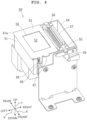
FIG. 4 is a perspective view depicting the outer appearance of amaintenance apparatus 50 according to the embodiment of the present invention. -
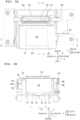
FIG. 5A is a top view of themaintenance apparatus 50, andFIG. 5B is a cross-sectional view of a main part of themaintenance apparatus 50, taken along a B-B line ofFIG. 5A . -
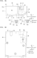
FIG. 6A is a cross-sectional view of the main part of themaintenance apparatus 50, taken along a A-A line ofFIG. 5A , andFIG. 6B is a rear side view of themaintenance apparatus 50. -
FIG. 7 is a perspective view depicting the inside of a flushingbox 51 and the inside of astorage tank 54. -
FIG. 8 is a flowchart indicating an image recording processing of thecontroller 100. - A
maintenance apparatus 50 and a printer 10 (an example of an "image recording apparatus") according to an embodiment of the present invention will be explained below. It goes without saying that the embodiment described below is merely an example of the present invention and that the embodiment of the present invention can be changed as appropriate, in a range not changing the gist and spirit of the present invention. In the following explanation, advancement or movement (progress) directed from a starting point to an end point of an arrow is expressed as an "orientation", and going forth and back on a line connecting the starting point and the end point of the arrow is expressed as a "direction". Further, an up-down direction 7 is defined based on a state in which theprinter 10 is installed usably (a state ofFIG. 1 ); a front-rear direction 8 is defined while defining a side on which adischarge port 13 is provided as a front side (front surface); and a left-right direction 9 is defined while seeing theprinter 10 from the front side (front surface). The up-down direction 7, the front-rear direction 8, and the left-right direction 9 are orthogonal to one another. - The
printer 10 depicted inFIG. 1 is an image recording apparatus which records an image on a sheet S by the ink-jet recording system. The sheet S is a long sheet (paper sheet or paper) wound in a roll shape. In order to install the sheet S in theprinter 10, a through hole is formed in the winding center of the sheet S. The recording medium (recording objective medium) may be sticker sheet, fanfold paper, cut paper, or fabric, etc. - The
printer 10 is provided with acasing 11 having a shape which is substantially a rectangular parallelepiped. Thecasing 11 has a size which is placeable on a table or desk, on the floor, or on a rack, etc. Adischarge port 13 having a slit shape and extending in the left-right direction 9 is positioned in afront wall 12 of thecasing 11. From thedischarge port 13, a sheet S on which an image is recorded by theprinter 10 is discharged. The discharged sheet S is wound up, for example, by a winding device (not depicted in the drawings) attached to theprinter 10. - As depicted in
FIG. 1 , theprinter 10 has, in the inside of the casing 11: aholder 21, atensioner 22, a conveyingroller pair 23, a dischargingroller pair 24, aplaten 25, fourtanks 26A to 26D, a carriage 41 a and ahead 42. Thehead 42 is mounted on thecarriage 41. As depicted inFIG. 2 , theprinter 10 is further provided with, in the inside of thecasing 11, twoguide rails maintenance apparatus 50. As depicted inFIG. 3 , theprinter 10 further has, within thecasing 11, acontroller 100, aholder driving motor 111, a conveyingmotor 112, acarriage driving motor 113, awiper driving motor 114 and apump driving motor 115. In addition to the above-described elements or components, theprinter 10 may be further provided with a variety of kinds of sensors, a cap, etc. - The
tanks 26A to 26D store yellow, magenta, cyan, and black inks (each of which is an example of a liquid), respectively. Each of the inks is a so-called latex ink and contains a pigment, resin fine particles, and an additive. Each of the inks has a viscosity suitable for uniformly dispersing the pigment and the resin fine particles. The pigment is the color of each of the inks. The resin fine particles are used to adhere the pigment to the sheet S. For example, the resin is a synthetic resin of which temperature exceeds the glass transition temperature by being heated by a heater (not depicted in the drawings). - Note that it is sufficient that the
printer 10 is provided with at least one tank. Further, the tank may store a liquid different from the ink. The Liquid stored in the tank includes, for example, a pre-treatment liquid (a pre-processing liquid). The pre-treatment liquid may include a cationic polymer, a polyvalent metal salt (e.g., a magnesium salt), etc. The pre-treatment liquid has a function of preventing any ink blurring (ink blotting) and/or any ink bleed-through (back-through), by causing a component in the ink to aggregate or precipitate. In some cases, the pre-treatment liquid also has a function of improving the color developing property and/or the quick-drying property of the ink. - A pair of side frames (not depicted in the drawings) extending in the up-down
direction 7 and the front-rear direction 8 are located in the inside of thecasing 11. Theholder 21 has arotation shaft 31 which supports the sheet S. Therotation shaft 31 extends in the left-right direction 9 and both ends of therotation shaft 31 are fixed to the side frames. The power from the holder driving motor 111 (seeFIG. 3 ) is transmitted to therotation shaft 31. This power causes theholder 21 to rotate in the circumferential direction of therotation shaft 31. InFIG. 1 , the direction of rotation of theholder 21 is counterclockwise. By the rotation of theholder 21, a roll body supported by theholder 21 also rotates. By the rotation of the conveyingroller pair 23 and the dischargingroller pair 24, the sheet S is drawn upwardly from a rear end of the roll body, and is guided to thetensioner 22. - The
tensioner 22, the conveyingroller pair 23 and the dischargingroller pair 24 each extend in the left-right direction 9 between the side frames, and each are attached to be rotatable in the circumferential direction of a rotational axis parallel to the left-right direction 9. A rearward urging force is applied to thetensioner 22 by an urging member such as a spring, etc. Thetensioner 22 makes contact with the sheet S drawn from the roll body and guides the sheet S to be curved forward. - The conveying
roller pair 23 has adrive roller 32 and apinch roller 33, and is positioned at a location in front of thetensioner 22. The dischargingroller pair 24 has adrive roller 34 and apinch roller 35 and is positioned at a location further in front of the conveyingroller pair 23. The positions of lower ends, respectively, of thedrive rollers tensioner 22 in the up-downdirection 7. Thepinch roller 33 makes contact with thedrive roller 32 from a position below thedrive roller 32. Thepinch roller 35 makes contact with thedrive roller 34 from a position below thedrive roller 34. - The power from the conveying motor 112 (see
FIG. 3 ) is transmitted to thedrive rollers drive rollers drive roller 32 conveys the sheet S in theconveyance orientation 6 while nipping the sheet S between thedrive roller 32 and thepinch roller 33, and thedrive roller 34 conveys the sheet S in theconveyance orientation 6 while nipping the sheet S between thedrive roller 34 and thepinch roller 35. In this embodiment, theconveyance orientation 6 is frontward (frontward orientation). - The
platen 25 is attached to the side frames at a location between the conveyingroller pair 23 and the dischargingroller pair 24 in the front-rear direction 8. Theplaten 25 extends in the left-right direction 9 between the side frames and has asupport surface 36, for the sheet S, which spreads or extends in the front-rear direction 8 and the left-right direction 9. Thesupport surface 36 is an upper end surface of theplaten 25. An up-down position (position in the up-down direction 7) of thesupport surface 36 is substantially coincident with the position of the upper end of thetensioner 22. Theplaten 25 may be a suction platen which is configured to attract the sheet S, by suction, onto thesupport surface 36. - As depicted in
FIG. 2 , the guide rails 37, 38 extend parallel to each other in the left-right direction 9. The positions in the up-downdirection 7 of the guide rails 37 and 38 are same. Theguide rail 38 is positioned behind theguide rail 37 in the front-rear direction 8. Both ends of each of the guide rails 37 and 38 are fixed to the side frames. Thecarriage 41 is supported by the guide rails 37 and 38. The power of the carriage driving motor 113 (seeFIG. 3 ) is transmitted to a carriage driving mechanism (not depicted in the drawings). Thecarriage 41 is moved in the left-right direction 9 by the action of the carriage driving mechanism in a state that thecarriage 41 is supported by the guide rails 37, 38. - As depicted in
FIG. 1 , thehead 42 is mounted on thecarriage 41. A lower surface of thehead 42 is referred to as anozzle surface 43. A plurality ofnozzles 44 which are configured to discharge the inks are formed in thenozzle surface 43. Thetanks 26A to 26D and thehead 42 are connected via an ink channel (not depicted in the drawings). The inks stored, respectively, in thetanks 26A to 26D are supplied to thehead 42 via the ink channel. While thecarriage 41 is moving in the left-right direction 9, the ink(s) supplied to thehead 42 is (are) discharged or ejected from the plurality ofnozzles 44. With this, image recording is performed on the sheet S. - As depicted in
FIG. 3 , thecontroller 100 includes aCPU 101, aROM 102, aRAM 103, anEEPROM 104 and anASIC 105. TheROM 102 stores various kinds of data, etc., necessary for the operation of thecontroller 100. TheRAM 103 is a working memory of theCPU 101. TheEEPROM 104 stores a control program, etc., executed by theCPU 101. Before theprinter 10 performs the image recording, the control program stored in theEEPROM 104 is copied to theRAM 103. TheCPU 101 executes the control program stored inRAM 103. With this, thecontroller 100 executes an image recording processing which will be described later on. - The
controller 100 is electrically connected, via theASIC 105, to theholder driving motor 111, the conveyingmotor 112, thecarriage driving motor 113, thewiper driving motor 114, thepump driving motor 115 and thehead 42. Each of theholder driving motor 111, the conveyingmotor 112, thecarriage driving motor 113, thewiper driving motor 114, thepump driving motor 115 rotates in accordance with the control from thecontroller 100, and generates the power (motive power). Thehead 42 discharges the ink(s) with respect to the sheet S which is being conveyed on theplaten 25, in accordance with the control from thecontroller 100. - The
holder 21 rotates by the power from theholder driving motor 111. Thedrive rollers motor 112. The sheet S is conveyed in theconveyance orientation 6 by the power from the conveyingmotor 112. Thecarriage 41 moves in the left-right direction 9 by the power from thecarriage driving motor 113. Awiper unit 55 included in themaintenance apparatus 50 performs an operation which will be described later on by the power from thewiper driving motor 114.Pumps maintenance apparatus 50 perform an operation which will be described later on by the power from thepump driving motor 115. Note that it is allowable that some of theholder driving motor 111, the conveyingmotor 112, thecarriage driving motor 113, thewiper driving motor 114 and thepump driving motor 115 may be realized by a common motor (one motor). Further, it is allowable that the motor driving thepump 122 and the motor driving thepump 126 may be separate motors. - As depicted in
FIG. 2 , theplaten 25 has a shape which is long in the left-right direction 9 and is located at a position which is below thecarriage 41 in the up-down direction 7 (seeFIG. 1 ). A left end of theplaten 25 is positioned, in the left-right direction 9, in the vicinity of left ends of the guide rails 37 and 38. A right end of theplaten 25 is positioned, in the left-right direction 9, at a location on the right side with respect to the centers in the left-right direction 9, respectively, of the guide rails 37, 38. Themaintenance apparatus 50 is positioned, in the left-right direction 9, on the right side with respect to theplaten 25. While theprinter 10 is executing the image recording, thecarriage 41 moves in the left-right direction 9 within a range of theplaten 25. While theprinter 10 is not executing the image recording, thecarriage 41 is located at a position which is on the right side with respect to the maintenance apparatus 50 (hereinafter referred to as a "standby position"). - As depicted in
FIG. 4 , themaintenance apparatus 50 is provided with aflushing box 51, a flushingfoam 52, a plate member (plate) 53, astorage tank 54, thewiper unit 55, and twowipers FIG. 6A , themaintenance apparatus 50 is further provided with thepump waste liquid tank 124 and a cleaningliquid tank 128. Theflushing box 51, the flushingfoam 52, theplate member 53, thepump 122 and thewaste liquid tank 124 are elements or components for the flushing processing. Thestorage tank 54, thewiper unit 55, thewipers pump 126, and the cleaningliquid tank 128 are elements for a wiping processing. - As depicted in
FIGs. 4 ,5A ,6A and7 , thestorage tank 54 is adjacent to theflushing box 51 and is positioned on the right side with respect to theflushing box 51. Theflushing box 51 and thestorage tank 54 are integrally formed (formed as a single unit).FIG. 7 depicts the inside of each of theflushing box 51 and thestorage tank 54 in a state that the flushingfoam 52, theplate member 53, thewiper unit 55 and thewipers - As depicted in
FIG. 7 , theflushing box 51 has a box-like shape which does not have an upper surface. As depicted inFIGs. 5B and6A , theflushing box 51 is configured to accommodate or store the flushingfoam 52 therein. The flushingfoam 52 is formed of a porous material. The flushingfoam 52 is, for example, a sponge. The flushingfoam 52 is an example of a "foam". Theflushing box 51 is an example of an "accommodating box". - As depicted in
FIGS. 4 and5A , theplate member 53 is configured to cover an upper part of theflashing box 51. Theplate member 53 has anopening 58 which is located in a central part of theplate member 53 and which exposes a part of the upper surface of the flashingfoam 52 in a state that theplate member 53 is locked to theflushing box 51. Theplate member 53 covers the entirety of the upper part of theflushing box 51, except for the position at which theopening 58 is located. In the state that theplate member 53 is locked to theflushing box 51, theplate member 53 apply a downward force to the flushingfoam 52 accommodated in theflushing box 51. - In a case that the
controller 100 performs the flushing processing, thecontroller 100 moves thecarriage 41 to a location above theflushing box 51. Theopening 58 is formed so that all the plurality ofnozzles 44 of thehead 42 face the flushingfoam 52 in a case thatcarriage 41 is positioned above theflushing box 51. Theplate member 53 has anopening 58 corresponding to at least all of the plurality ofnozzles 44 of thehead 42. It is desired that the shape of theopening 58 is same as the shape of an arrangement area in which the plurality ofnozzles 44 are arranged in thehead 42. It is more desired that the size of theopening 58 is same as, or is slightly greater than, the size of the arrangement area of the plurality ofnozzles 44 in thehead 42. The flushingfoam 52 accommodated in theflushing box 51 is used to absorb the ink(s) discharged from the plurality ofnozzles 44 of thehead 42 by the flushing processing. - As depicted in
FIG. 7 , theflushing box 51 has alower wall 61, afront wall 62, aleft wall 63, arear wall 64, and apartition 65. In a case that such a situation is considered thepartition 65 is extended upward so as to be a virtual right wall facing theleft wall 63, thelower wall 61, thefront wall 62, theleft wall 63, therear wall 64 and the virtual right wall partition or define the internal space of theflushing box 51. - The
front wall 62 has tworibs flushing box 51. Therear wall 64 has tworibs flushing box 51. The bottom surface of each of theribs 66a to 66d is fixed to an inner surface of the lower wall 61 (a surface, of thelower wall 61, on the side of the internal space of the flushing box 51). - A
rib 71 being annular (annular rib) protruding towards the internal space of theflushing box 51 is located at a central part of the inner surface of thelower wall 61. The planar shape of therib 71 is substantially rectangular. In a case that the flushingfoam 52 is placed in theflushing box 51 in a state that theplate member 53 does not cover the upper part of theflushing box 51, a bottom surface of the flushingfoam 52 makes contact with an upper surface of therib 71 without being deformed. Afterwards, in a case that theplate member 53 covers the upper part of theflushing box 51, a part, of the bottom surface of the flushingfoam 52 accommodated in theflushing box 51, which makes contact with the upper surface of therib 71 is deformed, and a part of therib 71 bites into the flushingfoam 52. In this state, therib 71 supports the bottom surface of the flushingfoam 52. In such a manner, an inner bottom surface of theflushing box 51 has therib 71 which supports the bottom surface of the flushingfoam 52, while deforming the part of the bottom surface of the flushingfoam 52. - A recessed
part 72 is positioned in a part, in the inner surface of thelower wall 61, which is surrounded by therib 71. The recessedpart 72 is a part which is further away outwardly from the internal space of theflushing box 51 as closer to the center of the recessedpart 72, and which is formed by four triangular-shaped inclined surfaces 73. Anexhaust port 74 is positioned at the center of the recessedpart 72. In such a manner, the inner bottom surface of theflushing box 51 has the recessedpart 72 which is recessed in an orientation of enlarging or expanding the internal space of theflushing box 51. - As depicted in
FIGs. 5B and6A , aspace 75 is defined by the bottom surface of the flushingfoam 52, the side surface at the inside of therib 71 and the part, of the inner surface of thelower wall 61 of theflushing box 51, which is surrounded by the rib 71 (including the four inclined walls 73). In a case that the flushingfoam 52 is considered as one solid body, thespace 75 is an enclosed (sealed) space. - As depicted in
FIG. 6A , thespace 75 is connected to one end of thepump 122 via theexhaust port 74 and atube 121. The other end of thepump 122 is connected to one end of thetube 123, and thewaste liquid tank 124 is positioned at the other end of thetube 123. In a case that thepump 122 is driven by the pump driving motor 115 (seeFIG. 3 ), thepump 122 imparts a negative pressure to thespace 75. - The plate member (plate-like member, plate) 53 is a member obtained by forming the
openings 58 in a plate made of a metal (hereinafter referred to as a "metal plate") and by machining the respective ends of the metal plate. As depicted inFIG. 6A , avertical part 81a is formed at a left end of theplate member 53 and avertical part 81b is formed at a right end of theplate member 53. Thevertical part 81a is formed by bending an end (a part which becomes to be a left end), of the metal plate, so that the end is orthogonal to an upper surface of theplate member 53. Thevertical part 81b is formed by bending a facing end (a part which becomes to be a right end) which faces the end, of the metal plate, so that the facing end is orthogonal to the upper surface of theplate member 53. Thevertical parts plate member 53 is locked to theflushing box 51, thevertical parts plate member 53 from deviating in the left-right direction 9. - As depicted in
FIG. 5B , avertical part 82 and ahorizontal part 83 are formed in a rear end of theplate member 53. Thevertical part 82 is formed by bending another end of the metal sheet (a part which becomes the rear end of the plate member 53) so that the another end is orthogonal to the upper surface of theplate member 53. Thehorizontal part 83 is formed by bending the bent part of the metal sheet further outwardly (in a direction separated from the center of the plate 53) so that the further bent part is parallel to the upper surface of theplate 53. - As depicted in
FIG. 6B , therear wall 64 of theflushing box 51 is fixed to acasing 84 of themaintenance apparatus 50. As depicted inFIG. 7 , therear wall 64 of theflushing box 51 has anopening 85 which is configured to allow aforward end part 83a of thehorizontal part 83 of theplate member 53 to pass therethrough. Theforward end part 83a of thehorizontal part 83 is inserted into theopening 85. Theforward end part 83a of thehorizontal part 83 has an opening (not depicted in the drawings) configured to allow an upper part of aplate spring 86 to pass therethrough. The upper part of theplate spring 86 is inserted into the opening of theforward end part 83a of thehorizontal part 83. As depicted inFIG. 6B , a lower part of theplate spring 86 is fixed to thecasing 84 of themaintenance apparatus 50. The upper part of theplate spring 86 urges theforward end part 83a in an orientation away from therear wall 64 of theflushing box 51. In such a manner, the rear end of theplate member 53 is fixed to theflushing box 51 via theplate spring 86. Theplate spring 86 urges theplate member 53 in an orientation away from the upper part of theflushing box 51. The rear end of theplate member 53 is an example of a "first end" of theplate member 53. - As depicted in
FIGs. 5A and 5B , an operatingpart 87 and ahook 88 are formed in a front end of theplate member 53. The operatingpart 87 is a part of which width is narrower than that of the front end of theplate member 53. The operatingpart 87 has a width suitable for a user of theprinter 10 to lift the operatingpart 87 upwardly with a finger of the user. Thehook 88 is formed by bending a metal plate of which width is narrower than that of the metal plate forming theplate member 53 in a direction of 90° and in a direction of 60°. Thehook 88 is fixed to the front end of theplate member 53. - As depicted in
FIG. 7 , ahook receiving part 89 is located at the outside of thefront wall 62 of theflushing box 51. The position of thehook receiving part 89 is a position which is close to thehook 88 in a case that theplate member 53 covers the upper part of theflushing box 51. In a case that theplate member 53 covers the upper part of theflushing box 51, thehook 88 engages with thehook receiving part 89 and theplate member 53 is locked to theflushing box 51. In such a manner, the front end of theplate member 53 is locked to theflushing box 51 via the hook structure. The front end of theplate member 53 is an example of a "second end", of theplate member 53, which faces the rear end of theplate member 53. - In a case that the flushing processing is performed repeatedly, there arises a need to exchange the flushing
foam 52. In a case that the user of theprinter 10 exchanges the flushingfoam 52, the user lifts theoperating part 87 upwardly until thehook 88 is detached from thehook receiving part 89. In a case that thehook 88 is detached from thehook receiving part 89, theplate member 53 rotates with the rear end side thereof as the center of rotation due to the urging force of theplate spring 86, and is away from the upper part of theflushing box 51. In this situation, theplate member 53 is away from the upper part of theflushing box 51 so that an angle defined between theplate member 53 and the upper part (or a plane within which the upper end of theflushing box 51 extends) of the flushingmember 53 is within a range of approximately 10° to approximately 45°. - As depicted in
FIG. 7 thestorage tank 54 has a box-like shape which does not have an upper part. As depicted inFIG. 6A , thestorage tank 54 stores a cleaning liquid L in the inside thereof. The cleaning liquid L is a liquid suitable for removing any unwanted substance (unnecessary matter) adhered to thenozzle surface 43 of thehead 42. As the cleaning liquid L, for example, glycerin is used. - The
wipers wiper unit 55 so that forward end parts, respectively, of thewipers storage tank 54. Thewiper 56 is not impregnated with the cleaning liquid L and deforms in response to an external force while maintaining the shape of thewiper 56 to some extent. On the other hand, thewiper 57 is impregnated with the cleaning liquid L and deforms, with a high degree of freedom, in response to the external force. Thewiper 56 is formed, for example, of a rubber material. Thewiper 57 is formed, for example, of a porous material. - As depicted in
FIG. 4 , thewiper unit 55 has arotation shaft 59. As depicted inFIG. 7 , thefront wall 91 of thestorage tank 54 has asupport part 93 and therear wall 92 of thestorage tank 54 has asupport part 94. Thesupport part 93 is configured to support one end of therotation shaft 59 of thewiper unit 55, and thesupport part 94 is configured to support the other end of therotation shaft 59. With this, thewiper unit 55 is supported by thestorage tank 54 so that thewiper unit 55 is rotatable with therotation shaft 59 as the center of the rotation. - The power of the wiper driving motor 114 (see
FIG. 3 ) is transmitted to a wiper driving mechanism (not depicted in the drawings), thereby causing therotation shaft 59 of thewiper unit 55 to make a half rotation; accompanying with this, thewiper unit 55 and thewipers rotation shaft 59 as the center of the half rotation. With this, thewiper unit 55 is moved between a position at which the forward end parts of thewipers FIG. 6A ; hereinafter referred to as an "upward position") and a position at which the forward end parts of thewipers - In a case that the
wiper unit 55 is located at the upward position, thewipers storage tank 54, and are located at a position at which thewipers nozzle surface 43 of thehead 42. In a case that thewiper unit 55 is located at the downward position, a part of thewiper 56 and a part of thewiper 57 are immersed in the cleaning liquid L stored in thestorage tank 54, and thewipers wipers nozzle surface 43. - As depicted in
FIGs. 6A and7 , a lower wall of thestorage tank 54 is constructed of twoinclined walls inclined wall 95 extends in the front-rear direction 8 and is positioned on the right side with respect to theflushing box 51. Theinclined wall 96 extends in the front-rear direction 8 and is positioned further on the right side with respect to theinclined wall 95. A right end of theinclined wall 95 and a left end of theinclined wall 96 are at a same height and are connected to each other so that the cleaning liquid L does not leak. A left end of theinclined wall 95 is located at a position slightly higher than a position of the right end of theinclined wall 95. A right end of theinclined wall 96 is located at a position higher than a position of the left end of theinclined wall 96. Asupply port 97 of the cleaning liquid L is located at a position, in a connection part at which theinclined walls rear wall 92. - As depicted in
FIG. 6A , thesupply port 97 is connected to one end of thepump 126 via atube 125. The other end of thepump 126 is connected to the cleaningliquid tank 128 via atube 127. The cleaningliquid tank 128 stores an unused cleaning liquid. In a case that thepump 126 is driven by the pump driving motor 115 (seeFIG. 3 ), thepump 126 supplies the unused cleaning liquid stored in the cleaningliquid tank 128 to thestorage tank 54. The cleaning liquid L stored in thestorage tank 54 is supplied from the cleaningliquid tank 128 to thestorage tank 54 by using thepump 126. Thestorage tank 54 and thepump 126 are an example of a supplying part (liquid supplier) configured to supply the cleaning liquid to theflushing box 51. - As depicted in
FIGs. 6A and7 , theflushing box 51 and thestorage tank 54 are partitioned from each other by thepartition 65. Thepartition 65 is lower than thefront wall 62, theleft wall 63 and therear wall 64. In a case that thepump 126 is operated and that the cleaning liquid is supplied from the cleaningliquid tank 128 to thestorage tank 54, a part of the cleaning liquid L stored in thestorage tank 54 flows over thepartition 65 and flows into the inside of theflushing box 51. The cleaning liquid L flowed into the inside of theflushing box 51 flows through the space at the outside of therib 71 and surrounds the outer side of therib 71. The cleaning fluid L located at the outside of therib 71 is absorbed by the flushingfoam 52 and diffuses in the inside of the flushingfoam 52. - With reference to
FIG. 8 , an image recording processing by thecontroller 100 will be explained. At a point of time that thecontroller 100 reaches step S11, thecarriage 41 is located at the standby position and thewiper unit 55 is located at the downward position. At this time, the part of thewiper 56 and the part of thewiper 57 are immersed in the cleaning liquid L stored in thestorage tank 54. - The
controller 100 receives an image recording instruction from an operation part (not depicted in the drawings) (step S11). Specifically, thecontroller 100 stands by in step S11 until thecontroller 100 receives the image recording instruction. In a case that thecontroller 100 receives the image recording instruction in step S11, thecontroller 100 controls thewiper driving motor 114 to thereby move thewiper unit 55 to the upward position (step S12). - Next, the
controller 100 executes a wiping processing (step S13). In step S13, thecontroller 100 controls thecarriage driving motor 113 to thereby cause thecarriage 41 to move in the leftward orientation from the standby position to a position above thewiper unit 55. In this situation, thecarriage 41 moves in the leftward orientation while thewipers nozzle surface 43 of thehead 42. Thecontroller 100 controls thecarriage driving motor 113 to thereby cause thecarriage 41 to move to a position at which thewipers nozzle surface 43 of thehead 42. At this point of time, thecontroller 100 ends the wiping processing. Next, thecontroller 100 controls thewiper driving motor 114 to thereby cause thewiper unit 55 to move to the downward position (step S14). - Next, the
controller 100 controls thecarriage driving motor 113 to thereby move thecarriage 41 in the leftward orientation to a recording start position (step S15). The recording start position is a predetermined position at which thecarriage 41 faces theplaten 25. Next, thecontroller 100 controls theholder driving motor 111 and the conveyingmotor 112 to thereby convey the sheet S to the recording start position (step S16). Note that it is allowable that thecontroller 100 executes step S16 in parallel to all or a part of steps S12 to S15. - Next, the
controller 100 executes image recording on the sheet S (step S17). In step S17, thecontroller 100 controls thecarriage driving motor 113 to thereby move thecarriage 41 in the left-right direction 9 (to move leftward or rightward orientation). Thecontroller 100 controls thehead 42 while thecarriage 41 is moving in the left-right direction 9, thecontroller 100 thereby causes the plurality ofnozzles 44 of thehead 42 to discharge the ink(s) in an amount corresponding to image data. - Next, the
controller 100 determines whether there is any remaining image data (step S18). In accordance with the determination made by thecontroller 100 that there is the remaining image data in step S18 (step S18: YES), thecontroller 100 proceeds to step S19. In this case, thecontroller 100 controls the conveyingmotor 112 to thereby convey the sheet S by a predetermined amount (step S19). Then, thecontroller 100 proceeds to step S17. - In accordance with the determination made by the
controller 100 that there is not any remaining image data in step S18 (step S18: NO), thecontroller 100 proceeds to step S20. In this case, thecontroller 100 controls the conveyingmotor 112 to thereby discharge the sheet S up to a predetermined position (step S20). Next, thecontroller 100 controls thecarriage driving motor 113 to thereby move thecarriage 41 in the rightward orientation up to the standby position (step S21). Then, thecontroller 100 proceeds to step S11 so as to execute a next image recording. - In a case, for example, that an elapsed time which has elapsed since the flushing processing executed the last time exceeds a threshold value or in a case that the
controller 100 receives an instruction from the user of theprinter 10, thecontroller 100 determines that the flushing processing needs to be performed. Thecontroller 100 performs the flushing processing in accordance with the determination made by thecontroller 100 that the flushing processing needs to be performed. - As described above, in a case that the
controller 100 performs the flushing processing, thecontroller 100 controls thecarriage driving motor 113 to thereby cause thecarriage 41 to move to the location above flushingbox 51. Theopening 58 is formed such that, in a case that thecarriage 41 is positioned above theflushing box 51, all of the plurality ofnozzles 44 of thehead 42 face the flushingfoam 52. Thecontroller 100 performs a control of causing thehead 42 to discharge the ink(s) in an amount, which is suitable for the flushing processing, from the plurality ofnozzles 44. The flushingfoam 52 accommodated in theflushing box 51 absorbs the ink(s) discharged from the plurality ofnozzles 44 of thehead 42 by the flushing processing. - Since the flushing
foam 52 is impregnated with the cleaning liquid L, the ink(s) absorbed by the flushingfoam 52 moves downwardly, together with the cleaning liquid L, in the inside of the flushingfoam 52, and reaches thespace 75 defined at the location below the bottom surface of the flushingfoam 52. - The
controller 100 drives the pump driving motor 115 (seeFIG. 3 ) while performing the flushing processing or after performing the flushing processing to thereby operate or drive thepump 122. Thepump 122 applies a negative pressure to thespace 75. Accordingly, the ink and the cleaning liquid L in the inside of the flushingfoam 52 are sucked and move quickly downward, and the ink and the cleaning liquid L which have reached thespace 75 are sucked and moved to thewaste liquid tank 124. - As described above, the
maintenance apparatus 50 according to the present embodiment includes: the flushingfoam 52 configured to absorb the ink(s) discharged from the plurality ofnozzles 44 of thehead 42; theflushing box 51 which does not have any upper surface and which is configured to accommodate the flushingfoam 52, and theplate member 53 configured to cover the upper part of the flushingfoam 52. Theplate member 53 has theopening 58 configured to expose the part of the upper surface of the flushingfoam 52 in the state that theplate member 53 is locked to theflushing box 51. - According to the
maintenance apparatus 50 according to the present embodiment, theplate member 53 having theopening 58 is used so as to cover the upper part of theflushing box 51, thereby making it possible to press the flushingfoam 52 downwardly while exposing the part of the upper surface of the flushingfoam 52. Accordingly, it is possible to maintain the distance between the flushingfoam 52 and thehead 42 appropriately, and to effectively prevent any contact between the flushingfoam 52 and thenozzle surface 43 of thehead 42. Also according to theprinter 10 according the present embodiment, the similar effect can be obtained. - The
printer 10 performs the image recording by using the latex ink. Accordingly, regarding theprinter 10, any inconvenience that the ink adhered to the member covering the flushing box makes contact with the nozzle surface of the head is more likely to occur, as compared with a printer using a general ink. Even in such a case, it is possible to press the flushingfoam 52 downwardly by theplate member 53, to maintain the distance between the flushingfoam 52 and thehead 42 appropriately, and to prevent any contact between the flushingfoam 52 and thenozzle surface 43 of thehead 42. The present invention is effective particularly regarding a case wherein the image recording is performed by using the latex ink(s). - Further, the
plate member 53 has the opening corresponding at least all the plurality ofnozzles 44 of thehead 42. Accordingly, it is possible to absorb the inks discharged from all the plurality ofnozzles 44 with the flushingfoam 52, without allowing the inks to adhere to theplate member 53. Furthermore, the inner bottom surface of theflushing box 51 has therib 71 which supports the bottom surface of the flushingfoam 52 while deforming the part of the bottom surface of the flushingfoam 52. Accordingly, it is possible to suppress any bulging or lifting of the upper surface of the flushingfoam 52 which is pressed by theplate member 53. - Moreover, the inner bottom surface of the
flushing box 51 has the recessedpart 72 which is recessed in the orientation of enlarging the internal space of theflushing box 51. Accordingly, it is possible to collect the ink absorbed by the flushingfoam 52 to the recessedpart 72 of theflushing box 51. Further, in a case that the height of therib 71 is not sufficient, it is possible to release the flushingfoam 52 to the recessedpart 72, and to flatten the upper surface of the flushingfoam 52. - Furthermore, the rear end of the
plate member 53 is fixed to theflushing box 51 via theplate spring 86, the front end of theplate member 53 is locked to theflushing box 51 via the hook structure having thehook 88 and thehook receiving part 89, and theplate spring 86 urges theplate member 53 in the orientation away from the upper part of theflushing box 51. Accordingly, by hooking (engaging) thehook 88 with respect to thehook receiving part 89, it is possible to lock theplate member 53 to theflushing box 51. In a case that thehook 88 is disengaged (is away) from thehook receiving part 89, the action of theplate spring 86 causes theplate member 53 to rotate with the rear end side of theplate member 53 as the center of rotation, and is detached from the upper part of theflushing box 51. Accordingly, it is possible to prevent such a situation that the user of theprinter 10 fails to lock theplate member 53 to theflushing box 51 at a time of exchanging the flushingfoam 52. - Moreover, the
maintenance apparatus 50 has the supplying part configured to supply the cleaning liquid to theflushing box 51. Accordingly, the cleaning liquid supplied from the supplying part is stored in theflushing box 51, and the flushingfoam 52 accommodated in theflushing box 51 is impregnated with the cleaning liquid. Accordingly, by the action of the cleaning liquid with which the flushingfoam 52 is impregnated, it is possible to suppress the occurrence of such a situation that the ink discharged from the plurality ofnozzles 44 of thehead 42 remains in the inside of the flushingfoam 52. - Further, the
plate member 53 covers the entirety of the upper part of theflushing box 51, except for the position at which theopening 58 is provided; the size of theopening 58 is substantially same as the size of the arrangement area of the plurality ofnozzles 44 in thehead 42. Accordingly, it is possible to suppress evaporation of the cleaning liquid stored in theflushing box 51, while absorbing, with the flushingfoam 52, the ink(s) discharged from the plurality ofnozzles 44 of thehead 42 by the flushing processing, without allowing the ink(s) discharged from the plurality ofnozzles 44 to adhere to theplate member 53. - Various modifications can be configured for the
maintenance apparatus 50 according to the present embodiment. In themaintenance apparatus 50, theplate member 53 is configured to have theopening 58 corresponding at least to all the plurality ofnozzles 44 of thehead 42. Regarding the maintenance apparatus according to a modification, it is allowable that thehead 42 has, in thenozzle surface 43, not less than one piece of a nozzle row in which a plurality ofnozzles 44 are aligned in the front-rear direction 8 or the left-right direction 9, and that theplate member 53 has an opening corresponding to the at least one piece of the nozzle row of thehead 42. In such a case, thecontroller 100 performs the flushing processing while moving thecarriage 41. According to the maintenance apparatus according to the modification, it is possible to absorb, with the flushingfoam 52, the ink(s) discharged from the plurality ofnozzles 44 within the nozzle row of thehead 42, without allowing the ink(s) discharged from the plurality ofnozzles 44 to adhere to theplate member 53. - In the
maintenance apparatus 50, therib 71 is configured to be the annular rib. Regarding the maintenance apparatus according to a modification, it is not necessarily indispensable that therib 71 is an annular rib. In themaintenance apparatus 50, the inner bottom surface of theflushing box 51 is configured to have the recessedpart 72. Regarding the maintenance apparatus according to a modification, it is not necessarily indispensable that the inner bottom surface of theflushing box 51 is configured to have the recessedpart 72. - In the
maintenance apparatus 50, the rear end of theplate member 53 is configured to be fixed to theflushing box 51 via theplate spring 86, and the front end of theplate member 53 is configured to be locked to theflushing box 51 via the hook structure. Regarding the maintenance apparatus according to a modification, theplate member 53 may be locked to theflushing box 51 by a method which is different from that described above. For example, the front end and the rear end of theplate member 53 may be locked to theflushing box 51 via a hook structure. Alternatively, the four ends of theplate member 53 may all be locked to theflushing box 51. Still alternatively, not less than one end of theplate member 53 may be locked to theflushing box 51 by a means different from the hook structure. - In the
maintenance apparatus 50, theflushing box 51 and thestorage tank 54 are integrally formed. In the maintenance apparatus according to a modification, theflushing box 51 and thestorage tank 54 may be formed separately. It is allowable that the maintenance apparatus according to a modification does not have the elements for the wiping processing (thestorage tank 54, thewiper unit 55, and thewipers 56, 57). In this case, it is allowable that the maintenance apparatus according to the modification has a supplying part configured to supply the cleaning liquid to theflushing box 51, not via thestorage tank 54. -
- 10:
- printer (image recording apparatus)
- 42:
- head
- 44:
- nozzle
- 50:
- maintenance apparatus
- 51:
- flushing box (accommodating box)
- 52:
- flushing foam (foam)
- 53:
- plate member
- 54:
- storing tank (a part of a supplying part (a liquid supplier))
- 58:
- opening
- 71:
- rib
- 72:
- recessed part
- 86:
- plate spring
- 88:
- hook (a part of a hook structure)
- 89:
- hook receiving part (a part of the hook structure)
- 126:
- pump (a part of the supplying part (the liquid supplier))
Claims (10)
- A maintenance apparatus for an image recording apparatus provided with a head having a nozzle configured to discharge a liquid, the maintenance apparatus comprising:a foam configured to absorb the liquid discharged from the nozzle;an accommodating box which does not have an upper surface and which is configured to accommodate the foam; anda plate configured to cover an upper part of the accommodating box,wherein the plate has an opening configured to expose a part of an upper surface of the foam in a state that the plate is locked to the accommodating box.
- The maintenance apparatus according to claim 1, wherein the opening of the plate corresponds at least to one nozzle row of the head.
- The maintenance apparatus according to claim 1 or 2, wherein the opening of the plate corresponds at least to all of the nozzle of the head.
- The maintenance apparatus according to any one of claims 1 to 3, wherein an inner bottom surface of the accommodating box has a rib configured to support a bottom surface of the foam.
- The maintenance apparatus according to any one of claims 1 to 4, wherein an inner bottom surface of the accommodating box has a recess which is recessed in an orientation of enlarging an internal space of the accommodating box.
- The maintenance apparatus according to any one of claims 1 to 5, wherein a first end of the plate is fixed to the accommodating box via a plate spring;a second end, of the plate, facing the first end is locked to the accommodating box via a hook structure; andthe plate spring is configured to urge the plate in an orientation away from the upper part of the accommodating box.
- The maintenance apparatus according to any one of claims 1 to 6, further comprising a liquid supplier configured to supply a cleaning liquid to the accommodating box.
- The maintenance apparatus according to any one of claims 1 to 7, wherein the plate is configured to apply a downward force to the foam in the state that the plate is locked to the accommodating box.
- The maintenance apparatus according to any one of claims 1 to 8, wherein the plate is made of a metal.
- An image recording apparatus comprising:a head having a nozzle configured to discharge a liquid;a carriage configured to move in a state that the head is mounted on the carriage; andthe maintenance apparatus as defined in any one of claims 1 to 9.
Applications Claiming Priority (1)
| Application Number | Priority Date | Filing Date | Title |
|---|---|---|---|
| JP2022039826A JP7639743B2 (en) | 2022-03-15 | 2022-03-15 | Maintenance device and image recording device |
Publications (1)
| Publication Number | Publication Date |
|---|---|
| EP4245545A1 true EP4245545A1 (en) | 2023-09-20 |
Family
ID=85571352
Family Applications (1)
| Application Number | Title | Priority Date | Filing Date |
|---|---|---|---|
| EP23161283.9A Pending EP4245545A1 (en) | 2022-03-15 | 2023-03-10 | Maintenance apparatus and image recording apparatus |
Country Status (3)
| Country | Link |
|---|---|
| US (1) | US12370797B2 (en) |
| EP (1) | EP4245545A1 (en) |
| JP (1) | JP7639743B2 (en) |
Citations (9)
| Publication number | Priority date | Publication date | Assignee | Title |
|---|---|---|---|---|
| JPH08276598A (en) * | 1995-04-07 | 1996-10-22 | Canon Inc | Liquid ejecting apparatus and information processing system |
| US7195334B2 (en) * | 2002-08-26 | 2007-03-27 | Seiko Epson Corporation | Head cap; liquid droplet ejection apparatus provided with head cap; method of manufacturing LCD device, organic EL device; electron emission device, PDP device, electrophoretic display device, color filter, and organic EL; method of forming spacer, metallic wiring, lens, resist, and light diffusion body |
| JP2007253609A (en) * | 2006-02-22 | 2007-10-04 | Ricoh Co Ltd | Head cap member, head maintenance / recovery device, droplet discharge device, image forming apparatus |
| JP2007320173A (en) * | 2006-06-01 | 2007-12-13 | Seiko Epson Corp | Cap member and liquid ejecting apparatus |
| JP2008094040A (en) * | 2006-10-16 | 2008-04-24 | Brother Ind Ltd | Cap device for liquid discharge head and liquid discharge device |
| JP2008168525A (en) | 2007-01-12 | 2008-07-24 | Seiko Epson Corp | Liquid ejector |
| US20090027444A1 (en) * | 2007-07-24 | 2009-01-29 | Seiko Epson Corporation | Liquid absorbing material, cap device and liquid ejecting apparatus |
| JP2017144727A (en) * | 2016-02-16 | 2017-08-24 | ブラザー工業株式会社 | Printer |
| EP3960470A2 (en) * | 2020-08-07 | 2022-03-02 | Seiko Epson Corporation | Capping device and liquid ejecting apparatus |
Family Cites Families (6)
| Publication number | Priority date | Publication date | Assignee | Title |
|---|---|---|---|---|
| JP2011101956A (en) | 2009-11-10 | 2011-05-26 | Seiko Epson Corp | Liquid ejector |
| US9211716B2 (en) * | 2011-09-13 | 2015-12-15 | Videojet Technologies Inc. | Capping device |
| JP2017189889A (en) * | 2016-04-12 | 2017-10-19 | セイコーエプソン株式会社 | Inkjet head maintenance method |
| JP6950199B2 (en) * | 2017-02-28 | 2021-10-13 | ブラザー工業株式会社 | Liquid discharge device |
| CN109421377B (en) * | 2017-08-24 | 2022-04-01 | 精工爱普生株式会社 | Cap device and liquid ejecting apparatus |
| WO2023112163A1 (en) | 2021-12-14 | 2023-06-22 | ローランドディー.ジー.株式会社 | Printer device |
-
2022
- 2022-03-15 JP JP2022039826A patent/JP7639743B2/en active Active
-
2023
- 2023-03-10 EP EP23161283.9A patent/EP4245545A1/en active Pending
- 2023-03-13 US US18/182,905 patent/US12370797B2/en active Active
Patent Citations (9)
| Publication number | Priority date | Publication date | Assignee | Title |
|---|---|---|---|---|
| JPH08276598A (en) * | 1995-04-07 | 1996-10-22 | Canon Inc | Liquid ejecting apparatus and information processing system |
| US7195334B2 (en) * | 2002-08-26 | 2007-03-27 | Seiko Epson Corporation | Head cap; liquid droplet ejection apparatus provided with head cap; method of manufacturing LCD device, organic EL device; electron emission device, PDP device, electrophoretic display device, color filter, and organic EL; method of forming spacer, metallic wiring, lens, resist, and light diffusion body |
| JP2007253609A (en) * | 2006-02-22 | 2007-10-04 | Ricoh Co Ltd | Head cap member, head maintenance / recovery device, droplet discharge device, image forming apparatus |
| JP2007320173A (en) * | 2006-06-01 | 2007-12-13 | Seiko Epson Corp | Cap member and liquid ejecting apparatus |
| JP2008094040A (en) * | 2006-10-16 | 2008-04-24 | Brother Ind Ltd | Cap device for liquid discharge head and liquid discharge device |
| JP2008168525A (en) | 2007-01-12 | 2008-07-24 | Seiko Epson Corp | Liquid ejector |
| US20090027444A1 (en) * | 2007-07-24 | 2009-01-29 | Seiko Epson Corporation | Liquid absorbing material, cap device and liquid ejecting apparatus |
| JP2017144727A (en) * | 2016-02-16 | 2017-08-24 | ブラザー工業株式会社 | Printer |
| EP3960470A2 (en) * | 2020-08-07 | 2022-03-02 | Seiko Epson Corporation | Capping device and liquid ejecting apparatus |
Also Published As
| Publication number | Publication date |
|---|---|
| JP2023134902A (en) | 2023-09-28 |
| US12370797B2 (en) | 2025-07-29 |
| US20230294407A1 (en) | 2023-09-21 |
| JP7639743B2 (en) | 2025-03-05 |
Similar Documents
| Publication | Publication Date | Title |
|---|---|---|
| JP7256446B2 (en) | liquid injector | |
| JP2023091088A (en) | liquid injector | |
| US10457053B2 (en) | Ink jet printer | |
| JP7139885B2 (en) | LIQUID EJECTING DEVICE, MAINTENANCE METHOD OF LIQUID EJECTING DEVICE | |
| JP2007050592A (en) | Liquid discharge head cleaning device | |
| US9221263B2 (en) | Inkjet recording device and nozzle surface wiping method for an inkjet recording device | |
| US12415360B2 (en) | Controller, control method, and image recording device | |
| US12365182B2 (en) | Image recording apparatus and method of controlling the same | |
| US12370797B2 (en) | Maintenance apparatus and image recording apparatus | |
| US12370799B2 (en) | Maintenance apparatus and image recording apparatus | |
| US9937724B2 (en) | Liquid ejecting apparatus | |
| US10926562B2 (en) | Joint mechanism and liquid ejection device including the same | |
| US12528294B2 (en) | Liquid ejection device | |
| JP7674895B2 (en) | Printer | |
| US12403697B2 (en) | Liquid discharging apparatus | |
| JP7323029B2 (en) | LIQUID EJECTING DEVICE, MAINTENANCE METHOD OF LIQUID EJECTING DEVICE | |
| JP7844172B2 (en) | liquid discharge device | |
| JP7135889B2 (en) | Liquid ejector | |
| JP7344930B2 (en) | Cap and inkjet printer with it | |
| US20220126585A1 (en) | Printing device | |
| JP2025067677A (en) | Recording device | |
| JP2024146459A (en) | Image Recording Device | |
| JP2024146458A (en) | Image Recording Device | |
| CN113195234A (en) | Waste liquid recovery device and ink jet recording apparatus provided with same | |
| JP2023066511A (en) | Liquid supply device and image recording device |
Legal Events
| Date | Code | Title | Description |
|---|---|---|---|
| PUAI | Public reference made under article 153(3) epc to a published international application that has entered the european phase |
Free format text: ORIGINAL CODE: 0009012 |
|
| STAA | Information on the status of an ep patent application or granted ep patent |
Free format text: STATUS: THE APPLICATION HAS BEEN PUBLISHED |
|
| AK | Designated contracting states |
Kind code of ref document: A1 Designated state(s): AL AT BE BG CH CY CZ DE DK EE ES FI FR GB GR HR HU IE IS IT LI LT LU LV MC ME MK MT NL NO PL PT RO RS SE SI SK SM TR |
|
| P01 | Opt-out of the competence of the unified patent court (upc) registered |
Effective date: 20230926 |
|
| STAA | Information on the status of an ep patent application or granted ep patent |
Free format text: STATUS: REQUEST FOR EXAMINATION WAS MADE |
|
| 17P | Request for examination filed |
Effective date: 20240305 |
|
| RBV | Designated contracting states (corrected) |
Designated state(s): AL AT BE BG CH CY CZ DE DK EE ES FI FR GB GR HR HU IE IS IT LI LT LU LV MC ME MK MT NL NO PL PT RO RS SE SI SK SM TR |
|
| STAA | Information on the status of an ep patent application or granted ep patent |
Free format text: STATUS: EXAMINATION IS IN PROGRESS |
|
| 17Q | First examination report despatched |
Effective date: 20250821 |